AE ¨ U Int. J. Electron. Commun. (2006) No. 7 c Gustav Fischer Verlag Jena 1 Computationally-Efficient Methods for Blind Decision Feedback Equalization of QAM Signals Kevin Banovi´ c, Esam Abdel-Raheem, and Mohammed A.S. Khalid Abstract This paper investigates computationally-efficient methods for blind decision feedback equalization (DFE) that reduce the complexity and power requirements of blind equal- ization algorithms while maintaining their steady-state charac- teristics for quadrature amplitude modulation (QAM) signals. These includethe power-of-two error (POT), selective coefficient update (SCU), and frequency-domain block (FDB) methods. A novel radius-directed stop-and-go (RSG) method is introduced, which selectively adjusts the equalizer tap coefficients based on the equalizer output radius. In addition, a new activation/de- activation method based on the equalizer output radius is uti- lized to control the feedback equalizer (FBE) of the DFEs. Sim- ulation studies and analysis are provided for empirically derived cable and microwave channels and Ricean fading channels. Keywords Adaptive filtering, decision feedback equalizers, blind equalization algorithms, fading channels 1. Introduction Adaptive equalizers compensate for signal distortion caused by intersymbol interference (ISI), whereby sym- bols transmitted before and after a given symbol cor- rupt the detection of that symbol. All physical channels tend to exhibit ISI at high enough symbol rates [1], [2]. Blind equalization schemes improve the bandwidth effi- ciency of a communication system by achieving equal- izer tap adaptation without the transmission of a training sequence [2]-[4]. Instead, blind equalization algorithms utilize known symbols statistics for equalizer tap adapta- tion until switching to the decision-directed mode after the symbol error rate (SER) has been sufficiently reduced. Recently, quadrature amplitude modulation (QAM) based communication standards were adopted for satellite, cable, and very high speed digital subscriber line (VDSL) applications. Blind equalization is recommended for both the Pan-European satellite-based Digital Video Broad- cast (DVB-S) [5] and cable-based (DVB-C) [6] standards. Broadband standards for VDSL include provisions for both single- and multiple-carrier modulation [7]. The lat- ter uses carrierless amplitude-phase (CAP) or QAM and requires the receiver to startup blindly. Although the Ad- vance Television Systems Committee (ATSC) adopted 8- vestigal side-band modulation (VSB) over 32-QAM for terrestrial high definition television (HDTV) broadcast Received July 2006. K. Banovi´ c is with the Department of Electrical and Com- puter Engineering, University of Toronto, 10 King’s College Road, Toronto, ON M5S 3G4, Canada, E. Abdel-Raheem and M.A.S. Khalid are with the Department of Electrical and Com- puter Engineering, 401 Sunset Ave., Windsor, Ontario, N9B 3P4, Canada. Email: [email protected], [email protected], [email protected]Fig. 1. Multirate system model for a decision feedback equalizer. [8], blind decision feedback equalization (DFE) was cho- sen over trained equalization. In field tests conducted by HDTV manufacturers, the blind DFE achieved a lower er- ror rate and faster data acquisition than its trained counter- part in time-varying terrestrial channels [9]. In mobile communication channels, such as those for microwave radio, high order filters are needed to achieve channel equalization. Equalizer tap adaptation is costly in terms of power, memory, and computations and can be impractical for mobile units. In this paper, we investigate computationally-efficient methods for blind DFEs, which reduce the complexity and power requirements of blind equalization algorithms while maintaining their steady- state characteristics for QAM signals. These include the power-of-two error [10], [11], selective coefficient update (also partial update) [12]-[14], and frequency-domain block methods [15]-[18]. A novel radius-directed stop- and-go method is introduced, which selectively updates the equalizer tap coefficients based on the equalizer output radius. This concept was conceived by Banovi´ c et. al. in [19] for linear equalizers, where it was termed the se- lective update method. In this reformulation for DFEs, criteria is given for selection of the static bound pa- rameter, analysis is provided for adjustment probability and transient/steady-state performance, and a modified method is proposed to reduce hardware complexity. In ad- dition, a new activation/de-activation method based on the equalizer output radius is utilized to control the feedback equalizer (FBE) of the DFEs. Simulation studies for blind DFEs employing the discussed methods are performed over empirically derived cable and microwave channels and for Ricean fading channels. 2. Fractionally-Spaced System Model In this section, a signal model is constructed for the T/2- spaced single-input single-output (SISO) baseband com- munication system for a DFE, where T is the symbol pe- riod and 1/T is the baud rate. A multirate model of the system is illustrated in Fig. 1, where the index ‘n’ de- notes T -spaced quantities while ‘k’ denotes T/2-spaced quantities. A T -spaced source symbol s(n) is transmitted through a pulse-shaping filter and modulated onto a T/2- spaced propagation channel, whose impulse response is
Computationally-Efficient Methods forBlind Decision Feedback Equalization of QAM Signals
Kevin Banovic, Esam Abdel-Raheem, and Mohammed A.S. Khalid
Abstract This paper investigates computationally-efficientmethods for blind decision feedback equalization (DFE) thatreduce the complexity and power requirements of blind equal-ization algorithms while maintaining their steady-state charac-teristics for quadrature amplitude modulation (QAM) signals.These include the power-of-two error (POT), selective coefficientupdate (SCU), and frequency-domain block (FDB) methods. Anovel radius-directed stop-and-go (RSG) method is introduced,which selectively adjusts the equalizer tap coefficients based onthe equalizer output radius. In addition, a new activation/de-activation method based on the equalizer output radius is uti-lized to control the feedback equalizer (FBE) of the DFEs. Sim-ulation studies and analysis are provided for empirically derivedcable and microwave channels and Ricean fading channels.
Adaptive equalizers compensate for signal distortioncaused by intersymbol interference (ISI), whereby sym-bols transmitted before and after a given symbol cor-rupt the detection of that symbol. All physical channelstend to exhibit ISI at high enough symbol rates [1], [2].Blind equalization schemes improve the bandwidth effi-ciency of a communication system by achieving equal-izer tap adaptation without the transmission of a trainingsequence [2]−[4]. Instead, blind equalization algorithmsutilize known symbols statistics for equalizer tap adapta-tion until switching to the decision-directed mode after thesymbol error rate (SER) has been sufficiently reduced.
Recently, quadrature amplitude modulation (QAM)based communication standards were adopted for satellite,cable, and very high speed digital subscriber line (VDSL)applications. Blind equalization is recommended for boththe Pan-European satellite-based Digital Video Broad-cast (DVB-S) [5] and cable-based (DVB-C) [6] standards.Broadband standards for VDSL include provisions forboth single- and multiple-carrier modulation [7]. The lat-ter uses carrierless amplitude-phase (CAP) or QAM andrequires the receiver to startup blindly. Although the Ad-vance Television Systems Committee (ATSC) adopted 8-vestigal side-band modulation (VSB) over 32-QAM forterrestrial high definition television (HDTV) broadcast
Received July 2006.
K. Banovic is with the Department of Electrical and Com-puter Engineering, University of Toronto, 10 King’s CollegeRoad, Toronto, ON M5S 3G4, Canada, E. Abdel-Raheem andM.A.S. Khalid are with the Department of Electrical and Com-puter Engineering, 401 Sunset Ave., Windsor, Ontario, N9B 3P4,Canada. Email: [email protected], [email protected],[email protected]
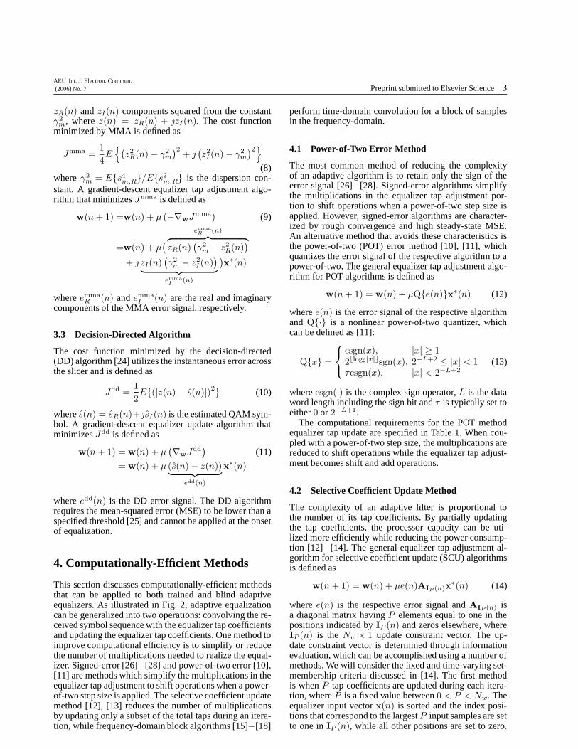
Fig. 1. Multirate system model for a decision feedback equalizer.
[8], blind decision feedback equalization (DFE) was cho-sen over trained equalization. In field tests conducted byHDTV manufacturers, the blind DFE achieved a lower er-ror rate and faster data acquisition than its trained counter-part in time-varying terrestrial channels [9].
In mobile communication channels, such as those formicrowave radio, high order filters are needed to achievechannel equalization. Equalizer tap adaptation is costly interms of power, memory, and computations and can beimpractical for mobile units. In this paper, we investigatecomputationally-efficient methods for blind DFEs, whichreduce the complexity and power requirements of blindequalization algorithms while maintaining their steady-state characteristics for QAM signals. These include thepower-of-two error [10], [11], selective coefficient update(also partial update) [12]−[14], and frequency-domainblock methods [15]−[18]. A novel radius-directed stop-and-go method is introduced, which selectively updatesthe equalizer tap coefficients based on the equalizer outputradius. This concept was conceived by Banovic et. al. in[19] for linear equalizers, where it was termed the se-lective update method. In this reformulation for DFEs,criteria is given for selection of the static bound pa-rameter, analysis is provided for adjustment probabilityand transient/steady-state performance, and a modifiedmethod is proposed to reduce hardware complexity. In ad-dition, a new activation/de-activation method based on theequalizer output radius is utilized to control the feedbackequalizer (FBE) of the DFEs. Simulation studies for blindDFEs employing the discussed methods are performedover empirically derived cable and microwave channelsand for Ricean fading channels.
2. Fractionally-Spaced System Model
In this section, a signal model is constructed for the T/2-spaced single-input single-output (SISO) baseband com-munication system for a DFE, where T is the symbol pe-riod and 1/T is the baud rate. A multirate model of thesystem is illustrated in Fig. 1, where the index ‘n’ de-notes T -spaced quantities while ‘k’ denotes T/2-spacedquantities. A T -spaced source symbol s(n) is transmittedthrough a pulse-shaping filter and modulated onto a T/2-spaced propagation channel, whose impulse response is
2 Preprint submitted to Elsevier ScienceAEU Int. J. Electron. Commun.
(2006) No. 7
given by the finite series {ck}Nc−1k=0 , where Nc is the chan-
nel length. This corresponds to the Nc × 1 channel im-pulse response vector of c = [c0, c1, . . . , cNc−1]
T where(·)T is the transpose operator and the channel is station-ary (a time-varying channel can be used as long as itdoes not vary faster than can be tracked by the equaliza-tion algorithm). The source symbol is a random variablethat is independent and identically distributed (i.i.d.) withzero mean and variance σ2
s = E{|s(n)|2} and is drawnfrom a finite alphabet, which is given by the finite set{sm = sm,R + sm,I}M
m=1 for an M -QAM constellation,where E{·} is the expectation operator and the subscriptsR and I denote the magnitude of the real and imaginaryquantities, respectively.
The received T/2-spaced input signal u(k) is corruptedby ISI and the additive white Gaussian noise (AWGN)signal v(k). The baseband receiver consists of a Nf -tap T/2-spaced feedforward equalizer (FFE) and a Nb-tap T -spaced FBE to form a nonlinear DFE, where theFFE removes the precursor ISI and the FBE removesthe postcursor ISI. The FFE and FBE tap-coefficientsare characterized by the finite series {fk}Nf−1
k=0 and{bk}Nb−1
k=0 , respectively, which correspond to the Nf × 1
vector f(n) =[f0(n), f1(n), . . . , fNf−1(n)
]Tand the
Nb × 1 vector b(n) = [b0(n), b1(n), . . . , bNb−1(n)]T , re-spectively. The output of the FFE is baud spaced andis formed by convolving the received T/2-spaced inputsignal sequence with the FFE tap coefficients. The T/2-spaced convolution matrix is constructed from the channelimpulse response vector and is defined as [2]
CFS =
c0
c1 c0
... c1 c0
cNc−1
... c1. . .
cNc−1
.... . . c0
cNc−1 c1
. . ....
cNc−1
(1)
where CFS is an (Nc + Nf − 1) × Nf matrix. The T -spaced convolution matrix is formed by the odd rows of(1) and is defined as
C =
c1 c0
c3 c2 c1 c0
...... c3 c2
. . .
cNc−1 cNc−2
......
. . . c1 c0
cNc−1 cNc−2 c3 c2
. . ....
...cNc−1 cNc−2
(2)where C is a P × Nf matrix andP = b(Nc + Nf − 1)/2c. The regressor vector ofFFE input samples is comprised of the previous Nf
received T/2-spaced samples and is defined as
u(n) = CT s(n) + v(n) (3)
where s(n) = [s(n), s(n − 1), . . . , s(n − P + 1)]T
is the P × 1 transmitted source symbol vector andv(n) = [v0(n), v1(n), . . . , vNf−1(n)]T is the Nf × 1vector of AWGN samples. The FFE output is decimatedby a factor of two and is defined as
y(n) = uT (n)f(n) = sT (n)Cf(n) + vT (n)f(n). (4)
The DFE output signal is defined as
z(n) = xT (n)w(n) = uT (n)f(n) − sT (n)b(n) (5)
where the Nw × 1 vectors x(n) =[uT (n), sT (n)
]Tand
w(n) =[fT (n),−bT (n)
]Tare the combined DFE in-
put regressor and tap coefficient vectors, respectively,while s(n) = [s(n), s(n − 1), . . . , s(n − Nb + 1)]
T isthe Nb × 1 regressor vector of past estimated symbolpoints and Nw = Nf + Nb.
The FBE does not exhibit noise enhancement since itutilizes past symbol estimates, which are assumed to becorrect [1]. When an incorrect symbol estimate is fed backto the feedback tapped delay line, there is a greater like-lihood of error propagation. Therefore, the SER must besufficiently low before the FBE is activated. Initially, theFFE is utilized to reduce the SER, while the FBE tap coef-ficients are fixed at zero. After the SER is sufficiently low,the FBE is activated to reduce the postcursor ISI.
3. Blind Equalization Algorithms
3.1 Constant Modulus Algorithm
The constant modulus algorithm (CMA) [20], [21]achieves channel equalization by penalizing the dispersionof the squared output modulus, |z(n)|2, from the constantγ2
c . The cost function minimized by CMA is defined as
Jcma =1
4E
{(|z(n)|2 − γ2
c
)2}
(6)
where γ2c = E{|sm|4}/E{|sm|2} is the dispersion con-
stant. A gradient-descent equalizer tap adjustment algo-rithm that minimizes Jcma is defined as
w(n + 1) = w(n) + µ (−∇wJcma) (7)
= w(n) + µ z(n)(γ2
c − |z(n)|2)
︸ ︷︷ ︸
ecma(n)
x∗(n)
where µ is a positive stepsize, ∇w is the gradient operatorwith respect to the elements of vector w, ecma(n) is theCMA error signal, and (·)∗ denotes complex conjugation.
3.2 Multimodulus Algorithm
The multimodulus algorithm (MMA) [22], [23] achieveschannel equalization by penalizing the dispersion of
AEU Int. J. Electron. Commun.(2006) No. 7 Preprint submitted to Elsevier Science 3
zR(n) and zI(n) components squared from the constantγ2
m, where z(n) = zR(n) + zI(n). The cost functionminimized by MMA is defined as
Jmma =1
4E
{(z2
R(n) − γ2m
)2+
(z2
I (n) − γ2m
)2}
(8)where γ2
m = E{s4m,R}/E{s2
m,R} is the dispersion con-stant. A gradient-descent equalizer tap adjustment algo-rithm that minimizes Jmma is defined as
w(n + 1) =w(n) + µ (−∇wJmma) (9)
=w(n) + µ(
emma
R (n)︷ ︸︸ ︷
zR(n)(γ2
m − z2R(n)
)
+ zI(n)(γ2
m − z2I (n)
)
︸ ︷︷ ︸
emma
I(n)
)x∗(n)
where emmaR (n) and emma
I (n) are the real and imaginarycomponents of the MMA error signal, respectively.
3.3 Decision-Directed Algorithm
The cost function minimized by the decision-directed(DD) algorithm [24] utilizes the instantaneous error acrossthe slicer and is defined as
Jdd =1
2E{(|z(n) − s(n)|)2} (10)
where s(n) = sR(n)+sI (n) is the estimated QAM sym-bol. A gradient-descent equalizer update algorithm thatminimizes Jdd is defined as
w(n + 1) = w(n) + µ(∇wJdd
)(11)
= w(n) + µ (s(n) − z(n))︸ ︷︷ ︸
edd(n)
x∗(n)
where edd(n) is the DD error signal. The DD algorithmrequires the mean-squared error (MSE) to be lower than aspecified threshold [25] and cannot be applied at the onsetof equalization.
4. Computationally-Efficient Methods
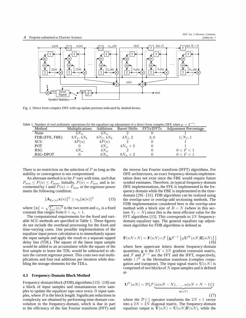
This section discusses computationally-efficient methodsthat can be applied to both trained and blind adaptiveequalizers. As illustrated in Fig. 2, adaptive equalizationcan be generalized into two operations: convolving the re-ceived symbol sequence with the equalizer tap coefficientsand updating the equalizer tap coefficients. One method toimprove computational efficiency is to simplify or reducethe number of multiplications needed to realize the equal-izer. Signed-error [26]−[28] and power-of-two error [10],[11] are methods which simplify the multiplications in theequalizer tap adjustment to shift operations when a power-of-two step size is applied. The selective coefficient updatemethod [12], [13] reduces the number of multiplicationsby updating only a subset of the total taps during an itera-tion, while frequency-domain block algorithms [15]−[18]
perform time-domain convolution for a block of samplesin the frequency-domain.
4.1 Power-of-Two Error Method
The most common method of reducing the complexityof an adaptive algorithm is to retain only the sign of theerror signal [26]−[28]. Signed-error algorithms simplifythe multiplications in the equalizer tap adjustment por-tion to shift operations when a power-of-two step size isapplied. However, signed-error algorithms are character-ized by rough convergence and high steady-state MSE.An alternative method that avoids these characteristics isthe power-of-two (POT) error method [10], [11], whichquantizes the error signal of the respective algorithm to apower-of-two. The general equalizer tap adjustment algo-rithm for POT algorithms is defined as
w(n + 1) = w(n) + µQ{e(n)}x∗(n) (12)
where e(n) is the error signal of the respective algorithmand Q{·} is a nonlinear power-of-two quantizer, whichcan be defined as [11]:
where csgn(·) is the complex sign operator, L is the dataword length including the sign bit and τ is typically set toeither 0 or 2−L+1.
The computational requirements for the POT methodequalizer tap update are specified in Table 1. When cou-pled with a power-of-two step size, the multiplications arereduced to shift operations while the equalizer tap adjust-ment becomes shift and add operations.
4.2 Selective Coefficient Update Method
The complexity of an adaptive filter is proportional tothe number of its tap coefficients. By partially updatingthe tap coefficients, the processor capacity can be uti-lized more efficiently while reducing the power consump-tion [12]−[14]. The general equalizer tap adjustment al-gorithm for selective coefficient update (SCU) algorithmsis defined as
w(n + 1) = w(n) + µe(n)AIP (n)x∗(n) (14)
where e(n) is the respective error signal and AIP (n) isa diagonal matrix having P elements equal to one in thepositions indicated by IP (n) and zeros elsewhere, whereIP (n) is the Nw × 1 update constraint vector. The up-date constraint vector is determined through informationevaluation, which can be accomplished using a number ofmethods. We will consider the fixed and time-varying set-membership criteria discussed in [14]. The first methodis when P tap coefficients are updated during each itera-tion, where P is a fixed value between 0 < P < Nw. Theequalizer input vector x(n) is sorted and the index posi-tions that correspond to the largest P input samples are setto one in IP (n), while all other positions are set to zero.
4 Preprint submitted to Elsevier ScienceAEU Int. J. Electron. Commun.
(2006) No. 7
Fig. 2. Direct form complex DFE with tap update portions indicated by dashed-boxes.
Table 1. Number of real arithmetic operations for the equalizer tap adjustment of a direct form complex DFE when µ = 2−n.
There is no restriction on the selection of P as long as thestability or convergence is not compromised.
An alternate method is to let P vary with time, such thatPmin ≤ P (n) ≤ Pmax. Initially, P (n) = Pmin and is in-cremented by 1 until P (n) = Pmax or the regressor powermeets the following condition:
‖AIP (n)x(n)‖2 ≥ αp‖x(n)‖2 (15)
where ‖x‖ =√∑
i |xi|2 is the two norm and αp is a fixedconstant that ranges from 0 < αp < 1.
The computational requirements for the fixed and vari-able SCU methods are specified in Table 1. These figuresdo not include the overhead processing for the fixed andtime-varying cases. One possible implementation of theequalizer input power calculation is to immediately squarethe input sample and apply the result to a separate tappeddelay line (TDL). The square of the latest input samplewould be added to an accumulator while the square of thefirst sample to leave the TDL would be subtracted to ob-tain the current regressor power. This costs two real multi-plications and four real additions per iteration while dou-bling the storage elements for the TDLs.
4.3 Frequency-Domain Block Method
Frequency-domain block (FDB) algorithms [15]−[18] usea block of input samples and instantaneous error sam-ples to update the equalizer taps once every B input sam-ples, where B is the block length. Significant reductions incomplexity are obtained by performing time-domain con-volution in the frequency-domain, which is due in partto the efficiency of the fast Fourier transform (FFT) and
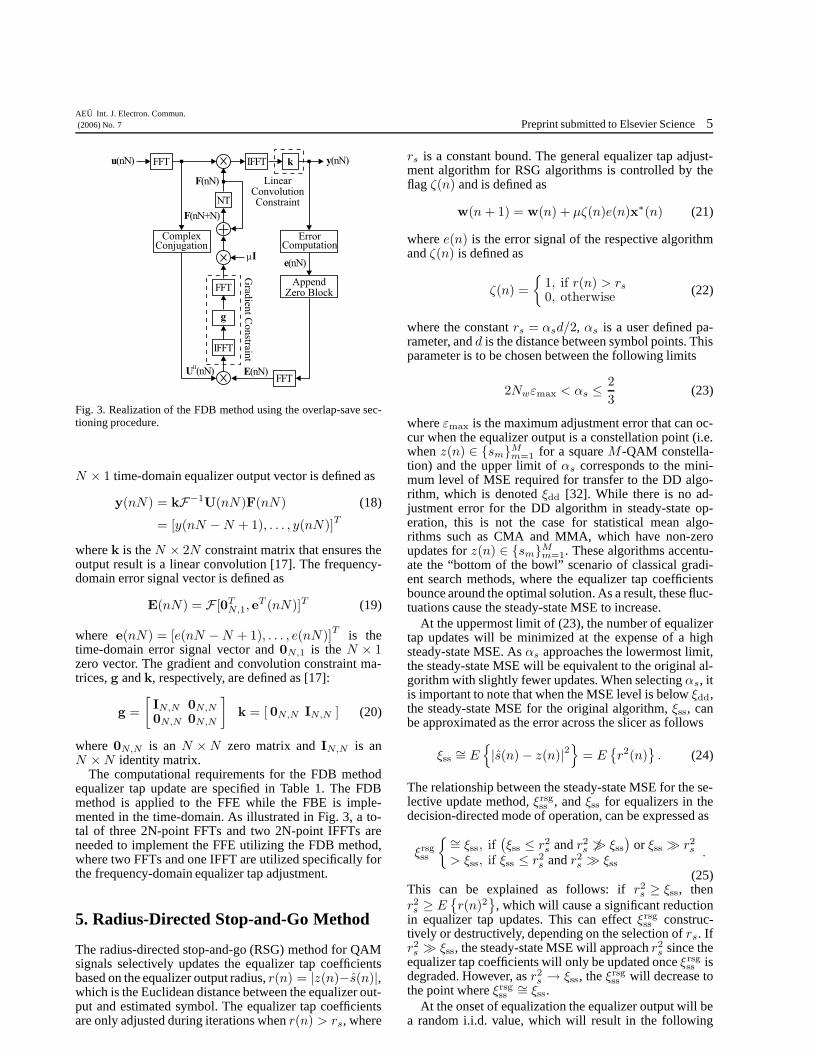
the inverse fast Fourier transform (IFFT) algorithms. ForDFE architectures, an exact frequency-domain implemen-tation does not exist since the FBE would require futuresymbol estimates. Therefore, in typical frequency-domainDFE implementations, the FFE is implemented in the fre-quency domain while the FBE is implemented in the time-domain [29]−[31]. FDB algorithms can be realized usingthe overlap-save or overlap-add sectioning methods. TheFDB implementation considered here is the overlap-savemethod with a block size of B = N (where in this sec-tion Nf = N ) since this is the most efficient value for theFFT algorithms [15]. This corresponds to 2N frequency-domain equalizer taps. The general equalizer tap adjust-ment algorithm for FDB algorithms is defined as
F(nN+N) = F(nN)+F{gF−1
{µUH (nN)E(nN)
}}
(16)where here uppercase letters denote frequency-domainquantities, g is the 2N × 2N gradient constraint matrix,and F and F−1 are the FFT and the IFFT, respectively,while (·)H is the Hermation transform (complex conju-gation and transpose). The input signal matrix U(nN) iscomprised of two blocks of N input samples and is definedas
UT (nN) = D{F [u(nN − N), . . . , u(nN + N − 1)]︸ ︷︷ ︸
u(nT )
}
(17)where the D {·} operator transforms the 2N × 1 vectorinto a 2N × 2N diagonal matrix. The frequency-domainequalizer output is Y(nN) = U(nN)F(nN), while the
AEU Int. J. Electron. Commun.(2006) No. 7 Preprint submitted to Elsevier Science 5
Fig. 3. Realization of the FDB method using the overlap-save sec-tioning procedure.
N × 1 time-domain equalizer output vector is defined as
y(nN) = kF−1U(nN)F(nN) (18)
= [y(nN − N + 1), . . . , y(nN)]T
where k is the N × 2N constraint matrix that ensures theoutput result is a linear convolution [17]. The frequency-domain error signal vector is defined as
E(nN) = F [0TN,1, e
T (nN)]T (19)
where e(nN) = [e(nN − N + 1), . . . , e(nN)]T is the
time-domain error signal vector and 0N,1 is the N × 1zero vector. The gradient and convolution constraint ma-trices, g and k, respectively, are defined as [17]:
g =
[
IN,N 0N,N
0N,N 0N,N
]
k = [ 0N,N IN,N ] (20)
where 0N,N is an N × N zero matrix and IN,N is anN × N identity matrix.
The computational requirements for the FDB methodequalizer tap update are specified in Table 1. The FDBmethod is applied to the FFE while the FBE is imple-mented in the time-domain. As illustrated in Fig. 3, a to-tal of three 2N-point FFTs and two 2N-point IFFTs areneeded to implement the FFE utilizing the FDB method,where two FFTs and one IFFT are utilized specifically forthe frequency-domain equalizer tap adjustment.
5. Radius-Directed Stop-and-Go Method
The radius-directed stop-and-go (RSG) method for QAMsignals selectively updates the equalizer tap coefficientsbased on the equalizer output radius, r(n) = |z(n)−s(n)|,which is the Euclidean distance between the equalizer out-put and estimated symbol. The equalizer tap coefficientsare only adjusted during iterations when r(n) > rs, where
rs is a constant bound. The general equalizer tap adjust-ment algorithm for RSG algorithms is controlled by theflag ζ(n) and is defined as
w(n + 1) = w(n) + µζ(n)e(n)x∗(n) (21)
where e(n) is the error signal of the respective algorithmand ζ(n) is defined as
ζ(n) =
{
1, if r(n) > rs
0, otherwise(22)
where the constant rs = αsd/2, αs is a user defined pa-rameter, and d is the distance between symbol points. Thisparameter is to be chosen between the following limits
2Nwεmax < αs ≤ 2
3(23)
where εmax is the maximum adjustment error that can oc-cur when the equalizer output is a constellation point (i.e.when z(n) ∈ {sm}M
m=1 for a square M -QAM constella-tion) and the upper limit of αs corresponds to the mini-mum level of MSE required for transfer to the DD algo-rithm, which is denoted ξdd [32]. While there is no ad-justment error for the DD algorithm in steady-state op-eration, this is not the case for statistical mean algo-rithms such as CMA and MMA, which have non-zeroupdates for z(n) ∈ {sm}M
m=1. These algorithms accentu-ate the “bottom of the bowl” scenario of classical gradi-ent search methods, where the equalizer tap coefficientsbounce around the optimal solution. As a result, these fluc-tuations cause the steady-state MSE to increase.
At the uppermost limit of (23), the number of equalizertap updates will be minimized at the expense of a highsteady-state MSE. As αs approaches the lowermost limit,the steady-state MSE will be equivalent to the original al-gorithm with slightly fewer updates. When selecting αs, itis important to note that when the MSE level is below ξdd,the steady-state MSE for the original algorithm, ξss, canbe approximated as the error across the slicer as follows
ξss∼= E
{
|s(n) − z(n)|2}
= E{r2(n)
}. (24)
The relationship between the steady-state MSE for the se-lective update method, ξrsg
ss , and ξss for equalizers in thedecision-directed mode of operation, can be expressed as
ξrsgss
{∼= ξss, if(ξss ≤ r2
s and r2s 6� ξss
)or ξss � r2
s
> ξss, if ξss ≤ r2s and r2
s � ξss.
(25)This can be explained as follows: if r2
s ≥ ξss, thenr2s ≥ E
{r(n)2
}, which will cause a significant reduction
in equalizer tap updates. This can effect ξrsgss construc-
tively or destructively, depending on the selection of rs. Ifr2s � ξss, the steady-state MSE will approach r2
s since theequalizer tap coefficients will only be updated once ξrsg
ss isdegraded. However, as r2
s → ξss, the ξrsgss will decrease to
the point where ξrsgss
∼= ξss.At the onset of equalization the equalizer output will be
a random i.i.d. value, which will result in the following
6 Preprint submitted to Elsevier ScienceAEU Int. J. Electron. Commun.
(2006) No. 7
equalizer update probability:
Pr[update] =d2 − (αsd/2)2π
d2= 1 − α2
sπ
4. (26)
This probability decreases as the equalizer adapts andreaches a minimum when the equalizer is in steady-state operation. During the initial stages of adapta-tion, E {r(n)} � rs causing the equalizer taps to beupdated frequently. This allows the respective algo-rithm to maintain its transient characteristics. As theE
{r(n)2
}→ ξss ∨ E {r(n)} → rs, the equalizer is in
steady-state operation and the number of equalizer tap up-dates will be at a minimum. If the channel should experi-ence sudden changes, the MSE will increase and the pro-cess will repeat.
While the RSG method reduces the number of equalizertap adjustments, there are no reductions in the hardwareresources needed for implementation. The RSG methodcan be modified to reduce the hardware complexity bycombining it with methods that simplify the multipli-cations in the tap coefficient update, such as the POTmethod. Here we propose retaining the first two leadingones of the error signal, which we term the double power-of-two (DPOT) method. This is proposed to improve theaccuracy of the error signal estimate over the POT method,while minimizing the added hardware complexity overthat method. The general equalizer tap adjustment algo-rithm for RSG-DPOT algorithms is defined as
w(n + 1) = w(n) + µζ(n)edpot(n)x∗(n) (27)
where edpot(n) = Q {e(n)} + Q {e(n) − Q {e(n)}},e(n) is the error signal of the respective algorithm andQ{·} is the nonlinear power-of-two quantizer that wasdefined in (13) for the POT method.
The computational requirements for the RSG and RSG-DPOT methods are specified in Table 1. The RSG methodmaintains the same hardware complexity but reduces thenumber of equalizer tap adjustments and hence, the num-ber of computations. However, in addition to reducingthe number of equalizer tap adjustments, the RSG-DPOTmethod reduces the equalizer tap adjustment to shift andadd operations when a power-of-two step size is applied.The calculation of r(n) requires two real multiplications,three real additions and one real square root. However, ifthe operand precision is sufficient, r2(n) can be utilizedto determine whether to adjust the equalizer taps, whicheliminates the square root function. Alternatively, a look-up-table (LUT) could be utilized to implement the squareroot function.
6. Simulation Study
This section presents simulation results forcomputationally-efficient methods applied to CMA-and MMA-based DFEs. The algorithms are simulatedover empirically derived cable and microwave channelsfrom the Signal Processing Information Base (SPIB,located: http://spib.rice.edu/) and multi-tapRicean fading channels. The simulation environment
Calculate r(n)
r(n) < d/3
count < r th
count > 0
count=count-1
Yes
No
Yes
Turn off DFE
Yes
No
No
count=count+1 Turn on DFE
Fig. 4. DFE activation and de-activation flow chart.
consists of a T/2-spaced channel in cascade with a 54-tapDFE consisting of an 18-tap T/2-spaced FFE and a36-tap T-spaced FBE, where the channel, FFE, and FBEare modeled as complex FIR filters. The source symbolsequence is randomly generated using an i.i.d. process andis drawn from a normalized square QAM constellation.The received equalizer input samples are generated byconvolving the source sequence with the channel impulseresponse and adding AWGN.
The DFE is controlled by the activation/de-activationmethod illustrated in Fig. 4, which utilizes r(n) to de-termine whether to activate or de-activate the FBE of theDFE. At the onset of equalization, the FFE is initializedwith a dual center spike of 1/
√2 and the FBE is fixed at
zero, while the variable count is set to zero. The FFE isadapted blindly using CMA or MMA. During an iteration,if r(n) < d/3, count will increment by one while lessthan the user defined threshold value rth, where d/3 corre-sponds to ξdd [32]. Once count reaches rth, the FBE willbe activated and count will saturate at rth. The adapta-tion of the DFE is switched to the DD algorithm. How-ever, if r(n) > d/3, count will decrement by one whilegreater than zero. If the DFE is in the active state, oncecount reaches zero, the DFE will deactivate. The FFEwill be adapted blindly using CMA or MMA and the FBEwill be fixed at zero, while count will saturate at zero.
The first set of simulation studies compare the stan-dard computationally-efficient methods of FDB, SCU andPOT with RSG for CMA- and MMA-based DFEs. In thesesimulations, the algorithms are compared with the FDBalgorithm since its performance is equivalent to that ofthe original DFE. The second set of simulations com-pare RSG-based methods that reduce the number of com-putations and hardware complexity of the original RSGmethod. The RSG method is combined with the SCU,POT, and DPOT methods for CMA- and MMA-basedDFEs, where each method is compared to the originalRSG method. The simulation parameters for each methodare as follows: αp = 0.875 for SCU, L = 16 and τ = 0
for POT, and αs = 2 · 10−3/2d−1 for RSG, while rth wasset to 63 for all DFEs. Quantitative simulation results arepresented for the steady-state MSE, the average time-to-
AEU Int. J. Electron. Commun.(2006) No. 7 Preprint submitted to Elsevier Science 7
convergence (TTC), the equalizer adjustment percentagefor RSG-based DFEs in transient and steady-state opera-tion (TR/SS), and the tap coefficient update (TCU) per-centage for SCU-based DFEs. The MSE curves are ob-tained by averaging the instantaneous squared-error acrossthe slicer over 300 realizations. The TTC is calculated asthe number of symbols needed to reach 90% of the steady-state MSE while ξss is the average MSE over the the final10% of the estimated symbol sequence.
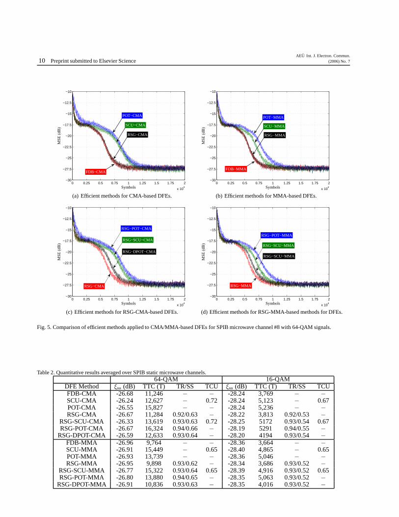
Microwave channel simulations were conducted forCMA- and MMA-based DFEs over SPIB microwavechannels #1, 2, 4, 5, 8− 10 and #1, 2, 4− 6, 8− 10, re-spectively, for 64- and 16-QAM signals with a signal-to-noise ratio (SNR) of 35dB, where each channel consistsof 208-300 complex T/2-spaced taps. These modulationschemes were chosen since they are the largest schemesapplied to the data carriers in an orthogonal frequencydivision multiplex (OFDM) frame for terrestrial DVB.Step sizes of µ = 2−11 and µ = 2−10 were applied to theequalizer tap adjustment for 64- and 16-QAM signals, re-spectively. Simulation results are illustrated for channel #8in Fig. 5 for CMA- and MMA-based DFEs with 64-QAM,which are representative of the typical results obtained.Quantitative results averaged over all channels are given inTable 2. On average, in comparison with the FDB method,the RSG method achieves a slightly longer TTC, while theSCU and POT methods require significantly more sym-bols to converge for CMA- and MMA-based DFEs. Allmethods are able to achieve similar steady-state MSE val-ues. As expected, in transient operation, the equalizer ad-justment percentage of RSG-based DFEs is high at above91% for both 64- and 16-QAM, respectively, while insteady-state operation, the percentage is below 67% and56%. Less than 73% of the DFE tap coefficients are up-dated for SCU-based DFEs. Of the RSG-based DFEs, theRSG-DPOT method obtains a slightly longer TTC whilemaintaining the properties of the RSG-based DFEs. Theresults for CMA- and MMA-based DFEs for microwavechannels indicate similar transient and steady-state char-acteristics for the efficient methods under consideration.Therefore, without loss of generality, the remaining simu-lations will be for MMA-based DFEs.
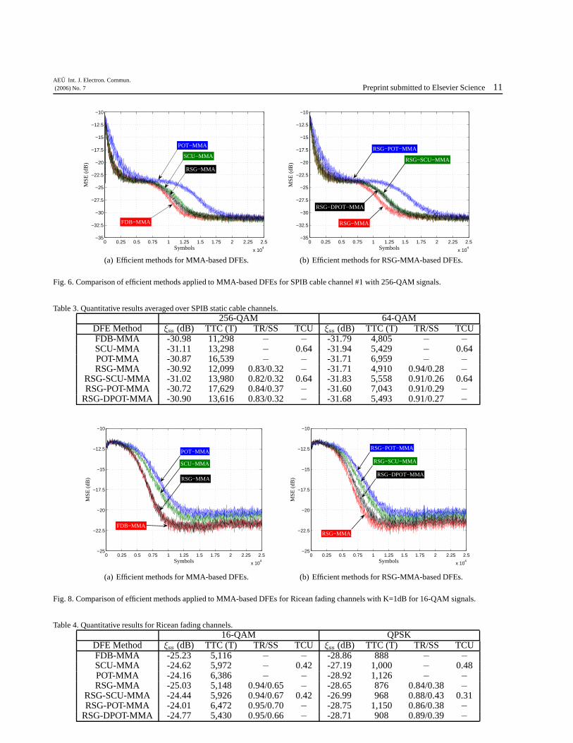
Cable channel simulations were conducted for MMA-based DFEs over SPIB cable channels #1, 2 for 256-and 64-QAM signals with an SNR of 40dB, where eachchannel consists of 128 complex T/2-spaced taps. Thesemodulation schemes were selected since they are thelargest square schemes utilized for DVB-C. Step sizes ofµ = 2−12 and µ = 2−11 were applied to the equalizer tapadjustment for 256- and 64-QAM signals, respectively.Simulation results are illustrated for channel #1 in Fig. 6for 256-QAM, which are representative of the typical re-sults obtained. Quantitative results averaged over all ca-ble channels are given in Table 3. On average, the RSGmethod achieves a slightly longer TTC, while the SCUand POT methods require significantly more symbols toconverge. All methods are able to achieve similar steady-state MSE values. The equalizer adjustment percentage forRSG-based DFEs in transient operation is above 81% and90% for 256- and 64-QAM, respectively, while in steady-state operation, the percentage is below 38% and 30%.
Fig. 7. Ricean fading channel model used for simulations.
For SCU-based DFEs, 64% of the DFE tap coefficientswere updated. Of the RSG-based DFEs, the RSG-DPOTmethod obtains a slightly longer TTC while once againmaintaining the properties of the RSG-based DFEs.
Fading channel simulations were conducted for MMA-based DFEs over a 5-tap Ricean fading channel as illus-trated in Fig. 7 for 16-QAM and quadrature phase shiftkeying (QPSK) signals with a SNR of 40dB, where g(k)is the Rayleigh fading process and K is the rice factorwhich was set to K = 1dB, K = 2.5dB, and K = 5dB.The Rayleigh fading processes applied to the channel tapswere independent, randomly initialized, and simulated us-ing the normalized low-pass fading process of Jakes’ sim-ulator [33]. The fading parameters were selected using theIMT-2000 evaluation methodology for 3G wireless com-munications [34], where the carrier and symbol frequen-cies were set to 2GHz and 4.096MBaud, respectively.The mobile transceiver was moving at a velocity of 12km/h to represent a person jogging. Step sizes of µ = 2−9
and µ = 2−6 were applied to the equalizer tap adjust-ment for 16-QAM and QPSK signals, respectively. Sim-ulation results are illustrated in Fig. 8 for 16-QAM withK = 1dB. Quantitative results are given in Table 4. Onaverage, for 16-QAM signals, the RSG method achievesnearly identical TTC and steady-state MSE values, whilethe SCU and POT methods obtain a significantly largerTTC and a higher steady-state MSE, where the perfor-mance of the POT method is the worst for both. For QPSK,the steady-state MSE of the SCU method is nearly iden-tical to that of the original while the TTC properties re-main the same for all methods. The equalizer adjustmentpercentage for RSG-based DFEs in transient operation isabove 93% and 83% for 16-QAM and QPSK, respectively,while in steady-state operation, the percentage is below71% and 44%. For SCU-based DFEs, 42% of the DFEtap coefficients were updated for 16-QAM and 48% forQPSK. Of the RSG-based DFEs, the RSG-DPOT methodobtains a slightly longer TTC and slightly higher steady-state MSE, while the RSG-SCU and RSG-POT methodsobtain a significantly higher steady-state MSE and longerTTC for 16-QAM signals..
7. Conclusion
This paper investigated computationally-efficient methodsfor blind DFEs that reduced the complexity and power re-quirements of blind equalization algorithms while main-taining their steady-state characteristics for complex sig-nals. New computationally-efficient methods methodswere proposed that reduced the number of computations
8 Preprint submitted to Elsevier ScienceAEU Int. J. Electron. Commun.
(2006) No. 7
and hardware requirements for blind DFEs, mainly theRSG and RSG-DPOT methods. Simulation results forstatic cable and microwave channels and for Ricean fad-ing channels indicate that the new methods maintain thetransient and steady-state performance of the original al-gorithm, while reducing their complexity.
Acknowledgement
The authors wish to thank Harb Abdulhamid and Raymond Lee fortheir comments and suggestions during discussions on fading chan-nels and the proposed methods.
References
[1] Qureshi, S. U. H.: Adaptive equalization. Proceedings of theIEEE 73 (September 1985), 1349–1387.
[2] Johnson, C. R.; Schniter, P.; Endres, T. J.; Behm, J. D.; Brown,D. R.; Casas, R. A.: Blind equalization using the constantmodulus criterion: a review. Proceedings of the IEEE 86(1998), 1927–1950.
[3] Shynk, J. J.; Gooch, R. P.; Krishnamurthy, G.; Chan, C. K.: Acomparative performance study of several blind equalizationalgorithms. SPIE 1565 (1991), 102–117.
[4] Werner, J.-J.; Yang, J.; Harman, D.; Dumont, G. A.: Blindequalization for broadband access. IEEE Comm. Magazine(1999), 87–93.
[5] Digital video broadcasting (DVB); framing structure, channelcoding and modulation for 11/12 GHz satellite services. ATSCStandard Revision A. ETSI, 1998.
[6] Digital video broadcasting (DVB); framing structure, channelcoding and modulation for cable systems. ATSC Standard Re-vision A. ETSI, 2004.
[8] Transmission measurement and compliance for digital televi-sion. ATSC Standard Revision A. ATSC, 2000.
[9] Ghosh, M.: Blind decision feedback equalization for terrestrialtelevision receivers. Proc. of the IEEE 86 (1998), 2070–2081.
[10] Allred, D. J.; Yoo, H.; Krishnan, V.; Huang, W.; Anderson,D. V.: A novel high performance distributed arithmetic adap-tive filter implementation on an fpga. Proc. ICASSP’04, Mon-real, Quebec, May 2004. 161–164.
[11] Eweda, E.: Convergence analysis and design of adaptive fil-ter with finite power-of-two quantized error. IEEE Trans. onCircuits and Systems II 39 (February 1992), 113–115.
[12] Gollamudi, S.; Kapoor, S.; Nagaraj, S.; Huang, Y.-F.: Set-membership adaptive equalization and an updator-shared im-plementation for multiple channel communications systems.IEEE Trans. on Acoustics, Speech, and Signal Processing 46(1998), 2372 – 2385.
[13] Godavarti, M.; Hero, A. O.: Partial update LMS algorithms.IEEE Trans. on Signal Processing 53 (2005), 2382– 2399.
[14] Werner, S.; de Campos, M. L. R.; Diniz, P. S. R.: Partial-update NLMS algorithms with data-selective updating. IEEETrans. on Signal Processing 52 (2004), 938–949.
[15] Clark, G. A.; Mitra, S. K.; Parker, S. R.: Block implementationof adaptive digital filters. IEEE Trans. on Circuits & SystemsCAS-28 (1981), 584–592.
[17] Shynk, J. J.: Frequency-domain and multirate adaptive filter-ing. IEEE Signal Processing Magazine (1992), 14 – 37.
[18] Shynk, J. J.; Gooch, R. P.; Witmer, D. P.; Chjan, C. K.; Ready,M. J.: Adaptive equalization using multirate filtering tech-niques. Proc. Asilomar, Pacific Grove, CA, 1991. 756–762.
[19] Banovic, K.; Lee, R.; Abdel-Raheem, E.; Khalid, M. A. S.:Computationally-efficient methods for blind adaptive equal-ization. Proc. Int. Midwest Symposium on Circuits & Sys-tems, Cincinnati, Ohio, August 2005. 341–344.
[20] Godard, D. N.: Self-recovering equalization and carrier track-ing in two-dimensional data communication systems. IEEETrans. on Comm. 28 (November 1980), 1867–1875.
[21] Treichler, J. R.; Agee, B. G.: A new approach to multipath cor-rection of constant modulus signals. IEEE Trans. on Acoust.,Speech, Signal Processing ASSP-31 (April 1983), 459–472.
[22] Yang, J.; Werner, J.-J.; Dumont, G. A.: The multimodulusblind equalization algorithm. Proc. Int’l Conference on DigitalSignal Processing, July 1997. 127–130.
[23] Yang, J.; Werner, J.-J.; Dumont, G. A.: The multimodulusblind equalization and its generalized algorithms. IEEE Jour-nal on selected areas in comm. 20 (June 2002), 997–1015.
[24] Picchi, G.; Prati, G.: Blind equalization and carrier recov-ery using a “stop and go” decision directed algorithm. IEEETrans. on Comm. 35 (September 1987), 877–887.
[25] Castro, F. C. C. D.; Castro, M. C. F. D.; Arantes, D. S.: Con-current blind deconvolution for channel equalization. Proc.Int’l Conference on Comm., June 2001. 366–371.
[26] Im, G.; Park, C.; Won, H.: A blind equalization with the signalgorithm for broadband access. IEEE Communication Letters5 (Feb. 2001).
[27] Brown, D. R.; Schniter, P.; Johnson, C. R.: Computationallyefficient blind equalization. Proc. Allerton Conf. on Com-munication, Control and Computing, Monticello, IL, October1997. 54–63.
[28] Schniter, P.; Johnson, C. R.: Dithered signed-error CMA: ro-bust, computationally efficient blind adaptive equalization.IEEE Trans. on Signal Processing 47 (June 1999), 1592–1603.
[29] Pancaldi, F.; Vitetta, G. M.: Frequency-domain equalizationfor dpace-time block-coded systems. IEEE Trans. on WirelessComm. 4 (November 2005), 2907–2916.
[30] Zhu, Y.; Letaief, K. B.: Single-carrier frequency-domainequalization with decision-feedback processing for time-reversal spacetime block-coded systems. IEEE Trans. onComm. 53 (July 2005), 1127–1131.
[31] Kim, D. K.; Park, P.: Adaptive self-orthogonalizing per-tonedecision feedback equalizer for single carrier modulations.IEEE Signal Processing Letters 13 (January 2006), 21–24.
[32] Banovic, K.; Abdel-Raheem, E.; Khalid, M. A. S.: A novelradius-adjusted approach for blind adaptive equalization.IEEE Signal Processing Letters 13 (January 2006), 37–40.
[33] Jakes, W. C.: Microwave mobile communications. Piscataway,New Jersey: IEEE Press, 1994.
[34] Evaluation Group ARIB IMT 2000 Study Committee: Evalu-ation methodology for IMT-2000 ratio transmission technolo-gies. ARIB (June 1998).
Kevin Banovic received his B.A.Sc. andM.A.Sc. degrees in electrical engineer-ing from the University of Windsor, On-tario, Canada, in 2003 and 2006, respec-tively. He is a candidate in the electri-cal and computer engineering Ph.D. pro-gram at the University of Toronto, Ontario,Canada. His research interests include thedesign and applications of signal process-ing microsystems, adaptive signal process-ing, high performance VLSI design and
field-programmable logic.
AEU Int. J. Electron. Commun.(2006) No. 7 Preprint submitted to Elsevier Science 9
Esam Abdel-Raheem received hisB.Sc. and M.Sc. degrees from Ain ShamsUniversity, Cairo, Egypt, in 1984 and1989, respectively, and Ph.D. degreefrom the University of Victoria, Canadain 1995, all in Electrical Engineering.Currently, he is an Associate Professor atUniversity of Windsor, Ontario, Canada.Dr. Abdel-Raheem’s research fields ofinterests are in digital signal processing,signal processing for communications,
and VLSI signal processing. He is a senior member of the IEEE anda member of the IEEE SPS tech. committee on Signal ProcessingEducation and IEEE CAS tech. committee on VLSI systems &applications. He has served as the technical program co-chair forIEEE ISSPIT 2004 & 2005.
Mohammed A.S. Khalid received thePh.D. degree in Computer Engineeringfrom the University of Toronto in 1999.He is an Assistant Professor in Electricaland Computer Engineering Department atthe University of Windsor. From 1999 to2003, he was a Senior Member of Techni-cal Staff in the Verification Acceleration R& D Group (formerly Quickturn), of Ca-dence Design Systems, based in San Jose,California. His research and development
interests are in architecture and CAD for field programmable chipsand systems, reconfigurable computing, digital system design andhardware description languages.
10 Preprint submitted to Elsevier ScienceAEU Int. J. Electron. Commun.
(2006) No. 7
0 0.25 0.5 0.75 1 1.25 1.5 1.75 2
x 104
−30
−27.5
−25
−22.5
−20
−17.5
−15
−12.5
−10
Symbols
MSE
(dB
)
POT−CMA
SCU−CMA
RSG−CMA
FDB−CMA
(a) Efficient methods for CMA-based DFEs.
0 0.25 0.5 0.75 1 1.25 1.5 1.75 2
x 104
−30
−27.5
−25
−22.5
−20
−17.5
−15
−12.5
−10
Symbols
MS
E (
dB)
POT−MMA
SCU−MMA
RSG−MMA
FDB−MMA
(b) Efficient methods for MMA-based DFEs.
0 0.25 0.5 0.75 1 1.25 1.5 1.75 2
x 104
−30
−27.5
−25
−22.5
−20
−17.5
−15
−12.5
−10
Symbols
MSE
(dB
)
RSG−POT−CMA
RSG−SCU−CMA
RSG−DPOT−CMA
RSG−CMA
(c) Efficient methods for RSG-CMA-based DFEs.
0 0.25 0.5 0.75 1 1.25 1.5 1.75 2
x 104
−30
−27.5
−25
−22.5
−20
−17.5
−15
−12.5
−10
Symbols
MS
E (
dB)
RSG−POT−MMA
RSG−SCU−MMA
RSG−SCU−MMA
RSG−MMA
(d) Efficient methods for RSG-MMA-based methods for DFEs.
Fig. 5. Comparison of efficient methods applied to CMA/MMA-based DFEs for SPIB microwave channel #8 with 64-QAM signals.