Dental Radiography Computed dental radiography: Evaluation of a new charge-coupled device-hased intraoral radiographie system Allan G. Farman*/William C. Scarfe*/David B, Schick**/Peter M. Rumack** Computed dental radiography is afilmless system of dental x-ray imaging. Il features multiple sensors with receptive areas and image quality that approach the size and resolution offilm. The system is able to match the uiility of film on levels such as multipie-.'iized images and printing output. It approaches ßim in qualit}- of image and diagnostic capacity. In features such as speed of image acquisition, reduction in radiation dose, retrievai of data, and organization and storage of images, the computed dental radiography system surpasses traditional x-ray film- (Quintessence Int ¡995:26:399-404.) Introduction Dental radiography based on charge-coupled device (CCD) technology permits the irrunediate display of an image in a large format that the patient can understand. Snch systems have the potential to expe- dite operative procedures such as endodontics and dental implant placement. If the selected exposure is incorrect, the error is apparent immediately and can be adjusted before further exposures are made. It elimin- ates the need for, and expense of, darkrooms, proees- sors, film, and processing solutions. Moreover, there is no movement of contaminated film packets around the office to the darkroom, A variety of CCD-based intraoral radiographie systems have received Food and Drug Administration approval for sale in the United States. These systems include RadioVisioGraphy (RVG) in the forms of RVG-S, RVG-Si, RVG-PC, and RVG-PCl {Trophy Radiologie): Flash Dent (Villa Sistemi Medicali); * University of Louisville, School of Dentistry, Louisville, Kentucky, " Schick Technologies, Ire, Long Island City, New York, Repritit requests: Dr Allan G, Farman, Professor and Head, Division of Radiology and Imagina Sdetices, University of Luiiisvilie, School of Dentistry, Louisville, Kentucky 40292, Dr Dayid B. Schick invented (he CDR systems, and he is chief executive officer of Schick Technologies, VIXA ( Dents pi y/Gendex); and the Sens-A-Ray (Re- gam), Sens-A-Ray has also been sold under the names Acu-Ray (New Image) and Insta-Ray (MedCam), Most recently, a new CCD-based system, computed dental radiography (CDR) {Schick Technologies), has been introduced to the market, A comparison of the available systems is provided in Table 1,''^ There are two major types of CCD for intraoral radiography: (I) those that use an optical couple to channel fluorescence, produced when incident x- radiation is produced in a scintillation screen, to a light-sensitive CCD, and (2) those that do not use an optical couple. The first type uses either a fiber-optic couple (RVG systems) or a series of lenses (Rash Dent). The addition of optics permits the use of CCDs with a smaller surface area than the object to be imaged because, unlike x-radiation, it is a simple matter to focus light. Additionally, optics allow the use of CCDs that are more sensitive to radiation damage, because glass that is translucent to light can be made resistant to the passage of x-radiation (eg, the fiber optics in the RVG systems is constructed from tungsten glass). The second group of commercially available in- traoral radiographie CCDs use "hardened" CCDs with a surface area sufficient to receive tbe whole image. The major advantage of these systems is the absence of optical distortion. Wlien a scintillator is present in these systems, it is painted directly onto the surface of the CCD chip. This generally results in Q u intesawioc Inluiiohongl—Vuluiiie -lutnber 6/1995 399
Transcript
Dental Radiography
Computed dental radiography: Evaluation of a new charge-coupleddevice-hased intraoral radiographie system
Allan G. Farman*/William C. Scarfe*/David B, Schick**/Peter M. Rumack**
Computed dental radiography is afilmless system of dental x-ray imaging. Il featuresmultiple sensors with receptive areas and image quality that approach the size and resolutionof film. The system is able to match the uiility of film on levels such as multipie-.'iizedimages and printing output. It approaches ßim in qualit}- of image and diagnosticcapacity. In features such as speed of image acquisition, reduction in radiation dose, retrievaiof data, and organization and storage of images, the computed dental radiography systemsurpasses traditional x-ray film- (Quintessence Int ¡995:26:399-404.)
Introduction
Dental radiography based on charge-coupled device(CCD) technology permits the irrunediate display ofan image in a large format that the patient canunderstand. Snch systems have the potential to expe-dite operative procedures such as endodontics anddental implant placement. If the selected exposure isincorrect, the error is apparent immediately and can beadjusted before further exposures are made. It elimin-ates the need for, and expense of, darkrooms, proees-sors, film, and processing solutions. Moreover, there isno movement of contaminated film packets around theoffice to the darkroom,
A variety of CCD-based intraoral radiographiesystems have received Food and Drug Administrationapproval for sale in the United States. These systemsinclude RadioVisioGraphy (RVG) in the forms ofRVG-S, RVG-Si, RVG-PC, and RVG-PCl {TrophyRadiologie): Flash Dent (Villa Sistemi Medicali);
* University of Louisville, School of Dentistry, Louisville, Kentucky,
" Schick Technologies, Ire, Long Island City, New York,
Repritit requests: Dr Allan G, Farman, Professor and Head, Division ofRadiology and Imagina Sdetices, University of Luiiisvilie, School ofDentistry, Louisville, Kentucky 40292,
Dr Dayid B. Schick invented (he CDR systems, and he is chief executiveofficer of Schick Technologies,
VIXA ( Dents pi y/Gendex); and the Sens-A-Ray (Re-gam), Sens-A-Ray has also been sold under the namesAcu-Ray (New Image) and Insta-Ray (MedCam),Most recently, a new CCD-based system, computeddental radiography (CDR) {Schick Technologies),has been introduced to the market, A comparison ofthe available systems is provided in Table 1,''
There are two major types of CCD for intraoralradiography: (I) those that use an optical couple tochannel fluorescence, produced when incident x-radiation is produced in a scintillation screen, to alight-sensitive CCD, and (2) those that do not use anoptical couple. The first type uses either a fiber-opticcouple (RVG systems) or a series of lenses (RashDent). The addition of optics permits the use of CCDswith a smaller surface area than the object to be imagedbecause, unlike x-radiation, it is a simple matter tofocus light. Additionally, optics allow the use of CCDsthat are more sensitive to radiation damage, becauseglass that is translucent to light can be made resistantto the passage of x-radiation (eg, the fiber optics inthe RVG systems is constructed from tungsten glass).
The second group of commercially available in-traoral radiographie CCDs use "hardened" CCDswith a surface area sufficient to receive tbe wholeimage. The major advantage of these systems is theabsence of optical distortion. Wlien a scintillator ispresent in these systems, it is painted directly onto thesurface of the CCD chip. This generally results in
Q u intesawioc Inluiiohongl—Vuluiiie -lutnber 6/1995 399
Dental Radiography
Tabie 1 System approved for CCD intraoral radiography
System
RVG-S and RVG-PCiSens-A-Ray
VDCAFlash Dent
CDR
Film No. 0Film No. 1FUm No. 2
Sensitivearea (mm)
275X 182259X 173240X 180240 X 200240 X 300209 X 147346 X 192365 X 252350 X 220400 X 2404 1 0 x 3 1 0
Pixelmatrix
480 X 380576 X 385384 X 288480 X 400
436 X 306720 X 4007 6 0 x 5 2 4
N/AN/AN/A
Pixelsize {|im)
6 0 x 6 045 x 4 563 X 6350 X 5050 X 8548 x 4 848 x 4 848 x 4 8
N/AN / AN / A
Dynamicrange
8 bit8 bit8 bit8 bit
12 bit*
AnalogAnalogAnalog
Optics
YFS
NO
NOYES
YES
NONONO
* Displayed 8 bit.N/A = not applicable.
greater spatial resolution for the image; however, it issometimes accompanied by an increase in the back-ground haze or "noise."
The purpose of this paper is to present the salientfeatuTes of the new Schick CDR intraoral radiographiesystem.
Specifications
The CDR has three sensor sizes comparable to. butslightly smaller than, the corresponding film sizes 0, 1,2. Sensors may be used interchangeably as clinicalrequirements demand. The CDR size 0 and 2 sensorsare compared with size 2 film and the RVG-S andSens-A-Ray sensors in Fig 1. Paralleling holders havebeen developed to aid in the placement and posi-tioning of the sensors (Fig 2).
The CDR system is based on IBM-compatiblepersonal computer (PC) architecture. The system canbe operated with any IBM-compatible computer withan 80386, 80486, or Pentium microprocessor. An80486 processor with 4 megabytes of random-accessmemory is recommended as the minimum configura-tion. Proprietary software supports a super videographics adaptor (SVGA) graphics board and moni-tor. In addition to a PC-compatibie computer with anSVGA display, the CDR system includes a datatransfer module (DTM), aírame buffer, board, and oneor more intraoral sensors. The sensors plug into theDTM. The DTM provides the sensors with power and
timing signals. Image data are sent from the sensor tothe DTM in analog form. The DTM then converts theanalog signal to digital data, producing a 12-bit dataword for each pixel. These data are sent to thecomputer via a cable up to 20 ft long. The data aretemporarily stored in the frame buffer until they aretransferred to memory.
Proprietary software controls the image capture,storage, and enhancements. The software maintainsimage files, which can be stored on hard drive or anyother computer storage medium that the operatordesires. Roppy disk, digital audio tape, write onceread many (WORM) drive, or hard disk may be used asstorage medium. Additionally, the software supports a4-inch thermal printer for generation of hard copies.The images can be produced individually or as acomplete series. The patient's name, date of examina-tion, and notes may be added to the prints. Theiull-series output uses three frames to create fulldocumentation. For Hill-sized format output, a Laser-jet IV(Hewlett Packard) with a 2400 DPI upgrade canbe fitted-
Because the sensors generate large data files, theCDR software supports uncompressed storage, loss-less or lossy compression of the image data. Anuncompressed No. 2 sensor produces a 400-kb datafile. Lossless compression reduces the file size toapproximately 180 kb, and the lossy compressionproduces a 65 kb-file.
400 Quintessence International Volume 26, Numbñr
Dental Radiography
Fig 1 Sensors compared: ífe/í to right) Sens-A-Ray.RVG-S, CDR No. 2 sensor, CDR No. 0 sensor, and size 2conventional film.
Fig 2 (right) The CDR can be positioned with a parallelingdevice similar to those used for conventional film
Sensor description
Computed dental radiography sensors are approxi-mately 5 mm thick and are enclosed in a sealedaluminum casing. The active area of the sensorsextends to within 2 mm from each edge, A 3-footTeflon cable exits from the rear center ofthe sensor forattachment to the DTM, The sensor is impervious tocold sterilizing agents and may be immersed. Dispos-able sterile sheaths are provided for added protectionagainst cross contamination (Fig 3),
Image characteristics
Image quality for radiographs is determined by threefactors: spatial resolution, signal-to-noise ratio(SNR), and dynamic range, or contrast resolution.Resolution is a measure ofthe sharpness ofthe image,measured in line-pairs per millimeter (Ip/mm), Signal-to-noise ratio is a measure of how much deviation inbrightness exists in a uniformly exposed area of theimage. Dynamic range is the ratio ofthe exposure levelof the sensor from the least observable level to thehighest observable level. Dynamic range is usuallyexpressed as a logarithm ofthat ratio.
As a point of reference, a well-exposed Ultra-Speedftlm (Fastman Kodak) has high spatial resolution (± 16lp/mm), poor SNR (+ 35:1), and. when read underappropriate light, a very wide dynamic range. TheCDR sensors have a resolution of approximately 9lp/mm, a very high SNR of greater than 100:1 and a
Fig 3 Disposable double-bagged sleeves are used as abarrier to prevent cross contamination between patients.
dynamic range of 12 bits, displayed as 8 bits. Totranslate these ftgures into qualitative observations.CDR images tend to be less noisy ("cleaner") thanfilm and have less sharp features. The effective dynamicrange of digitai radiology systems is limited by thecontrast possibilities ofthe display systems. As men-tioned earlier, this output contrast resolution is gener-ally 8 bit. This problem may be overcome by providingsoftware fijnctions that allow the operator to expandthe contrast ofthe image being viewed.
Quinte -es. Number 6/1995 401
Dental Radiography
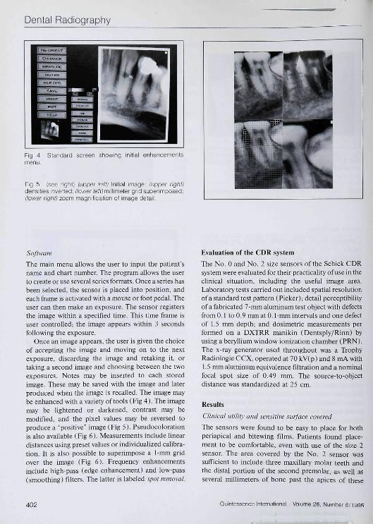
Fig 4 Standard screen showing initial enhancementsmenu.
The main menu allows the user to input the patient'sname and chart number. The program allows the userto create or use several series formats. Once a series hasbeen selected, the sensor is placed into position, andeach frame is activated with a mouse or foot pedal. Theuser can then make an exposure. The sensor registersthe image within a specified time. This time frame isuser controlled; the image appears within 3 secondsfollowing the exposure.
Once an image appears, the user is given the choiceof accepting the image and moving on to the nextexposure, discarding the image and retaking it, ortaking a second image and choosing between the twoexposures. Notes may be inserted to each storedimage. These may be saved with the image and laterproduced when the image is recalled. The image maybeenlianced with a variety of tools (Fig A). The imagemay be lightened or darkened, contrast may bemodified, and the pixel values may be reversed toproduce a "positive" image (Fig 5). Pseudocolorationis aJso available (Fig 6), Measurements include lineardistances using preset values or individualized calibra-tion. It is also possible to superimpose a 1-mm gridover the image (Fig 6). Frequency enhancementsinclude high pass (edge enhancement) and low-pass(smoothing) filters. The latter is labeled spot removal.
Evaluation of the CDR system
The No. 0 and No. 2 size sensors of the Schick CDRsystem were evaluated for their practicality of use in theclinical situation, including the useful image area.Laboratory tests carried out included spatial resolutionof a standard test pattern (Picker); detail perceptibilityof a fabricated 7-nun aluminum test object with defectsfrom 0.1 to 0.9 mm at 0.1mm intervals and one defectof 1.5 mm depth; and dosimetric measurements performed on a DXTRR manikin (Dentsply/Rinn) byusing a beryllium window ionization chamber (PRN),The x-ray generator used throughout was a TrophyRadiologie CCX, operated at 70 kV(p) and 8 mA with1.5 mm aluminum equivalence filtration and a nominalfucal spot size of 0.49 mm. The source-to-objectdistance was standardized at 25 cm.
Results
Clinical uliliiy and sensitive surface covered
The sensors were found to be easy to place for bothperiapical and bitewing films. Patients found place-ment to be comfortable, even with use of the size 2sensor. The area covered by the No. 2 sensor wassufficient to include three maxillary molar teeth andthe distal portion of the second premolar, as well asseveral millimeters of bone past the apices of these
402 Quintessence Intemational Volume 26, Number
Dental Radiography
Fig 6 Addition of pseudocoior
leeth (Fig 7). Undoubtedly, the system can Ilillyreplace the use of film for complete-mouth intraoralradiographie series without the addition of extraexposures.
Resolution
The spatial resolution measured by use of a resoiutiongrid (Fig 8) was found to be approximately 10 Ip/mmvertically, horizontally, and diagonally.
Dos i me try
The exposure times necessary to produce ideal densityand contrast with an unenhanced image varied from0.03 seconds for an entrance dose of 180 |iGy(mandibular anterior teeth in adults) to 0.08 secondsor 410 iGy {maxillary molar view in an adultmanikin). The maxillary incisors required 0,04 sec-onds or 210 ^Gy entrance dose, and premolars andmandibular molars needed 0.06 seconds, or an en-trance dose of 330 ^Gy This represents an approxi-mate dose savings of 90% over that required tooptimally expose conventional dental x-ray film(Ultra-Speed).
Perceptibility
It proved possible to determine the presence of alldefects in the aluminum test block, down to 0.1 mm,through 7 mm of aluminum when contrast stretching(window and level adjustment) was employed. Wth-out enhancement, defects down to 0.2 mm wereperceptible (Fig 8).
Fig 7 Periapicai radiograph oblained wiih ihe CDR No. 2sensor Three regular-sized maxiiiary molars and most oftine second premolar can be inciuded in one image.
Fig 8 (left) Resoiution grid showing 10 ip/mm attainedwith CDR No 2 sensor; ¡right) Perceptibility testing showedthat, without enhancement, it was possible to detect a0.2-mm detect in 7-mm aluminum.
Discussion
Image quality warrants some discussion. X-ray film isapproaching its first centennial of use, whereas elec-tronic imaging is merely in its first decade. The qualityof direct digital x-ray images has improved greatly overthe first few years of its existence and most probablywill continue to improve to eventually equal or surpassfilm quality.
Grondahl'" questioned whether "direct digital"techniques are superior to established film imaging. Hestated " . . . when a new technique may replace anestablished radiographie technique, the quality of
Quinte; Number 6/1995 403
Dental Radiography
images produced with standardized x-ray film is thestandard to which other systems must be compared.New systems must be able to deliver a diagnosticquality at least equal to that of existing systems. Unlessa new system can do this more rapidly and lessexpensively there is a risk that its interest will belimited to research applications.'
Admittedly the resolution of digital images is lessthan that of film. The size of the sensor is also smallerthan film, and. thus, less information Is attained perexposure. But if the parameters under considerationwere changed and the amount of information attainedin relation to microGray of absorbed dose weremeasured. a highly sensitive system such as the CDR isfound to be much more efficient than film.
Another argument can be made in comparing digitalimaging not with an optimally produced film image,but with the average image taken in a dentai office.Unforttinately, the radiographs that are produced oftenare severely compromised by film storage or exposureor processing errors. If a digital image were to becompared to the average dental radiograph taken indental practice, would it not compare well?
Access to the data is also a factor for comparisonbetween imaging systems. The image is worthless, nomatter what the quality, until it is accessed forassessment by the diagnostician. In dentistry, thediagnostican is frequently the dentist on hand. Rapidtransmission to consulting dentists, specialists, andinsurance companies may at times be in the patient'sbest interest.' In the near future, teledentistry will bestandard, and images that are already in a digital formatrather than ones that need scanning will be transmittedmore readily.
The CDR, as does any electronic dental imagingsystem, has distinct advantages and some disadvan-tages when compared to traditional x-ray film. Perhapsthe greatest advantages are found in what can be called"operative radiology," using x-ray imaging "on the fly."During operative procedures such as endodontics ororal surgery, the dentist is provided with instant imageswithout having to wait for chemical processing.Moreover, once image records are backed up, andplaced on a secure medium in a secure place, lost andmislabeled radiographs shouid be rare or nonexistent.Duplication of data is a simple task, producing imagesexactly identical to the originals.
Disadvantages of digital dental radiography includethe somewhat-iower image resolution, the bulk andinflexibility of the sensor, and the initial cost of thesystem. The question of spatial resolution, however.
may not be as serious as it seems. A reasonable spatialresolution for the dental image should be sought ratherthan the highest resolution achievable. A difference inresolution of less than 100 |j.m is perhaps insignificantfor dental diagnosis. The thickness of the sensoractually makes it more comfortable to the patient thanthe perceived sharpness of the edge of standard filmpackets, and inflexibility makes the disproportionateimage distortion caused by bending of film a radi odon-tic pitfall of the past. The cost of the system (approxi-mately US $ 12,000, depending on the selected config-uration) must be compared to the savings in film,chemicals, and disposal of photographic wastes. Forthe new office it also saves on the purchase of anautomatic processor and darkroom costs. The value oftime savings is dependent on the opportunity cost gainin usage of tiie saved time.
Ideally, digital dental radiography is supported by anetwork and permits the total integration of radio-graphic data and the ability to ftiUy merge this technol-ogy with other computer-based applications such ascharting, office management, and intraoral video.
References
1. Farman AG, Mouyen F. Razzano M. RadioVisioGraphy: Conctpland Application. In; Preston J (ed). Computers in ClinicalDentislry. Chicago: Quintessence. 1993; 125-134.
2. BenzO. Mouyen F. Fvaltialionofths new RVG system image quality.Oral Surg Oral Med Oral Pathol I99I;72:627-631.
3. Nelvig P, Wing K, Wdander U. Sundsvall U. Sens a Ray: A newsystem for direct digial intraoral radiographv. Oral Surg Oral MedOralPathoi !992;74:818-823.
4. MoUeni R. Direcl digital denial X-ray imaging withVlstjalix/VIXA.Oral Surg Oral Med Oral Pathol l993;76;235-243.
5. Farman AG. Pixel perception and voxel vision: Contructs fora newparadigm of dental care. NY Slate Dent J 1994:60:34-37.
6. Searfc WC. Farman AG Flash Dent: An alternative CCD/scinlillator hased tlirect digital intraoral radiographie system,Dentomaxillufac Radio! 1994:23:11-17.
7. Golubow NA. Farman AG. von Fraunhofer JA, Kelly MS. Directdigital radiography for the détection of defects in a standardaluminum test object through composite resin restorative materials.Demo max iilofae Radiol l994;23:91-96.
S. Borden DR, Farman AG. Yancey . Kelly MS. Direct digital imagingwith and wilhout oiobium filtration of density variations beneathorthodontic bands. Dentomaxlllofac Radiol 1994:23:135-137.
9. Wakoh M. Farman AG. Scarfe WC, Kelly MS, Kuroyanagi K.Radiation exposures with the RVG-S and conventional intraoralradiographie films. Oral Radiol (Japan) 1994;10:33-4O.
10. Gröndahl H-G. Digital radiology in dental diagnosis: A critical view.DentomEixillofac Radiol 1992;2hl98-202.
11. Farman AG, Farag A. Teleradiology for dentistry. Denl Clin NorthAm I993;37:69-81. p
404 Quintessence International Volume 26, Number 6/1995