Page 1
“Computer Aided Design of Jaw crusher”
Thesis Submitted in Partial Fulfillment of
the Requirements for the Award of
Bachelor of Technology
In
Mechanical Engineering
By
Sobhan Kumar Garnaik
Roll No.: 10603013
Department of Mechanical Engineering
National Institute of technology
Rourkela
2010
Page 2
“Computer Aided Design of Jaw crusher”
Thesis Submitted in Partial Fulfillment of
the Requirements for the Award of
Bachelor of Technology
In
Mechanical Engineering
By
Sobhan Kumar Garnaik
Roll No.: 10603013
Under guidance of
Prof. N. Kavi
Department of Mechanical Engineering
National Institute of technology
Rourkela
2010
Page 3
CERTIFICATE
This is to certify that the work in this Thesis Report entitled “Computer
Aided design of Jaw Crusher” by Sobhan Kumar Garnaik has been
carried out under my supervision in partial fulfillment of the
requirements for the degree of Bachelor of Technology in Mechanical
Engineering during the session 2009-10 in the Department of
Mechanical Engineering, National Institute of Technology, Rourkela,
and this work has not been submitted elsewhere for a degree.
To the best of my knowledge the matter embodied in this thesis has not
been submitted elsewhere for the award of any degree/diploma.
Dr. N. Kavi
Professor
Date: Department of Mechanical Engineering
Place National Institute of Technology
Rourkela – 769008
Page 4
ACKNOWLEDGEMENT
I would like to express my sincere gratitude to Prof. N. Kavi,
Department of Mechanical Engineering for his guidance and help
extended at every stage of this work. I am deeply indebted to him for
giving me a definite direction and support to complete my project
successfully.
I am also thankful to Dr. R. K. Sahoo , Professor and Head,
Department of Mechanical Engineering, N.I.T Rourkela for extending
support to complete the project effectively.
Last, but not the least I extend my sincere thanks to other
professors and lectures of the Department of Mechanical Engineering for
their guidance in the various ways for complete this project report.
Sobhan Kumar Garnaik
Roll No.: 10603013
Department of Mechanical Engineering
Page 5
CONTENTS:
Title Page No
Abstract
List of figures and graphs
List of tables
Chapter 1 Basics of Jaw crusher
1.1 Introduction 1
1.2 Types of Jaw Crusher 3
1.3 Working Principle 5
1.4 Crusher Size and Power Rating 6
1.5 Components of jaw Crusher 7
1.5.1 Crusher frame 7
1.5.2 Jaw stock 7
1.5.3 Pitman 7
1.5.4 Manganese Liners 7
1.5.5 Fixed jaw plate 9
1.5.6 Eccentric shaft 9
1.5.7 Toggle bar 9
1.5.8 Tension rod 10
1.5.9 Shaft bearings 10
1.6 Material for components of jaw crusher 11
Chapter 2 Kinematic analysis of jaw crusher
2.1 Introduction 12
2.2 Swinging jaw motion 13
2.3 Derivation for Displacement of any point on the moving jaw plane 16
2.3.1 Matlab Program for Displacement 16
2.3.2 Interpretation of the graphs 20
2.4 Derivation for Velocity of any point on the moving jaw plane 20
Page 6
2.4.1 Matlab Program for Velocity 20
2.4.2 Interpretation of the graphs 23
2.5 Derivation for Acceleration of any point on the moving jaw plane 24
2.5.1 Matlab Program for Acceleration 24
2.5.2 Interpretation of the graphs 27
Chapter 3 Effects of sliding motion on Jaw plate wear
3.1 Breakage analysis 28
3.2 Crushing Process 29
3.3 Wear Analysis 31
Chapter 4 Design of flywheel for Jaw crusher
4.1 Flywheel 32
4.2 Role of flywheel in a jaw crusher 32
4.3 Stresses in a flywheel 34
4.4 Design calculations 38
4.5 Design of spring for tension bar 40
4.6 Final results and Discussion 41
References 43
Page 7
List of figures and graphs
Fig. No. Title Page No
1.1 Single toggle blake type jaw crusher 3
1.2 Double toggle blake type jaw crusher 4
1.3 Dodge Type Jaw crusher 5
1.4 Schematic Diagram of a jaw crusher 8
2.1 Equivalent four bar mechanism diagram 13
2.2 Graph: Crank angle v/s angle made by moving jaw with Y axis 15
2.3 Graph: X displacement v/s Y displacement at different crank angle 18
2.4 Graph: Crank angle v/s Horizontal displacement 18
2.5 Graph: Crank angle v/s Horizontal & vertical displacement of midpoint 19
2.6 Graph: X displacement v/s Y displacement of the midpoint. 19
2.7 Graph: Crank angle v/s Horizontal velocity 22
2.8 Graph: Crank angle v/s vertical velocity 22
2.9 Graph: Crank angle v/s velocity 23
2.10 Graph: Crank angle v/s Horizontal acceleration. 26
2.11 Graph: Crank angle v/s vertical acceleration 26
2.12 Graph: Crank angle v/s Acceleration 27
3.1 Particle fracture Mechanism 28
3.2 Fracture due to compression 28
3.2 Forces on particles inside jaw crusher. 29
4.1 Flywheel 33
4.2 Stress on a flywheel 34
4.3 Graph: Torque V/s Crank angle 36
4.4 Spring 40
Page 8
Abstract:
Due to their simple design and easy maintainability jaw crushers are widely used as
primary size reduction equipments in mechanical and mining industries. As jaw crushers break
minerals & ores of high strength and the economy of many industries depends on its
performance; it is essential to improve the efficiency of the present design. The kinematic
analysis of single toggle jaw crusher shows that the forces on the moving jaw plate at different
crank angle are different and hence power generated varies with crank angle. One way to
increase the efficiency is to store the energy in a flywheel when the supply is more than the rate
of consumption and to utilize the same when the supply falls down. Hence efforts are made to
design a flywheel to minimize the wastage of power and to improvise the performance
parameters of single toggle jaw crusher.
Jaw plate wear has considerable affect on the life of jaw Crusher which is caused by the
slipping motion between the fed material and the jaws. This wear is predominantly serious in the
fixed plate and hence the liners of the fixed jaw should be properly chosen. In addition to this the
toggle bar which acts as a safety lever has to be precisely designed. The design aspects of
flywheel, spring of tension bar and toggle bar are discussed in this paper.
Page 9
1 | P a g e
Chapter 1
Basics of Jaw Crusher
1.1 Introduction
Crushing is the process of reducing the size of solid particles into definite smaller sizes. Jaw
crushers are major size reduction machines used in mechanical, metallurgical and allied
industries. The crusher crushes the feed by some moving units against a stationary unit or against
another moving unit by the applied pressure, impact, and shearing or combine action on them.
They are available in various sizes and capacities ranging from 0.3 ton/hr to 50 ton/hr. They are
classified based on different factors like product size and mechanism used. Based on the
mechanism used crushers are of three types namely Cone crusher, Jaw crusher and Impact
crusher.
Fracture occurs in the feed material when the strain developed in it due to sufficiently applied
impact forces, pressure or shearing effect exceeds the elastic limit .Generally crushers are very
rugged, massive and heavy in design. The contact surfaces are equipped with replaceable liners
made from high tensile manganese or other alloy steel sheet having either flat or corrugated
surfaces. Shearing pins or nest in heavy coiled springs are provided in the crusher to guard against
shock and over load.
A crusher may be considered as primary, secondary or fine crusher depending on the size
reduction factor.
Page 10
2 | P a g e
a) Primary crusher – The raw material from mines is processed first in primary crushers..
The input of such crushers is relatively wider and the output products are coarser in size.
Example - Jaw crusher, Gyratory crusher.
b) Secondary crusher- The crushed rocks from primary crusher are sent to secondary crusher
for further size reduction. Example - Cone crusher, reduction gyratory crusher, spring
rolls, disk crushers etc.
c) Fine crushers- Fine crushers have relatively small openings, and are used to crush the feed
material into more uniform and finer product. Example - Gravity stamp.
The material to be crushed is dropped between two rigid pieces of metal, one of which then move
inwards towards the rock, and the rock is crushed as it has a lower breaking point than the
opposing metal piece. Jaw crusher movement is guided by pivoting one end of the swinging jaw.
and an eccentric motion located at the opposite end. [4] The size of a jaw crusher is designated by
the rectangular or square opening at the top of the jaws .For instance, a 22 x 30 jaw crusher has an
opening of 22" by 30", a 46 x 46 jaw crusher has a opening of 46" square. Generally primary jaw
crushers have the square opening design, and secondary jaw crushers have rectangular opening
design. Jaw crushers are used as primary crushers in a mine or ore processing plant or the first
step in the process of reducing rock. They follow “crush using compression” mechanism.
Page 11
3 | P a g e
1.2 Different Types of Jaw Crusher
According to the amplitude of motion of the moving face; Jaw crusher are classified as follows.
a) Blake Type Jaw Crusher
Blake type jaw crusher, primary crushers in the mineral industry; attains maximum amplitude at
the bottom of the crushing jaws as the swinging jaw is hinged at the top of the frame. These
crushers are operated by and controlled by a pitman and a toggle. The feed opening is called gape
and opening at the discharge end termed as the set. The Blake crushers may have single or double
toggles. The toggle is used to guide the moving jaw. The retrieving motion of the jaw from its
furthest end of travel is by springs for small crushers or by a pitman for larger crushers. During
the reciprocating action, when the swinging jaw moves away from the fixed jaw the broken rock
particles slip down and are again caught at the next movement of the pitman and are crushed
again to even smaller size. This process continued till the particle sizes becomes smaller than set;
the smallest opening at the bottom. For a smooth movement of the moving jaws, heavy flywheels
are used.
. Blake type jaw crusher may be divided into two types. [4]
(i) Single toggle type: - A single toggle bar is used in this type of crushers. Comparatively
lighter jaw crushers use single toggle as they are cheap.
Figure 1.1
Page 12
4 | P a g e
(ii) Double toggle type: - One extra toggle bar is attached here. Commonly used in mines as
ability to crush materials is excellent, including tough and abrasive minerals. To crush
larger material, Blake type jaw crushers are preferred. The characteristics of such
crusher are:
1. Larger, rough, massive and sticky rocks can be crushed.
2. They are easy to maintain
3. It is very simple to adjust and prevent much of wear and are easy to repair,
4. Moving jaw can be reinforced with high tensile manganese to crush very hard rock.
Figure 1.2
2) Dodge Type Jaw Crusher
The movable jaw is pivoted at the bottom and connected to an eccentric shaft. The universal
crushers are pivoted in the middle so that the jaw can swing at the top and the bottom as well.
Maximum amplitude of motion is obtained at the top of the crushing plates. Dodge type crushers
are not used for heavy duty and commonly found in laboratories.
Page 13
5 | P a g e
Figure 1.3
1.3 Working Principle:
The mechanism of jaw crusher is based on the concept “crushing without rubbing”. Jaw
crushers consist of two jaws. One fixed and the other reciprocating. The opening between them
is largest at the top and decreases towards the bottom. The pitman moves on an eccentric shaft
and swing lever swings on centre pin. The rock is thrown between two jaws and crushed by
mechanical pressure.
A belt pulley; which is driven by a motor drives the eccentric shaft to rotate. This makes the
attached jaw to approach and leave the other jaw repeatedly, to crush, rub and grind the feed.
Hence the material moves gradually towards the bottom and finally discharges from the
discharge end. The fixed jaw mounted in a “V” alignment is the stationary breaking surface.
The swinging jaw exerts impact force on the material by forcing it against the stationary
plate. The space at the bottom of the “V” aligned jaw plates is the crusher product size gap
or size of the crushed product from the jaw crusher. The remains until it is small enough to
pass through the gap at the bottom of the jaws. [5]
Page 14
6 | P a g e
The ores are fed to the machine f r o m t h e t o p ; where the jaws are maximum apart. As the
jaws come closer the ores are crushed into smaller sizes and slip down the cavity in the return
stroke. In following cycle, further reduction of size is experienced and the ore moves down
further. The process is continued till particles size is reduced to less than the bottom opening.
The toggle is used to guide the moving jaw. The retrieving motion of the jaw from its furthest end
of travel is by springs for small crushers or by a pitman for larger crushers. For a smooth
movement of the moving jaws, heavy flywheels are used.
1.4 Crusher Size and Power rating:
The size of a jaw crusher is usually expressed as gape x width. The common crusher types,
sizes and their performance is summarized in Table 1.1.Currently, the dimension of the
largest Blake-type jaw crusher in use is 1600 mm x 2514 mm with motor ratings of 250-300
kW. Crushers of this size are manufactured by Locomo, Nordberg (Metso) and others. The
Metso crusher is the C 200 series having dimensions 1600 x 2000 mm. driven by 400 kW
motors. Various sizes of jaw crushers are available, even a crusher size of 160 x 2150 mm
(1650 mm is the width of the maximum opening at the top and the jaws are 2150 mm in
long) are not uncommon. The maximum diameter of the feed is ranged in 80 to 85% of the
width of the maximum opening. Such a heavy crusher (16540x 2150mm) crushes rock,
mineral or ore varying from 22.5 cm to
30cm with a capacity ranging from 420 to 630 ton per hour. The motor rpm and power are
around 90 and 187.5 kW respectively. The jaw and the sides of the unit are lined with
replaceable wear resistant plate liners. [4]
Page 15
7 | P a g e
1.5 Components of a Jaw Crusher
1.5.1 Crusher Frame:
Crusher Frame is made of high welding. As a welding structure, it has been designed with
every care so as to ensure that it is capable of resistant to bending stress even when crushing
materials of extremely hard.
1.5.2 Jaw Stock:
Jaw Stock is also completely welded and has renewable bushes, Particular importance has been
given to jaw Stock of a design resistant to bending stresses. All jaw stocks are provided with
a renewable steel Alloy or manganese steel toggle grooves.
1.5.3 Pitman:
Pitman" means "connecting rod", but in a jaw crusher it doesn't connect two things. The
pitman refers to the moving jaw in a jaw crusher. It achieves the reciprocating movement
through the eccentric motion of the flywheel shaft. This creates enormous force in each
stroke. Pitman is fabricated from high quality steel plates and stresses are removed after
welding. The Pitman is fitted with two replaceable high strength steel Alloy or manganese
steel toggle bar. Grooves housings for the bearings are accurately bored and faced to gauge.
1.5.4 Manganese Liners:
The jaw crusher pitman is covered on the inward facing side with dies made of
manganese, an extremely hard metal. These dies often have scalloped faces. The dies are
usually symmetrical top to bottom and can be flipped over that way. This is handy as most wear
Page 16
8 | P a g e
occurs at the bottom (closed side) of the jaw and flipping them over provides another equal
period of use before they must be replaced.
Figure 1.4
Page 17
9 | P a g e
1.5.5 Jaw Crusher Fixed Jaw Face:
The fixed jaw face is opposite the pitman face and is statically mounted. It is also covered
with a manganese jaw die. Manganese liners which protect the frame from wear; these include
the main jaw plates covering the frame opposite the moving jaw, the moving jaw, and the
cheek plates which line the sides of the main frame within the crushing chamber.
1.5.6 Eccentric Shaft:
The pitman is put in motion by the oscillation of an eccentric lobe on a shaft that goes through
the pitman's entire length. This movement might total only 1 1/2" but produces substantial
force to crush material. This force is also put on the shaft itself so they are constructed with
large dimensions and of hardened steel. The main shaft that rotates and has a large flywheel
mounted on each end. Its eccentric shape moves the moving jaw in and out. Eccentric Shaft is
machined out of Alloy Steel Fitted with anti-friction bearings and is housed in pitman and
dust proof housing.
Rotational energy is fed into the jaw crusher eccentric shaft by means of a sheave pulley
which usually has multiple V-belt grooves. In addition to turning the pitman eccentric
shaft it usually has substantial mass to help maintain rotational inertia as the jaw crushes
material.
1.5.7 Toggle Plate Protecting the Jaw Crusher:
The bottom of the pitman is supported by a reflex-curved piece of metal called the toggle
plate. It serves the purpose of allowing the bottom of the pitman to move up anddown with
Page 18
10 | P a g e
the motion of the eccentric shaft as well as serve as a safety mechanism for the entire jaw.
Should a piece of non-crushable material such as a steel loader tooth (sometimes called "tramp
iron") enter the jaw and be larger than the closed side setting it can't be crushed nor pass
through the jaw. In this case, the toggle plate will crush and prevent further damage.
1.5.8 Tension Rod Retaining Toggle Plate:
Without the tension rod & spring the bottom of the pitman would just flop around as it isn't
connected to the toggle plate, rather just resting against it in the toggle seat. The tension
rod system tensions the pitman to the toggle plate. The toggle plate and seats. The toggle
plate provides a safety mechanism in case material goes into the crushing chamber that
cannot be crusher. It is designed to fail before the jaw frame or shaft is damaged. The seats
are the fixed points where the toggle plate contacts the moving jaw and the main frame.
1.5.9 Jaw Crusher Eccentric Shaft Bearings:
There are typically four bearings on the eccentric shaft: two on each side of the jaw frame
supporting the shaft and two at each end of the pitman. These bearings are typically roller in
style and usually have labyrinth seals and some are lubricated with an oil bath system.
Bearings that support the main shaft. Normally they are spherical tapered roller bearings on an
overhead eccentric jaw crusher.[10]
Anti-Friction Bearings are heavy duty double row self-aligned roller-bearings
mounted in the frame and pitmans are properly protected against the ingress of dust and any
foreign matter by carefully machined labyrinth seals. Crushing Jaws are castings of
austenitic manganese steel conforming to IS 276 grade I & II. The real faces of the crushing
Page 19
11 | P a g e
jaws are leveled by surface grinding in order to ensure that they fit snugly on the crusher
frame and jaw stock. The crushing jaws are reversible to ensure uniform wear and tear of
grooves.(sometimes implemented and a more adjustable or hydraulic fashion) allow for
this adjustment. [6]
1.6 Material for components of jaw crusher.
Component Material / Function
1. Body Made from high quality steel plates and ribbed
heavily in welded steel construction
2. Swing jaw Plate Manganese steel
3. Fixed jaw plate Manganese steel
4. Pitman Crushers have a light weight pitman having
white-metal lining for bearing surface
5. Toggle Double toggles, for even the smallest size
crushers give even distribution of load
6. Flywheel high grade cast iron
7. Tension Rod Pullback rods helps easy movement, reduces
pressure on toggles and machine vibration
8. Hinge plate Strong hinge pin made from steel are used for
crushing without rubbing
9. Shaft and bearings Massive rigid eccentric shafts made from steel
along with roller bearing ensures smooth
running.
10. Diaphragm Flexible diaphragm seals opening in oil
chamber and protects components from dust.
Table 1.1
Page 20
12 | P a g e
Chapter: 2
Kinamatic Analysis of Jaw Crusher
2.1 Introduction:
Due to its simple structure, easy maintainability jaw crushers are widely used for mining, mechanical
and metallurgical industries. A lot of research work is going on over the world to improvise the
performance of jaw crusher. The crushing mechanism is composed of series of single particle
breakage. Once the particles are squeezed in the cavity and failed in tension stress, the resulting
fragments move down before being crushed again. The movement of the swinging jaw is
certainly a key factor to jaw crusher performance. In order to study the behavior of the moving
jaw plate; a kinematic analysis of the same is being presented in this chapter.
The geometry of moving jaw results in the movement change, which has great effect on the
crushing action and the particle breakage. At present, most of the research on the jaw plates
wear is carried out from material science perspective on a microscopic level or to
predict the jaw plates wear under the fine communition condition . They are limited in
helping designing the jaw crusher in use. Now the online monitoring to the wear is
difficult [3]. In this paper the movement of the moving jaw is described in detail and the
breakage squeezing process is also analyzed. The breakage force is measured and the test
result is analyzed with the particle breakage character taken into consideration. Based on the
analysis of the moving jaw movement, the squeezing process and the crushing force
Page 21
13 | P a g e
distribution, the jaw plates wear on a macroscopic level is studied aiming to effectively predict
the wear distribution on the jaw plates.
2.2 Swinging jaw movement
A schematic diagram of a single toggle jaw crusher is shown in figure 2.1. The reciprocating jaw
MN driven by the eccentric shaft AB does a kind of periodic plain swing movement . Due to
the importance and the complexity of the moving jaw movement, it is necessary to
describe it in detail.
Figure 2.1
Jaw crusher can be considered as a four bar mechanism in which ,link AN is the crank and OA is
the fixed link. MN is the moving jaw and OM is the toggle bar. In the kinematic analysis we are
intend to find out the displacement, velocity and acceleration of various points on the swinging jaw
Page 22
14 | P a g e
plate.
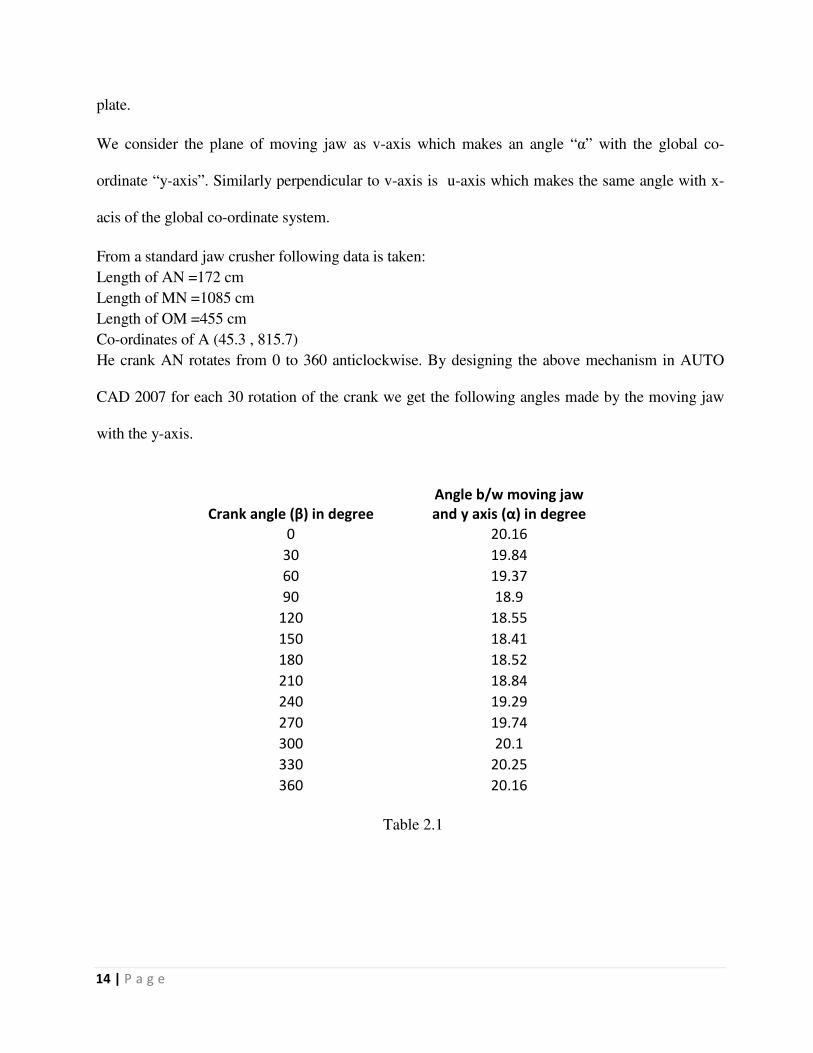
We consider the plane of moving jaw as v-axis which makes an angle “α” with the global co-
ordinate “y-axis”. Similarly perpendicular to v-axis is u-axis which makes the same angle with x-
acis of the global co-ordinate system.
From a standard jaw crusher following data is taken:
Length of AN =172 cm
Length of MN =1085 cm
Length of OM =455 cm
Co-ordinates of A (45.3 , 815.7)
He crank AN rotates from 0 to 360 anticlockwise. By designing the above mechanism in AUTO
CAD 2007 for each 30 rotation of the crank we get the following angles made by the moving jaw
with the y-axis.
Table 2.1
Crank angle (β) in degree
Angle b/w moving jaw
and y axis (α) in degree
0 20.16
30 19.84
60 19.37
90 18.9
120 18.55
150 18.41
180 18.52
210 18.84
240 19.29
270 19.74
300 20.1
330 20.25
360 20.16
Page 23
15 | P a g e
Figure 2.2
The graph shown above is crank angle v/s α (angle between moving jaw and global y axis). The
crank angle in x axis is taken 300 as 1 unit.
Interpretation of the graph:
The graph shows as the moving jaw approaches its counterpart which is stationary it tends to be
vertical, i.e. the angle between y axis and the moving jaw decreases. As a result the crushed product
slips downwards.
Page 24
16 | P a g e
2.3 Derivation for Displacement of any point on the moving jaw plane:
We consider any point P (u,v) on the swinging jaw, On the moving jaw plate u= 0. The coordinates
p (u,v) can be represented in global axis in terms of x and y as below.
x = u Cos α+ (l - v) Sin α + a - r sin β
y = u Sin α+ (l - v) Cos α + b - r cos β
We take 11 sample points on the moving jaw plate at u=0 and v=85, 185, 285,
385, 485,585, 685, 785, 885. 985,1085 to study the kinematic behavior based on
geometry.
A matlab program is written to find out the position os the above mentioned ponts
and the following graphs are plotted from the output data.
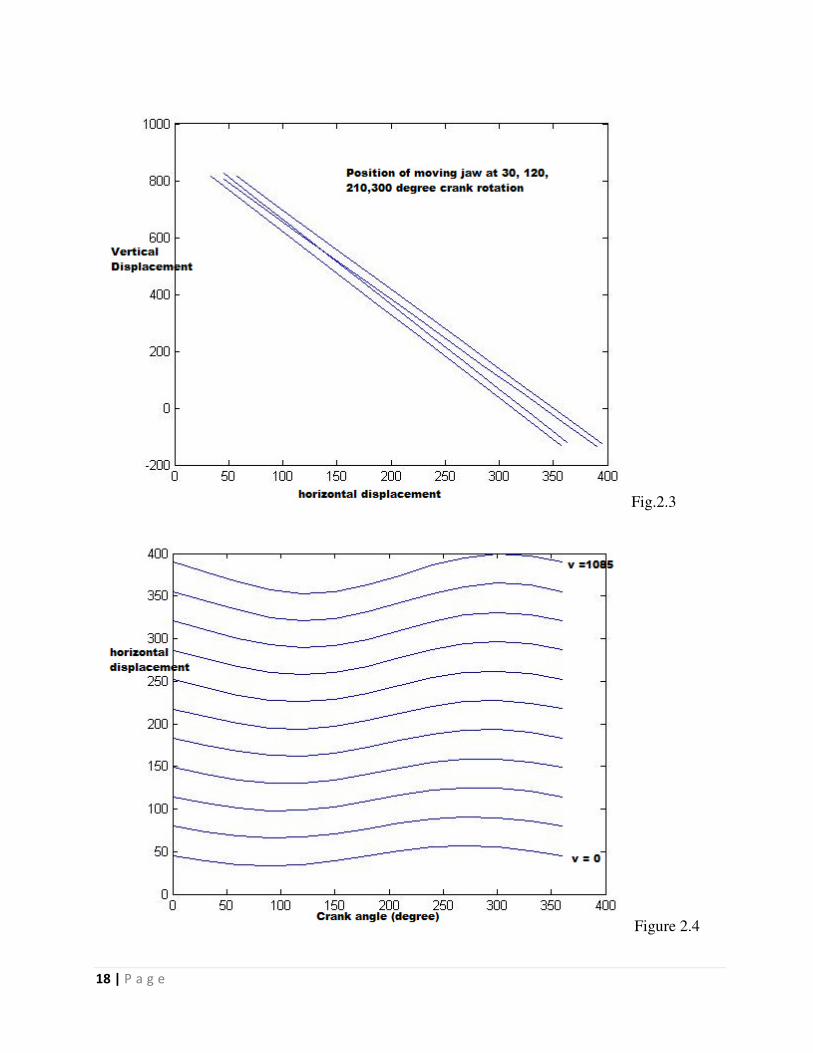
1. Position of movable plate at different crank angle
2. Horizontal displacement of all 11 points v/s crank angle
3. Horizontal displacement and vertical displacement V/s crank angle for the
5th
point.
4. The physical positions of the 5th point i.e. its vertical v/s horizonta
displacement.
2.3.1 Matlab program to find out displacement.
clc
clear
n=1;
l=1085;
a=45.3;
r=12;
u=0;
Page 25
17 | P a g e
b=815.7;
i=1;
theta=[20.16 19.84 19.37 18.90 18.55 18.41 18.52 18.84 19.29 19.74 20.10 20.25 20.16];
for psi=0:30:360
n=1;
for v=85:100:1085
x(i,n)=u*cos(theta(i)*pi/180)+(l-v)*sin(theta(i)*pi/180)+a-r*sin(psi*pi/180);
y(i,n)=u*sin(theta(i)*pi/180)-(l-v)*cos(theta(i)*pi/180)+b-r*cos(psi*pi/180);
n=n+1;
end
i=i+1;
end
psinew=0:30:360;
figure(1)
plot(x(1,:),y(1,:));
hold on
plot(x(4,:),y(4,:));
hold on
plot(x(7,:),y(7,:));
hold on
plot(x(10,:),y(10,:));
figure(2)
for i=1:1:11
plot(psinew,x(:,i))
hold on
end
figure(3)
plot(psinew,y(:,5))
hold on
plot(psinew,x(:,5))
figure(4)
plot(y(:,5),x(:,5))
x;
y;
Page 26
18 | P a g e
Fig.2.3
Figure 2.4
Page 27
19 | P a g e
Figure2.5
Figure 2.6
Page 28
20 | P a g e
2.3.2 Interpretation of the graphs:
1. Every point on the moving jaw follows an elliptical path
2. When the moves towards the fixed jaw; it goes vertically down and in
the return stroke it moves vertically up.
2.4 Derivation for Displacement of any point on the moving jaw plane:
By differentiating the position we get the equation to calculate the horizontal
and vertical velocities. Expressions for horizontal and vertical velocities are
given below:
Vx= (l - v) Cos α ( dα / dβ) - r cos β - u Sin α ( dα/dβ)
Vy = (l - v) Sin α ( dα / dβ) + r Sin β + u Cos α ( dα / dβ)
A matlab program is written to find out the velocities of the mentioned points and
the following graphs are plotted from the output data.
1. Horizontal velocity of all 11 points v/s crank angle
2. Vertical velocity of all 11 points v/s crank angle
3. Velocity V/s crank angle for all 11 points
2.4.1 Matlab program to calculate and plot horizontal & vertical velocities.
clc
clear
n=1;
l=1085;
a=45.3;
r=12;
u=0;
Page 29
21 | P a g e
b=815.7;
i=1;
theta=[20.16 19.84 19.37 18.90 18.55 18.41 18.52 18.84 19.29 19.74 20.10
20.25 20.16];
psi(1)=0;
m=0;
for i=1:1:13
n=1;
for v=85:100:1085
vx(i ,n)=(l-v)*cos(theta(i)*pi/180)*m-r*cos(psi(i)*pi/180)-
u*sin(theta(i)*pi/180)*m;
vy(i ,n)=(l-
v)*sin(theta(i)*pi/180)*m+r*sin(psi(i)*pi/180)+u*cos(theta(i)*pi/180)*m;
n=n+1;
end
if(i<=12)
psi(i+1)=psi(i)+30;
m=(theta(i+1)-theta(i))/(psi(i+1)-psi(i));
end
end
figure(1)
for i=1:1:11
plot(psi,vx(: ,i));
hold on;
end
figure(2)
for i=1:1:11
plot(psi,vy(: ,i));
hold on;
end
for i=1:1:13
for j=1:1:11
v(i,j)=sqrt(vx(i,j)^2+vy(i,j)^2);
end
end
figure(3)
for i=1:1:11
plot(psi,v(:, i))
hold on;
end
Page 30
22 | P a g e
Figure2.7
Figure 2.8
Page 31
23 | P a g e
Figure 2.9
2.4.2 Interpretation of the graphs:
1. The rate of change of vertical velocity is more for the top most point and
decreases downwards.
2. The rate of change of horizontal velocity is more for the bottom most
point and decreases upwards.
3. The maximum rate of change of final velocity is more for the points
away from the crank.
Page 32
24 | P a g e
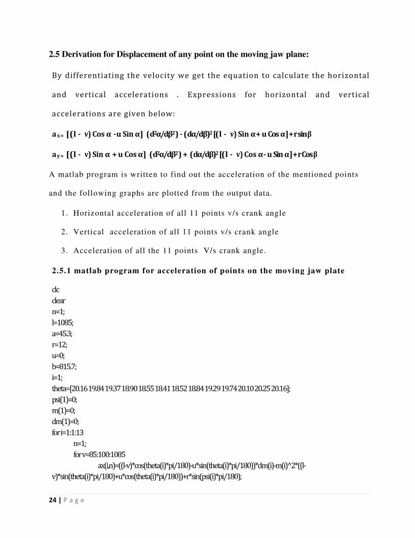
2.5 Derivation for Displacement of any point on the moving jaw plane:
By differentiating the velocity we get the equation to calculate the horizontal
and vertical accelerations . Expressions for horizontal and vertical
accelerations are given below:
ax= [(l - v) Cos α - u Sin α ] ( d2α/dβ2 ) - ( dα/dβ)2 [(l - v) Sin α + u Cos α ] + r sin β
ay = [(l - v) Sin α + u Cos α ] ( d2α/dβ2 ) + ( dα/dβ)2 [(l - v) Cos α - u Sin α ] + r Cos β
A matlab program is written to find out the acceleration of the mentioned points
and the following graphs are plotted from the output data.
1. Horizontal acceleration of all 11 points v/s crank angle
2. Vertical acceleration of all 11 points v/s crank angle
3. Acceleration of all the 11 points V/s crank angle.
2.5.1 matlab program for acceleration of points on the moving jaw plate
clc
clear
n=1;
l=1085;
a=45.3;
r=12;
u=0;
b=815.7;
i=1;
theta=[20.16 19.84 19.37 18.90 18.55 18.41 18.52 18.84 19.29 19.74 20.10 20.25 20.16];
psi(1)=0;
m(1)=0;
dm(1)=0;
for i=1:1:13
n=1;
for v=85:100:1085
ax(i,n)=((l-v)*cos(theta(i)*pi/180)-u*sin(theta(i)*pi/180))*dm(i)-m(i)̂ 2*((l-
v)*sin(theta(i)*pi/180)+u*cos(theta(i)*pi/180))+r*sin(psi(i)*pi/180);
Page 33
25 | P a g e
ay(i,n)=((l-v)*cos(theta(i)*pi/180)-u*sin(theta(i)*pi/180))*m(i)̂ 2+((l-
v)*sin(theta(i))*pi/180+u*cos(theta(i)*pi/180))*dm(i)+r*cos(psi(i)*pi/180);
n=n+1;
end
if(i<=12)
psi(i+1)=psi(i)+30;
m(i+1)=(theta(i+1)-theta(i))/(psi(i+1)-psi(i));
dm(i+1)=(m(i+1)+m(i))/(psi(i+1)-psi(i));
end
end
figure(1)
for i=1:1:11
plot(psi,ax(:,i));
hold on;
end
figure(2)
for i=1:1:11
plot(psi,ay(:,i));
hold on;
end
for i=1:1:13
for j=1:1:11
a(i,j)=sqrt(ax(i,j)̂ 2+ay(i,j)̂ 2);
end
end
figure(3)
for i=1:1:11
plot(psi,a(:,i))
hold on;
end
Page 34
26 | P a g e
Figure
2.10 Figure
Page 35
27 | P a g e
2.11
Figure 2.12
2.5.2 Interpretation of the graphs:
1. With progress from 0 to 360 degree crank rotation the horizontal
acceleration first increases and then decreases.
2. With progress from 0 to 360 degree crank rotation the vertical
acceleration first decrease and then increases .
3. The maximum acceleration is observed for the points farthest away
from the crank.
Page 36
28 | P a g e
Chapter: 3
Effects of sliding motion on jaw plate wear
3.1 Breakage Analysis:
Under compression as the energy intensity increases, there are three types of fracture
mechanisms are observed as is illustrated in figure 3.1. The particle fracture mechanism
in jaw crusher chamber is the mixture of the cleavage and the abrasion [7]. The abrasion
fracture is caused with the localized too much energy input to the area directly under the
loading points and the friction between the jaw plates and the particle. The induced tensile
stress results in the cleavage fracture. The breakage process due to the point contact loading
that occurs between the plates of a jaw crusher and a particle is shown in figure 3.2
---------------------------->
Increasing energy intensity
Particle fracture mechanism [7]. Figure 3
Figure 3.2, fracture caused by compression crushing [7].
Page 37
29 | P a g e
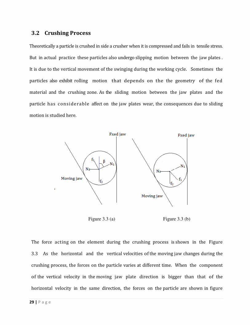
3.2 Crushing Process
Theoretically a particle is crushed in side a crusher when it is compressed and fails in tensile stress.
But in actual practice these particles also undergo slipping motion between the jaw plates .
It is due to the vertical movement of the swinging during the working cycle. Sometimes the
particles also exhibit rolling motion that depends on the the geometry of the fed
material and the crushing zone. As the sliding motion between the jaw plates and the
particle has considerable affect on the jaw plates wear, the consequences due to sliding
motion is studied here.
Figure 3.3 (a) Figure 3.3 (b)
The force acting on the element during the crushing process is shown in the Figure
3.3 As the horizontal and the vertical velocities of the moving jaw changes during the
crushing process, the forces on the particle varies at different time. When the component
of the vertical velocity in the moving jaw plate direction is bigger than that of the
horizontal velocity in the same direction, the forces on the particle are shown in figure
Page 38
30 | P a g e
3.3(a). When the component of the vertical velocity in the jaw plate direction is smaller
than that of the horizon velocity, the forces on the particle are shown in figure 3.3(b). The
magnitude of gravitational force is much smaller than others, it can be ignored.
Resolving forces in horizontal direction for figure 3.3(a)
for equilibrium N1 Sin β – f1 Cos β – N2 = 0 ( Equation 3.1 )
Resolving forces in vertical direction for figure 3.3(a
for equilibrium N1 Cos β + f1 Sin β – f2 = 0 ( Equation 3.2 )
Let us assume slide takes place between the particle and the swinging jaw plate.
Coefficient of friction is taken as µ1 between moving jaw and particle and µ2 between fixed
jaw and the particle under compression.
µ2 = ( Cos β + µ1 Sin β ) / (Sin β – µ1 Cos β) > 0 ( Equation 3.3 )
µ1 - µ2 = - {(µ1)2 Cos β – Cos β }/ (Sin β - µ1 Cos β) ( Equation 3.4 )
It is inconsistent to the assumption.
Now, Let us consider slide takes place between the particle and the fixed jaw plate.
f2 = µ1 N2
and µ2 = (µ1 Sin β + Cos β ) / (Sin β + µ1 Cos β) ( Equation 3.5 )
µ1 - µ2 = - {(µ1)2 Cos β + Cos β }/ (Sin β + µ1 Cos β) > 0 ( Equation 3.6 )
Which is rational.
Hence from the above analysis for figure 3.3(b) it is proved that condition for the particle to slip
against the fixed jaw plate is much easier than with the moving jaw plate. Under figure 3.3(b)
condition the slide between the particle and the fixed plate is also unavoidable. So in
either case the chance of the particle to slide with the fixed jaw is more as compared to
Page 39
31 | P a g e
the moving jaw. In fact, due to the vertical motion and the irregular geometry of particles, a
classification process before the particle fracture may exist during close process, in which
the particle position adjustment takes place.
3.3 Wear analysis
Squeezing and sliding are the two principal factors affecting the jaw plates wear . High
manganese steel are widely used as the liner for moving jaw as it possesses excellent work
hardening character. By scanning the worn jaw plates under the electron microscope, it is
found that the sliding is the main factor to the jaw plates wear and the sufficient
squeezing can even relieve the jaw plate wear [1]. Squeezing plays the main role at the top
of the jaw crusher as the sliding is small at this area , the wear in this zone is small. As we
move down the crusher, the probability to slip increases and the wear becomes more serious.
While moving along the length , at the middle lower part of the crusher, the ratio of the
vertical distance to the horizontal stroke reaches the maximal value resulting maximum
wear in this region. Very few particles come in contact with the edge parts, so the ware at
the lower parts is considerably small. For the same jaw crusher, the slide between
the particle and the moving jaw plate, is more compared to the moving jaw plate wand hence
the wear is dominant in fixed jaw relative to its stationary counterpart.
Page 40
32 | P a g e
Chapter: 4
Design Of Flywheel
4.1 Flywheel
A flywheel is used as a reservoir of energy in machines. It stores the excess of energy when the
supply is more than the requirement and utilizes the same when the rate of supply of energy
falls. Basically it is used as a storage device for rotational energy. Flywheels helps to stabilize
the rotation of the shaft when a varying torque is exerted on it by its power source; by resisting
changes in their rotational speed. Flywheels can be used to produce very high power pulses for
experiments, where drawing the power from the public network would produce unacceptable
spikes.
4.2 Role of Flywheel in Jaw crusher
From the study of kinematic behavior of jaw crushers it has been found that for one complete
rotation of the crank the forces developed on the moving jaw plate varies. At some region this
force is sufficiently large to crush the material and in some zone this force could produce a stress
less than the ultimate stress of the fed material. Hence to get the fed crushed in a regular time
the energy lost during over supply should be utilized when the supply value falls below the
requirement mark. To produce this effect every jaw crusher is equipped with a heavy flywheel
with significant moment of inertia.
Page 41
33 | P a g e
Figure 4.1
Energy stored in a flywheel:
Let m = mass of the flywheel in Kg
K= radius of gyration of the flywheel
I= mass moment of inertia of the flywheel
ω1 and ω2= maximum and minimum angular speed during the cycle in rpm
ω = mean angular speed during the cycle in radian
Cs= coefficient of fluctuation of speed = (ω1-ω2)/ ω
Maximum fluctuation of energy = maximum KE – Minimum KE
= ½ I( ω1)2 – ½ I (ω2)2 = Iω2 Cs = 2 E Cs
Page 42
34 | P a g e
4.3 Stresses in a flywheel:
Assuming the rim is unstrained by the arms, the tensile stress in the rims due to centrifugal
force is determined as a thin cylinder subjected to internal pressure.
Let w = Width of the rim
d = thickness of the rim
A= area of X-section of the rim = w x d
D= mean diameter of the flywheel
R= mean radius of the flywheel
ρ= density of the flywheel
ω= angular speed of the flywheel
µ= linear velocity of the flywheel
σt= tensile or hoop stress
Figure 4.2
Page 43
35 | P a g e
Considering a small element of the rim as shown in Figure 4.2; Let it makes an angle dα at the
centre of the flywheel.
Volume of this small element = A.R. dα
Mass of the element = volume x density = A.R. dα ρ
Centrifugal force on this element = dF= dm. ω2. R = ρ A.R2. ω2. dα
Vertical component of dF = dF Sin α = ρ A.R2. ω2. dα Sin α
Total vertical force across the rim diameter X-Y= ρ A.R2. ω2. ∫ Sin α dα = 2 ρ A.R
2. ω2.
This vertical force is restricted by a force 2P such that
2P = 2σt x A = 2 ρ A.R2. ω2.
σt = ρ R2. ω2 = ρ µ2
4.3.1 Tensile bending stress in the rim due to restrain of the arms
Assumption: Each portion of the rim between a pair of arms behaves like a beam fixed at
both ends and uniformly loaded.
Say, Length between fixed ends = π D/ n = 2 π R/n
The uniformly distributed load k per meter length shall be equal to the centrifugal force
between pair of arms,
k= w .d. ρ R. ω2
The maximum bending moment , M = k l2 /12= w .d. ρ R. ω2 (2 π R/n )2 / 12
Section modulus , Z = w d2 / 6
Bending stress, σb = M/ Z = 6. w .d. ρ R. ω2 (2 π R/n )2 / 12 w d
2
= 19.74 ρ µ2 R/ n
2 t
Total stress on the rim σ = σt + σb
Page 44
36 | P a g e
4.3.2 Torque v/s Crank angle graph
Figure 4.3
4.3.3 The following matlab program finds out the value of toque at different crank angles.
clc
clear
n=1;
l=1085;
a=45.3;
r=12;
u=0;
b=815.7;
i=1;
theta=[20.16 19.84 19.37 18.90 18.55 18.41 18.52 18.84 19.29 19.74 20.10 20.25 20.16];
psi(1)=0;
m(1)=0;
dm(1)=0;
for i=1:1:13
n=1;
for v=85:100:1085
Page 45
37 | P a g e
ax(i,n)=((l-v)*cos(theta(i)*pi/180)-u*sin(theta(i)*pi/180))*dm(i)-m(i)̂ 2*((l-
v)*sin(theta(i)*pi/180)+u*cos(theta(i)*pi/180))+r*sin(psi(i)*pi/180);
ay(i,n)=((l-v)*cos(theta(i)*pi/180)-u*sin(theta(i)*pi/180))*m(i)̂ 2+((l-
v)*sin(theta(i))*pi/180+u*cos(theta(i)*pi/180))*dm(i)+r*cos(psi(i)*pi/180);
n=n+1;
end
if(i<=12)
psi(i+1)=psi(i)+30;
m(i+1)=(theta(i+1)-theta(i))/(psi(i+1)-psi(i));
dm(i+1)=(m(i+1)+m(i))/(psi(i+1)-psi(i));
end
end
figure(1)
for i=1:1:11
plot(psi,ax(:,i));
hold on;
end
figure(2)
for i=1:1:11
plot(psi,ay(:,i));
hold on;
end
for i=1:1:13
for j=1:1:11
a(i,j)=sqrt(ax(i,j)̂ 2+ay(i,j)̂ 2);
end
end
figure(3)
for i=1:1:11
plot(psi,a(:,i))
hold on;
a(:,1)
mean(a(:,1))
figure(4)
plot(psi,a(:,1))
holdon;
plot(psi,11.46)
end
Page 46
38 | P a g e
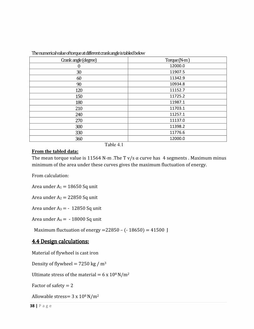
The numerical value of torque at different crank angle is tabled below
Crank angle (degree) Torque (N-m )
0 12000.0
30 11907.5
60 11342.9
90 10934.8
120 11152.7
150 11725.2
180 11987.1
210 11703.1
240 11257.1
270 11137.0
300 11398.2
330 11776.6
360 12000.0
Table 4.1
From the tabled data:
The mean torque value is 11564 N-m .The T v/s α curve has 4 segments . Maximum minus minimum of the area under these curves gives the maximum fluctuation of energy.
From calculation:
Area under A1 = 18650 Sq unit
Area under A2 = 22850 Sq unit
Area under A3 = - 12850 Sq unit
Area under A4 = - 18000 Sq unit
Maximum fluctuation of energy =22850 – (- 18650) = 41500 J
4.4 4.4 4.4 4.4 Design calculations:Design calculations:Design calculations:Design calculations:
Material of flywheel is cast iron
Density of flywheel = 7250 kg / m3
Ultimate stress of the material = 6 x 10⁸ N/m2
Factor of safety = 2
Allowable stress= 3 x 10⁸ N/m2
Page 47
39 | P a g e
The mean angular velocity of the flywheel = 300 rpm = 200 x 2π / 60 = 31.42 rad/s
Assuming fluctuation of speed is 20% of the mean speed;
ω1 – ω2= .2 ω
Coefficient of fluctuation of energy = Cs =( ω1 – ω2) / ω = .2
But, ΔE = I ω2 Cs
I= ΔE / ω2 Cs = 41500/ (31.42)2 x .2 = 210.2 Kg m2
From basic design ,
w = breadth of the flywheel rim = 2 d = 2 x (thickness of flywheel rim)
Induced tensile stress, = σt = ρ µ2
µ = √ (3 x 10
8 / 7250 ) = 20.34 m/s
Peripheral velocity, µ = π D N / 60
D = (28.76 x 60) / (π x 300) = 1.295 m
Total energy stored in fly wheel, E = ΔE/ 2 CS = 41500/ 2 x 0.2 = 103750 Nm
Energy of the fly wheel rim, E rim = 0.92 E = 95450 Nm
But, E rim= ½ m µ2
m= 2 E rim/ µ2 = 2 x 95450 / (20.34)
2 = 461.42 Kg
also ; m = w .d . πD. ρ = 2 d2 πD. ρ
d= √ ( m / 2 πD. ρ ) = 78.22 mm
w = 2 x d = 156.4 mm
Page 48
40 | P a g e
4.5 Spring Design.
From experiment it is found that the energy required for breaking 1 ton Dehbeed Granite is 1696
Joule. Considering the jaw crusher under study is used to crush 1 ton such material per hour.
Power = Force X velocity
FMAX= P/ Vmin = 1696 x 1000 / (1.22 x 3600) = 386.15 N
Figure 4.4
W= load on the spring = T Cos 350 = 386.15
T = 470. 63 N
Maximum Spring deflection:
One end of the tension bar is attached to moving jaw and the other one is fixed with the column,
Length of the tension rod = 1000 mm
Coordinate of the fixed end of the tension bar in global coordinate system = (-576.3 , 33.8)
Coordinate of the moving end (farthest point) = (428.72 , -219.66)
Distance between farthest point and fixed end = 1036.88 mm
Maximum deflection of spring = 36.88 mm
Spring material = carbon steel
Spring diameter, d= 12 mm
Page 49
41 | P a g e
Ultimate stress = 294 MPa
Modulus of Rigidity = G = 80 KPa
Young’s Modulus = E= 210 KPa
D/d = 10
Mean diameter, D = 120 mm
σ1 = 8 W D / (πd3) = 83.22 MPa
σ2 = 4 W / (πd2) = 4.1 MPa
σ = σ1 + σ2 = 87.38 MPa
Factor of Safety = 294 / 87.38 = 3.35
4.5 Final results4.5 Final results4.5 Final results4.5 Final results
Material of flywheel is cast iron Density of flywheel = 7250 kg / m3
Ultimate stress of the material = 6 x 10⁸ N/m2
Allowable stress = 3 x 10⁸ N/m2
Mass of fly wheel = 461.42 Kg Diameter of flywheel = 1.295 m Thickness of rim of the flywheel = 78.22 mm Width of rim of the flywheel = 156.4 mm
Table 4.2
Page 50
42 | P a g e
References:
1. CAO Jinxi, RONG Xingfu, YANG Shichun, jaw plate kinematical analysis for
single toggle jaw crusher design, IEEE International Technology and Innovation
Conference, 62-66, 2006
2. .Bharule Ajay Suresh, Computer aided design and Analysis of Swing Jaw Plate of
Jaw Crusher, NIT Rourkela, 1-11, 2009
3. R.S. Khurmi & J.K. Gupta, Text book of Machine Design, 788-790, 2005 edition.
4. Gupta Ashok, Yan D.S. “Mineral Processing Design and Operation-An
introduction”, Published by Elsevier, 2006, Pages 99-127
5. http://www.sbmchina.com/jaw crusher/working principle/structure characteristics
6. http://www.westpromachinery.com/jaw crusher/components/jaw plates
7. James G Donovan. Fracture toughness based models for the prediction ofpower consumption, product size and capacity of jaw crusher, Ph.D. thesis, U.S.A, Virginia Polytechnic Institute and state University, 2003.
8. http://en.wikipedia.org/wiki/Flywheel
9. http://www.conquip.us/images/jaw-diagram-600.jpg
10. http://www.aggdesigns.com/Jaw-Crusher-info.htm
.