27
1 FAMU-FSU College of Engineering Computer Architecture EEL 4713/5764, Spring 2006 Dr. Michael Frank Module #6 – MIPS ISA, part 1: Instructions and Addressing
| Date post: | 01-Jan-2016 |
| Category: |
Documents |
| Upload: | velma-cardenas |
| View: | 21 times |
| Download: | 1 times |

1
FAMU-FSU College of Engineering
ComputerArchitectureEEL 4713/5764, Spring 2006
Dr. Michael Frank
Module #6 – MIPS ISA, part 1:Instructions and Addressing

2
Course Instructional Objectives #2&3 As the syllabus says:
At the completion of this course, students should be able to…CIO #2 (ao). (AsmML) Derive machine code from assembly instructions.CIO #3 (aco). (CAsm) Derive assembler code from an equivalent C code representation
These CIOs relate to following Program Outcomes: Students graduating from the BSEE and BSCpE degree programs will have:
PO (a). (Apply) An ability to apply knowledge of mathematics, science and engineering;PO (c). (Design) An ability to design a system, component, or process to meet desired needs;PO (o). (Topics) EE: A knowledge of electrical engineering applications selected from the …digital
systems… areas; CpE: A knowledge of computer science and computer engineering topics including …computer architecture.
Under “assessment instruments,” the syllabus says:2. AsmML (a) Apply-3, (o) Topics-3 Students will solve exam problems in which they must hand-assemble MIPS (or similar)
assembly language instructions to their binary machine-language representations.3. CAsm (a) Apply-3, (c) Design-3, (o) Topics-3 Students will solve exam problems in which they must hand-compile short C language code
fragments to equivalent assembly language code for a MIPS or similar instruction-set architecture.
3
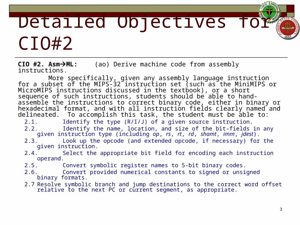
Detailed Objectives for CIO#2CIO #2. AsmML: (ao) Derive machine code from assembly instructions. More specifically, given any assembly language instruction for a subset of the MIPS-32 instruction set (such as the MiniMIPS or MicroMIPS instructions discussed in the textbook), or a short sequence of such instructions, students should be able to hand-assemble the instructions to correct binary code, either in binary or hexadecimal format, and with all instruction fields clearly named and delineated. To accomplish this task, the student must be able to:
2.1. Identify the type (R/I/J) of a given source instruction.2.2. Identify the name, location, and size of the bit-fields in any given instruction type
(including op, rs, rt, rd, shamt, imm, jdest).2.3. Look up the opcode (and extended opcode, if necessary) for the given instruction.2.4. Select the appropriate bit field for encoding each instruction operand.2.5. Convert symbolic register names to 5-bit binary codes.2.6. Convert provided numerical constants to signed or unsigned binary formats.2.7 Resolve symbolic branch and jump destinations to the correct word offset relative to the
next PC or current segment, as appropriate.
4
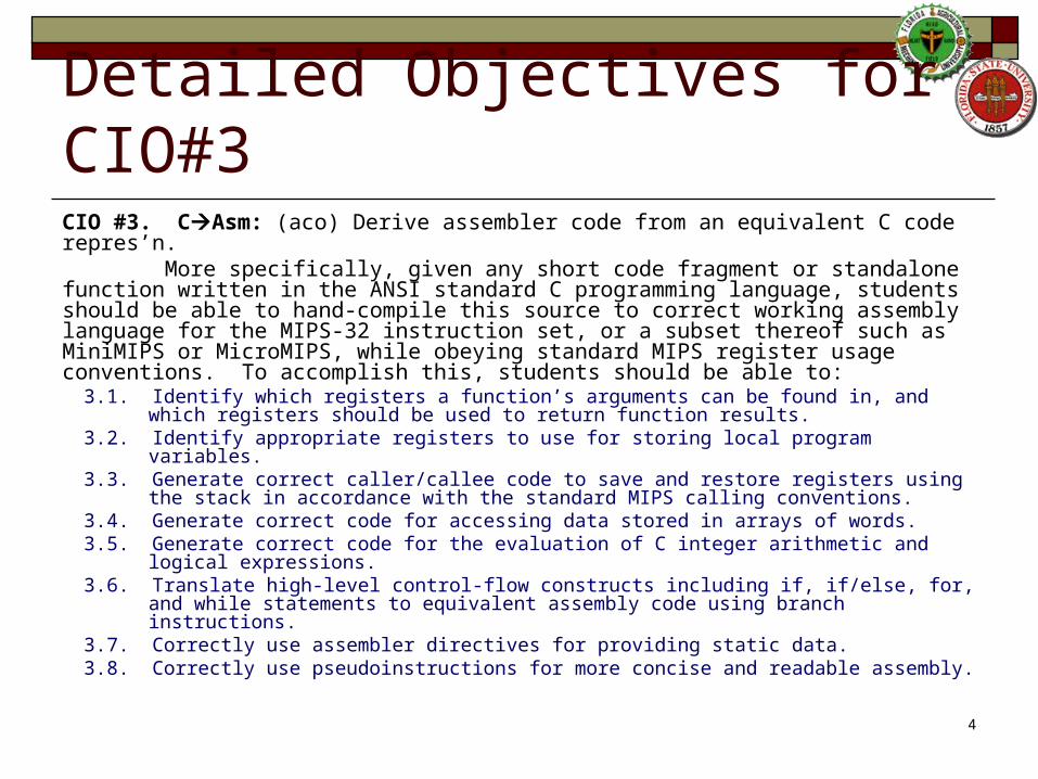
Detailed Objectives for CIO#3CIO #3. CAsm: (aco) Derive assembler code from an equivalent C code repres’n. More specifically, given any short code fragment or standalone function written in the ANSI standard C programming language, students should be able to hand-compile this source to correct working assembly language for the MIPS-32 instruction set, or a subset thereof such as MiniMIPS or MicroMIPS, while obeying standard MIPS register usage conventions. To accomplish this, students should be able to:
3.1. Identify which registers a function’s arguments can be found in, and which registers should be used to return function results.
3.2. Identify appropriate registers to use for storing local program variables.3.3. Generate correct caller/callee code to save and restore registers using the stack in
accordance with the standard MIPS calling conventions.3.4. Generate correct code for accessing data stored in arrays of words.3.5. Generate correct code for the evaluation of C integer arithmetic and logical expressions.3.6. Translate high-level control-flow constructs including if, if/else, for, and while statements
to equivalent assembly code using branch instructions.3.7. Correctly use assembler directives for providing static data.3.8. Correctly use pseudoinstructions for more concise and readable assembly.
June 2005 Computer Architecture, Instruction-Set Architecture Slide 5
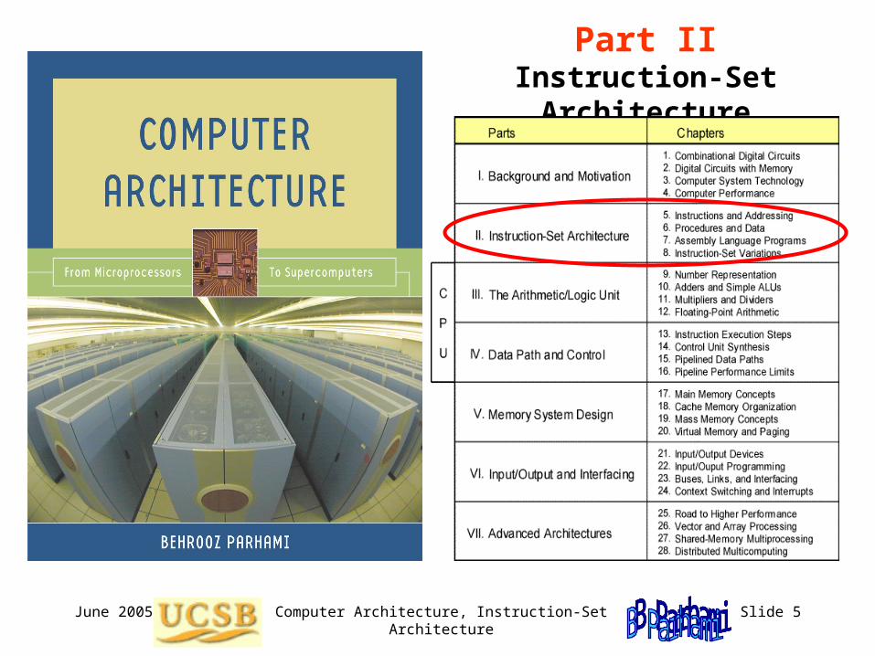
Part IIInstruction-Set
Architecture
June 2005 Computer Architecture, Instruction-Set Architecture Slide 6
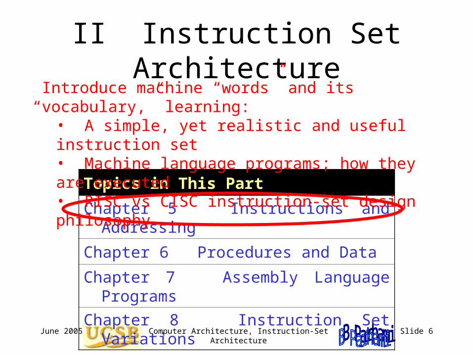
II Instruction Set Architecture
Topics in This Part
Chapter 5 Instructions and Addressing
Chapter 6 Procedures and Data
Chapter 7 Assembly Language Programs
Chapter 8 Instruction Set Variations
Introduce machine “words” and its “vocabulary,” learning:• A simple, yet realistic and useful instruction set• Machine language programs; how they are executed• RISC vs CISC instruction-set design philosophy

June 2005 Computer Architecture, Instruction-Set Architecture Slide 7
5 Instructions and Addressing
Topics in This Chapter
5.1 Abstract View of Hardware
5.2 Instruction Formats
5.3 Simple Arithmetic / Logic Instructions
5.4 Load and Store Instructions
5.5 Jump and Branch Instructions
5.6 Addressing Modes
First of two chapters on the instruction set of MiniMIPS:• Required for hardware concepts in later chapters• Not aiming for proficiency in assembler programming

June 2005 Computer Architecture, Instruction-Set Architecture Slide 8
5.1 Abstract View of Hardware
Figure 5.1 Memory and processing subsystems for MiniMIPS.
Memory up to 2 words 30
Loc 0 Loc 4 Loc 8
Loc m 4
Loc m 8
4 B / location
m 2 32
$0
$1
$2
$31
Hi Lo
ALU
$0
$1
$2
$31 FP
arith
EPC
Cause
BadVaddr Status
EIU FPU
TMU
Execution & integer unit
Floating- point unit
Trap & memory unit
. . .
. . .
(Coproc. 1)
(Coproc. 0)
(Main proc.)
Integer mul/div
Chapter 10
Chapter 11
Chapter 12 Exception PC

PCSpim appearance

June 2005 Computer Architecture, Instruction-Set Architecture Slide 10
Data Types
MiniMIPS registers hold 32-bit (4-byte) words. Other common data sizes include byte, halfword, and doubleword.
Byte
Halfword
Word
Doubleword
Halfword = 2 bytes
Byte = 8 bits
Word = 4 bytes
Doubleword = 8 bytes

June 2005 Computer Architecture, Instruction-Set Architecture Slide 11
Register Conventions
Figure 5.2 Registers and data sizes in MiniMIPS.
Temporary values
More temporaries
Operands
Global pointer Stack pointer Frame pointer Return address
Saved
Saved Procedure arguments
Saved across
procedure calls
Procedure results
Reserved for assembler use
Reserved for OS (kernel)
$0 $1 $2 $3 $4 $5 $6 $7 $8 $9 $10 $11 $12 $13 $14 $15 $16 $17 $18 $19 $20 $21 $22 $23 $24 $25 $26 $27 $28 $29 $30 $31
0
$zero
$t0
$t2
$t4
$t6
$t1
$t3
$t5
$t7 $s0
$s2
$s4
$s6
$s1
$s3
$s5
$s7 $t8 $t9
$gp $sp $fp $ra
$at
$k0 $k1
$v0
$a0
$a2
$v1
$a1
$a3
A doubleword sits in consecutive registers or memory locations according to the big-endian order (most significant word comes first)
When loading a byte into a register, it goes in the low end Byte
Word
Doublew ord
Byte numbering: 0 1 2 3
3
2
1
0
A 4-byte word sits in consecutive memory addresses according to the big-endian order (most significant byte has the lowest address)
But in SPIM, theendian-ness depends on theunderlying HW
June 2005 Computer Architecture, Instruction-Set Architecture Slide 12
5.2 Instruction Formats
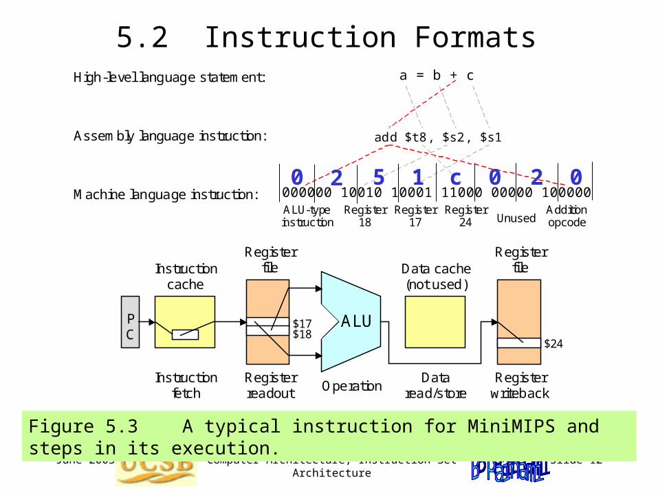
Figure 5.3 A typical instruction for MiniMIPS and steps in its execution.
Assembly language instruction:
Machine language instruction:
High-level language statement:
000000 10010 10001 11000 00000 100000
add $t8, $s2, $s1
a = b + c
ALU-type instruction
Register 18
Register 17
Register 24 Unused
Addition opcode
ALU
Instruction fetch
Register readout
Operation
Data read/store
Register writeback
Register file
Instruction
cache
Data cache (not used)
Register file
P C
$17 $18
$24
0 2 5 1 c 0 2 0

June 2005 Computer Architecture, Instruction-Set Architecture Slide 13
Add, Subtract, and Specification of Constants
MiniMIPS add & subtract instructions; e.g., compute: g = (b + c) (e + f)
add $t8,$s2,$s3 # put the sum b + c in $t8 add $t9,$s5,$s6 # put the sum e + f in $t9 sub $s7,$t8,$t9 # set g to ($t8) ($t9)
Decimal and hex constants
Decimal 25, 123456, 2873 Hexadecimal 0x59, 0x12b4c6, 0xffff0000
Machine instruction typically contains
an opcode one or more source operands possibly a destination operand

June 2005 Computer Architecture, Instruction-Set Architecture Slide 14
MiniMIPS Instruction Formats
Figure 5.4 MiniMIPS instructions come in only three formats: register (R), immediate (I), and jump (J).
5 bits 5 bits
31 25 20 15 0
Opcode Source register 1
Source register 2
op rs rt
R 6 bits 5 bits
rd
5 bits
sh
6 bits
10 5 fn
Destination register
Shift amount
Opcode extension
Immediate operand or address offset
31 25 20 15 0
Opcode Destination or data
Source or base
op rs rt operand / offset
I 5 bits 6 bits 16 bits 5 bits
0 0 0 0 0 0 0 0 0 0 0 1 1 1 1 1 1 0 0 0 0 0 0 0 0 0
31 0
Opcode
op jump target address
J Memory word address (byte address divided by 4)
26 bits
25
6 bits
June 2005 Computer Architecture, Instruction-Set Architecture Slide 15
5.3 Simple Arithmetic/Logic Instructions
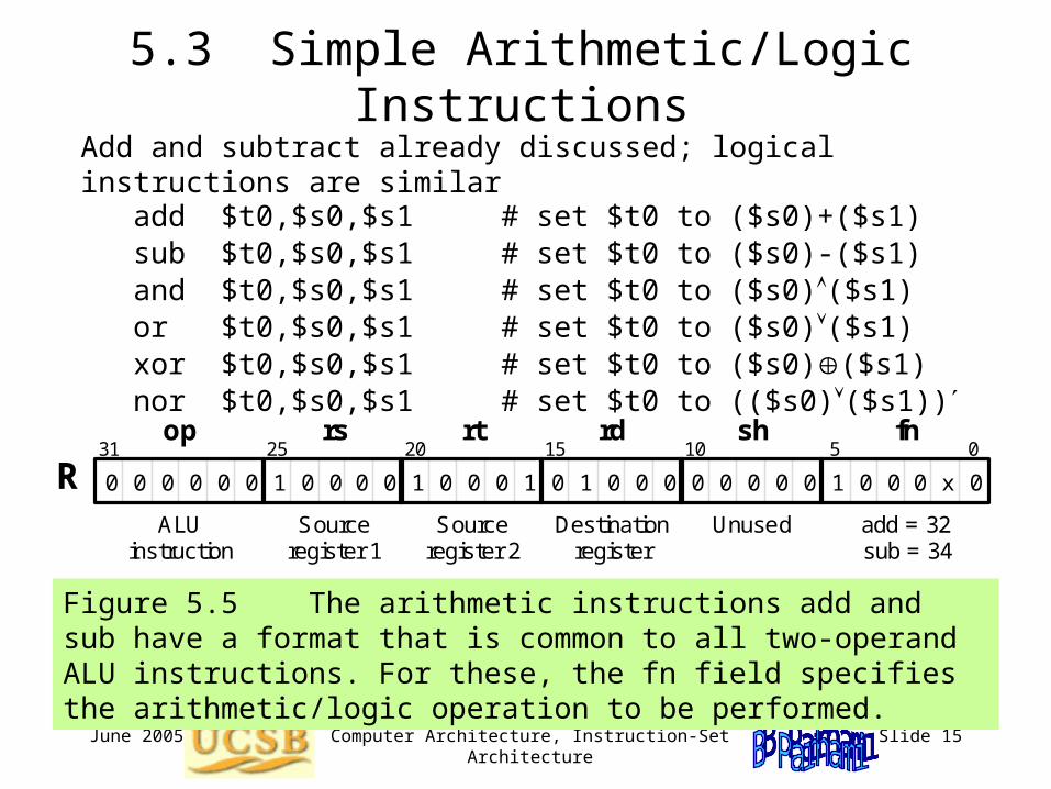
Figure 5.5 The arithmetic instructions add and sub have a format that is common to all two-operand ALU instructions. For these, the fn field specifies the arithmetic/logic operation to be performed.
0 0 0 0 0 0 0 0 0 0 0 0 0 0 0 1 x 0 0 1 1 1 1 0 0 0 0 0 0 0 0 0
31 25 20 15 0
ALU instruction
Source register 1
Source register 2
op rs rt
R rd sh
10 5 fn
Destination register
Unused add = 32 sub = 34
Add and subtract already discussed; logical instructions are similar
add $t0,$s0,$s1 # set $t0 to ($s0)+($s1) sub $t0,$s0,$s1 # set $t0 to ($s0)-($s1) and $t0,$s0,$s1 # set $t0 to ($s0)($s1) or $t0,$s0,$s1 # set $t0 to ($s0)($s1) xor $t0,$s0,$s1 # set $t0 to ($s0)($s1) nor $t0,$s0,$s1 # set $t0 to (($s0)($s1))

June 2005 Computer Architecture, Instruction-Set Architecture Slide 16
Arithmetic/Logic with One Immediate Operand
Figure 5.6 Instructions such as addi allow us to perform an arithmetic or logic operation for which one operand is a small constant.
0 0 0 0 0 0 0 0 0 0 0 0 0 0 1 1 1 1 1 0 0 1 1 0 0 0 0 0 0 0 0
31 25 20 15 0
addi = 8 Destination Source Immediate operand
op rs rt operand / offset
I 1
An operand in the range [32 768, 32 767], or [0x0000, 0xffff], can be specified in the immediate field.
addi $t0,$s0,61 # set $t0 to ($s0)+61 andi $t0,$s0,61 # set $t0 to ($s0)61 ori $t0,$s0,61 # set $t0 to ($s0)61 xori $t0,$s0,0x00ff # set $t0 to ($s0) 0x00ff
For arithmetic instructions, the immediate operand is sign-extended

June 2005 Computer Architecture, Instruction-Set Architecture Slide 17
5.4 Load and Store Instructions
Figure 5.7 MiniMIPS lw and sw instructions and their memory addressing convention that allows for simple access to array elements
via a base address and an offset (offset = 4i leads us to the ith word).
0 0 0 0 0 0 0 0 0 0 0 0 1 0 0 x 1 0 0 0 0 0 0
31 25 20 15 0
lw = 35 sw = 43
Base register
Data register
Offset relative to base
op rs rt operand / offset
I 1 1 0 0 1 1 1 1 1
A[0] A[1] A[2]
A[i]
Address in base register
Offset = 4i
.
.
.
Memory
Element i of array A
Note on base and offset: The memory address is the sum of (rs) and an immediate value. Calling one of these the base and the other the offset is quite arbitrary. It would make perfect sense to interpret the address A($s3) as having the base A and the offset ($s3). However, a 16-bit base confines us to a small portion of memory space.
June 2005 Computer Architecture, Instruction-Set Architecture Slide 18
lw, sw, and lui Instructions
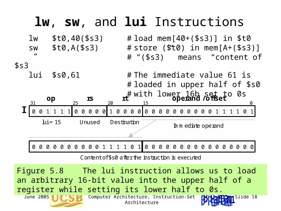
Figure 5.8 The lui instruction allows us to load an arbitrary 16-bit value into the upper half of a register while setting its lower half to 0s.
0
0 0 0 0 0 0 0 0 0 0 0 1 1 1 1 1 0 0 0 0 0 0 0 0 0 0 0 0 0 0 0 0
0 0 0 0 0 0 0 0 0 0 0 1 1 1 1 1 0 0 1 1 1 1 1 0 0 0 0 0 0 0 0
31 25 20 15 0
lui = 15 Destination Unused Immediate operand
op rs rt operand / offset
I
Content of $s0 after the instruction is executed
lw $t0,40($s3) # load mem[40+($s3)] in $t0 sw $t0,A($s3) # store ($t0) in mem[A+($s3)]
# “($s3)” means “content of
$s3” lui $s0,61 # The immediate value 61 is
# loaded in upper half of $s0 # with lower 16b set to 0s

June 2005 Computer Architecture, Instruction-Set Architecture Slide 19
Initializing a RegisterExample 5.2
Show how each of these bit patterns can be loaded into $s0:
0010 0001 0001 0000 0000 0000 0011 1101 1111 1111 1111 1111 1111 1111 1111 1111
Solution
The first bit pattern has the hex representation: 0x2110003d
lui $s0,0x2110 # put the upper half in $s0 ori $s0,0x003d # put the lower half in $s0
Same can be done, with immediate values changed to 0xffff for the second bit pattern. But, the following is simpler and faster:
nor $s0,$zero,$zero # because (0 0) = 1

June 2005 Computer Architecture, Instruction-Set Architecture Slide 20
5.5 Jump and Branch Instructions
Unconditional jump and jump through register instructions
j verify # go to mem loc named “verify” jr $ra # go to address that is in $ra;
# $ra may hold a return address
Figure 5.9 The jump instruction j of MiniMIPS is a J-type instruction which is shown along with how its effective target address is obtained. The jump register (jr) instruction is R-type, with its specified register often being $ra.
0
0 0 0 0 0 0 0 1 1 1 1 1 0 0 0 0 0 0 0 0 0 0 0 0 0 0 0 0
0 0 0 0 0 0 0 0 0 0 0 1 1 1 1 1 0 0 1 0 0 0 0 0 0 0 0 0
31 0
j = 2
op jump target address
J
Effective target address (32 bits)
25
From PC
0 0
x x x x
0 0 0 1 1 1 1 0 0 0 0 0 0 0 0 0 0 0 0 0 0 0 0 0 0 0 1 1 0 0 0 0
31 25 20 15 0
ALU instruction
Source register
Unused
op rs rt
R rd sh
10 5 fn
Unused Unused jr = 8
June 2005 Computer Architecture, Instruction-Set Architecture Slide 21
Conditional Branch Instructions
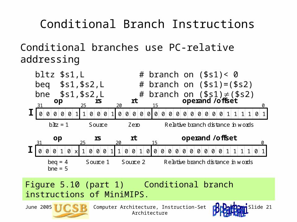
Figure 5.10 (part 1) Conditional branch instructions of MiniMIPS.
Conditional branches use PC-relative addressing
bltz $s1,L # branch on ($s1)< 0 beq $s1,$s2,L # branch on ($s1)=($s2) bne $s1,$s2,L # branch on ($s1)($s2)
0 1 0 0 0 0 0 0 0 0 0 0 0 0 0 0 1 1 1 1 1 0 0 1 1 0 0 0 0 0 0
31 25 20 15 0
bltz = 1 Zero Source Relative branch distance in words
op rs rt operand / offset
I 0
1 1 0 0 x 0 0 0 0 0 0 0 0 0 0 0 1 1 1 1 1 0 0 1 1 0 0 0 0 0 0
31 25 20 15 0
beq = 4 bne = 5
Source 2 Source 1 Relative branch distance in words
op rs rt operand / offset
I 1
June 2005 Computer Architecture, Instruction-Set Architecture Slide 22
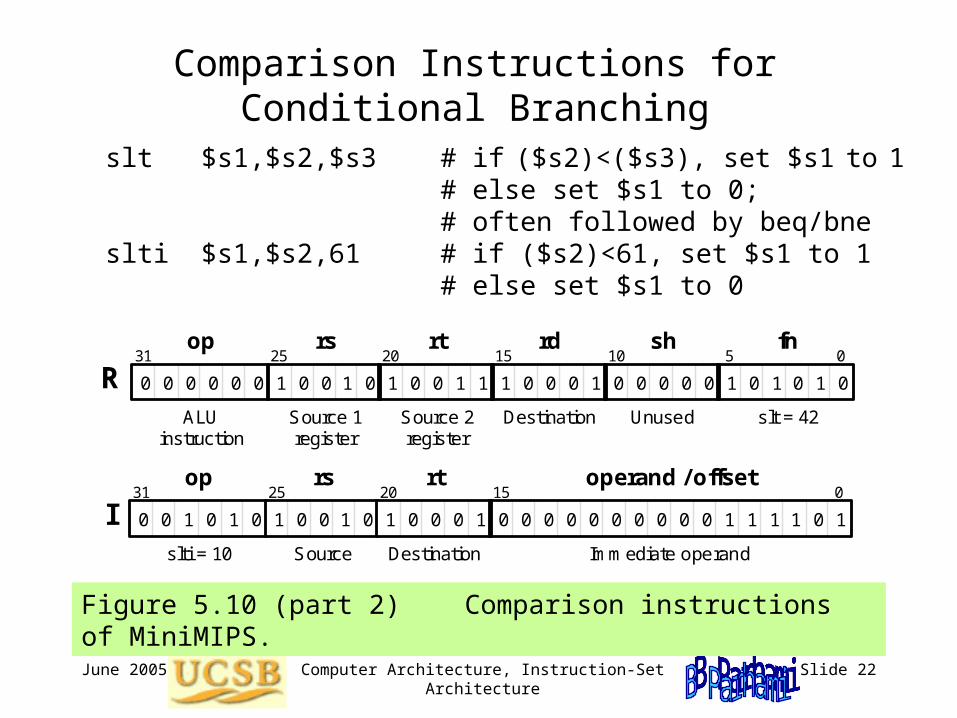
Comparison Instructions for Conditional Branching
Figure 5.10 (part 2) Comparison instructions of MiniMIPS.
slt $s1,$s2,$s3 # if ($s2)<($s3), set $s1 to 1 # else set $s1 to 0;
# often followed by beq/bne slti $s1,$s2,61 # if ($s2)<61, set $s1 to 1 # else set $s1 to 0
1 1 1 0 1 1 1 0 0 0 1 1 0 0 0 0 0 0 0 0 0 0 0 0 0 0 0 0 1 1 0 0
31 25 20 15 0
ALU instruction
Source 1 register
Source 2 register
op rs rt
R rd sh
10 5 fn
Destination Unused slt = 42
1 1 1 0 0 0 0 0 0 0 0 0 0 0 0 0 1 1 1 1 1 0 0 1 1 0 0 0 0 0 0
31 25 20 15 0
slti = 10 Destination Source Immediate operand
op rs rt operand / offset
I 1

June 2005 Computer Architecture, Instruction-Set Architecture Slide 23
Examples for Conditional Branching
If the branch target is too far to be reachable with a 16-bit offset (rare occurrence), the assembler automatically replaces the branch instruction beq $s0,$s1,L1 with:
bne $s1,$s2,L2 # skip jump if (s1)(s2)
j L1 # goto L1 if (s1)=(s2) L2: ...
Forming if-then constructs; e.g., if (i == j) x = x + y
bne $s1,$s2,endif # branch on ij add $t1,$t1,$t2 # execute the “then”
partendif: ...
If the condition were (i < j), we would change the first line to:
slt $t0,$s1,$s2 # set $t0 to 1 if i<j beq $t0,$0,endif # branch if ($t0)=0;
# i.e., i not< j or ij
June 2005 Computer Architecture, Instruction-Set Architecture Slide 24
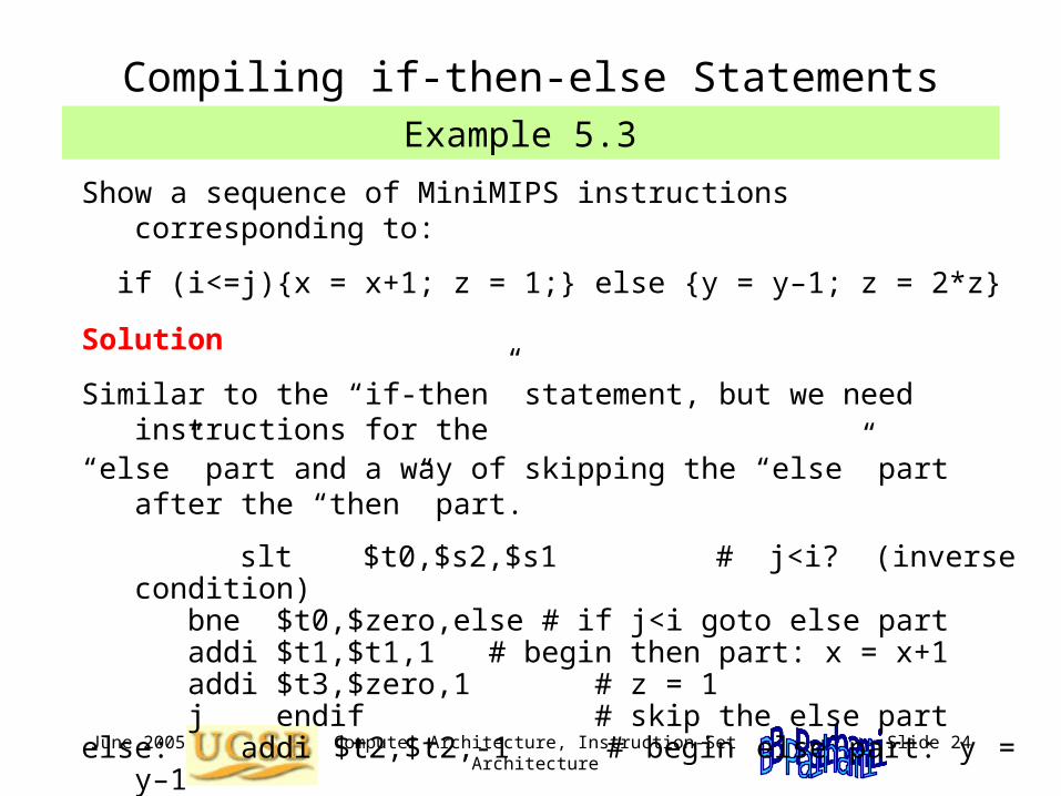
Example 5.3
Compiling if-then-else Statements
Show a sequence of MiniMIPS instructions corresponding to:
if (i<=j){x = x+1; z = 1;} else {y = y–1; z = 2*z}
Solution
Similar to the “if-then” statement, but we need instructions for the“else” part and a way of skipping the “else” part after the “then” part.
slt $t0,$s2,$s1 # j<i? (inverse condition) bne $t0,$zero,else # if j<i goto else part addi $t1,$t1,1 # begin then part: x = x+1 addi $t3,$zero,1 # z = 1 j endif # skip the else part
else: addi $t2,$t2,-1 # begin else part: y = y–1 add $t3,$t3,$t3 # z = z+z
endif:...

June 2005 Computer Architecture, Instruction-Set Architecture Slide 25
5.6 Addressing Modes
Figure 5.11 Schematic representation of addressing modes in MiniMIPS.
Addressing Instruction Other elements involved Operand
Implied
Immediate
Register
Base
PC-relative
Pseudodirect
Some place in the machine
Extend, if required
Reg file Reg spec Reg data
Memory Add
Reg file
Mem addr
Constant offset
Reg base Reg data
Mem data
Add
PC
Constant offset
Memory
Mem addr Mem
data
Memory Mem data
PC Mem addr

June 2005 Computer Architecture, Instruction-Set Architecture Slide 26
Example 5.5
Finding the Maximum Value in a List of Integers
List A is stored in memory beginning at the address given in $s1. List length is given in $s2. Find the largest integer in the list and copy it into $t0.
Solution
Scan the list, holding the largest element identified thus far in $t0.
lw $t0,0($s1) # initialize maximum to A[0]addi $t1,$zero,0 # initialize index i to 0
loop: add $t1,$t1,1 # increment index i by 1beq $t1,$s2,done # if all elements examined,
quitadd $t2,$t1,$t1 # compute 2i in $t2add $t2,$t2,$t2 # compute 4i in $t2 add $t2,$t2,$s1 # form address of A[i] in $t2 lw $t3,0($t2) # load value of A[i] into $t3slt $t4,$t0,$t3 # maximum < A[i]?beq $t4,$zero,loop # if not, repeat with no
changeaddi $t0,$t3,0 # if so, A[i] is the new
maximum j loop # change completed; now repeat
done: ... # continuation of the program
June 2005 Computer Architecture, Instruction-Set Architecture Slide 27
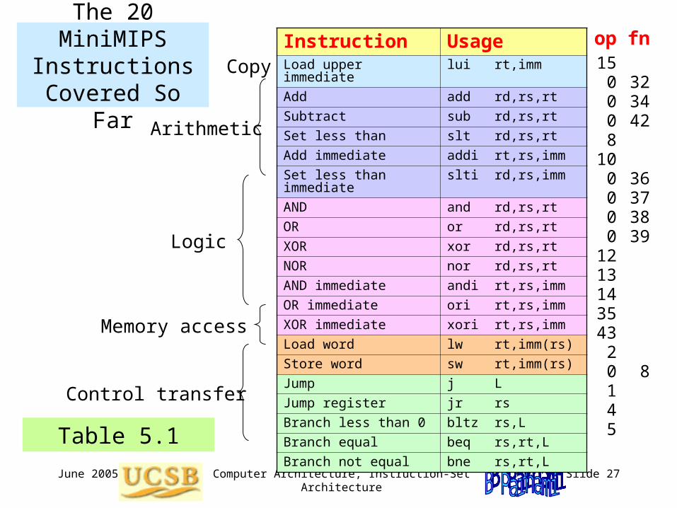
The 20 MiniMIPS Instructions
Covered So Far
Instruction UsageLoad upper immediate lui rt,imm
Add add rd,rs,rt
Subtract sub rd,rs,rt
Set less than slt rd,rs,rt
Add immediate addi rt,rs,imm
Set less than immediate slti rd,rs,imm
AND and rd,rs,rt
OR or rd,rs,rt
XOR xor rd,rs,rt
NOR nor rd,rs,rt
AND immediate andi rt,rs,imm
OR immediate ori rt,rs,imm
XOR immediate xori rt,rs,imm
Load word lw rt,imm(rs)
Store word sw rt,imm(rs)
Jump j L
Jump register jr rs
Branch less than 0 bltz rs,L
Branch equal beq rs,rt,L
Branch not equal bne rs,rt,L
Copy
Control transfer
Logic
Arithmetic
Memory access
op15
0008
100000
1213143543
20145
fn
323442
36373839
8 Table 5.1


