64
Computer Architecture VLIW - multi-cores - hardware multi-threading 1
Computer ArchitectureVLIW - multi-cores - hardware multi-threading
1
Summary of explicit concurrency (1)
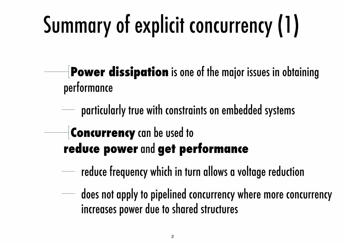
Power dissipation is one of the major issues in obtaining performance
particularly true with constraints on embedded systems
Concurrency can be used to reduce power and get performance
reduce frequency which in turn allows a voltage reduction
does not apply to pipelined concurrency where more concurrency increases power due to shared structures
2

Summary of explicit concurrency (2)
VLIW is the simplest form of explicit concurrency it reduces hardware complexity, hence power requirements
drawbacks are code compatibility and intolerance to cache misses
EPIC attempts to resolve these problems in VLIW
this adds complexity and requires large caches to get good performance
Multi-cores are scalable but need new programming models
the big question is - can we design general purpose multi-cores?
the Concurrent Systems course explores this research direction
3
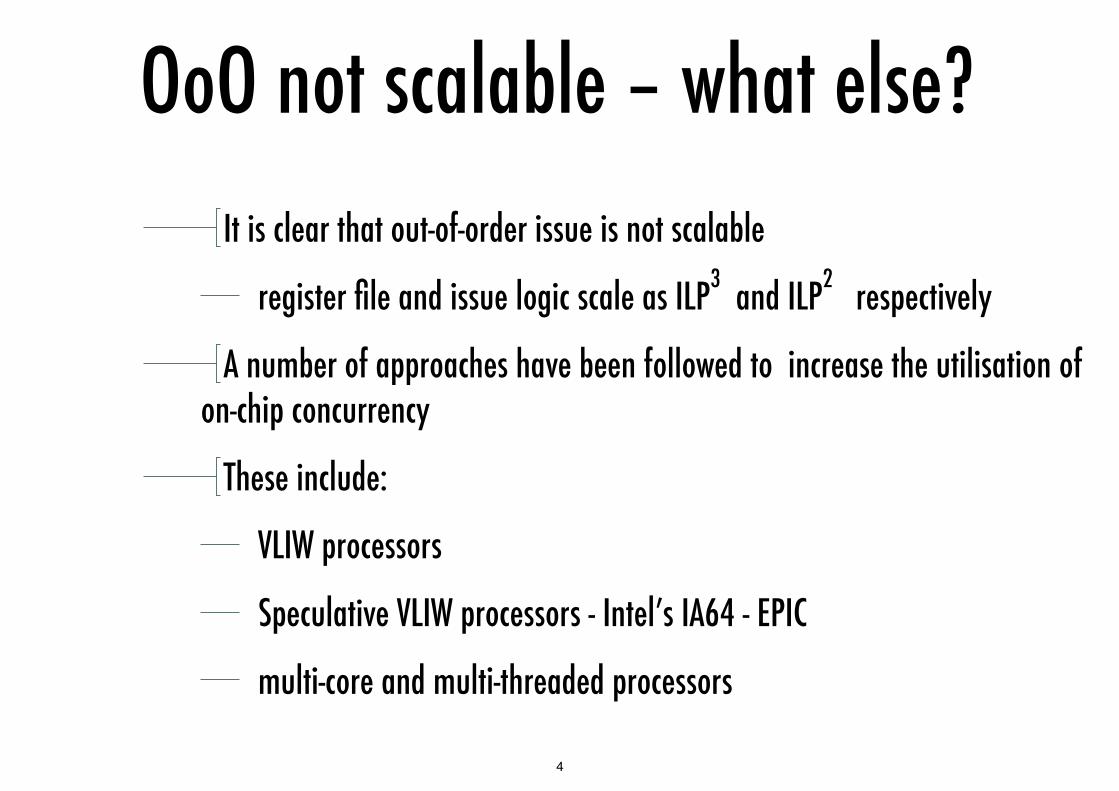
OoO not scalable – what else?It is clear that out-of-order issue is not scalable
register file and issue logic scale as ILP3 and ILP2 respectively
A number of approaches have been followed to increase the utilisation of on-chip concurrency
These include:
VLIW processors
Speculative VLIW processors - Intel’s IA64 - EPIC
multi-core and multi-threaded processors
4

The power wall
5
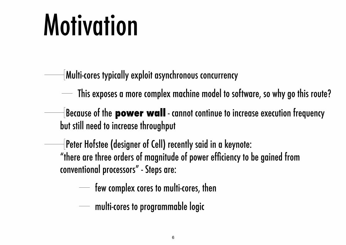
MotivationMulti-cores typically exploit asynchronous concurrency
This exposes a more complex machine model to software, so why go this route?
Because of the power wall - cannot continue to increase execution frequency but still need to increase throughput
Peter Hofstee (designer of Cell) recently said in a keynote:“there are three orders of magnitude of power efficiency to be gained from conventional processors” - Steps are:
few complex cores to multi-cores, then
multi-cores to programmable logic
6

Technology scaling - theoryThis is not simple as it involves playing with many
parameters such as voltage, frequency, capacitance etc.
A technology scaling step aims to:
reduce gate delay by 30% increasing frequency by 43%
double transistor density (line width reduced by 1.4)
reduce transition energy by 65% saving 50% power (at 43% increase in frequency) - reducing Vdd
7
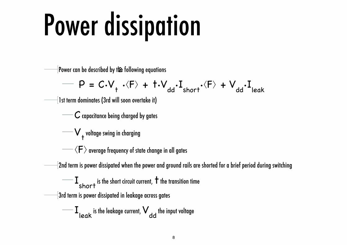
Power dissipationPower can be described by the following equations
P = C∙Vt
2
∙⟨F⟩ + t∙Vdd∙Ishort∙⟨F⟩ + Vdd∙Ileak 1st term dominates (3rd will soon overtake it)
C capacitance being charged by gates
Vt voltage swing in charging
⟨F⟩ average frequency of state change in all gates
2nd term is power dissipated when the power and ground rails are shorted for a brief period during switching
Ishort is the short circuit current, t the transition time
3rd term is power dissipated in leakage across gates
Ileak is the leakage current, Vdd the input voltage
8

Scaling predictionShekhar Borkar (2007) Thousand Core Chips—A Technology Perspective, DAC 2007, San Diego, California, USA. DAC
2007, June 4–8, 2007, San Diego, California, USA.
9
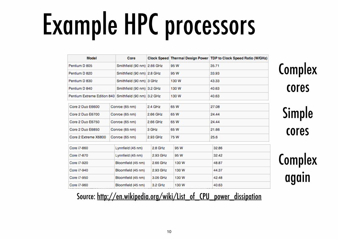
Example HPC processors
Source: http://en.wikipedia.org/wiki/List_of_CPU_power_dissipation
Complex cores
Simple cores
Complex again
10

Power-related constraintsProblems caused by power dissipation (heat):
thermal runaway - the leakage currents of transistors increase with temperature
electro-migration diffusion – metal migration with current increases with temperature (fuse effect)
electrical parameters shift - CMOS gates switch faster when cold (cf “to over-clock get some liquid nitrogen!”)
silicon interconnections fatigue (expand and contract with temp. swings)
package related failure
Power dissipation constraints (e.g. ~100W per package) provide an upper limit on power usage, and thus component frequency and input voltage
11

Cooling costs
From: S.H. Gunther, Managing the impact of increasing microprocessor power consumption, Intel Technology Journal Q1, 2001
12
Impact on performance
High demand for portable devices, e.g. mobile phones, etc. - 95% of CMOS silicon production!
Extensive use of multimedia features requires substantial performance (throughput) in these devices
However power usage is constrained by battery life !
The energy from a battery will not grow significantly in the near future due to technological and safety reasons
The main product feature is: hours of use and hours of standby
There is a need for techniques to improve energy efficiency without penalising performance
13

Low-power strategiesOS level - partitioning, power down while idle
Software level - regularity, locality, concurrency
Architecture level : pipelining, redundancy, data encoding
ISA level - architectural design using explicit concurrency, conservative rather than speculative execution, memory hierarchy
Circuit/logic level - logic styles, transistor sizing, energy recovery
Choice of logic family, conditional clocking, adiabatic circuits, asynchronous design
Technology level - Threshold reduction, multi-threshold devices
S. Younis T. Knight, “Asymptotically zero energy computing using split- level charge recovery logic”, Technical Report AITR-1500, MIT AI Laboratory June 1994.
Michael P. Frank, “Physical Limits of Computing. Lecture #24 Adiabatic CMOS”, Spring 2002.
14

Reducing power - system levelThe main technique for minimising power dissipated for a given chip architecture and
technology implementation is to adjust the frequency and/or voltage supply
Reducing voltage increases gate delay and reduces operating frequency
Fmax = K∙(Vdd-Vt)2
Most microprocessor systems reduce frequency when processor is idle
Many signal processors reduce voltage and frequency depending on system load
ARM are investigating algorithm-controlled dynamic voltage scaling - e.g. MPEG encoding based on image flow complexity
The more complex the image flow (artifacts moving in the image) the more computation is required hence the algorithm can predict the performance - frequency - voltage required
15
Reducing power - architecture level
Avoid speculation and issue instructions conservatively
any misspredicted speculation requires power dissipation for no tangible results
Organise and power up memory by banks independently
sequential access to memory
Avoid unecessary operations
e.g. reading registers where data is bypassed
Reduce number of swings on data busses
e.g. use grey codes to exploit locality
only send bits that change - form of data compression
16
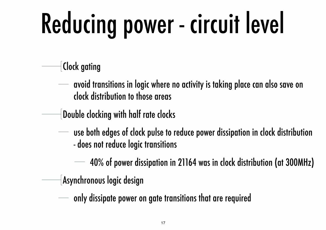
Reducing power - circuit levelClock gating
avoid transitions in logic where no activity is taking place can also save on clock distribution to those areas
Double clocking with half rate clocks
use both edges of clock pulse to reduce power dissipation in clock distribution - does not reduce logic transitions
40% of power dissipation in 21164 was in clock distribution (at 300MHz)
Asynchronous logic design
only dissipate power on gate transitions that are required
17
Multi-core processors and hw multithreading
Explicit concurrency in hardware, explicit concurrency in low-level software
18

Pollack’s rule
This is an empirical trend observed by Pollack
Sequential performance is roughly proportional to the square root of the core’s complexity
i.e. linear with line width not as the square
double the logic to get 140% increase in performance
Multi-core however can deliver close to linear increase for loosely coupled work loads if overheads of concurrency can be minimised
19

Less power for same performance
Use frequency-voltage scaling for dynamic power, ie reduce f and reduce V
Dynamic power proportional to f and V2, single core throughput proportional to 1/f
2 processors running at f/2 can give the same performance as one running at f for scalable computation
The ratio of dynamic power dissipated is
1 core at f proportional to: f∙V12, 2 cores at f/2 proportional to: 2∙(f/2)∙V2
2 = f∙V2
2
power saving of (V2/V1)2
Hence spread work across cores through concurrency, reduce power dissipated by a square of the voltage difference - also multiple cores help spread dissipation across the chip
20
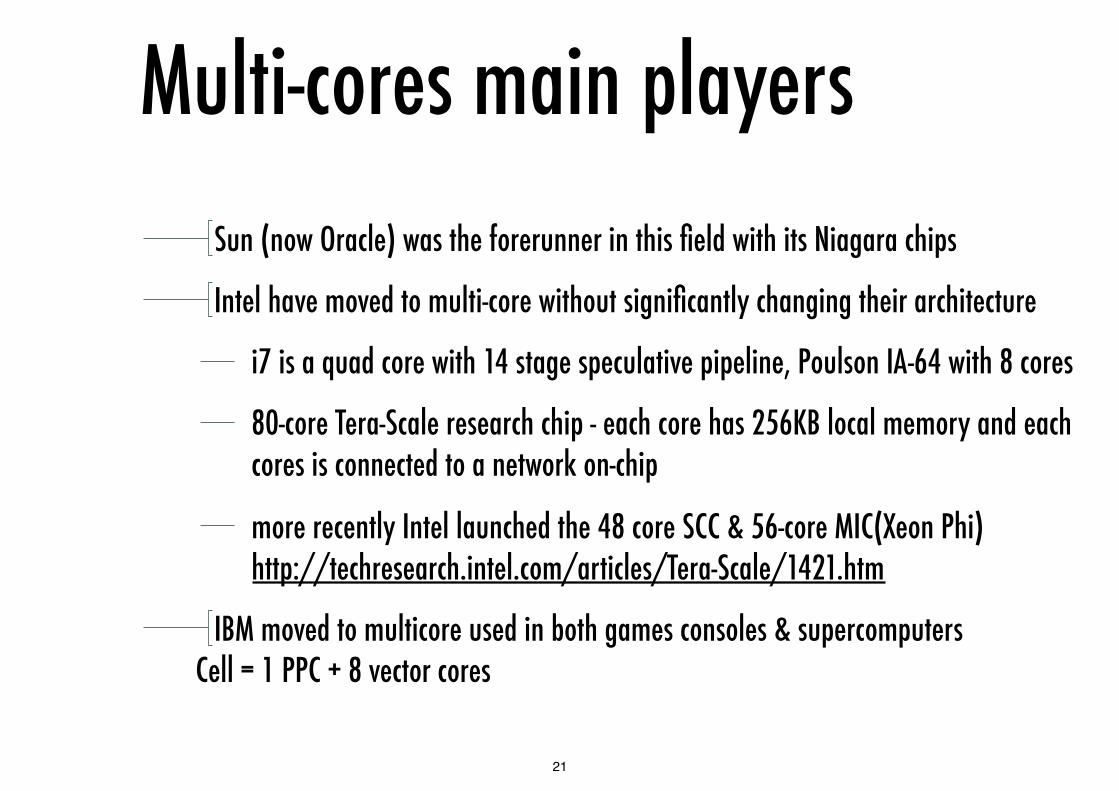
Multi-cores main playersSun (now Oracle) was the forerunner in this field with its Niagara chips
Intel have moved to multi-core without significantly changing their architecture
i7 is a quad core with 14 stage speculative pipeline, Poulson IA-64 with 8 cores
80-core Tera-Scale research chip - each core has 256KB local memory and each cores is connected to a network on-chip
more recently Intel launched the 48 core SCC & 56-core MIC(Xeon Phi) http://techresearch.intel.com/articles/Tera-Scale/1421.htm
IBM moved to multicore used in both games consoles & supercomputers Cell = 1 PPC + 8 vector cores
21

Latency issues
130 nm
100 nm
70 nm
35 nm
20 mm chip edge
Analytically … Qualitatively …
Bits reachable in one clock cycle clock cycle defined by 8, 16 or optimal (fSIA) number of fan-out-of-4 gates
22

Multi-core implies multi-threading per core
Larger number of cores implies larger average distance, hence latency, between cores and cores/memory
In turn this implies larger mandatory off-core communication overheads for single threads
To maximize utilization and throughput, cores should fetch instructions from independent threads to tolerate latencies
This must be possible at the finest grain (individual loads and stores), hence the need for hardware thread scheduling in the fetch/issue stage
23

Multi-thread main playersSun/Oracle again with Niagara chips - 8 threads/core
Intel recycled the SMT plans of 21464 as “HyperThreading”, found in P4 and again in Core i7 Nehalem, 2 threads/core
Also found again in Itanium 2, 2 threads/core
Two main strategies for scheduling hw threads: control flow scheduling and dataflow scheduling
24

Control flow schedulingIn control flow scheduling threads are identified for scheduling
using control flow triggers
e.g. cache miss on a load
branches
Threads are selected for execution from ready threads (e.g. round robin scheduling)
On a trigger e.g. branch or miss the thread is suspended until resolution – e.g. Niagara, Itanium 2
25
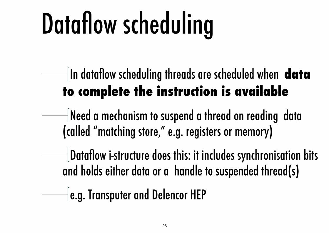
Dataflow scheduling
In dataflow scheduling threads are scheduled when data to complete the instruction is available
Need a mechanism to suspend a thread on reading data (called “matching store,” e.g. registers or memory)
Dataflow i-structure does this: it includes synchronisation bits and holds either data or a handle to suspended thread(s)
e.g. Transputer and Delencor HEP
26
Programming issuesMultiple cores and multiple threads per core appear as
different processors to software, each with their own instruction stream (program counter sequence)
Major departure from the “simple” Turing/Von Neumann model, convergence with parallel programming of HPC
Explicit hardware concurrency requires parallel machine models to abstract the hardware, which in turn entail concurrent programming models
27

Programming models
3 phases to program an explicit concurrent chip:
decompose problem into concurrent sub-problems
express sub-problems as communicating threads
map threads onto chip components
Different programming environments automate these
28

Who’s in charge of explicit concurrency?
Programming styles
Task of programmer Task of automated stack (compiler + run-time system + hardware)
Find dependencies
Decompose in threads
Map threads
Find dependencies
Decompose in threads
Specify problemHIGH-LEVEL, FUNCTIONAL
VECTORED / ANNOTATED
EXPLICIT THREADS, IMPLICIT PLACEMENT
(eg. SQL, Haskell, SDF)
(eg. OpenMP, FORTRAN)
(eg. Cilk, TBB, pthreads)Map threads
Schedule instructions
EXPLICIT THREADSEXPLICIT PLACEMENT
(eg. MPI, GrandCentral Dispatch)
29

Programming issues (revisited)
Parallel programming models at each level of abstraction come in two flavors: implicit vs. explicit communication
Implicit communication based on shared memory or distributed software cache protocols, which do not scale
Explicit communication leaves the program in charge of scalability, but is more difficult to program
These issues are revisted in the Concurrent Programming course
30

Granularity issuesOut of order execution gives compatibility with the minimum
concurrency – 1 thread
To obtain portability with explicitly parallel code need to expose all concurrency in the code
then auto sequentialise to reduce overheads of concurrency creation and management
Both threading and auto sequentialisation can be managed in hardware – the latter has not appeared in commercial chips yet
31

Example multi-cores
32

IBM PowerXCell 8i
33
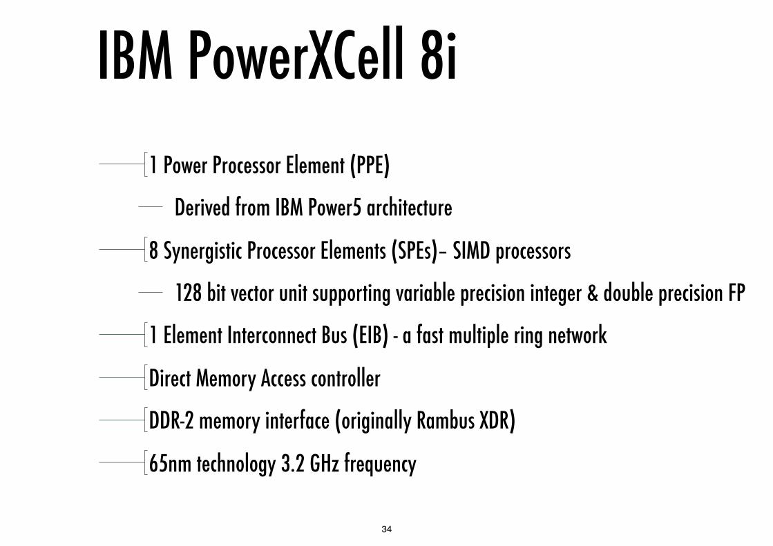
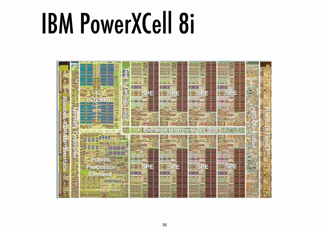
IBM PowerXCell 8i1 Power Processor Element (PPE)
Derived from IBM Power5 architecture
8 Synergistic Processor Elements (SPEs)– SIMD processors
128 bit vector unit supporting variable precision integer & double precision FP
1 Element Interconnect Bus (EIB) - a fast multiple ring network
Direct Memory Access controller
DDR-2 memory interface (originally Rambus XDR)
65nm technology 3.2 GHz frequency
34
IBM PowerXCell 8i
35

Cell’s PPE64 bit RISC processor, PowerPC ISA
32/32 KByte L1 I- and D-caches
512KB L2 cache
64GB/s load-store bandwidth
In-order execution, 2-way issue - 2 hardware threads
Optionally equipped with AltiVec SIMD extensions
36
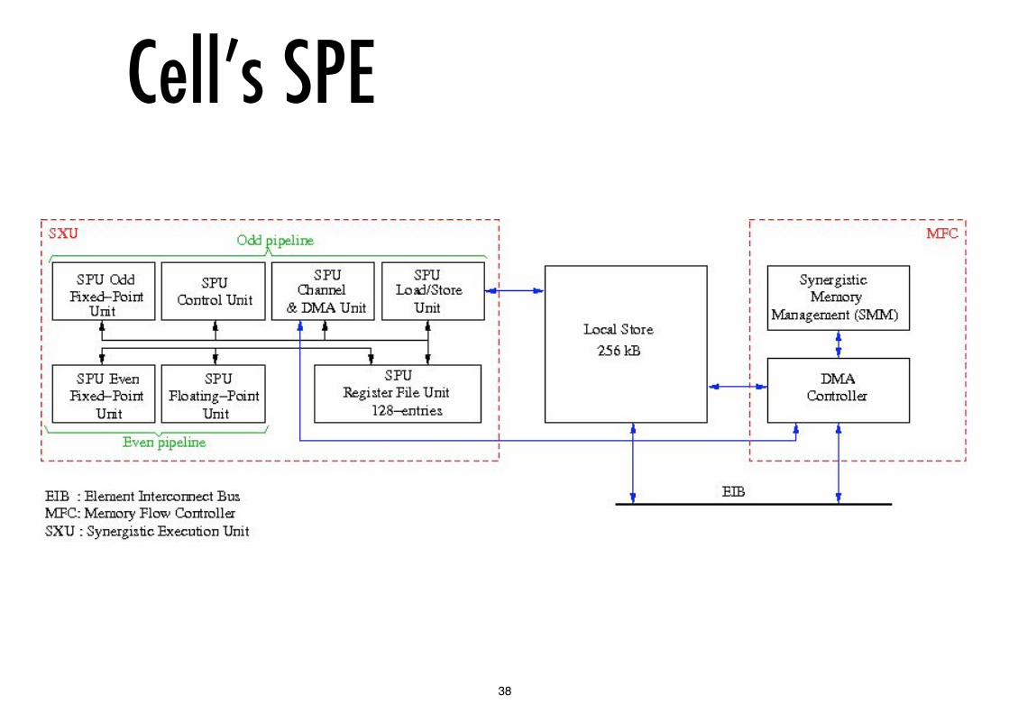
Cell’s SPEIndependent processors each runs an application thread
has its own 256KB private local store
has DMA access to coherent shared memory of PPE
It is a SIMD vector processor with an Altivec-like ISA
128 by 128 bit registers used as 16 x 8 bit, 8 x 16 bit, 4 x 32bit, 2 x 64bit
4 single precision FP units (latest version supports 2 x DP)
4 integer units
Dual issue - 8 x 32 bit operations per cycle,
max 25.6 GFLOP/s with single precision FP
37
Cell’s SPE
38

Cell’s SPE pipeline
39

Tilera TILE64
40

Tilera TILE64
8 x 8 grid of 3-way in-order VLIW pipelines, MIPS ISA
5 MB on-chip cache
up to 443 GIPS
31 TB/s internal bandwidth, 50GB/s I/O bandwidth
700-866MHz frequency 15-22W @ 700MHz
41

Intel Single-Chip Cloud
48 P54C cores (Pentium I), mesh interconnect, no cache coherency in hardware
42

Intel Single-Chip Cloud
8 voltage islands
28 frequency islands
Independent V/F for I/O and memory
43
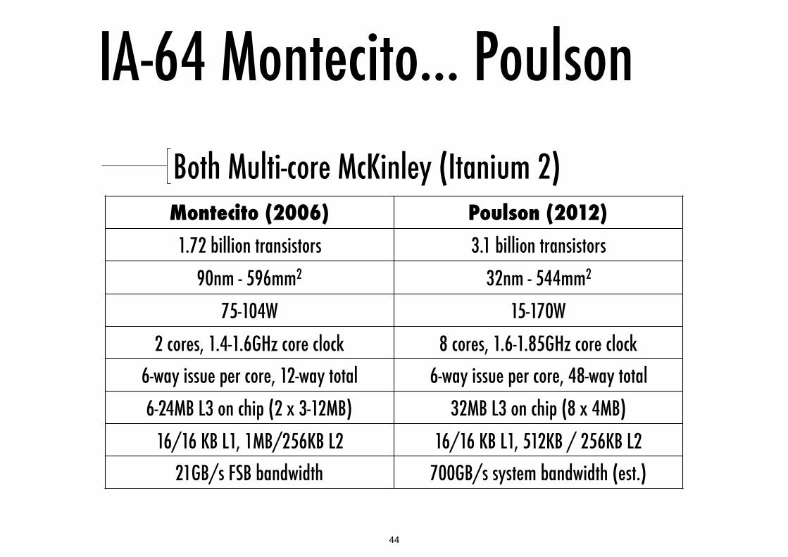
IA-64 Montecito... PoulsonBoth Multi-core McKinley (Itanium 2)Montecito (2006) Poulson (2012)
1.72 billion transistors 3.1 billion transistors90nm - 596mm2 32nm - 544mm2
75-104W 15-170W2 cores, 1.4-1.6GHz core clock 8 cores, 1.6-1.85GHz core clock
6-way issue per core, 12-way total 6-way issue per core, 48-way total6-24MB L3 on chip (2 x 3-12MB) 32MB L3 on chip (8 x 4MB)
16/16 KB L1, 1MB/256KB L2 16/16 KB L1, 512KB / 256KB L221GB/s FSB bandwidth 700GB/s system bandwidth (est.)
44

IA-64 Poulson
45
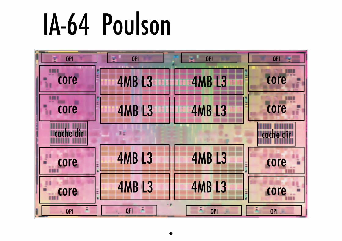
IA-64 Poulson
core
core
core
core
core
core
core
core 4MB L3 4MB L3
4MB L34MB L3
4MB L3 4MB L3
4MB L34MB L3
cache dir cache dir
QPI QPI QPI QPI
QPI QPI QPI QPI
46

SPARC Niagara T1/2/3/4
47

Niagara in a nutshellDeparture from the beaten road of sequential performance:
focus on multi-cores and multi-threading
Niagara T1 (2005): 8 cores, 4 threads/core, 1-1.4GHz
Niagara T2 (2007): 8 cores, 8 threads/core, 1.2-1.6GHz
Niagara T3 (2009): 16 cores, 8 threads/core, 1.67GHz
2 single-issue in-order pipelines / core, 4 threads per pipeline
48
Niagara T3 floorplan
49
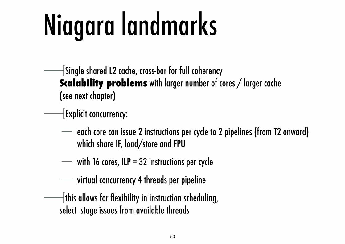
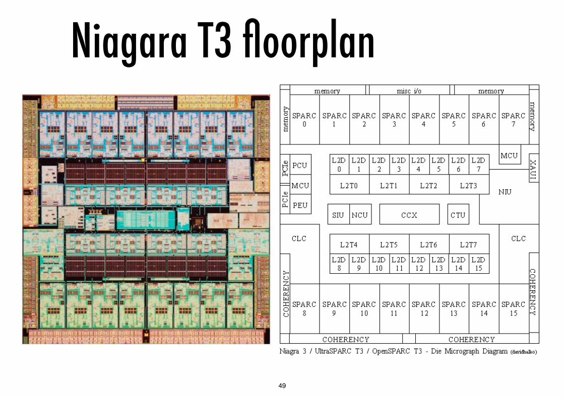
Niagara landmarksSingle shared L2 cache, cross-bar for full coherency
Scalability problems with larger number of cores / larger cache (see next chapter)
Explicit concurrency:
each core can issue 2 instructions per cycle to 2 pipelines (from T2 onward) which share IF, load/store and FPU
with 16 cores, ILP = 32 instructions per cycle
virtual concurrency 4 threads per pipeline
this allows for flexibility in instruction scheduling, select stage issues from available threads
50

Niagara T1 pipeline
Source: RealWorldTech
51
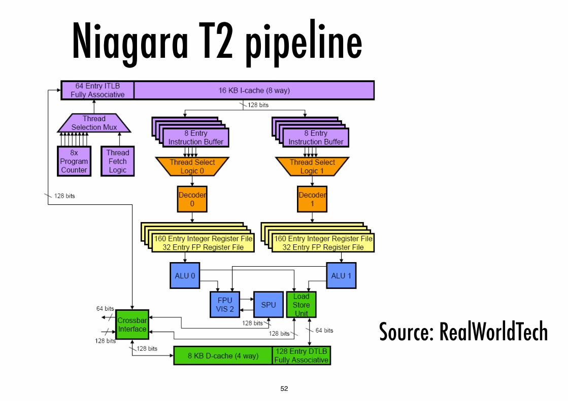
Niagara T2 pipeline
Source: RealWorldTech
52

Niagara register filesSPARC ISA supports register windows
for n overlapping windows register file comprises 16 + n*16 registers, where each window has 8 global, 8 local, 8 input and 8 output registers
output of one window is the input to the next
Niagara provides 4 independent thread contexts per pipeline
8 per core in two groups (strands 0..3 and 4..7) each file has 8 register windows – 144 registers per thread giving a total of 1152 registers per core
Each register file has 5 ports, uses “3D addressing” to exploit the fact that only one window per thread is active at a time - this design is scalable
53
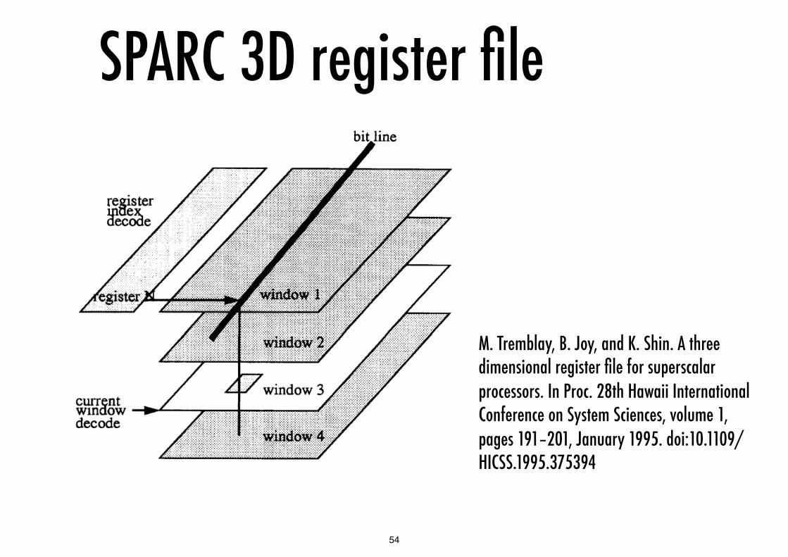
SPARC 3D register file
M. Tremblay, B. Joy, and K. Shin. A three dimensional register file for superscalar processors. In Proc. 28th Hawaii International Conference on System Sciences, volume 1, pages 191–201, January 1995. doi:10.1109/HICSS.1995.375394
54

Niagara thread schedulingHow are SPARC threads defined?
threads are defined by OS call setting up a thread, its stack and its PC using a system mode instr.
How scheduled?
Active threads are scheduled on an LRU basis for fairness threads become inactive on branch instructions and when stalled waiting for memory
Thread scheduling assumes an L1 cache hit
Thread management costs:
creation – performed in software, so relatively high cost but can be reduced using thread pooling
scheduling – zero cycle thread switching: new threads are selected for execution on every cycle
Synchronisation – depends on where test and set address resides in memory hierarchy
55

Niagara memory (T3)L1 shared between 2 pipelines
L2 shared between all cores
It has 16 banks with two X-bar switches between groups of 8 cores
Switch is approximately 5% of core area
Reads at 180 Gbytes/s writes at 90 Gbytes/s
L2 cache 6 MByte, 64 Byte lines - 16-way set associative
Memory interfaces 4 x DDR 3, fully buffered
Memory system designed for throughput
56

Niagara T4 - yet differentDeparture from the T1/T2/T3: focuses again on
sequential performance
Introduces OoO issue and branch prediction
The extra logic per core is compensated by fewer cores (8)
Introduces a “Work Register File” for storage after register renaming
57

Niagara T4 pipeline
58

Niagara T4 pipeline
59

© Chris Jesshope 2008-2011, Raphael Poss 2011
Niagara T4 pipelineBefore pick: only 1 thread per stage
Pick to commit: multiple threads per stage
Commit: 1 thread per stage
60
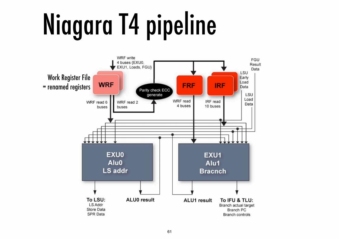
Niagara T4 pipeline
Work Register File = renamed registers
61

© Chris Jesshope 2008-2011, Raphael Poss 2011
Niagara T4Telltale signs that sequential performance matters again:
new 128KB L2 cache per core, shared L3
OoE/BP logic
Higher frequency (up to 3GHz)
62

Niagara T4 sequential performance
63

Niagara power usageChip TDP Nominal Technology Parallelism
T1 72W 378 mm2, 90nm
8 cores, 32 threads
T2 123W 95W 342mm2, 65nm
8 cores, 64 threads
T3 139W 75W 371mm2, 40nm
16 cores, 128 threads
T4 240W 103W 403mm2, 40nm
8 cores, 64 threads
64


