COMPUTER ASSISTED LEARNING OF JAPANESE KANJI Adam D. Horne Problem Report submitted to the College of Engineering and Mineral Resources At West Virginia University In partial fulfillment of requirements For the degree of Master of Science In Computer Science Frances L. Van Scoy, Ph.D., Chair John Atkins, Ph.D. James D. Mooney, Ph.D. Lane Department of Computer Science and Electrical Engineering Morgantown, West Virginia 2005 Keywords: haptic, height map, kanji, OpenGL, Open Haptics Toolkit, PHANTOM, Japanese language Copyright 2005 Adam D. Horne
Transcript
COMPUTER ASSISTED LEARNING OF JAPANESE KANJI
Adam D. Horne
Problem Report submitted to the College of Engineering and Mineral Resources
At West Virginia University In partial fulfillment of requirements
For the degree of
Master of Science In Computer Science
Frances L. Van Scoy, Ph.D., Chair John Atkins, Ph.D.
James D. Mooney, Ph.D.
Lane Department of Computer Science and Electrical Engineering
Morgantown, West Virginia 2005
Keywords: haptic, height map, kanji, OpenGL, Open Haptics Toolkit, PHANTOM, Japanese language Copyright 2005 Adam D. Horne
ABSTRACT
COMPUTER ASSISTED LEARNING OF JAPANESE KANJI
Adam D. Horne
The purpose of the program described in this problem report is to assist learners of Japanese kanji in remembering the order, direction, and number of strokes for a given kanji. Using OpenGL and the Open Haptics toolkit, the program allows the user to both see and feel the kanji. Using a PHANTOM haptic device, the user can trace the different strokes using a height map of the kanji or following arrows that show the direction and order of strokes.
iii
ACKNOWLEDGEMENTS
There are several people I would like to thank for their support and encouragement while I was working on my project. First I would like to thank Dr. Van Scoy for being my committee chairperson and allowing me to use many of the resources in the Virtual Environments Laboratory. I would also thank Dr. Atkins and Dr. Mooney for being on my committee. I appreciate the guidance I received from Asako No-sensei and Takamitsu Kawai when I had questions about the kanji. Also, I would like to thank my parents, Don and Debbie Horne, for their love and encouragement. Finally, I would like to thank the people and organizations that provided financial assistance during my graduate studies: Lane Department of Computer Science and Electrical Engineering, West Virginia University’s Department of Geology and Geography, and VRGIS.
The PHANTOM device................................................................................................................................ 1
CHAPTER 2: USING HEIGHT MAPS WITH HAPTICS ......................................4
Explanation of Height Maps........................................................................................................................ 4
Previous Use of Height Maps in Haptic Programs .................................................................................... 5
Alternatives to Height Maps........................................................................................................................ 6
CHAPTER 3: EXPLANATION OF JAPANESE KANJI.......................................8
Why Use Kanji?............................................................................................................................................ 8
Techniques for Learning Kanji ................................................................................................................. 10
Important Concepts in Writing Kanji ...................................................................................................... 11
CHAPTER 4: THE HAPTIC HEIGHT MAP PROJECT......................................14
An Explanation of OpenGL....................................................................................................................... 16
Design of Data Structures and Classes ..................................................................................................... 17 HeightMap Class ..................................................................................................................................... 17 StrokeOrder Class.................................................................................................................................... 19
Programming the OpenGL........................................................................................................................ 20 Problems with the Viewing Volume........................................................................................................ 21 render Function in the HeightMap Class................................................................................................. 22 render Function in the StrokeOrder Class ............................................................................................... 23 End Result of the OpenGL Code ............................................................................................................. 24
v
Programming the OpenHL........................................................................................................................ 25 Comparison of Haptic Programming Platforms....................................................................................... 25 Converting Existing OpenGL Code for use with OpenHL...................................................................... 27 render Function in the HeightMap Class................................................................................................. 28 render Function in the StrokeOrder Class ............................................................................................... 29 End Result of the OpenHL Code ............................................................................................................. 29
Creating the Data Files .............................................................................................................................. 30 Creating the Height Maps........................................................................................................................ 30 Creating the Stroke Order Files ............................................................................................................... 31
CHAPTER 5: CONCLUSION ............................................................................32 Testing on a 600 MHz Pentium ............................................................................................................... 32 Testing on a 3.2 GHz Pentium................................................................................................................. 33 Suggested Improvements......................................................................................................................... 34 Uses in Other Programs ........................................................................................................................... 36
The idea for the Haptic Height Map program came from a toy for
children to help learn the letters of the alphabet. The toy was a wooden
block with the shapes of all the letters of the alphabet carved into the surface.
A child could use a stylus to trace the shapes of the letters and learn how to
write the letters through repetition. The English alphabet only has twenty-
six characters, so it is possible to fit the entire alphabet on one reasonably
sized wooden tablet.
The toy was a good tool for children to practice writing. The Haptic
Height Map program was written to simulate the writing toy in a virtual
environment. Japanese students are expected to learn eighty kanji during
their first year of school and almost two thousand by the time they graduate
from high school. It would be very impractical to produce a physical tool
like the alphabet toy for that many kanji. The Haptic Height Map program
creates a virtual representation of a kanji character through the use of height
maps that a user can feel and trace with a PHANTOM device.
The PHANTOM device
The PHANTOM is a computer peripheral that allows a computer user
to touch and feel virtual objects simulated by the computer. Haptic Height
2
Map was programmed and tested with a PHANTOM Omni using the Open
Haptics toolkit. The Open Haptics Library (OpenHL) integrates with the
Open Graphics Library (OpenGL), so most programs that can be written in
OpenGL can be modified to add a haptic interface.
Figure 1: The PHANTOM Omni
The PHANTOM is a force feedback device that allows the user to
touch and interact with virtual environments. It is comprised of a stylus
attached to a base by an arm. It offers six degrees of freedom and a wide
range of motion. The Open Haptics toolkit provides functionality to assign
material properties and forces such as friction and magnetic attraction and
repulsion to objects that are being modeled. The toolkit handles all force
3
effects so the programmer does not have to perform complex calculations for
physical properties. This allows the PHANTOM to simulate a realistic
haptic experience.
4
Chapter 2: Using Height Maps with Haptics
Height maps are used primarily to store height information for large
areas. They are used extensively in geographic simulations because they can
store a large amount of information in a compact way. Height maps have
been used in other haptic programs to simulate the creation of paintings[1].
Explanation of Height Maps
Figure 2: Height Map
5
Height maps are a storage device to hold height information for points
over a large area. Figure 2 shows an example of a height map with a wide
range of values. Height maps are normally stored as grayscale images. The
images have a set resolution on the x and y axes, and each point in the image
corresponding to an (x, y) coordinate has a value ranging from 0 to 255.
This value is the height value for that position in the image[2]. It is also
used to provide a color for that point, with 0 being black and 255 being
white.
Previous Use of Height Maps in Haptic Programs
Height maps have been used in haptic programs to simulate the way
that paint is applied to canvas. A program called IMPaSTo was created by a
group of researchers at the University of North Carolina at Chapel Hill that
uses a PHANTOM device to simulate the art of painting[1]. The program
uses the PHANTOM as a virtual brush and physically models the flow of
paint from the brush to a virtual canvas.
IMPaSTo uses multiple height maps to keep track of the depths of
different layers of paints that have been applied to the canvas. The height
map allows for two different states for the paint, wet and dry. If the top
layer of paint is wet, then paint from the canvas will interact with paint on
6
the brush to change the color. If the top layer is dry, then paint is applied on
top of the highest dry layer and creates a new height map for the wet layer.
Using multiple height maps allows the program to keep track of the
different layers of paint color and how this will affect the way the painting
looks[1]. Height maps are efficient for this type of application because for
any given point (x, y), only one value has to be stored for each layer to
record the depth of the paint. This can improve the efficiency in both
processing time and memory usage.
Alternatives to Height Maps
A program to simulate the haptic display of mathematical functions
was written by a group of researchers at the Virtual Environments
Laboratory at West Virginia University. It used a similar concept of carving
the shape of the function into a virtual object that allowed a user to feel the
mathematical function.
This program was written using strips of triangles by computing the y
values of points for a given x value. Instead of reading information stored in
a height map, all the values to be displayed are computed while the program
is running. The (x, y) coordinates are used to create a V-shaped groove in
the surface of the object with a set of eight triangles for each vertical strip on
the surface[4].
7
The method described in the use of the program to display
mathematical functions is not ideal for displaying kanji. Many kanji have
strokes that are completely vertical or have more than one stroke that
intersects a given vertical strip. The functionality used to display
mathematical functions is not able to handle more than one intersection for a
given vertical strip. The algorithm can not handle more than one
mathematical function due to this constraint[3]. It would also not be able to
render most kanji.
8
Chapter 3: Explanation of Japanese Kanji
The Japanese writing system uses two different character sets for
phonetic spelling: hiragana and katakana. Hiragana and katakana are
syllabaries with each character corresponding to one of the seventy-two
syllables of the Japanese language. Hiragana is used for spelling Japanese
words, and katakana is used mainly for spelling words borrowed from other
languages or adding emphasis to a word. Any Japanese word can be written
in hiragana and katakana. In addition to the two phonetic syllabaries,
Japanese also uses kanji, which are characters borrowed from the Chinese
writing system. Each character corresponds to one word, specific concept,
or general idea.
Why Use Kanji?
Since Japanese has two syllabaries that could be used to write with,
why is there a need for kanji? The reason is due to the way that Japanese
sentences are written. The Japanese language does not have the same
sentence structure or punctuation as English. English uses a sentence
structure in the pattern “subject verb object” whereas Japanese uses a
sentence structure of “subject object verb.” The English sentence, “I drink
water,” becomes, “I water drink,” in Japanese.
9
In Japanese, the function of a word is determined by the particle that
comes after it. The subject is usually followed by the particles “wa” or “ga,”
while the object is usually followed by “o” or sometimes “ga.” There are
other particles to denote possession, spatial relationships, where an action
takes place, and when an action takes place. The verb is usually the last
word in a sentence, so it does not need a particle to mark its function. It can
be difficult to determine when one of these syllables is a particle, because
these syllables can also be a part of words in the sentence.
A good example of where kanji can clear up confusion in a sentence is,
“Mom went to the dentist.” Table 1 shows this sentence written in English
and several different ways it could be written in Japanese.
Subject Part. Destination Part. Verb English Mom dentist to went. Romaji Haha wa haisha e ikimashita. Hiragana はは は はいしゃ へ いきました。 Hiragana and kanji
母 は 歯医者 へ 行きました。
Table 1: Example: Mom went to the dentist.
Spelled out in Romaji, a script to spell Japanese words using English
letters, it looks like, “Haha wa haisha e ikimashita.” This is not confusing in
Romaji because it uses the basic English punctuation of putting a space
between the words and particles. When written in hiragana, it looks like,
「ははははいしゃへいきました。」 This is confusing because the
10
particle “wa” is also the same character as “ha,” so the same character is
repeated four times, and the sentence is very hard to understand without a
context for the conversation in which it is used. The same sentence written
using hiragana and kanji looks like, 「母は歯医者へ行きました。」 The
use of kanji clears up any ambiguity caused due to the lack of punctuation,
so this is a good example of why kanji is so important for understanding the
Japanese writing system.
Techniques for Learning Kanji
The primary technique for learning Japanese kanji is repeatedly
writing the kanji in order to memorize it. The number of times a Japanese
student will write a kanji varies depending on how hard the kanji is to learn.
Simple kanji may only need to be written twenty times to be remembered.
Difficult kanji may need to be written as many as a hundred times or more.
Since the average Japanese student is expected to learn almost two thousand
kanji before graduating from high school, most students can expect to write
a hundred thousand or more kanji.
There are several shortcomings inherent in this form of learning. First,
the student needs to use either a brush or pen and have paper to write on.
Over the course of a student’s schooling, much paper is going to be wasted,
11
especially considering the huge number of kanji the student is going to write.
The student must also use a reference book with the stroke orders. The act
of looking from the paper the kanji is being written on to the book where the
stroke order is illustrated can cause distraction that makes it harder to
remember the kanji.
Important Concepts in Writing Kanji
There are several important concepts that should be considered when
learning and writing kanji. Kanji are comprised of a number of different
strokes, and the number of strokes in any given kanji can range from one to
eighty or more. Two things to consider when writing kanji are what type of
stroke to use and what order in which to write the strokes.
12
Figure 3: Example of Stops
The types of strokes are characterized by how the stroke ends. Kanji
are traditionally written with a brush, so there are several ways that a stroke
can be ended. The brush can be brought to a full stop and lifted to give a
blunt end to the stroke, or the brush can be lifted while still moving at the
end of the stroke to give a tapered end. Also, instead of lifting straight up
after a full stop, the brush can be moved slightly to the side to give the stoke
a little tail, called a “kick.” The different types of stops are illustrated in
Figure 3. When writing with a pen, there is no way to make a distinction
between a tapered and full stop, but the difference between a stop and a kick
should still be emphasized.
13
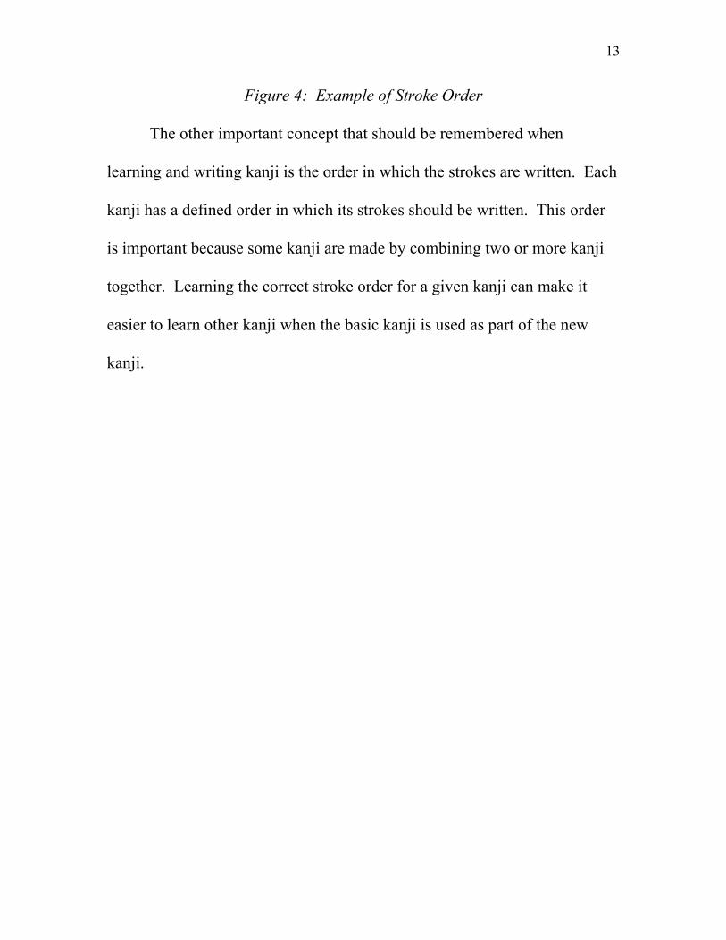
Figure 4: Example of Stroke Order
The other important concept that should be remembered when
learning and writing kanji is the order in which the strokes are written. Each
kanji has a defined order in which its strokes should be written. This order
is important because some kanji are made by combining two or more kanji
together. Learning the correct stroke order for a given kanji can make it
easier to learn other kanji when the basic kanji is used as part of the new
kanji.
14
Chapter 4: The Haptic Height Map Project
The goal of the Haptic Height Map project was to create a program
using height maps to display kanji with real-time visual and tactile feedback
that a student of Japanese kanji could use to learn kanji. By repeatedly
writing kanji, a student is training the hand and mind to recognize the shape
of the kanji and the feeling of writing it. This chapter will discuss how the
Haptic Height Map program is implemented and what functionality is
included to reach the goal of real-time visual and tactile feedback.
Scope
The Haptic Height Map program simulates an object that represents a
carving of a Japanese kanji like the alphabet toy used to learn English letters.
A user can see a representation of the kanji on the monitor and use a
PHANTOM device to trace the shape of the kanji. The program simulates
the act of writing the kanji with real-time visual and tactile feedback. Data
files to represent the eighty kanji that Japanese students learn in first grade
have been created and tested with the Haptic Height Map program.
15
Definitions
Following are definitions for concepts that should be known to
understand how the Haptic Height Map program works:
1. Kanji – A written character borrowed from the Chinese writing
system that corresponds to one word, specific concept, or general idea.
2. Stroke – Corresponds to one continuous motion of the brush when
writing from the point when the brush first touches to when it leaves
the writing surface. Strokes are not necessarily straight lines.
3. Stroke order – The order in which strokes should be written when
writing a kanji.
4. Haptic_HM – The Haptic Height Map program.
5. OpenGL – The Open Graphics Library is a toolkit to implement the
graphics of the program.
6. OpenHL – The Open Haptics Library is a toolkit provided by
SensAble to implement the haptics of the program. OpenHL is
modeled after OpenGL.
Programming Environment
The language used to program Haptic_HM is C++. This language
was chosen for its ease of integration with both OpenGL and OpenHL.
There are implementations of graphics libraries like OpenGL for other
16
programming languages such as Java, but OpenHL has only been
implemented for the C and C++ programming languages. Haptic_HM was
programmed in Microsoft Visual Studio 6, and all project documents, source
code, and kanji data are available for use in Visual Studio.
An Explanation of OpenGL
OpenGL and the GLUT library are used in Haptic_HM to control the
graphics, so following is a brief explanation of how they work. OpenGL is a
library that handles all aspects of graphics display. OpenGL takes care of
lighting, material properties, transformations, and determining what to
display on the screen. GLUT is a library that simplifies the runtime aspects
of the program such as refreshing the graphics, creating windows, and
handling keyboard commands.
At the start of the program there is an initialization of the window.
GLUT creates a window for the graphics to be displayed in and initializes
the necessary components of OpenGL. After the program has been
initialized it enters a display loop. The program will execute commands in
the display loop and respond to keyboard commands from the user. GLUT
handles any input from the keyboard and calls the display function anytime
the system is idle. This means the display is constantly updated to reflect
17
any changes made by the user. The program will not exit the display loop
until forced to do so by the user.
Design of Data Structures and Classes
There are two main classes required to display the kanji and stroke
order: HeightMap and StrokeOrder.
HeightMap Class
The HeightMap class holds all the information necessary to display
the kanji. The height maps are stored as pictures in the RAW format. The
RAW file is a grayscale image that only holds the data for the height values
of the kanji[2]. Other formats for image storage could be used, but the
RAW format was chosen because it is a simple format that is compact and
easy to use.
To display the height map of the kanji, a RAW file must first be
loaded into memory. First create an instance of the HeightMap class and
call the loadHeightMap function with the name and size of the file to use. It
is necessary to specify the size of the RAW file because the RAW format
does not store this information in the file. The standard size for a RAW file
to be loaded into Haptic_HM is 128 by 128 pixels. Due to the display
properties of the object that is created, files of different sizes may not be
18
displayed properly if loaded into the program. The loadHeightMap function
will prompt the user when the file is done loading or if there is a problem
loading the file.
After the height map is loaded, it can be displayed by OpenGL.
Before displaying the height map, a scale should be set for the height values
by calling the setScale function. This scale determines how much to scale
the height values of the height map. This scale should be based on the size
of the RAW file. Since Haptic_HM uses data files that are 128 by 128, a
small scale value is required. Haptic_HM sets the scale value to five percent
of the base value. This means that while the height map is displayed over a
128 by 128 area, the depth of the height map will be a value between 0 and
12.8. When the kanji is displayed, this creates a shallow indentation in the
surface that the haptic device can fall into.
In order to display the kanji that has been loaded, the instance of the
HeightMap class should call its render function. This will display the kanji
in the position specified by the program. It will display the points from the
height map in a grid of triangle strips with their x and y values being the
point in the data file and the z value being the value read from the height
map file for that (x, y) position. It will also use the value from the file to
19
determine the color of the point, with a value of 255 being white and on the
front surface and a value of 0 being black and on the back surface.
The HeightMap class offers functionality to load and unload height
map data. It also allows the user to set the value of the height map for any
given (x, y) coordinate. Functionality provided in the HeightMap class
could be used to expand the program to show other kinds of information
such as mathematical functions.
StrokeOrder Class
The StrokeOrder class holds all the information necessary to display
the stroke orders of the kanji. The StrokeOrder class uses a vector to store
information for the individual strokes in the kanji. The Stroke class holds
information about the points that comprise a single stroke. In order to
display the stroke order, all the points must be loaded into their strokes, and
then those strokes must be stored in order in the instance of the StrokeOrder
class.
There are two ways to load information into the instance of the
StrokeOrder class. The first way to load information is to hard code the
individual points into strokes and add them into the instance of StrokeOrder.
Once a StrokeOrder has been created, it can be saved to a binary data file by
calling the saveFile function with the name of the file to save. The second
20
way to load information is to call the loadFile function with the name of a
data file that has already been created with the stroke order information.
After the information has been loaded into the instance of the
StrokeOrder class, it can be viewed by calling its render function with the
number of the stroke to render. If the number passed into the render
function is a number between one and the total number of strokes in the
kanji, then only that stroke will be shown. If the number passed into the
function is zero, then all the strokes will be shown.
A Boolean value can also be passed into the render function that
determines whether to draw arrowheads on the ends of the lines. If the value
passed in is true, then the strokes will be drawn with arrowheads indicating
which direction the stroke is to be written. Arrowheads are used when
drawing the graphics so the user can see the direction of the stroke.
Arrowheads are not used for the haptic portion of the program since the user
only wants to feel the lines of the stroke itself.
Programming the OpenGL
Writing the portion of the program with OpenGL to display the height
map was relatively straight-forward. There are relatively few commands to
initialize OpenGL for the program. There are no textures or lighting
involved in the program, so that functionality has been disabled. Culling has
21
been enabled so that polygons that are not in view will not be rendered.
There have been times when the PHANTOM device will push through the
height map with no resistance. It is possible that turning on culling could
cause polygons in the height map to not be rendered and allow the
PHANTOM device to fall through cracks because the polygons are missing.
Testing with culling both on and off was inconclusive, so it is unclear
whether culling causes this problem. It is believed the PHANTOM device
will push through the object if too much force is applied to protect the
device from breaking.
Problems with the Viewing Volume
Initially the camera was set to have a large viewing volume with the
near clipping plane set very close to the camera and the far clipping plane set
a long way in the distance. This made programming the render function for
the HeightMap class easier as there was no need to scale the height map.
This became a problem later when integrating the PHANTOM device due to
the fact that the arm of the PHANTOM has only a limited range of motion.
After several trials with manipulating the viewing area, it was found to be
easiest to use the standard viewing volume used in example programs
written by SensAble for the PHANTOM device and adapt the render
22
function in the HeightMap class so that the height map fit into the smaller
viewing volume.
render Function in the HeightMap Class
The render function for the HeightMap class cycles through the height
values read in from the data file and makes calls to OpenGL to draw the
height map. The points in the file are drawn using a triangle strip. A
triangle strip takes a list of points and draws polygons between the points in
a more efficient way than drawing the triangles individually. There was a
problem initially in the order the points were being input into the render
function. When the triangles were being drawn, the front face was away
from the camera, so nothing was being drawn. After turning off culling, it
became apparent what was happening, and the problem was corrected by
swapping the order that points were being added to the object. This resulted
in the front faces of the polygons to be facing the camera, and culling could
be turned on.
Another problem encountered while writing the render function was
that the height map was being shown upside down. This was due to the way
that the RAW data file was written when it was saved by the image editing
software. It was necessary to subtract the y value of the point from the size
of the RAW file in order for the height map to be rendered correctly.
23
render Function in the StrokeOrder Class
The render function for the StrokeOrder class draws arrows to show
the direction and placement of strokes in the kanji. If passed a value of zero,
it draws all the strokes. If passed the value of a specific stroke, it draws only
that stroke. It also accepts a Boolean value to determine whether it should
draw arrows at the endpoints to indicate direction.
Like the height map, the strokes were originally being displayed
upside-down, so they also have their y values subtracted from the size of the
RAW file in order to appear correctly on the screen. The z value for the
arrows is set to be one above the maximum height of the height map before
scaling. This is to make sure that the arrows will always be slightly above
the height map and visible.
The only difficult part about drawing the strokes is drawing
arrowheads at each of the endpoints. In order to draw the arrowheads, it is
necessary to calculate a two-dimensional vector between the end point and
the point before it. The vector is then normalized to determine the x and y
components of the vector. These components are multiplied with a rotation
matrix twice (once with a positive angle and once with a negative angle) in
order to obtain new x and y coordinates for the two tips of the arrowheads.
These coordinates are then added to the x and y of the original end point to
24
obtain the world coordinates for the tips of the arrowhead. The line is then
drawn through each of these points and returns back to the end point, where
it can go on to the next point in the stroke.
End Result of the OpenGL Code
Figure 5: OpenGL Screen Capture
Figure 5 shows a screen capture of the program displaying a kanji
with all the strokes of the stroke order displayed. The program is written so
the user is looking down on the height map. The white area of the image is
closer to the user than the black area. The arrows of the stroke order are
drawn in red and are slightly raised above the surface of the height map.
25
Figure 5 shows that it is possible to render the kanji and stroke order in a
way that looks natural.
Programming the OpenHL
The haptic portion of the program was written after the graphics were
written and tested. Writing the portion of the project to interface with the
haptics was relatively easy because many of the bugs were worked out while
programming the OpenGL portion of the program. OpenHL was written to
interface easily with OpenGL and recognizes many of the function calls used
in OpenGL.
Comparison of Haptic Programming Platforms
Previous Phantom devices were programmed with the GHOST SDK.
This SDK had its own functions to create geometries that had both visual
and tactile components. GHOST was relatively easy to use as it was similar
to OpenGL. It had good support for commonly used primitive three-
dimensional shapes such as spheres, cones, and cubes. GHOST was not as
useful for two-dimensional objects. For two-dimensional object, triangular
meshes were required, and they were not nearly as easy to implement as
similar programming options in OpenGL like triangle strips.
26
The Open Haptics Library is the new SDK for programming the
PHANTOM Omni. OpenHL was designed to intercept OpenGL commands
and translate them into a form that the PHANTOM can utilize. OpenHL can
understand most OpenGL commands that are used to create geometric
objects. This means that just about anything that can be represented visually
with OpenGL can, with a little bit of modification, be felt using the
PHANTOM and OpenHL. OpenHL can use the commands that were used
by OpenGL to create the triangle strips to create the exact same geometry to
be felt with the PHANTOM device.
The way that OpenHL creates geometries that the PHANTOM can
feel is by capturing calls to OpenGL and rendering them in the haptic
environment instead of the visual environment. Because it recognizes
OpenGL commands instead of requiring the user to make separate calls to
special haptic functions, it is possible to convert programs written in
OpenGL to be used with the PHANTOM device. For this reason, the
OpenGL portions of Haptic_HM were written and tested before adding the
OpenHL portions. The only special changes that must be made are to the
viewing volume. Because the PHANTOM has a limited field of motion, the
viewing volume must be set up to a certain size to accommodate the
PHANTOM. This means that the user is constrained in the area that is in the
27
field of vision, and it is easier to have a fixed viewing area and move objects
into that viewing volume. This was the reason that changes had to be made
to the render function of the HeightMap class.
Converting Existing OpenGL Code for use with OpenHL
The easiest way to program the haptics is to isolate all OpenGL calls
that are used to create geometric shapes in their own function. When
designing the render functions for the HeightMap and StrokeOrder classes,
all the calls to functions that create the geometry of these objects were
isolated inside their respective render functions.
In the display function, there are calls to two similar functions,
drawSceneGraphics and drawSceneHaptics. At the beginning of the
functions will be calls to set up the scene. For the graphics, this may be calls
to change the colors, lighting, or material properties of the object. For the
haptics, this will be calls to manipulate forces like friction on the object,
whether there is an attraction associated with the object, and how hard it is to
pull the Phantom away from the object. In each function, after the initial
setup, the calls can be made to the render functions of the objects to be
drawn. Simplified versions of the functions would look like the functions in
Table 2.
28
void drawSceneGraphics() { // function calls to set up lighting, etc. hMap.render(); // function calls to set up lighting, etc. strokeOrder.render(); }
void drawSceneHaptics() { // function calls to set up forces, etc. hMap.render(); // function calls to set up forces, etc. strokeOrder.render(); }
Table 2: Simplified Functions
The way that OpenHL knows to capture OpenGL commands and
render them as haptics is by creating a shape id and making a call to
hlBeginShape with this shape id. This forces any later commands to be
rendered in the haptic context until there is a call to hlEndShape. Two
objects with the same shape id will share the same haptic properties. This is
not desirable in most situations, so it is important to have separate ids for
each object that is being rendered.
render Function in the HeightMap Class
The haptic context for the HeightMap class has to be set up to allow
the user to feel the height map when it is rendered. Calls are made to the
hlMaterialf function to set up material properties of the surface such as
friction and stiffness. Finally, the touch model has to be initialized so the
PHANTOM can react when it gets near and touches the surface. The height
map is set up as a contact surface so that it can be felt by the PHANTOM but
will not apply any other forces.
29
render Function in the StrokeOrder Class
The haptic context of the StrokeOrder class is set up in the same way
as the HeightMap class. The StrokeOrder class has two different ways of
functioning depending on the user’s preferences. If the user does not want
the PHANTOM to snap to the lines of the strokes, then the strokes are not
rendered in the haptic context. If the user wants the PHANTOM to snap to
the lines of the strokes, then constraints are turned on, and the lines are
rendered without the arrowheads.
Constraints cause the PHANTOM to force itself to be pulled towards
the object when it gets within a certain bounding distance of the object.
With constraints turned on, the PHANTOM will snap onto the lines of the
stroke order and be forced to follow along those lines. It is possible to pull
the PHANTOM away from the line by applying enough force to overcome
the limit set in the constraints. This allows the user to move from one stroke
to another.
End Result of the OpenHL Code
After implementing the OpenHL code, there are two different ways to
feel the shape of a kanji. The user can feel the shape of the height map and
follow the grooves that are created to trace the shape of the kanji.
Alternately, the user could turn on the constraints to force the PHANTOM to
30
snap to the lines of the stroke order. The user can either display all of the
strokes and move the PHANTOM between strokes or display the strokes
individually and cycle through them to trace them in order.
Creating the Data Files
In order to test the program, it was necessary to create data files for a
range of kanji. Data files were created for the all the eighty kanji that
Japanese students learn in the first grade. This provided enough kanji to test
the PHANTOM over the entire surface area of the height map. The height
maps were created first and displayed in the program to assist in defining the
values for the stroke orders.
Creating the Height Maps
The RAW data files for the height maps were created using Adobe
Photoshop and a Wacom tablet. The Wacom tablet is a peripheral input
device with a large, dynamic surface. It works along with Photoshop to
allow the user to write or draw in a more natural fashion than using a mouse.
The tablet recognizes the amount of pressure exerted by the user and adjusts
the thickness of lines that are drawn according to this pressure. This makes
it easier to simulate the difference between strokes ending with tapers, stops,
and kicks. Each kanji was written by hand in Photoshop and saved as a
31
RAW data file. This gives the kanji a more authentic look when displayed
in Haptic_HM.
Creating the Stroke Order Files
The stroke order data files were created in the Haptic_HM program.
The RAW data files were loaded into Photoshop, and key points in the
strokes of the kanji were recorded in the Haptic_HM program. This
included the starting point, end point, any points needed in the middle of a
stroke that was not straight, and a point for the kick at the end of some
strokes. Each of the strokes was then tested to make sure it corresponded
with the actual location and looked correct when displayed over the height
map. When all the strokes were in the correct places, the stroke order was
saved so that it could be loaded later without having to reenter each point.
32
Chapter 5: Conclusion
The Haptic Height Map program was tested on two different machines
at various times during its development. The main problem with using the
PHANTOM Omni device and programming with the Open Haptics Library
is the requirement to have a special license file on each computer. The
license file has to be requested from SensAble, and it took some time to
receive a reply with the new license file when the PHANTOM was moved to
a new testing environment. This would make it hard to test the program in
several different environments.
Testing on a 600 MHz Pentium
The Haptic_HM program was mainly written on a 600 MHz Pentium
machine with 16 megabytes of video RAM. The only part of the program
not tested on this machine was constraining the PHANTOM to the lines of
the strokes. All other portions of the program were designed and tested on
this machine.
The results on this machine were poor. The program ran, but there
was a notable difference in how the graphics were being displayed and the
feedback from the PHANTOM. Users would move the PHANTOM along a
stroke, and the arm of the PHANTOM would stop because it had hit the end
33
of the stroke, but the graphics on the screen showed that the cursor where the
PHANTOM should be located was only halfway through the stroke. This
was disorienting for some users and was not a desirable result. The main
problem with this testing machine appeared to be the video card, as it was
not powerful enough to display the graphics so that they synchronized with
the PHANTOM device. After determining that this test computer was not
powerful enough to run the program, it was decided to test the program on a
newer, more powerful computer.
Testing on a 3.2 GHz Pentium
After transferring the license for the PHANTOM, it was possible to
test the Haptic_HM program on a 3.2 GHz Pentium with 128 megabytes of
video RAM. All parts of the program that had been tested on the original
machine were tested on the new machine along with the new functionality of
constraining the PHANTOM to the lines of the stroke orders.
The results on this machine were much better than the original test
machine. There was no longer any disconnection between where the
graphics showed the cursor to be and what the user felt with the PHANTOM.
Users were no longer disoriented by the experience and could follow the
strokes in the height map easily.
34
The addition of the ability to constrain the motion of the PHANTOM
to the lines of the strokes gave the user another option for tracing and
learning the strokes of the kanji. The program ran in real time and users
found the interaction between the PHANTOM and the graphics to be more
intuitive. The results show that it is feasible to practice writing and learning
kanji through the use of a haptic device such as the PHANTOM.
Suggested Improvements
Haptic_HM has shown a proof of concept that the PHANTOM can be
used as a tool to learn kanji, but there are several improvements that could
be implemented in the program to make it easier to use and also more
powerful as a learning tool. Due to time constraints, it was not possible to
implement all the functionality to make Haptic_HM a polished, professional
product.
The program only allows kanji and stroke orders to be loaded by hard
coding them into the main part of the program. A user interface that allowed
for dynamically changing the data files that are loaded into the program
would be a good improvement. The HeightMap and StrokeOrder classes
already offer some of the functionality to allow the user to unload the current
kanji and load information for a different kanji.
35
At the moment there are no visual indications of the order of the
strokes other than cycling through the strokes in the stroke order. It would
look better and be a better tool if the numbers of the strokes were displayed
at the beginning of the stroke. There are several options available in
OpenGL that would make this possible. OpenGL offers special functions to
handle the display of text. Another possibility would be to billboard a
texture of the stroke number next to the beginning of the stroke.
Another consideration for how well the program performs is how well
the goal of helping a user to remember kanji is accomplished. The program
can be used to trace kanji and learn the stroke order, but there is other
information that is useful to know about the kanji. Each kanji has its own
pronunciation or set of pronunciations for the kanji compounds in which it is
used. It would be very useful for a person learning kanji if the information
about the kanji were displayed along with the height map and stroke order.
This information would be the pronunciations, names of radicals in the kanji,
and examples of kanji compounds in which it is used. All this information is
available in reference materials, but if the user looks away from the screen to
get this information, then this is the same disconnect as when the student is
writing on paper and has to look away to check the stroke order.
36
It would be best if all this information were displayed on the screen
along with the kanji. The same functions that can be used to display the
stroke numbers could be used to display this text around the area where the
height map is displayed. Having all this information on the screen at one
time would allow the user to learn all the necessary information without
having to look at other reference materials.
Uses in Other Programs
The HeightMap class that was created to display the kanji could have
uses for displaying other types of information. One area of interest currently
being explored is adapting the program to work with mathematical functions.
One problem with the algorithm originally used to display
mathematical data described by Van Scoy et al. was the difficulty of
displaying multiple functions at the same time. In order to display multiple
functions in the algorithm described, a model must be built involving
triangulation with the values of the functions and extruding the shape in the
Z-axis[3].
The HeightMap class has functionality to take care of building a
mathematical function. The height value at a given (x, y) coordinate can be
modified easily when constructing a function. Multiple functions could be
applied to the values in the height map with no need to triangulate between
37
the different functions. Members of the Virtual Environments Laboratory at
West Virginia University will be exploring how to adapt the Haptic Height
Map for use in displaying mathematical functions.
Figure 6: Asymptotes in the Function y=tan x
One of the main problems with the display of mathematical functions
occurs when there are asymptotes like in the function y=tan x. The previous
approach uses TriPolyMeshes and results in extraneous grooves in the
function as shown in Figure 6. Another problem is the non-uniform size of
the groove when the magnitude of the slope of curve is different. This leads
to very small grooves when the slope is approaches being vertical[4].
One approach to solve this problem was to construct circles around
the points along the curve. Using these circles, the triangles of the groove
38
could be computed to make the groove a more uniform width. This
approach is very processor intensive and hard to implement.
The Haptic Height Map program can be adapted to show
mathematical functions without some of the problems associated with the
previous version of the software. The first solution would be to create RAW
data files that are drawings of the mathematical function to be studied. This
would require a picture of each mathematical function to be constructed
before it could be felt using the program.
With the addition of a parser to interpret mathematical functions, the
program could also be adapted to create a height map during run-time. The
Haptic Height Map program already has the functionality to change values
in the height map. This would allow the display of any mathematical
function without having to construct the RAW data file in advance.
39
Bibliography
1. W. Baxter and J. Wendt and M. C. Lin, “IMPaSTo: a realistic, interactive
model for paint.” Proceedings of the 3rd international symposium on
Non-photorealistic animation and rendering, pages 45-56, 2004.
2. Polack, Trent. Focus on 3D Terrain Programming. Cincinnati, Ohio:
Premier Press, 2003.
3. Van Scoy, Frances L., Takamitsu Kawai, Marjorie Darrah, and Connie
Rash. “Haptic Display of Mathematical Functions for Teaching
Mathematics to Students with Vision Disabilities: Design and Proof
of Concept.” Ed. S. Brewster, R. Murray-Smith. Haptic HCI 2000,
LNCS 2058, pages 31-40, 2001.
4. Van Scoy, Frances L., Takamitsu Kawai, Angela Fullmer, Kevin Stamper,
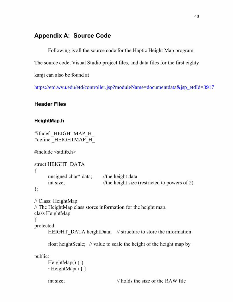
#ifndef _HEIGHTMAP_H_ #define _HEIGHTMAP_H_ #include <stdlib.h> struct HEIGHT_DATA { unsigned char* data; //the height data int size; //the height size (restricted to powers of 2) }; // Class: HeightMap // The HeightMap class stores information for the height map. class HeightMap { protected: HEIGHT_DATA heightData; // structure to store the information float heightScale; // value to scale the height of the height map by public: HeightMap() { } ~HeightMap() { } int size; // holds the size of the RAW file
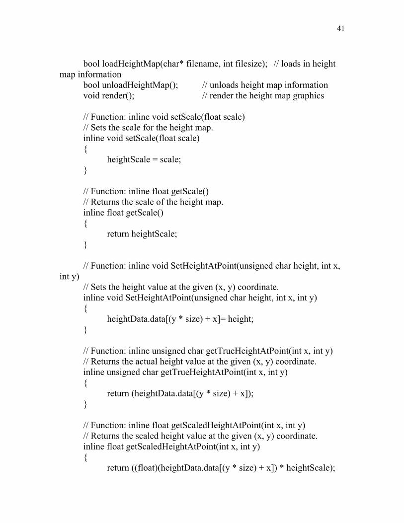
bool loadHeightMap(char* filename, int filesize); // loads in height map information bool unloadHeightMap(); // unloads height map information void render(); // render the height map graphics // Function: inline void setScale(float scale) // Sets the scale for the height map. inline void setScale(float scale) { heightScale = scale; } // Function: inline float getScale() // Returns the scale of the height map. inline float getScale() { return heightScale; } // Function: inline void SetHeightAtPoint(unsigned char height, int x, int y) // Sets the height value at the given (x, y) coordinate. inline void SetHeightAtPoint(unsigned char height, int x, int y) { heightData.data[(y * size) + x]= height; } // Function: inline unsigned char getTrueHeightAtPoint(int x, int y) // Returns the actual height value at the given (x, y) coordinate. inline unsigned char getTrueHeightAtPoint(int x, int y) { return (heightData.data[(y * size) + x]); } // Function: inline float getScaledHeightAtPoint(int x, int y) // Returns the scaled height value at the given (x, y) coordinate. inline float getScaledHeightAtPoint(int x, int y) { return ((float)(heightData.data[(y * size) + x]) * heightScale);
42
} }; #endif // _HEIGHTMAP_H_
Point.h
#ifndef _POINT_H_ #define _POINT_H_ // Class: Point // This class holds information for individual points for the strokes. class Point { private: int x; // x coordinate int y; // y coordinate public: Point() { x = y = 0; } // Constructor Point(int inX, int inY) { x = inX; y = inY; } // Constructor - sets (x, y) coordinate int X() { return x; } // Returns value of x int Y() { return y; } // Returns value of y void X(int temp) { x = temp; } // Sets value of x void Y(int temp) { y = temp; } // Sets value of y }; #endif // _POINT_H_
using namespace std; // Class: Stroke // Holds the information for one kanji stroke. class Stroke { private: vector<Point> points; // vector to store the individual points of the stroke float scaleFactor; // amount to scale the stroke when it is rendered public: Stroke(float scale) { scaleFactor = scale; } // Constructor void render(bool arrows); // Renders the stroke void addPoint(Point* temp); // Adds a point at the end of the stroke Point pointAt(int num) { return points[num]; } // Returns the stroke at num int size() { return points.size(); } // Returns the number of points in the vector }; #endif // _STROKE_H_
StrokeOrder.h
#ifndef _STROKEORDER_H_ #define _STROKEORDER_H_ #include "Stroke.h" #include <Vector> using namespace std; // Class: StrokeOrder // Stores all the strokes of the stroke order for a given kanji. class StrokeOrder { private:
44
vector<Stroke> strokes; // vector to hold the strokes float scaleFactor; // amount to scale the strokes when they are rendered public: StrokeOrder(float scale) { scaleFactor = scale; } // Constructor void setScale(float scale) { scaleFactor = scale; } // Sets the scale factor void render(int num, bool arrows); // Renders the stroke order void addStroke(Stroke* temp); // Adds a stroke to the end of the stroke order int totalStrokes(void) { return strokes.size(); } // Returns the total number of strokes in the stroke order void saveFile(char* filename); // Saves the stroke order to a file void loadFile(char* filename); // Loads in the stroke order from a file }; #endif // _STROKEORDER_H_
// This function loads in information for the height map. // It reports an error if the file does not load properly. bool HeightMap::loadHeightMap(char* filename, int filesize) { FILE* tempFile; // if data is currently loaded, unload that information if(heightData.data) this->unloadHeightMap(); // open the RAW data file for reading tempFile = fopen(filename, "rb"); // report an error if the file is not loaded if(tempFile == NULL) { // bad filename fprintf(stdout, "An error occured while loading height map information.\n"); return false; } // create an array to hold the height data heightData.data = new unsigned char [(filesize * filesize)]; // report an error if memory is not allocated if(heightData.data == NULL) { //failed to allocate memory fprintf(stdout, "Could not allocate memory to load the file."); return false; } // read in the height map data fread(heightData.data, 1, (filesize * filesize), tempFile); // close the file fclose(tempFile); // set the m_iSize data this->size = filesize;
46
// report that the file has been read successfully fprintf(stdout, "Height map data has been loaded.\n"); return true; } // Function: bool HeightMap::unloadHeightMap() // This function unloads the height map from memory. bool HeightMap::unloadHeightMap() { // if there is data then unload it if(heightData.data) { // delete the data delete[] heightData.data; // reset the size size= 0; } // report that the height map has been unloaded fprintf(stdout, "Height map data unloaded."); return true; } // Function: void HeightMap::render() // This function renders the height map in both the graphics and the haptics. void HeightMap::render() { unsigned char color; // used to set the color value for vertices int Y; // counter to loop through the Y values of the height map int X; // counter to loop through the X values of the height map // enable culling to get rid of unnecessary polygons glEnable(GL_CULL_FACE); // loop through Y values for (Y = 0; Y < (size - 1); Y++) { // begin drawing a triangle strip for this Y value
47
glBegin(GL_TRIANGLE_STRIP); // loop through X values for(X=0; X<size-1; X++) { // set the color based on the height color = this->getTrueHeightAtPoint(X, Y); glColor3ub(color, color, color); // render the point glVertex3f((float)X, (float)(size - Y), this->getScaledHeightAtPoint(X, Y)); // set the color based on the height color= this->getTrueHeightAtPoint(X, Y+1); glColor3ub(color, color, color); // render the point glVertex3f((float)X, (float)(size - (Y+1)), this->getScaledHeightAtPoint(X, Y+1)); } // end the triangle strip glEnd( ); // GL_TRIANGLE_STRIP } }
void idle(void); void heightMapTransform(); void drawSceneGraphics(); void drawSceneHaptics(); void drawCursor(); void updateWorkspace(); void exitHandler(void); void renderStroke(); void keyboard(unsigned char key, int x, int y); // Function: void init() // Initializes the graphic and haptic context to prepare for display. void init() { initGL(); initHL(); } // Function: void initGL() // Initializes states for the graphics engine. void initGL() { glClearColor(0.0f, 0.0f, 1.0f, 0.0f); // set the background color to blue glDisable(GL_TEXTURE_2D); // disable two dimensional textures glDisable(GL_LIGHTING); // disable lighting glDisable(GL_BLEND); // disable blending glEnable(GL_DEPTH_TEST); // enable depth testing glCullFace(GL_BACK); // set culling for back faces glEnable(GL_CULL_FACE); // enable culling glShadeModel(GL_SMOOTH); // set smooth shading glClearDepth(1.0); // depth buffer setup glDepthFunc(GL_LEQUAL); // type of depth testing glHint(GL_PERSPECTIVE_CORRECTION_HINT, GL_NICEST); // the nicest perspective look } // Function: void initHL()
50
// Initializes states for the haptics engine. void initHL() { HDErrorInfo error; // Initialize the device and report any errors. // Exit if there is an error with the device. hHD = hdInitDevice(HD_DEFAULT_DEVICE); if (HD_DEVICE_ERROR(error = hdGetError())) { hduPrintError(stderr, &error, "Failed to initialize haptic device"); fprintf(stderr, "Press any key to exit"); getchar(); exit(-1); } hHLRC = hlCreateContext(hHD); hlMakeCurrent(hHLRC); // Enable optimization of the viewing parameters when rendering // geometry for OpenHaptics hlEnable(HL_HAPTIC_CAMERA_VIEW); // generate id's for the shapes heightMapShapeId = hlGenShapes(1); strokeShapeId = hlGenShapes(1); // set the stiffness to use with the device HDdouble kStiffness; hdGetDoublev(HD_NOMINAL_MAX_STIFFNESS, &kStiffness); // set the distance at which the device will snap to objects gHapticsSnapDistance = 5.0 / kStiffness; } // Function: void exitHandler() // Deletes references to objects when the program is shut down. void exitHandler() { // delete all the shape IDs
51
hlDeleteShapes(heightMapShapeId, 1); hlDeleteShapes(strokeShapeId, 1); // free haptic context hlMakeCurrent(NULL); if (hHLRC != NULL) { hlDeleteContext(hHLRC); } // free haptic device if (hHD != HD_INVALID_HANDLE) { hdDisableDevice(hHD); } } // Function: void updateWorkspace() // Updates the haptic context when the workspace size changes. void updateWorkspace() { GLdouble modelview[16]; GLdouble projection[16]; GLint viewport[4]; // obtain information about the scene glGetDoublev(GL_MODELVIEW_MATRIX, modelview); glGetDoublev(GL_PROJECTION_MATRIX, projection); glGetIntegerv(GL_VIEWPORT, viewport); // reset the haptic context hlMatrixMode(HL_TOUCHWORKSPACE); hlLoadIdentity(); // fit haptic workspace to view volume hluFitWorkspace(projection); // compute cursor scale gCursorScale = hluScreenToModelScale(modelview, projection, viewport);
52
gCursorScale *= CURSOR_SIZE_PIXELS; } // Function: void reshape(int width, int height) // Handles changes to the graphic and haptic context when the window is resized. // Borrowed from examples that came from SensAble. void reshape(int width, int height) { static const double kPI = 3.1415926535897932384626433832795; static const double kFovY = 40; double nearDist, farDist, aspect; glViewport(0, 0, width, height); /* Compute the viewing parameters based on a fixed fov and viewing * a canonical box centered at the origin */ nearDist = 1.0 / tan((kFovY / 2.0) * kPI / 180.0); farDist = nearDist + 2.0; aspect = (double) width / height; glMatrixMode(GL_PROJECTION); glLoadIdentity(); gluPerspective(kFovY, aspect, nearDist, farDist); /* Place the camera down the Z axis looking at the origin */ glMatrixMode(GL_MODELVIEW); glLoadIdentity(); gluLookAt(0, 0, nearDist + 1.0, 0, 0, 0, 0, 1, 0); updateWorkspace(); } // Function: void display() // Is called during the display loop. Contains all calls to objects // that should be displayed.
53
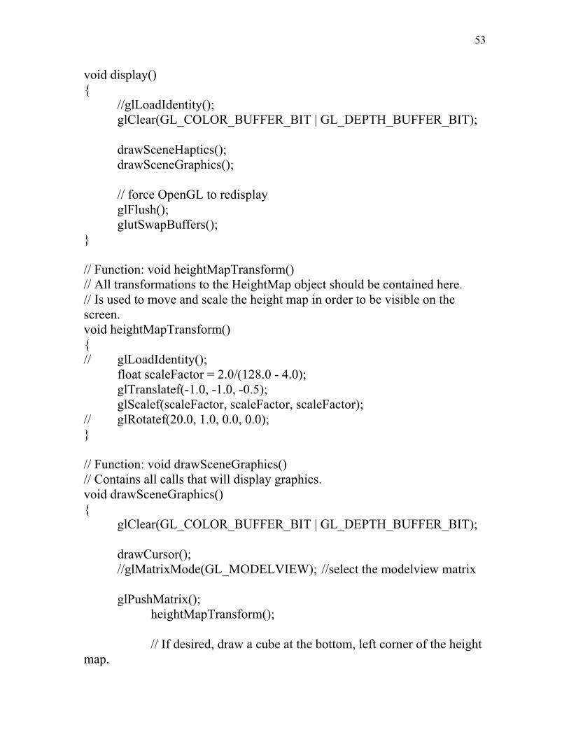
void display() { //glLoadIdentity(); glClear(GL_COLOR_BUFFER_BIT | GL_DEPTH_BUFFER_BIT); drawSceneHaptics(); drawSceneGraphics(); // force OpenGL to redisplay glFlush(); glutSwapBuffers(); } // Function: void heightMapTransform() // All transformations to the HeightMap object should be contained here. // Is used to move and scale the height map in order to be visible on the screen. void heightMapTransform() { // glLoadIdentity(); float scaleFactor = 2.0/(128.0 - 4.0); glTranslatef(-1.0, -1.0, -0.5); glScalef(scaleFactor, scaleFactor, scaleFactor); // glRotatef(20.0, 1.0, 0.0, 0.0); } // Function: void drawSceneGraphics() // Contains all calls that will display graphics. void drawSceneGraphics() { glClear(GL_COLOR_BUFFER_BIT | GL_DEPTH_BUFFER_BIT); drawCursor(); //glMatrixMode(GL_MODELVIEW); //select the modelview matrix glPushMatrix(); heightMapTransform(); // If desired, draw a cube at the bottom, left corner of the height map.
54
if (drawCube) { glColor3f(0.0, 1.0, 0.0); glutSolidCube(1.0); } // render the height map hMap.render(); // if strokes are turned on, draw the current stroke if (drawStroke) strokeOrder.render(currentStroke, true); glPopMatrix(); } // Function: void drawSceneHaptics() // Contains all calls that will display haptics. void drawSceneHaptics() { // begin haptic frame - required to draw in the haptic context hlBeginFrame(); glClear(GL_COLOR_BUFFER_BIT | GL_DEPTH_BUFFER_BIT); glPushMatrix(); // set up parameters for the height map heightMapTransform(); hlBeginShape(HL_SHAPE_FEEDBACK_BUFFER, heightMapShapeId); // make the height map so it can be touched but doesn't force the cursor to snap to it hlTouchModel(HL_CONTACT); // set up physical forces for the height map hlMaterialf(HL_FRONT_AND_BACK, HL_STIFFNESS, 0.8); hlMaterialf(HL_FRONT, HL_STATIC_FRICTION, 0); hlMaterialf(HL_FRONT, HL_DYNAMIC_FRICTION, 0); // If desired, draw a cube at the bottom, left corner of the height map.
55
if (drawCube) { glColor3f(0.0, 1.0, 0.0); glutSolidCube(1.0); } // render the height map hMap.render(); hlEndShape(); // heightMapShapeId // if strokes are turned on, draw the current stroke if (drawStroke) { // set up parameters for the stroke order hlBeginShape(HL_SHAPE_FEEDBACK_BUFFER, strokeShapeId); // only render the strokes in the haptics if we want to snap to them if (forceSnap) { // set the strokes so you are forced to follow along the lines hlTouchModel(HL_CONSTRAINT); hlTouchModelf(HL_SNAP_DISTANCE, gHapticsSnapDistance); // set up physical forces for the stroke order hlMaterialf(HL_FRONT, HL_STIFFNESS, 0.2); hlMaterialf(HL_FRONT, HL_STATIC_FRICTION, 0); hlMaterialf(HL_FRONT, HL_DYNAMIC_FRICTION, 0); // render the stroke order without arrowheads strokeOrder.render(currentStroke, false); } hlEndShape(); // strokeShapeId } glPopMatrix(); // end the haptic frame
56
hlEndFrame(); } // Function: void idle(void) // This function is called whenever the system is not performing calculations. // This function handles refreshing the graphics and haptics. void idle(void) { glutPostRedisplay(); //display(); } // Function: void createStroke(char* filename) // This function is used to create a stroke order for the stroke. void createStroke(char* filename) { // first stroke Stroke* temp = new Stroke(hMap.getScale()); Point* start = new Point(50, 21); // Point* middle = new Point(40, 39); Point* end = new Point(19, 53); temp->addPoint(start); // temp->addPoint(middle); temp->addPoint(end); strokeOrder.addStroke(temp); // second stroke Stroke* temp2 = new Stroke(hMap.getScale()); Point* startb = new Point(40, 40); // Point* middleb1 = new Point(79, 37); // Point* middleb2 = new Point(87, 110); // Point* middleb3 = new Point(89, 95); Point* endb = new Point(38, 99); temp2->addPoint(startb); // temp2->addPoint(middleb1); // temp2->addPoint(middleb2); // temp2->addPoint(middleb3); temp2->addPoint(endb); strokeOrder.addStroke(temp2);
57
// third stroke Stroke* temp3 = new Stroke(hMap.getScale()); Point* startc = new Point(63, 32); // Point* middlec1 = new Point(58 , 63); Point* endc = new Point(109, 31); temp3->addPoint(startc); // temp3->addPoint(middlec1); temp3->addPoint(endc); strokeOrder.addStroke(temp3); // forth stroke Stroke* temp4 = new Stroke(hMap.getScale()); Point* startd = new Point(85, 20); // Point* middled1 = new Point(86, 68); Point* endd = new Point(86, 97); temp4->addPoint(startd); // temp4->addPoint(middled1); temp4->addPoint(endd); strokeOrder.addStroke(temp4); // fifth stroke Stroke* temp5 = new Stroke(hMap.getScale()); Point* starte = new Point(83, 41); Point* middlee1 = new Point(72, 59); Point* ende = new Point(57, 74); temp5->addPoint(starte); temp5->addPoint(middlee1); temp5->addPoint(ende); strokeOrder.addStroke(temp5); // sixth stroke Stroke* temp6 = new Stroke(hMap.getScale()); Point* startf = new Point(90, 41); Point* middlef1 = new Point(103, 58); Point* endf = new Point(125, 70); temp6->addPoint(startf); temp6->addPoint(middlef1); temp6->addPoint(endf); strokeOrder.addStroke(temp6); /*
58
// seventh stroke Stroke* temp7 = new Stroke(hMap.getScale()); Point* startg = new Point(80, 91); Point* endg = new Point(68, 107); temp7->addPoint(startg); temp7->addPoint(endg); strokeOrder.addStroke(temp7); // eighth stroke Stroke* temp8 = new Stroke(hMap.getScale()); Point* starth = new Point(39, 110); Point* endh = new Point(88, 108); temp8->addPoint(starth); temp8->addPoint(endh); strokeOrder.addStroke(temp8); */ strokeOrder.saveFile(filename); } int main(int argc, char *argv[]) { // information about the files to load in char* file = "data\\0018.RAW"; char* strokefile = "data\\0018.str"; // load in the height map and set up information for it hMap.loadHeightMap(file, 128); hMap.setScale(0.05f); // set up the stroke order based on the scale of the height map strokeOrder.setScale(hMap.getScale()); // call createStroke() if there is no stroke data // createStroke(strokefile); // load stroke order data if it exists strokeOrder.loadFile(strokefile); // set up glut to handle the window, display, and keyboard glutInit(&argc,argv);
59
glutInitWindowSize(600,600); glutInitDisplayMode(GLUT_DOUBLE | GLUT_RGB | GLUT_DEPTH); glutCreateWindow("Haptic Height Map"); glutReshapeFunc(reshape); glutDisplayFunc(display); glutIdleFunc(idle); glutKeyboardFunc(keyboard); // call the initialize function init(); // go into the main display loop glutMainLoop(); return 0; } // Function: void keyboard(unsigned char key, int x, int y) // This function handles when the user pushes a key on the keyboard. void keyboard(unsigned char key, int x, int y) { switch (key) { // move to the next stroke case '.': // if on the last stroke, change to 0 and show all strokes if (currentStroke == strokeOrder.totalStrokes()) currentStroke = 0; // if not on the last stroke go to the next stroke else currentStroke++; break; // move to the previous stroke case ',': // if showing all strokes, change to the last stroke if (currentStroke == 0) currentStroke = strokeOrder.totalStrokes(); // if not showing all strokes, show the previous stroke else currentStroke--;
60
break; // toggle whether to snap to the strokes case 'f': case 'F': forceSnap = !forceSnap; break; // exit the program case 'q': case 'Q': exit(0); break; // toggle whether to show the strokes case 's': case 'S': drawStroke = !drawStroke; break; } } // Function: void drawCursor() // This function draws a cursor at the point where the haptic device is. // This was borrowed from an example from SensAble. void drawCursor() { static const double kCursorRadius = 0.5; static const double kCursorHeight = 1.5; static const int kCursorTess = 15; HLdouble proxyxform[16]; GLUquadricObj *qobj = 0; glPushAttrib(GL_CURRENT_BIT | GL_ENABLE_BIT | GL_LIGHTING_BIT); glPushMatrix(); if (!gCursorDisplayList) { gCursorDisplayList = glGenLists(1); glNewList(gCursorDisplayList, GL_COMPILE); qobj = gluNewQuadric();
61
gluCylinder(qobj, 0.0, kCursorRadius, kCursorHeight, kCursorTess, kCursorTess); glTranslated(0.0, 0.0, kCursorHeight); gluCylinder(qobj, kCursorRadius, 0.0, kCursorHeight / 5.0, kCursorTess, kCursorTess); gluDeleteQuadric(qobj); glEndList(); } /* Get the proxy transform in world coordinates */ hlGetDoublev(HL_PROXY_TRANSFORM, proxyxform); glMultMatrixd(proxyxform); /* Apply the local cursor scale factor. */ glScaled(gCursorScale, gCursorScale, gCursorScale); glDisable(GL_LIGHTING); glEnable(GL_COLOR_MATERIAL); glColor3f(0.0, 1.0, 0.0); glCallList(gCursorDisplayList); glPopMatrix(); glPopAttrib(); }
#include "Stroke.h" // Function: void Stroke::render(bool arrows) // This function renders the stroke as an arrow. // If arrows is true, heads are drawn on the arrows. void Stroke::render(bool arrows) { // set up the OpenGL settings for drawing the lines glLineWidth(2.0); glDisable(GL_LIGHTING); glColor3f(1.0, 0.0, 0.0); // begin drawing the lines glBegin(GL_LINE_STRIP); // draw the first point glVertex3f(points[0].X(), (128 - points[0].Y()), ((256 + 1) * scaleFactor)); float xfac, yfac; // the part of the vector in the x and y directions float length; // length between two points in the line float tempx, tempy; // used to create the points for the arrowheads // loop through the rest of the points in the line for(int index = 1; index < points.size(); index++) { // draw the point glVertex3f(points[index].X(), (128 - points[index].Y()), ((256 + 1) * scaleFactor)); // if arrowheads are desired, draw the arrowheads if (arrows) { // compute a vector from the point to the previous point xfac = points[index].X() - points[(index - 1)].X(); yfac = points[index].Y() - points[(index - 1)].Y(); length = sqrt(xfac * xfac + yfac * yfac); // normalize the vector
63
xfac = (xfac / length) * 5; yfac = (yfac / length) * 5; float angle = 35.0; // the angle to rotate the points to make the heads // rotate the normalized vector tempx = ((xfac * cos(angle)) - (yfac * sin(angle))) + points[index].X(); tempy = ((xfac * sin(angle)) + (yfac * cos(angle))) + points[index].Y(); // create the first point of the arrowhead glVertex3f(tempx, (128 - tempy), ((256 + 1) * scaleFactor)); // rotate the normalized vector in the other direction tempx = ((xfac * cos(-angle)) - (yfac * sin(-angle))) + points[index].X(); tempy = ((xfac * sin(-angle)) + (yfac * cos(-angle))) + points[index].Y(); // create the second point of the arrowhead glVertex3f(tempx, (128 - tempy), ((256 + 1) * scaleFactor)); // go back to the original point so it can go on to // the next point in the stroke glVertex3f(points[index].X(), (128 - points[index].Y()), ((256 + 1) * scaleFactor)); } } // end the line strip glEnd(); // GL_LINE_STRIP } // Function: void Stroke::addPoint(Point* temp) // This function adds a point to the vector at the end of the stroke.
#include "StrokeOrder.h" #include <fstream> #include <stdio.h> #include <stdlib.h> // Function: void StrokeOrder::render(int num, bool arrows) // This function renders the strokes in the stroke order. void StrokeOrder::render(int num, bool arrows) { // if the number is greater than the total number of strokes // then set it to 0 to render all strokes if (num > this->strokes.size()) num = 0; // render all the strokes if the number is 0 if (num == 0) { for (int i = 0; i < strokes.size(); i++) { strokes[i].render(arrows); } } // render only one stroke if the number is a stroke else { strokes[num - 1].render(arrows); } } // Function: void StrokeOrder::addStroke(Stroke* temp) // This function addes a stroke at the end of the vector of strokes. void StrokeOrder::addStroke(Stroke* temp) {
65
strokes.push_back(*temp); } // Function: void StrokeOrder::saveFile(char* filename) // This function saves the stroke order out to the specified file. void StrokeOrder::saveFile(char* filename) { // open an output stream for writing in binary format ofstream fout(filename, ios::binary); // report an error if the file could not be created if (!fout) { fprintf(stdout, "Unable to open stroke order file.\nUnable to save stroke order information.\n"); } // first write the total number of strokes // this is used to know how many strokes there are when the file is loaded int totalStrokes = strokes.size(); fout.write((char*) &totalStrokes, sizeof(int)); // now write out all the strokes for (int i = 0; i < totalStrokes; i++) { // write the total number of points in the strokes // this is used to know how many points there are when the file is loaded int totalPoints = strokes[i].size(); fout.write((char*) &totalPoints, sizeof(int)); // write the (x, y) coordinate for each point in the stroke order Point temp; for (int j = 0; j < totalPoints; j++) { int x = strokes[i].pointAt(j).X(); int y = strokes[i].pointAt(j).Y(); fout.write((char*) &x, sizeof(int)); fout.write((char*) &y, sizeof(int));
66
} } // close the file fout.close(); } // Function: void StrokeOrder::loadFile(char* filename) // This function is used to load information from a file into the stroke order. void StrokeOrder::loadFile(char* filename) { // open the file for binary data reading ifstream fin(filename, ios::binary); // if the file does not exist, report an error if (!fin) { fprintf(stdout, "Unable to open stroke order file.\nUnable to load stroke order information.\n"); } // read in the total number of strokes contained in the file int totalStrokes; fin.read((char*) &totalStrokes, sizeof(int)); // loop through the strokes and read in all the points for each stroke for (int i = 0; i < totalStrokes; i++) { // read in the total number of points for the stroke Stroke* tempStroke = new Stroke(this->scaleFactor); int totalPoints; fin.read((char*) &totalPoints, sizeof(int)); // read in the (x, y) coordinates of each point and add the point to the stroke for (int j = 0; j < totalPoints; j++) { int x, y; fin.read((char*) &x, sizeof(int)); fin.read((char*) &y, sizeof(int));
67
Point* tempPoint = new Point(x, y); tempStroke->addPoint(tempPoint); } // add the stroke to the stroke order this->addStroke(tempStroke); } }