Registration made easy – standalone orthopedic navigation with HoloLens Florentin Liebmann 1,2 , Simon Roner 1,3 , Marco von Atzigen 1,2 , Florian Wanivenhaus 3 , Caroline Neuhaus , Jos´ e Spirig 3 , Davide Scaramuzza 5,6 , Reto Sutter 7 , Jess Snedeker 2,3 , Mazda Farshad 3 , and Philipp F ¨ urnstahl 1 1 Computer Assisted Research & Development, Balgrist University Hospital 2 Laboratory for Orthopaedic Biomechanics, ETH Zurich 3 Orthopaedic Department, Balgrist University Hospital, University of Zurich 5 Department of Informatics, University of Zurich 6 Department of Neuroinformatics, University of Zurich and ETH Zurich 7 Radiology Department, Balgrist University Hospital, University of Zurich Abstract In surgical navigation, finding correspondence between preoperative plan and intraoperative anatomy, the so-called registration task, is imperative. One promising approach is to intraoperatively digitize anatomy and register it with the preoperative plan. State-of-the-art commercial naviga- tion systems implement such approaches for pedicle screw placement in spinal fusion surgery. Although these systems improve surgical accuracy, they are not gold standard in clinical practice. Besides economical reasons, this may be due to their difficult integration into clinical workflows and unintuitive navigation feedback. Augmented Reality has the potential to overcome these limitations. Consequently, we propose a surgical navigation approach comprising intra- operative surface digitization for registration and intuitive holographic navigation for pedicle screw placement that runs entirely on the Microsoft HoloLens. Preliminary re- sults from phantom experiments suggest that the method may meet clinical accuracy requirements. 1. Introduction Finding correspondence between preoperative surgical plan and intraoperative anatomy is one of the core tasks in surgical navigation. This process is referred to as reg- istration. Markelj et al.[13] give a good overview on clin- ical imaging modalities and the resulting registration pos- sibilities. Preoperative data are 3D computed tomography (CT) or magnetic resonance images. In orthopedic surgery, common 2D imaging modalities are ultrasound (US), flu- oroscopy or optical images. Cone-beam CT (CBCT), US and reconstruction with optical systems are 3D data sources. Consequently, intraoperative registrations are either 3D/2D or 3D/3D. 3D/3D is further subdivided into image-to-image and image-to-patient (when reconstruction with optical sys- tems is employed). In terms of 3D/2D registration, the most widely used ap- proach involves digitally reconstructed radiographs (DRR), i.e. simulated 2D views generated from preoperative 3D data. The DRR are compared to intraoperative 2D fluoro- scopic images using a similarity measure which can be op- timized in an iterative fashion. However, surgical tools, im- plants and resected soft tissue which are usually not present in preoperative images make this approach challenging [6]. DRR generation is computationally expensive and a bal- ance between robustness and computational cost has to be found [14]. Moreover, a calibrated intraoperative setup is required. Apart from a technical point of view, any intraoperative imaging that implies radiation exposure for patient and OR personnel is considered critically (e.g. [16]). This adversely affects the use of intraoperative fluoroscopy and especially CBCT. 2D and 3D US are radiation-free alternatives. Nev- ertheless, they are not well-suited for open surgery due to their reliance on a transportation medium (e.g. [30]). Summarizing above findings, radiation-free 3D/3D image-to-patient registration can be considered most promising. An exemplary method following this approach is Surface Matching, in which a 3D reconstruction of the visible anatomy is achieved by sampling bone surface with a tracked pointer. It is implemented in state-of-the-art com- mercial navigation systems and is well-known for pedicle arXiv:2001.06209v1 [cs.CV] 17 Jan 2020
Transcript
Registration made easy – standalone orthopedic navigation with HoloLens
Florentin Liebmann1,2, Simon Roner1,3, Marco von Atzigen1,2, Florian Wanivenhaus3, CarolineNeuhaus , Jose Spirig3, Davide Scaramuzza5,6, Reto Sutter7, Jess Snedeker2,3, Mazda Farshad3, and
Philipp Furnstahl1
1 Computer Assisted Research & Development, Balgrist University Hospital2 Laboratory for Orthopaedic Biomechanics, ETH Zurich
3 Orthopaedic Department, Balgrist University Hospital, University of Zurich5 Department of Informatics, University of Zurich
6 Department of Neuroinformatics, University of Zurich and ETH Zurich7 Radiology Department, Balgrist University Hospital, University of Zurich
Abstract
In surgical navigation, finding correspondence betweenpreoperative plan and intraoperative anatomy, the so-calledregistration task, is imperative. One promising approachis to intraoperatively digitize anatomy and register it withthe preoperative plan. State-of-the-art commercial naviga-tion systems implement such approaches for pedicle screwplacement in spinal fusion surgery. Although these systemsimprove surgical accuracy, they are not gold standard inclinical practice. Besides economical reasons, this may bedue to their difficult integration into clinical workflows andunintuitive navigation feedback. Augmented Reality has thepotential to overcome these limitations. Consequently, wepropose a surgical navigation approach comprising intra-operative surface digitization for registration and intuitiveholographic navigation for pedicle screw placement thatruns entirely on the Microsoft HoloLens. Preliminary re-sults from phantom experiments suggest that the methodmay meet clinical accuracy requirements.
1. Introduction
Finding correspondence between preoperative surgicalplan and intraoperative anatomy is one of the core tasksin surgical navigation. This process is referred to as reg-istration. Markelj et al. [13] give a good overview on clin-ical imaging modalities and the resulting registration pos-sibilities. Preoperative data are 3D computed tomography(CT) or magnetic resonance images. In orthopedic surgery,common 2D imaging modalities are ultrasound (US), flu-
oroscopy or optical images. Cone-beam CT (CBCT), USand reconstruction with optical systems are 3D data sources.Consequently, intraoperative registrations are either 3D/2Dor 3D/3D. 3D/3D is further subdivided into image-to-imageand image-to-patient (when reconstruction with optical sys-tems is employed).
In terms of 3D/2D registration, the most widely used ap-proach involves digitally reconstructed radiographs (DRR),i.e. simulated 2D views generated from preoperative 3Ddata. The DRR are compared to intraoperative 2D fluoro-scopic images using a similarity measure which can be op-timized in an iterative fashion. However, surgical tools, im-plants and resected soft tissue which are usually not presentin preoperative images make this approach challenging [6].DRR generation is computationally expensive and a bal-ance between robustness and computational cost has to befound [14]. Moreover, a calibrated intraoperative setup isrequired.
Apart from a technical point of view, any intraoperativeimaging that implies radiation exposure for patient and ORpersonnel is considered critically (e.g. [16]). This adverselyaffects the use of intraoperative fluoroscopy and especiallyCBCT. 2D and 3D US are radiation-free alternatives. Nev-ertheless, they are not well-suited for open surgery due totheir reliance on a transportation medium (e.g. [30]).
Summarizing above findings, radiation-free 3D/3Dimage-to-patient registration can be considered mostpromising. An exemplary method following this approachis Surface Matching, in which a 3D reconstruction of thevisible anatomy is achieved by sampling bone surface witha tracked pointer. It is implemented in state-of-the-art com-mercial navigation systems and is well-known for pedicle
arX
iv:2
001.
0620
9v1
[cs
.CV
] 1
7 Ja
n 20
20
screw placement in spinal fusion surgery [23, 18, 5]. Al-though such systems increase accuracy, they are not estab-lished as the clinical gold standard [1]. Besides high costsfor acquisition and maintenance, the main reason may bethat they cannot be integrated into clinical practice with-out effort and hinder seamless workflows (e.g. line of sightissues) [27]. Furthermore, anatomical 3D models and navi-gation feedback are not superimposed in situ, but visualizedon peripheral 2D monitors which makes it hard to compre-hend the underlying 3D space in an intuitive way [22].
Augmented Reality (AR) has the potential to overcomethese limitations. It has been considered interesting formedical applications for more than a decade [25, 17], butonly recent technological advancement allows for the de-velopment of computationally powerful, off-the-shelf opti-cal see-through head mounted-displays [21]. We proposeda radiation-free surgical navigation approach comprising in-traoperative manual surface digitization for registration andintuitive holographic navigation for pedicle screw place-ment that runs entirely on the Microsoft HoloLens [12]. Themethodology of our approach and a pre-clinical evaluationare presented together with another in-house HoloLens ap-plication related to spinal fusion surgery [29].
2. MethodsThe presented method consists of two main components:
intraoperative registration and surgical navigation. Bothrely on 6DoF marker tracking.
2.1. Marker tracking and pose estimation
Marker tracking was implemented employing the twofront-facing of the four environment tracking cameras thatare accessible via Research Mode [15]. Commercial, ster-ile fiducial markers (Clear Guide Medical, Baltimore MD,USA) were used. Their patterns originate from the AprilT-ags library [19, 28]. We refer to the official terminologyof the HoloLens coordinate systems to describe the pro-cess: App-specified Coordinate System (ASCS), CameraCoordinate System (CCS), 3D Camera View Space (CVS)and 2D Camera Projection Space (CPS). CVS and CPSof the left and right camera are termed CVSL/CVSR andCPSL/CPSR, respectively. An exemplary transformationfrom CPS to CVS is denoted as TCV S
CPS .For each pair of images (left and right) with a detectable
marker, its pose is derived as follows. Initial estimate val-ues CL
1 , . . . , CL4 and CR
1 , . . . , CR4 of the four corners of the
marker are detected in both images using the ArUco library[7, 8, 24]. Due to the low resolution (480 × 640 pixels) ofthe environmental cameras, each Ci is passed to a dedicatedKalman filter with a constant velocity model [11, 3].
The filtered corner estimates are transformed to CPS andextended by one dimension (unit plane: z = 1) such thatthey can be expressed in CVS and further transformed to
CCS. To perform triangulation, directional vectors ~dLi and~dRi between each TCCS
CPSLCLi and TCCS
CPSRCRi and their re-
spective camera centers are formed. Triangulation can becompleted by finding the closest point min(~dLi ,
~dRi ) be-tween each pair of directional vectors.
Given the new 3D estimates min(~dLi ,~dRi ), the 6DoF
marker pose is derived by incorporating prior knowledgeabout the marker geometry. As the true 3D position gtiof each corner point with respect to the marker centeris known, the pose estimation problem can be reducedto finding a rigid transformation between the point pairsmin(~dLi ,
~dRi ) and gti in a least-square sense. The transfor-mation results from applying the absolute orientation [10].
2.2. Registration
The idea of our surface digitization approach is toestablish correspondence between pre- and intraoperativeanatomy without using intraoperative imaging.
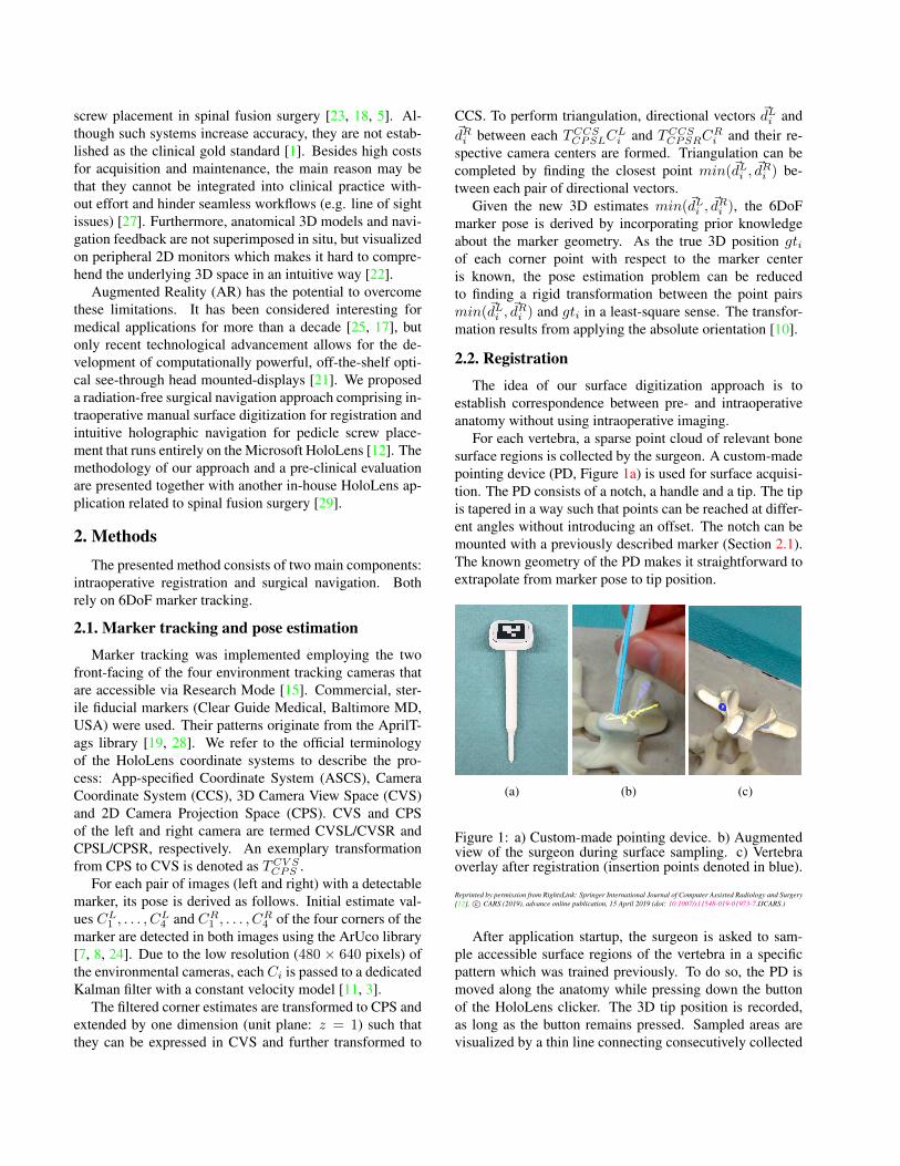
For each vertebra, a sparse point cloud of relevant bonesurface regions is collected by the surgeon. A custom-madepointing device (PD, Figure 1a) is used for surface acquisi-tion. The PD consists of a notch, a handle and a tip. The tipis tapered in a way such that points can be reached at differ-ent angles without introducing an offset. The notch can bemounted with a previously described marker (Section 2.1).The known geometry of the PD makes it straightforward toextrapolate from marker pose to tip position.
(a) (b) (c)
Figure 1: a) Custom-made pointing device. b) Augmentedview of the surgeon during surface sampling. c) Vertebraoverlay after registration (insertion points denoted in blue).
After application startup, the surgeon is asked to sam-ple accessible surface regions of the vertebra in a specificpattern which was trained previously. To do so, the PD ismoved along the anatomy while pressing down the buttonof the HoloLens clicker. The 3D tip position is recorded,as long as the button remains pressed. Sampled areas arevisualized by a thin line connecting consecutively collected
points (Figure 1b). Once the button is released, a voice com-mand can be used to indicate whether the just collected re-gion should be saved (“save”) or discarded (“delete”). Onlythe saved points are used for registration. When sufficientpoints have been sampled, a double click starts registration.
The intraoperatively collected point cloud pcintra is reg-istered to the point cloud pcpre representing the points ofthe 3D model of the preoperative vertebra. In a preprocess-ing step, pcpre is trimmed by removing points which candefinitely not be reached with the PD in a surgery.
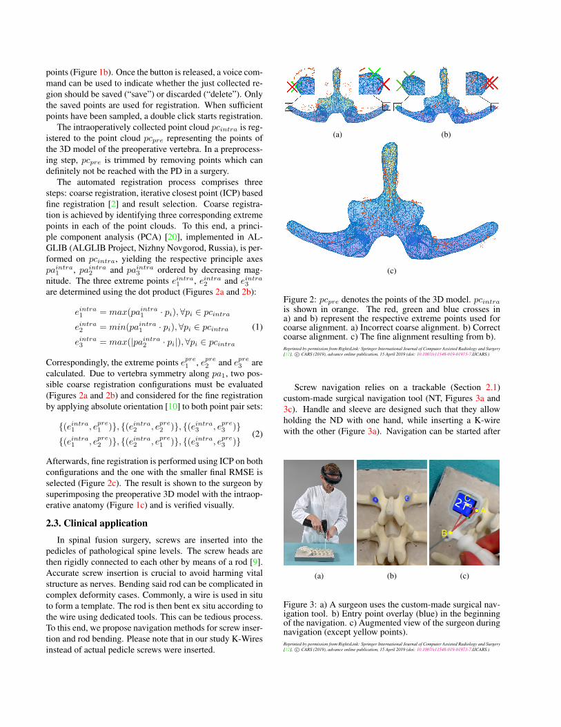
The automated registration process comprises threesteps: coarse registration, iterative closest point (ICP) basedfine registration [2] and result selection. Coarse registra-tion is achieved by identifying three corresponding extremepoints in each of the point clouds. To this end, a princi-ple component analysis (PCA) [20], implemented in AL-GLIB (ALGLIB Project, Nizhny Novgorod, Russia), is per-formed on pcintra, yielding the respective principle axespaintra1 , paintra2 and paintra3 ordered by decreasing mag-nitude. The three extreme points eintra1 , eintra2 and eintra3
are determined using the dot product (Figures 2a and 2b):
eintra1 = max(paintra1 · pi),∀pi ∈ pcintra
eintra2 = min(paintra1 · pi),∀pi ∈ pcintra
eintra3 = max(|paintra2 · pi|),∀pi ∈ pcintra
(1)
Correspondingly, the extreme points epre1 , epre2 and epre3 arecalculated. Due to vertebra symmetry along pa1, two pos-sible coarse registration configurations must be evaluated(Figures 2a and 2b) and considered for the fine registrationby applying absolute orientation [10] to both point pair sets:
Afterwards, fine registration is performed using ICP on bothconfigurations and the one with the smaller final RMSE isselected (Figure 2c). The result is shown to the surgeon bysuperimposing the preoperative 3D model with the intraop-erative anatomy (Figure 1c) and is verified visually.
2.3. Clinical application
In spinal fusion surgery, screws are inserted into thepedicles of pathological spine levels. The screw heads arethen rigidly connected to each other by means of a rod [9].Accurate screw insertion is crucial to avoid harming vitalstructure as nerves. Bending said rod can be complicated incomplex deformity cases. Commonly, a wire is used in situto form a template. The rod is then bent ex situ according tothe wire using dedicated tools. This can be tedious process.To this end, we propose navigation methods for screw inser-tion and rod bending. Please note that in our study K-Wiresinstead of actual pedicle screws were inserted.
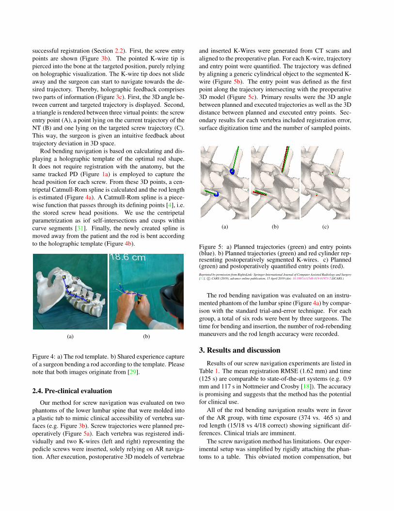
Screw navigation relies on a trackable (Section 2.1)custom-made surgical navigation tool (NT, Figures 3a and3c). Handle and sleeve are designed such that they allowholding the ND with one hand, while inserting a K-wirewith the other (Figure 3a). Navigation can be started after
successful registration (Section 2.2). First, the screw entrypoints are shown (Figure 3b). The pointed K-wire tip ispierced into the bone at the targeted position, purely relyingon holographic visualization. The K-wire tip does not slideaway and the surgeon can start to navigate towards the de-sired trajectory. Thereby, holographic feedback comprisestwo parts of information (Figure 3c). First, the 3D angle be-tween current and targeted trajectory is displayed. Second,a triangle is rendered between three virtual points: the screwentry point (A), a point lying on the current trajectory of theNT (B) and one lying on the targeted screw trajectory (C).This way, the surgeon is given an intuitive feedback abouttrajectory deviation in 3D space.
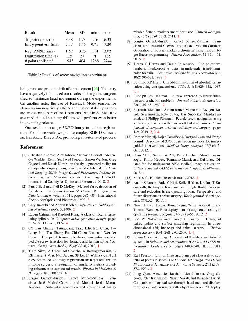
Rod bending navigation is based on calculating and dis-playing a holographic template of the optimal rod shape.It does not require registration with the anatomy, but thesame tracked PD (Figure 1a) is employed to capture thehead position for each screw. From these 3D points, a cen-tripetal Catmull-Rom spline is calculated and the rod lengthis estimated (Figure 4a). A Catmull-Rom spline is a piece-wise function that passes through its defining points [4], i.e.the stored screw head positions. We use the centripetalparametrization as iof self-intersections and cusps withincurve segments [31]. Finally, the newly created spline ismoved away from the patient and the rod is bent accordingto the holographic template (Figure 4b).
(a) (b)
Figure 4: a) The rod template. b) Shared experience captureof a surgeon bending a rod according to the template. Pleasenote that both images originate from [29].
2.4. Pre-clinical evaluation
Our method for screw navigation was evaluated on twophantoms of the lower lumbar spine that were molded intoa plastic tub to mimic clinical accessibility of vertebra sur-faces (e.g. Figure 3b). Screw trajectories were planned pre-operatively (Figure 5a). Each vertebra was registered indi-vidually and two K-wires (left and right) representing thepedicle screws were inserted, solely relying on AR naviga-tion. After execution, postoperative 3D models of vertebrae
and inserted K-Wires were generated from CT scans andaligned to the preoperative plan. For each K-wire, trajectoryand entry point were quantified. The trajectory was definedby aligning a generic cylindrical object to the segmented K-wire (Figure 5b). The entry point was defined as the firstpoint along the trajectory intersecting with the preoperative3D model (Figure 5c). Primary results were the 3D anglebetween planned and executed trajectories as well as the 3Ddistance between planned and executed entry points. Sec-ondary results for each vertebra included registration error,surface digitization time and the number of sampled points.
The rod bending navigation was evaluated on an instru-mented phantom of the lumbar spine (Figure 4a) by compar-ison with the standard trial-and-error technique. For eachgroup, a total of six rods were bent by three surgeons. Thetime for bending and insertion, the number of rod-rebendingmaneuvers and the rod length accuracy were recorded.
3. Results and discussion
Results of our screw navigation experiments are listed inTable 1. The mean registration RMSE (1.62 mm) and time(125 s) are comparable to state-of-the-art systems (e.g. 0.9mm and 117 s in Nottmeier and Crosby [18]). The accuracyis promising and suggests that the method has the potentialfor clinical use.
All of the rod bending navigation results were in favorof the AR group, with time exposure (374 vs. 465 s) androd length (15/18 vs 4/18 correct) showing significant dif-ferences. Clinical trials are imminent.
The screw navigation method has limitations. Our exper-imental setup was simplified by rigidly attaching the phan-toms to a table. This obviated motion compensation, but
Reg. RMSE (mm) 1.62 0.26 1.14 2.02Digitization time (s) 125 27 91 185# points collected 1983 404 1268 2744
Table 1: Results of screw navigation experiments.
holograms are prone to drift after placement [26]. This mayhave negatively influenced our results, although the surgeontried to minimize head movement during the experiments.On another note, the use of Research Mode sensors forstereo vision negatively affects application stability as theyare an essential part of the HoloLens’ built-in SLAM. It isassumed that all such capabilities will perform even betterin upcoming releases.
Our results encourage 3D/3D image-to-patient registra-tion. For future work, we plan to employ RGB-D sources,such as Azure Kinect DK, promoting an automated process.
References[1] Sebastian Andress, Alex Johson, Mathias Unberath, Alexan-
der Winkler, Kevin Yu, Javad Fotouhi, Simon Weidert, GregOsgood, and Nassir Navab. on-the-fly augmented reality fororthopaedic surgery using a multi-modal fiducial. In Med-ical Imaging 2018: Image-Guided Procedures, Robotic In-terventions, and Modeling, volume 10576, page 105760H.International Society for Optics and Photonics, 2018. 2
[2] Paul J Besl and Neil D McKay. Method for registration of3-d shapes. In Sensor Fusion IV: Control Paradigms andData Structures, volume 1611, pages 586–607. InternationalSociety for Optics and Photonics, 1992. 3
[3] Gary Bradski and Adrian Kaehler. Opencv. Dr. Dobbs jour-nal of software tools, 3, 2000. 2
[4] Edwin Catmull and Raphael Rom. A class of local interpo-lating splines. In Computer aided geometric design, pages317–326. Elsevier, 1974. 4
[5] CY Fan Chiang, Tsung-Ting Tsai, Lih-Huei Chen, Po-Liang Lai, Tsai-Sheng Fu, Chi-Chien Niu, and Wen-JerChen. Computed tomography-based navigation-assistedpedicle screw insertion for thoracic and lumbar spine frac-tures. Chang Gung Med J, 35(4):332–8, 2012. 1
[6] T De Silva, A Uneri, MD Ketcha, S Reaungamornrat, GKleinszig, S Vogt, Nafi Aygun, SF Lo, JP Wolinsky, and JHSiewerdsen. 3d–2d image registration for target localizationin spine surgery: investigation of similarity metrics provid-ing robustness to content mismatch. Physics in Medicine &Biology, 61(8):3009, 2016. 1
[7] Sergio Garrido-Jurado, Rafael Munoz-Salinas, Fran-cisco Jose Madrid-Cuevas, and Manuel Jesus Marın-Jimenez. Automatic generation and detection of highly
reliable fiducial markers under occlusion. Pattern Recogni-tion, 47(6):2280–2292, 2014. 2
[8] Sergio Garrido-Jurado, Rafael Munoz-Salinas, Fran-cisco Jose Madrid-Cuevas, and Rafael Medina-Carnicer.Generation of fiducial marker dictionaries using mixed inte-ger linear programming. Pattern Recognition, 51:481–491,2016. 2
[9] Jurgen G Harms and Dezso Jeszenszky. Die posteriore,lumbale, interkorporelle fusion in unilateraler transforami-naler technik. Operative Orthopadie und Traumatologie,10(2):90–102, 1998. 3
[10] Berthold KP Horn. Closed-form solution of absolute orien-tation using unit quaternions. JOSA A, 4(4):629–642, 1987.2, 3
[11] Rudolph Emil Kalman. A new approach to linear filter-ing and prediction problems. Journal of basic Engineering,82(1):35–45, 1960. 2
[12] Florentin Liebmann, Simon Roner, Marco von Atzigen, Da-vide Scaramuzza, Reto Sutter, Jess Snedeker, Mazda Far-shad, and Philipp Furnstahl. Pedicle screw navigation usingsurface digitization on the microsoft hololens. Internationaljournal of computer assisted radiology and surgery, pages1–9, 2019. 2, 3, 4
[13] Primoz Markelj, Dejan Tomazevic, Bostjan Likar, and FranjoPernus. A review of 3d/2d registration methods for image-guided interventions. Medical image analysis, 16(3):642–661, 2012. 1
[14] Shun Miao, Sebastien Piat, Peter Fischer, Ahmet Tuysu-zoglu, Philip Mewes, Tommaso Mansi, and Rui Liao. Di-lated fcn for multi-agent 2d/3d medical image registration.In Thirty-Second AAAI Conference on Artificial Intelligence,2018. 1
[15] Microsoft. Hololens research mode, 2018. 2[16] Ankur S Narain, Fady Y Hijji, Kelly H Yom, Krishna T Ku-
daravalli, Brittany E Haws, and Kern Singh. Radiation expo-sure and reduction in the operating room: Perspectives andfuture directions in spine surgery. World journal of orthope-dics, 8(7):524, 2017. 1
[17] Nassir Navab, Tobias Blum, Lejing Wang, Asli Okur, andThomas Wendler. First deployments of augmented reality inoperating rooms. Computer, 45(7):48–55, 2012. 2
[18] Eric W Nottmeier and Tracey L Crosby. Timing ofpaired points and surface matching registration in three-dimensional (3d) image-guided spinal surgery. ClinicalSpine Surgery, 20(4):268–270, 2007. 1, 4
[19] Edwin Olson. Apriltag: A robust and flexible visual fiducialsystem. In Robotics and Automation (ICRA), 2011 IEEE In-ternational Conference on, pages 3400–3407. IEEE, 2011.2
[20] Karl Pearson. Liii. on lines and planes of closest fit to sys-tems of points in space. The London, Edinburgh, and DublinPhilosophical Magazine and Journal of Science, 2(11):559–572, 1901. 3
[21] Long Qian, Alexander Barthel, Alex Johnson, Greg Os-good, Peter Kazanzides, Nassir Navab, and Bernhard Fuerst.Comparison of optical see-through head-mounted displaysfor surgical interventions with object-anchored 2d-display.
International journal of computer assisted radiology andsurgery, 12(6):901–910, 2017. 2
[22] Long Qian, Mathias Unberath, Kevin Yu, Bernhard Fuerst,Alex Johnson, Nassir Navab, and Greg Osgood. Towardsvirtual monitors for image guided interventions-real-timestreaming to optical see-through head-mounted displays.arXiv preprint arXiv:1710.00808, 2017. 2
[23] Marcus Richter, Balkan Cakir, and Rene Schmidt. Cervi-cal pedicle screws: conventional versus computer-assistedplacement of cannulated screws. Spine, 30(20):2280–2287,2005. 1
[24] Francisco J Romero-Ramirez, Rafael Munoz-Salinas, andRafael Medina-Carnicer. Speeded up detection of squaredfiducial markers. Image and Vision Computing, 2018. 2
[25] Tobias Sielhorst, Marco Feuerstein, and Nassir Navab. Ad-vanced medical displays: A literature review of augmentedreality. Journal of Display Technology, 4(4):451–467, 2008.2
[26] Reid Vassallo, Adam Rankin, Elvis CS Chen, and Terry MPeters. Hologram stability evaluation for microsoft hololens.In Medical Imaging 2017: Image Perception, Observer Per-formance, and Technology Assessment, volume 10136, page1013614. International Society for Optics and Photonics,2017. 5
[28] John Wang and Edwin Olson. Apriltag 2: Efficient and ro-bust fiducial detection. In IROS, pages 4193–4198, 2016. 2
[29] Florian Wanivenhaus, Caroline Neuhaus, Florentin Lieb-mann, Simon Roner, Jose M Spirig, and Mazda Farshad.Augmented reality-assisted rod bending in spinal surgery.The Spine Journal, 19(10):1687–1689, 2019. 2, 4
[30] Charles XB Yan, Benoıt Goulet, Donatella Tampieri, andD Louis Collins. Ultrasound-ct registration of vertebraewithout reconstruction. International journal of computerassisted radiology and surgery, 7(6):901–909, 2012. 1
[31] Cem Yuksel, Scott Schaefer, and John Keyser. On the param-eterization of catmull-rom curves. In 2009 SIAM/ACM JointConference on Geometric and Physical Modeling, pages 47–53. ACM, 2009. 4