Basics of Wireless Propagation
Marco Luise, Giacomo [email protected]
Dip. Ingegneria dell’Informazione, Univ. Pisa, Pisa, Italy
Computer Engineering Electronics and Communications Systems
Ele
ctr
on
ics
an
d C
om
mu
nic
atio
ns
Sy
ste
ms
Co
mp
ute
r En
gin
ee
rin
g
G. Bacci, M. LuiseBasics of Wireless Propagation
2
Dip. Ingegneria dell’Informazione
University of Pisa, Pisa, Italy
Basics of wireless
propagation
Ele
ctr
on
ics
an
d C
om
mu
nic
atio
ns
Sy
ste
ms
Co
mp
ute
r En
gin
ee
rin
g
G. Bacci, M. LuiseBasics of Wireless Propagation
3
Dip. Ingegneria dell’Informazione
University of Pisa, Pisa, Italy
The wireless propagation channel
Basics of wireless propagation
Received contributions at the receiver (uplink):
(e.g., due to
electromagnetic
radiations, electronics
impairments, etc.)
The wireless channel between the transmitter and the receiver fluctuates randomly
for a number of causes
Ele
ctr
on
ics
an
d C
om
mu
nic
atio
ns
Sy
ste
ms
Co
mp
ute
r En
gin
ee
rin
g
G. Bacci, M. LuiseBasics of Wireless Propagation
4
Dip. Ingegneria dell’Informazione
University of Pisa, Pisa, Italy
Free-space propagation
Basics of wireless propagation
If we consider the air as a perfectly uniform medium, the received power
can be expressed as
free-space path loss
where
gain of the transmit antenna
gain of the receive antenna
tx-rx distance
carrier wavelength
However, this model is not accurate to describe the wireless channel experienced
by cellular-communication signals
Ele
ctr
on
ics
an
d C
om
mu
nic
atio
ns
Sy
ste
ms
Co
mp
ute
r En
gin
ee
rin
g
G. Bacci, M. LuiseBasics of Wireless Propagation
5
Dip. Ingegneria dell’Informazione
University of Pisa, Pisa, Italy
Large- and small-scale models (1/2)
Basics of wireless propagation
A better suited propagation model is composed by:
o large-scale models, that predict the average energy
received in a wireless system as a function of the
distance between the transmitter and the receiver
o small-scale models, that account for the
instantaneous variations in the propagation
conditions
Ele
ctr
on
ics
an
d C
om
mu
nic
atio
ns
Sy
ste
ms
Co
mp
ute
r En
gin
ee
rin
g
G. Bacci, M. LuiseBasics of Wireless Propagation
6
Dip. Ingegneria dell’Informazione
University of Pisa, Pisa, Italy
Large- and small-scale models (2/2)
Basics of wireless propagation
Ele
ctr
on
ics
an
d C
om
mu
nic
atio
ns
Sy
ste
ms
Co
mp
ute
r En
gin
ee
rin
g
G. Bacci, M. LuiseBasics of Wireless Propagation
7
Dip. Ingegneria dell’Informazione
University of Pisa, Pisa, Italy
Large-scale fading models (1/3)
Basics of wireless propagation
Average received power as a function of the MS-BTS distance d
Using the Hata and Okumura models,
reference distance
Ele
ctr
on
ics
an
d C
om
mu
nic
atio
ns
Sy
ste
ms
Co
mp
ute
r En
gin
ee
rin
g
G. Bacci, M. LuiseBasics of Wireless Propagation
8
Dip. Ingegneria dell’Informazione
University of Pisa, Pisa, Italy
Large-scale fading models (2/3)
Basics of wireless propagation
Average received power as a function of the MS-BTS distance d
urban scenarios
rural areas
free space
urban scenarios
indoor
Ele
ctr
on
ics
an
d C
om
mu
nic
atio
ns
Sy
ste
ms
Co
mp
ute
r En
gin
ee
rin
g
G. Bacci, M. LuiseBasics of Wireless Propagation
9
Dip. Ingegneria dell’Informazione
University of Pisa, Pisa, Italy
Large-scale fading models (3/3)
Basics of wireless propagation
Average received power as a function of a constant distance d
where
dependent on the
propagation
scenario
given by the Hata-
Okumura model:
Ele
ctr
on
ics
an
d C
om
mu
nic
atio
ns
Sy
ste
ms
Co
mp
ute
r En
gin
ee
rin
g
G. Bacci, M. LuiseBasics of Wireless Propagation
10
Dip. Ingegneria dell’Informazione
University of Pisa, Pisa, Italy
Small-scale fading
Basics of wireless propagation
The propagation laws can be computed using the Maxwell
equations. However, this approach is not useful, due to:
o a large computational complexity, but also
o the need for a valid modelf or different
propagation conditions, also considering
the time variability
We need to identify a practical method to account for
the macroscopic phenomena of wireless propagation
Ele
ctr
on
ics
an
d C
om
mu
nic
atio
ns
Sy
ste
ms
Co
mp
ute
r En
gin
ee
rin
g
G. Bacci, M. LuiseBasics of Wireless Propagation
11
Dip. Ingegneria dell’Informazione
University of Pisa, Pisa, Italy
Wavelengths and frequencies in wireless systems (1/2)
Basics of wireless propagation
Wireless radio spectrum:
Carrier wavelengths:
speed of light,
3108 m/s
carrier
frequency
Ele
ctr
on
ics
an
d C
om
mu
nic
atio
ns
Sy
ste
ms
Co
mp
ute
r En
gin
ee
rin
g
G. Bacci, M. LuiseBasics of Wireless Propagation
12
Dip. Ingegneria dell’Informazione
University of Pisa, Pisa, Italy
Wavelengths and frequencies in wireless systems (2/2)
Basics of wireless propagation
Why are such frequencies particularly attractive?
o larger f0’s yield larger path losses:
o smaller f0’s call for larger antennas (with size comparable with )
o smaller f0’s show favorable conditions for over-the-horizon (OTH)
propagation, thus reducing the potential for frequency reuse
o such f0’s can accommodate large enough channel spacing and
provide room for large user multiplexing
o such f0’s have good indoor propagation
Ele
ctr
on
ics
an
d C
om
mu
nic
atio
ns
Sy
ste
ms
Co
mp
ute
r En
gin
ee
rin
g
G. Bacci, M. LuiseBasics of Wireless Propagation
13
Dip. Ingegneria dell’Informazione
University of Pisa, Pisa, Italy
Multipath propagation
Basics of wireless propagation
In this frequency spectrum, the wireless signal experiences a
multipath propagation: the received signal is a linear combination
of multiple paths
In addition to the direct path (a.k.a.
line of sight (LoS) path), the wireless
signal can propagate due to:
o reflection:
o shadowing:
o scattering:
Ele
ctr
on
ics
an
d C
om
mu
nic
atio
ns
Sy
ste
ms
Co
mp
ute
r En
gin
ee
rin
g
G. Bacci, M. LuiseBasics of Wireless Propagation
14
Dip. Ingegneria dell’Informazione
University of Pisa, Pisa, Italy
Reflection
Basics of wireless propagation
Due to the different propagation lengths, for each path the reflection introduces:
o amplitude attenuation
o group delay
o phase delay
Ele
ctr
on
ics
an
d C
om
mu
nic
atio
ns
Sy
ste
ms
Co
mp
ute
r En
gin
ee
rin
g
G. Bacci, M. LuiseBasics of Wireless Propagation
15
Dip. Ingegneria dell’Informazione
University of Pisa, Pisa, Italy
Shadowing
Basics of wireless propagation
Shadowing introduces additional paths when the transmitter and the
receiver are not in visibility, thus affecting the statistics of the channel
Ele
ctr
on
ics
an
d C
om
mu
nic
atio
ns
Sy
ste
ms
Co
mp
ute
r En
gin
ee
rin
g
G. Bacci, M. LuiseBasics of Wireless Propagation
16
Dip. Ingegneria dell’Informazione
University of Pisa, Pisa, Italy
Scattering
Basics of wireless propagation
Similarly, scattering introduced a disordered reflection of the electro-
magnetic waves, thus impacting on attenuations and phase delays
Ele
ctr
on
ics
an
d C
om
mu
nic
atio
ns
Sy
ste
ms
Co
mp
ute
r En
gin
ee
rin
g
G. Bacci, M. LuiseBasics of Wireless Propagation
17
Dip. Ingegneria dell’Informazione
University of Pisa, Pisa, Italy
Multipath propagation model
Basics of wireless propagation
To sum up, the received signal is a linear combination of a number of
different propagation paths, each having its own attenuation, phase
rotation, and time delay:
: number of propagation paths
: attenuation of the i-th
path
: phase delay of the i-thpath
: time delay of the i-thpath
Ele
ctr
on
ics
an
d C
om
mu
nic
atio
ns
Sy
ste
ms
Co
mp
ute
r En
gin
ee
rin
g
G. Bacci, M. LuiseBasics of Wireless Propagation
18
Dip. Ingegneria dell’Informazione
University of Pisa, Pisa, Italy
(Preliminary) classification of the wireless channel
Basics of wireless propagation
Time domain:
o static (time-invariant): its statistics change very slowly wrt
signaling time
o time-varying: its statistics are a function of time
Frequency domain:
o frequency-flat: its behavior is similar across the frequency
components of the signal
o frequency-selective: each frequency component of the
signal is distorted in a different way by the wireless channel
Ele
ctr
on
ics
an
d C
om
mu
nic
atio
ns
Sy
ste
ms
Co
mp
ute
r En
gin
ee
rin
g
G. Bacci, M. LuiseBasics of Wireless Propagation
19
Dip. Ingegneria dell’Informazione
University of Pisa, Pisa, Italy
Static frequency-selective channels (1/4)
Basics of wireless propagation
For the sake of simplicity, let’s consider the two-ray channel, i.e., N=2:
direct (LoS) path reflected path
A static channel means: the random processes , , , and
are not functions of time
Ele
ctr
on
ics
an
d C
om
mu
nic
atio
ns
Sy
ste
ms
Co
mp
ute
r En
gin
ee
rin
g
G. Bacci, M. LuiseBasics of Wireless Propagation
20
Dip. Ingegneria dell’Informazione
University of Pisa, Pisa, Italy
Static frequency-selective channels (2/4)
Basics of wireless propagation
To simplify the notation, let’s take:
received signal:
Fourier transform:
The frequency response of the channel is
where is the notch frequency of the channel
Ele
ctr
on
ics
an
d C
om
mu
nic
atio
ns
Sy
ste
ms
Co
mp
ute
r En
gin
ee
rin
g
G. Bacci, M. LuiseBasics of Wireless Propagation
21
Dip. Ingegneria dell’Informazione
University of Pisa, Pisa, Italy
Static frequency-selective channels (3/4)
Basics of wireless propagation
The amplitude response of the two-ray channel is
period:
Ele
ctr
on
ics
an
d C
om
mu
nic
atio
ns
Sy
ste
ms
Co
mp
ute
r En
gin
ee
rin
g
G. Bacci, M. LuiseBasics of Wireless Propagation
22
Dip. Ingegneria dell’Informazione
University of Pisa, Pisa, Italy
Static frequency-selective channels (4/4)
Basics of wireless propagation
When extending the calculations to the N-ray channel, we get
Bc is called the coherence bandwidth of the channel
1
1 1 1 1 1 1
10 100 10 100c
N
B
= =
−
Ele
ctr
on
ics
an
d C
om
mu
nic
atio
ns
Sy
ste
ms
Co
mp
ute
r En
gin
ee
rin
g
G. Bacci, M. LuiseBasics of Wireless Propagation
23
Dip. Ingegneria dell’Informazione
University of Pisa, Pisa, Italy
The concept of frequency selectivity (1/2)
Basics of wireless propagation
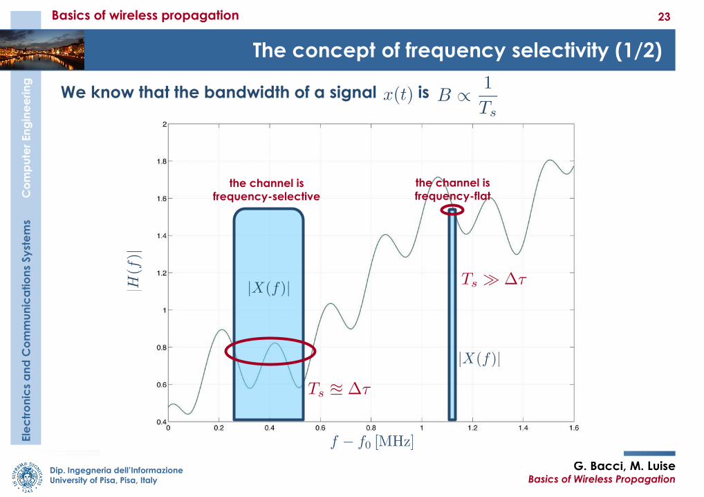
We know that the bandwidth of a signal is
the channel is
frequency-flatthe channel is
frequency-selective
Ele
ctr
on
ics
an
d C
om
mu
nic
atio
ns
Sy
ste
ms
Co
mp
ute
r En
gin
ee
rin
g
G. Bacci, M. LuiseBasics of Wireless Propagation
24
Dip. Ingegneria dell’Informazione
University of Pisa, Pisa, Italy
The concept of frequency selectivity (2/2)
Basics of wireless propagation
The frequency selectivity depends on the statistics
of the channel and of the input signal
There is a practical way to assess the frequency selectivity of a channel:
o : frequency-flat channel
o : frequency-selective channel
Example:
o urban scenarios:
o 3G and 4G signals:
Some form of equalization is needed to combat the frequency selectivity
cB B
cB B
1 ms , Bc 1 MHz/100=10 kHz
Ele
ctr
on
ics
an
d C
om
mu
nic
atio
ns
Sy
ste
ms
Co
mp
ute
r En
gin
ee
rin
g
G. Bacci, M. LuiseBasics of Wireless Propagation
25
Dip. Ingegneria dell’Informazione
University of Pisa, Pisa, Italy
Time-varying frequency-flat channels (1/5)
Basics of wireless propagation
Due to the relative motion between the transmitter and the receiver, the
communication medium (the wireless channel) evolves through time:
For simplicity, assume a frequency-flat channel:
And so
fading process
100c s sB B T T
s iT i
Ele
ctr
on
ics
an
d C
om
mu
nic
atio
ns
Sy
ste
ms
Co
mp
ute
r En
gin
ee
rin
g
G. Bacci, M. LuiseBasics of Wireless Propagation
26
Dip. Ingegneria dell’Informazione
University of Pisa, Pisa, Italy
Time-varying frequency-flat channels (2/5)
Basics of wireless propagation
To study time and frequency characteristics of A(t), let’s use the kinematic
model for the MS:
Due to the Doppler effect, each frequency component is shifted at the
receiver side by its Doppler shift :
( )x t
( ) ( )exp( 2 )= y t x t j ft
Ele
ctr
on
ics
an
d C
om
mu
nic
atio
ns
Sy
ste
ms
Co
mp
ute
r En
gin
ee
rin
g
G. Bacci, M. LuiseBasics of Wireless Propagation
27
Dip. Ingegneria dell’Informazione
University of Pisa, Pisa, Italy
Time-varying frequency-flat channels (3/5)
Basics of wireless propagation
In reality, when we have rich multipath, the incident wave comes from a
variety of different angles, and the Doppler shift has not just one single
value:
The values of the Doppler effect, are spread around a certain interval of
Doppler frequencies, according to the different ai’s. The receievd signal is
1f
2f
3f
31 2
1 1 2 2 3 3( ) exp( 2 ) exp( 2 ) exp( 2 ) ... ( ) ( ) ( ) = + + + = jj j
y t e j f t e j f t e j f t x t A t x t
Ele
ctr
on
ics
an
d C
om
mu
nic
atio
ns
Sy
ste
ms
Co
mp
ute
r En
gin
ee
rin
g
G. Bacci, M. LuiseBasics of Wireless Propagation
28
Dip. Ingegneria dell’Informazione
University of Pisa, Pisa, Italy
Time-varying frequency-flat channels (3/5)
Basics of wireless propagation
When the «scatterers» (i.e., the objects) in the scenario are very many, the
Doppler shifts are distributed with continuity in the interval [-f0v/c; f0v/c]
1f
2f
3f
The decomposition of A(t) into many Doppler components becomes a
continuos Doppler spectrum, confined within the interval [-f0v/c; f0v/c]
Ele
ctr
on
ics
an
d C
om
mu
nic
atio
ns
Sy
ste
ms
Co
mp
ute
r En
gin
ee
rin
g
G. Bacci, M. LuiseBasics of Wireless Propagation
29
Dip. Ingegneria dell’Informazione
University of Pisa, Pisa, Italy
Time-varying frequency-flat channels (4/5)
Basics of wireless propagation
The behavior of A(t) is given by the impact of the Doppler effect over the
received signal
A key parameter is the maximum Doppler shift at the carrier frequency f0,
called the Doppler spread fD:
Using the Clarke’s model, we can
compute the power spectral density
(PSD) of the random process A(t):
Ele
ctr
on
ics
an
d C
om
mu
nic
atio
ns
Sy
ste
ms
Co
mp
ute
r En
gin
ee
rin
g
G. Bacci, M. LuiseBasics of Wireless Propagation
30
Dip. Ingegneria dell’Informazione
University of Pisa, Pisa, Italy
Example of Flat Fading
Signal amplitude
|A(t)| received at f0=1
GHz by a mobile
terminal
travelling at v=20km/h
in an urban area
~ 30 msec
t~ 300 bits @ 9.6 kb/sec
Ele
ctr
on
ics
an
d C
om
mu
nic
atio
ns
Sy
ste
ms
Co
mp
ute
r En
gin
ee
rin
g
G. Bacci, M. LuiseBasics of Wireless Propagation
31
Dip. Ingegneria dell’Informazione
University of Pisa, Pisa, Italy
The concept of time selectivity 1/2
Basics of wireless propagation
The time selectivity depends on the statistics of the
channel and of the input signal
Selectivity is quantified through the Coherence Time Tc:
1 1
10 100c
D
Tf
=
: static channel (also means )
: time-selective channel
S cT T
S cT T
Df B
Ele
ctr
on
ics
an
d C
om
mu
nic
atio
ns
Sy
ste
ms
Co
mp
ute
r En
gin
ee
rin
g
G. Bacci, M. LuiseBasics of Wireless Propagation
32
Dip. Ingegneria dell’Informazione
University of Pisa, Pisa, Italy
The concept of time selectivity 2/2
Basics of wireless propagation
Example (GSM on Frecciarossa): v=324 km/h= 90 m/s, f0=1.8 GHz
BUT the burst time is TB=546.5 ms
1 1
10 100c
D
Tf
=
Rs=270.833 kbaud Ts=3.7 ms
fD=540 Hz TC=18.5 ms
Ele
ctr
on
ics
an
d C
om
mu
nic
atio
ns
Sy
ste
ms
Co
mp
ute
r En
gin
ee
rin
g
G. Bacci, M. LuiseBasics of Wireless Propagation
33
Dip. Ingegneria dell’Informazione
University of Pisa, Pisa, Italy
Bibliography
[01] T.S. Rappaport, Wireless Communications: Principles and Practice, 2nd ed. Upper
Saddle River, NJ: Prentice-Hall, 2002.
[02] A.F. Molisch, Wireless Communications. West Sussex, UK: J. Wiley & Sons, 2005.
[03] A. Mehrotra, GSM System Engineering. Boston, MA – London, UK: Artech House,
1996.
[04] J.D. Parsons, The Mobile Radio Propagation Channel. Chichester, UK: J. Wiley &
Sons, 2000.
[05] M. Pätzold, Mobile Fading Channels. Chichester, UK: J. Wiley & Sons, 2002.
[06] B. Sklar, “Rayleigh fading channels in mobile digital communication sys- tems,
Part I: Characterization,” IEEE Commun. Mag., vol. 35, no. 7, pp. 90–100, July
1997.
[07] B. Sklar, “Rayleigh fading channels in mobile digital communication systems,
Part II: Mitigation,” IEEE Commun. Mag., vol. 35, no. 7, pp. 102–109, July 1997.
[08] M. Hata, “Empirical formula for propagation loss in land mobile radio services,”
IEEE Trans. Veh. Technol., vol. 29, no. 3, pp. 317–325, Aug. 1980.
[09] R.H. Clarke, “A statistical theory of mobile-radio reception,” Bell Systems
Technical Journal, vol. 47, no. 6, pp. 957–1000, July-Aug. 1968.
Bibliography


![[Massimo Livi-Bacci] Population and Nutrition an (Bookos.org)](https://static.documents.pub/doc/80x56/55cf9b74550346d033a62075/massimo-livi-bacci-population-and-nutrition-an-bookosorg.jpg)
