59
Introduction 1 1 Computer Networking Introduction http://duda.imag.fr Prof. Andrzej Duda [email protected]

Introduction
1
1
Computer Networking
Introduction
http://duda.imag.fr
Prof. Andrzej [email protected]
Introduction
2
2
Course goals Understand TCP/IP and networking concepts Approach
bottom-up, descriptive, use Internet as an example wrap up with the application layer seen during the 1st year course
Organization 27 h course demos, exercises slides are not exhaustive - you must take notes and ask questions! bonus questions: 5 good answers get 1 point (limited to 5 per
person)
Exam closed-book: no personal notes, textbook, etc., are allowed we provide a summary of required factual knowledge
Your team Andrzej Duda (in English), Olivier Alphand (en français)

Introduction
3
3
Networking lab Important part of the course (separate grade)
perform required operations, write lab reports, final exam cannot be repeated
grade < 8, you repeat your year!
Goals acquire practical knowledge plug cables, configure hosts and routers, monitor, measure,
program network applications
Rooms D200 and D201: 80 PCs with multiple network interfaces network equipement: hubs, switches, routers isolated from the rest of the network
Your team Olivier Alphand, Sébastien Viardot, TAs

Introduction
4
4
Contents
Introduction architecture, performance
Data Link PPP, LAN (Ethernet, 802.11)
Network layer IP, ATM Routing
Transport reliable transfer protocols TCP, UDP, sockets congestion control
Introduction
5
5
Course support Web site
http://duda.imag.fr/2at
J. Kurose, K. Ross “Computer Networking”, 4thedition, Addison Wesley, 2007
J. Kurose, K. Ross, "Analyse structurée des réseaux.Des applications de l'internet aux infrastructures destélécommunications." Pearson Education France,2003
Others L. Toutain "Réseaux locaux et Internet", 3me édition,
Hermes, 2003 W. R. Stevens “TCP/IP illustrated, Volume I”, Addison
Wesley (Very detailed, experimental hands-on description ofTCP/IP)
Introduction
6
6
Overview
Network architectures recall on the Internet protocol architectures
how entities cooperate?
interconnection structure which entities are connected?
related protocols how and where different functionalities are implemented?
Performance transmission propagation bandwidth-delay product queueing delay

Introduction
7
7
Inside the Internet
Between end systems TCP protocol for reliable
transmission
Inside the network core IP protocol: forwarding packets
between routers
Between routers or betweenend system and router high speed link: ATM, POS (Packet
over SONET), satellite links access network: Ethernet, modem,
xDSL, HFC

Introduction
8
8
Network structure
network edge:applications and hosts
network core: routers network of networks
access networks,physical media:communication links
We are now going to delve a bit more deeply into the components of acomputer network. We begin at the edge of network and look at thecomponents with which we are most familiar--the computers (for example,PCs and workstations) that we use on a daily basis. Then, moving from thenetwork edge to the network core we have switchs and routers. Finally, wehave the access network – the physical link(s) that connect an end system to itsedge router – that is, to the first router on a path from the end system to anyother end system.

Introduction
9
9
The network edge:
end systems (hosts): run application programs e.g., WWW, email at “edge of network”
client/server model client host requests, receives
service from server e.g., WWW client (browser)/
server, email client/server
peer-peer model: symmetric host interaction e.g. teleconferencing
In computer networking jargon, the computers that we use on a daily basis areoften referred to as hosts or end systems. They are referred to as hosts becausethey host (run) application-level programs such as a Web browser or serverprogram, or an e-mail program. They are also referred to as end systemsbecause they sit at the edge of the network.Hosts are sometimes further divided into two categories: clients and servers.Informally, clients often tend to be desktop PCs or workstations, whereasservers are more powerful machines. But there is a more precise meaning of aclient and a server in computer networking. In the so-called client/servermodel, a client program running on one end system requests and receivesinformation from a server running on another end system. This client/servermodel is undoubtedly the most prevalent structure for Internet applications.The Web, e-mail, file transfer, remote login (for example, Telnet), newsgroups,and many other popular applications adopt the client/server model.
The other model used in computer networks is referred to as peer-to-peermodel. In this model the two hosts takes the same role and run the sameprograms. A typical example of peer-to-peer application is theteleconferencing.

Introduction
10
10
The Network Core
mesh of interconnectedrouters
the fundamental question:how is data transferredthrough net? circuit switching:
dedicated circuit percall: telephone nets
packet-switching: datasent thru net in discrete“chunks” (IP)
The network core is the mesh of routers that interconnect the end systems. In the figure, wehighlights the network core in the thick, shaded lines.There are two fundamental approaches towards building a network core: circuit switching andpacket switching. In circuit-switched networks, the resources needed along a path (buffers, linkbandwidth) to provide for communication between the end systems are reserved for theduration of the session. In packet-switched networks, these resources are not reserved; asession's messages use the resource on demand, and as a consequence, may have to wait (thatis, queue) for access to a communication link.The ubiquitous telephone networks are examples of circuit-switched networks. Consider whathappens when one person wants to send information (voice or facsimile) to another over atelephone network. Before the sender can send the information, the network must firstestablish a connection between the sender and the receiver.In modern packet-switched networks, the source breaks long messages into smaller packets.Between source and destination, each of these packets can take different communication linksand packet switches (also known as routers). Packets are transmitted over each communicationlink at a rate equal to the full transmission rate of the link. Most packet switches use store-and-forward transmission at the inputs to the links. Store-and-forward transmission means that theswitch must receive the entire packet before it can begin to transmit the first bit of the packetonto the outbound link. Thus store-and-forward packet switches introduce a store-and-forwarddelay at the input to each link along the packet's route. This delay is proportional to thepacket's length in bits. In particular, if a packet consists of L bits, and the packet is to beforwarded onto an outbound link of R bps, then the store-and-forward delay at the switch isL/R seconds.

Introduction
11
11
Access networks and physical media
How to connect endsystems to edge router?
residential access nets institutional access
networks (school,company)
mobile access networks
Characteristics: bandwidth (bits per
second) of accessnetwork
shared or dedicated
The access networks are the physical link(s) that connect an end system to itsedge router.The figure shows the access networks' links highlighted in thick,shaded lines.Access networks can be loosely divided into three categories:o Residential access networks, connecting a home end system into thenetworko Institutional access networks, connecting an end system in business oreducational institution into the networko Mobile access networks, connecting a mobile end system into thenetworkThese categories are not hard and fast; some corporate end systems may welluse the access network technology that we ascribe to residential accessnetworks, and vice versa.

Introduction
12
12
Internet design principles
Cerf and Kahn’s internetworking principles: minimalism, autonomy - no internal changes required to
interconnect networks best effort service model stateless routers decentralized control
Small number of layers compromise between performance and flexibility
thin layers encourage flexibility, but increases overhead
Define today’s Internet architecture

Introduction
13
13
TCP/IP Architecture
HTTP
TCP
IP
Ethernet
Physical
dataHTTP request
TCP segment
IP packet
Ethernet frame
GET / …
GET / …
GET / …
GET / …

Introduction
14
The Application Layer is responsible for supporting network applications. The application layerincludes many protocols, including HTTP to support the Web, SMTP to support electronic mail,and FTP to support file transfer. We shall see in Chapter 2 that it is very easy to create our ownnew application-layer protocols.
14
Application Layer
Application layer supports network application applications that are distributed over the network applications that communicates through the network
Many known protocols FTP: file transfer SMTP: email protocol HTTP:web protocol
An application uses UDP or TCP, it is a designer’s choice Interface with the transport layer
use for example the socket API: a library of C functions socket also means (IP address, port number)

Introduction
15
Physical, data link and network layers are sufficient to build a packet transport system betweencomputers. However, this is not enough for the programmer. When you write a low-levelprogram which uses the network (as we will do in this lecture), you do not handle packets, butdata. The primary goal of the transport layer is to provide the programmer with an interface tothe network.Second, the transport layer uses the concept of port. A port is a number which is used locally (onone machine) and identifies the source and destination of the packet inside the machine. We willcome back to the concept of ports later in this chapter.The transport layer exists in two varieties: unreliable and reliable. The unreliable variety simplysends packets, and does not attempt to guarantee any delivery. The reliable variety, in contrast,makes sure that data does reach the destination, even if some packets may be lost from time totime. In the Internet there are two transport protocols, TCP and UDP, either of which cantransport application-layer messages. TCP provides a connection-oriented service to itsapplications. This service includes guaranteed delivery of application-layer messages to thedestination and flow control (that is, sender/receiver speed matching). TCP also segments longmessages into shorter segments and provides a congestion control mechanism, so that a sourcethrottles its transmission rate when the network is congested. The UDP protocol provides itsapplications a connectionless service, which is very much a no-frills service.
15
Transport Layer
Why a transport layer ? transport layer = makes network service available to
programs is end-to-end only, not in routers
In TCP/IP there are two transport protocols UDP (user datagram protocol)
unreliable offers a datagram service to the application (unit of information is
a message) TCP (transmisssion control protocol)
reliable offers a stream service (unit of information is a byte)

Introduction
16
16
Layering: logical communication
E.g.: transport take data from
app add addressing,
reliability checkinfo to form“datagram”
send datagramto peer
wait for peer toack receipt
analogy: postoffice
applicationtransportnetwork
linkphysical
applicationtransportnetwork
linkphysical
applicationtransportnetwork
linkphysical
applicationtransportnetwork
linkphysical
networklink
physical
data
data
transport
transport
data
ack

Introduction
17
17
TCP

Introduction
18
Modern networks have more than physical and data link. The network layer is the set ofmechanisms that can be used to send packets from one computer to another in the world. Thereare two types of networks:With Packet switching, data packets can be carried together on the same link. They aredifferentiated by addressing information. Packet switching is the basis for all data networkstoday, including the Internet, public data networks such as Frame Relay, X.25, or ATM.Circuit Switching is the way telephone networks operate. A circuit emulates the physical signalsof a direct end-to-end cable. When computers are connected by a circuit switched network, theyestablish a direct data link over the circuit. This is used today for modem access to a datanetwork.Modern circuit switches are based on byte multiplexing and are thus similar to packet switches,with the main difference that they perform non-statistical multiplexing (see later in this chapter).A network has Intermediate systems (ISs): those are systems that send data to next ISs or to thedestination. Using interconnected ISs saves cable and bandwidth. ISs are known under variousterms depending on the context: routers (TCP/IP, AppleTalk,…), switches (X.25, Frame Relay,ATM, telephone), communication controllers (SNA), network nodes (APPN).The Internet's network layer has two principle components. It has a protocol that defines thefields in the IP datagram as well as how the end systems and routers act on these fields. Thisprotocol is the celebrated IP protocol. There is only one IP protocol, and all Internet componentsthat have a network layer must run the IP protocol. The Internet's network layer also containsrouting protocols that determine the routes that datagrams take between sources and destinations.The Internet has many routing protocols.
18
Network Layer Set of functions required to transfer packets end-to-end
(from host to host) hosts are not directly connected - need for intermediate systems examples: IP, Appletalk, IPX
Intermediate systems routers: forward packets to the final destination interconnection devices
router
H1
H2
H3
H4S1
S2
router

Introduction
19
19
IP
Server WWWWWW client
Netscapehttpd
physical
Ether
IP
physical
Ether
IP
dest router129.88.38 R4
R1R3
R2R4
R5
router R3
IP packet
dest address:129.88.38.10
Routing Table of R3
Modern networks have more than physical and data link. The network layer isthe set of mechanisms that can be used to send packets from one computer toanother in the world. There are two types of networks:With Packet switching, data packets can be carried together on the same link.They are differentiated by addressing information. Packet switching is the basisfor all data networks today, including the Internet, public data networks such asFrame Relay, X.25, or ATM.Circuit Switching is the way telephone networks operate. A circuit emulatesthe physical signals of a direct end-to-end cable. When computers areconnected by a circuit switched network, they establish a direct data link overthe circuit. This is used today for modem access to a data network.Modern circuit switches are based on byte multiplexing and are thus similar topacket switches, with the main difference that they perform non-statisticalmultiplexing (see later in this chapter).A network has Intermediate systems (ISs): those are systems that send data tonext ISs or to the destination. Using interconnected ISs saves cable andbandwidth. ISs are known under various terms depending on the context:routers (TCP/IP, AppleTalk,…), switches (X.25, Frame Relay, ATM,telephone), communication controllers (SNA), network nodes (APPN).The Internet's network layer has two principle components. It has a protocolthat defines the fields in the IP datagram as well as how the end systems androuters act on these fields. This protocol is the celebrated IP protocol. There isonly one IP protocol, and all Internet components that have a network layermust run the IP protocol. The Internet's network layer also contains routingprotocols that determine the routes that datagrams take between sources anddestinations. The Internet has many routing protocols.

Introduction
20
Physical Layer: The job of the physical layer is to move the individual bits within the framefrom one node to the next. The protocols in this layer are again link dependent, and furtherdepend on the actual transmission medium of the link (for example, twisted-pair copper wire,single-mode fiber optics). For example, Ethernet has many physical layer protocols: one fortwisted-pair copper wire, another for coaxial cable, another for fiber, and so on. In each case, abit is moved across the link in a different way.Link Layer: The services provided at the link layer depend on the specific link-layer protocolthat is employed over the link. For example, some protocols provide reliable delivery on a linkbasis, that is, from transmitting node, over one link, to receiving node. The process is analogousto the postal worker at a mailing center who puts a letter into a plane that will deliver the letter tothe next postal center along the route. Examples of link layers include Ethernet and PPP; in somecontexts, ATM and frame relay can be considered link layers. As datagrams typically need totraverse several links to travel from source to destination, a datagram may be handled bydifferent link-layer protocols at different links along its route. For example, a datagram may behandled by Ethernet on one link and then PPP on the next link. The network will receive adifferent service from each of the different link-layer protocols.
20
Physical LayerData Link Layer
point to pointcables
Ethernetswitch
hosts
H1
H2
H3
frameto H3
Physical transmission = Physicalfunction bits <-> electrical / optical signals transmit individual bits over the
cable: modulation, encoding Frame transmission = Data Link
function bits <-> frames bit error detection packet boundaries in some cases: error correction by
retransmission (802.11) Modems, xDSL, LANs

Introduction
21
21
Protocol architectures
Protocol entity provides a set of services, eg.
connect, send
data multiplexing/demultiplexing construction/analysis of PDUs execution of procedures
Protocol unit (PDU) header: control functions opaque data
Procedures actions to perform protocol functions: e.g. lost packet
retransmission

Introduction
22
22
Protocol architecture
SAP
PDU PDU
procedures
Lower layer protocols
Protocol entity Protocol entity
data
multiplexingSAP
data
demultiplexing
layer nlayer n
layer n-1 layer n-1

Introduction
23
23
Internet protocol stack
Application: supporting networkapplications FTP, SMTP, HTTP, OSPF, RIP
Transport: host-host data transfer TCP, UDP
Network: routing of datagrams fromsource to destination IP
Link: data transfer between neighboringnetwork elements PPP, Ethernet
Physical: bits “on the wire”
Application
Transport
Network
Link
Physical

Introduction
24
24
Layering: physical communication
applicationtransportnetwork
linkphysical
applicationtransportnetwork
linkphysical
applicationtransportnetwork
linkphysical
applicationtransportnetwork
linkphysical
networklink
physical
data
data

Introduction
25
25
Protocol layering and data
Each layer takes data from above adds header information to create new data unit passes new data unit to layer below
applicationtransportnetwork
linkphysical
applicationtransportnetwork
linkphysical
source destinationMMMM
Ht
HtHn
HtHnHl
MMMM
Ht
HtHn
HtHnHl
messagesegmentdatagramframe
PDU
SDU

Introduction
26
26
Encapsulation
HTTP Request
TCP segment
IP packet
Ethernet frame
data
data
data
header
header
header

Introduction
27
27
OSI ISO Model
Application
Presentation
Session
Transport
Network
Data link
Physical
Common functions
Interchangable formats
Organizing dialog
Reliable transmission
Forwarding in the network
Transmission between two nodes
Signal transmission

Introduction
28
28
ATM protocol stack
Application: native applications, otherprotocols LAN Emulation, IP, Signaling
Transport: host-host data transfer SSCOP
Adaptation: adapt the ATM layer todifferent types of applications circuit emulation, real-time data AAL5 suitable for IP traffic
ATM: cell switching over virtual circuits Physical: bits “on the wire”, usually fiber
Application
Transport
Adaptation
ATM
Physical

Introduction
29
29
LAN stack
Management: e.g. constructforwarding tables SNAP: Spanning Tree protocol
LLC: multiplex different protocols IP, IPX, SNAP
MAC: medium access 802.3 (Ethernet), 802.4 (Token Ring), 802.5
(Token Bus), 802.11 (Wi-Fi)
Physical: bits “on the wire”
Management
LLC
MAC
Physical
Data-link

Introduction
30
30
Interconnection structure - layer 3
host
router
switch(bridge)
interconnectionlayer 3
VLAN
subnetwork 1
subnet 3
subnet 2
interconnectionlayer 2

Introduction
31
31
Interconnection at layer 2
Switches (bridges) interconnect hosts logically separate groups of hosts (VLANs) managed by one entity
Type of the network broadcast
Forwarding based on MAC address flat address space forwarding tables: one entry per host works if no loops
careful management Spanning Tree protocol
not scalable

Introduction
32
32
Transport
Network
Physical
Application5
4
3
2
1
MAC
Physical
MACL2 PDU
(MAC Frame)
host switch (bridge)
LLC
Protocol architecture
Switches are layer 2 intermediate systems Transparent forwarding Management protocols (Spanning Tree, VLAN)
LLC
L2 PDU(LLC Frame)

Introduction
33
33
802.3
LLC
SNAP
data
-link
Physical layer
Protocols
Ethernet v2
netw
ork
IP
data
management

Introduction
34
34
Interconnection at layer 3
Routers interconnect subnetworks logically separate groups of hosts managed by one entity
Forwarding based on IP address structured address space routing tables: aggregation of entries works if no loops - routing protocols (IGP - Internal Routing
Protocols) scalable inside one administrative domain

Introduction
35
35
Protocol architecture
Routers are layer 3 intermediate systems Explicit forwarding
host has to know the address of the first router
Management protocols (control, routing, configuration)
Transport
Network
Physical
Application5
4
3
2
1
MAC
Physical
MACL2 PDU
(MAC Frame)
host switch (bridge)
LLC LLC
Transport
Network
Physical
Application 5
4
3
2
1
MAC
router
LLC
L2 PDU(MAC Frame)
L3 PDU(IP packet)

Introduction
36
36 data
-link
Protocols
Ethernet v2
netw
ork
IP
routing
ARP
TCP
OSPF RIPDHCP
ICMP
tran
spor
tap
plic
atio
n
IGMP
UDP
DNS
naming configuration routing
control groups
addressresolution

Introduction
37
37
Autonomous systems
host
switch(bridge)
interconnectionlayer 2
interconnectionlayer 3
VLAN
subnetwork
autonomoussystem
borderrouter
internalrouter

Introduction
38
38
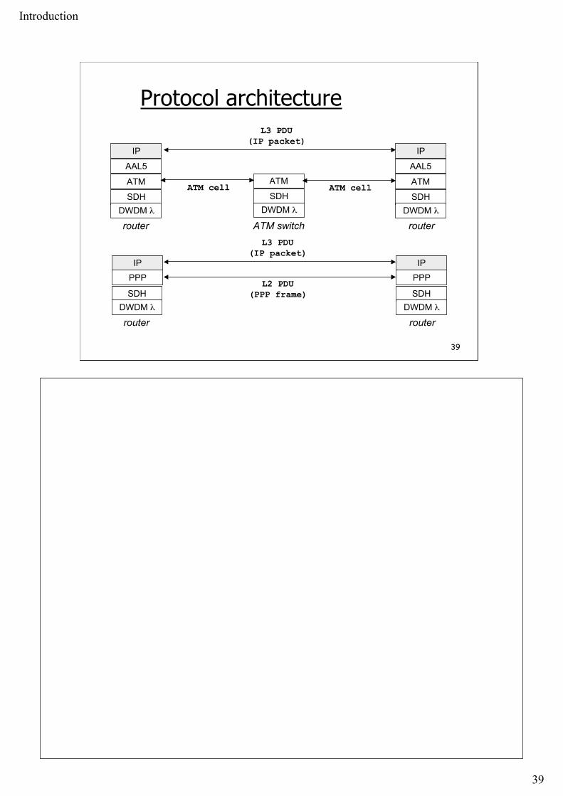
Overlaid stacks? Long-haul links
Fiber at physical layer (SONET/SDH) Dense Wave Division Multiplexing (DWDM)
one color of the light λ
Different technologies ATM Frame Relay POS (Packet over SONET/SDH)
Type of the network NBMA (Non Broadcast Multiple Access) or point-to-point
Complex protocol hierarchies IP over ATM
Introduction
39
39
Protocol architecture
IP
SDH
ATMATM cell
router ATM switch
AAL5
router
ATM cell
L3 PDU(IP packet)
DWDM λSDH
ATM
DWDM λ
IP
SDH
ATM
AAL5
DWDM λ
PPP
SDH
router routerDWDM λ
PPP
SDHDWDM λ
L2 PDU(PPP frame)
IP
L3 PDU(IP packet)
IP

Introduction
40
40
Internet
NAP, GIX, IXP
subnetworks
borderrouter
autonomoussystem

Introduction
41
41
Interconnection of AS
Border routers interconnect AS
NAP or GIX, or IXP exchange of traffic - peering
Route construction based on the path through a series of AS based on administrative policies routing tables: aggregation of entries works if no loops and at least one route - routing protocols
(EGP - External Routing Protocols)

Introduction
42
42 data
-link
Protocols
Ethernet v2
netw
ork
IP
routing
ARP
TCP
BGP
ICMP
tran
spor
tap
plic
atio
n
control
addressresolution

Introduction
43
43
Performance
Bit Rate (débit binaire) of a transmission system bandwidth, throughput number of bits transmitted per time unit units: b/s or bps, kb/s = 1000 b/s, Mb/s = 10e+06 b/s,
Gb/s=10e+09 b/s OC3/STM1 - 155 Mb/s, OC12/STM4 - 622 Mb/s, and
OC48/STM-16 - 2.5 Gb/s, OC192/STM-48 10 Gb/s
Latency or Delay time interval between the beginning of a transmission and
the end of the reception RTT - Round-Trip Time

Introduction
44
44
Delay in packet-switched networkspackets experience delay
on end-to-end path four sources of delay at
each hop
nodal processing: check bit errors determine output link
A
B
propagation
transmission
nodalprocessing queuing
queuing time waiting at output link for
transmission depends on congestion level of node
transmission: depends on packet length and link
bandwidth propagation:
depends on distance between nodes
As a packet travels from one node (host or router) to the subsequent node (hostor router) along this path, the packet suffers from several different types ofdelays at each node along the path. The most important of these delays are thenodal processing delay, queuing delay, transmission delay, and propagationdelay; together, these delays accumulate to give a total nodal delay. Processing Delay The time required to examine the packet's header and determine where todirect the packet is part of the processing delay. The processing delay can alsoinclude other factors, such as the time needed to check for bit-level errors inthe packet that occurred in transmitting the packet's bits from the upstreamrouter to router A. Processing delays in high-speed routers are typically on theorder of microseconds or less. After this nodal processing, the router directsthe packet to the queue that precedes the link to router B. (In Section 4.6 wewill study the details of how a router operates.)

Introduction
45
45
Delay
Transmission
Propagation
first bit
Waiting Time End-to-enddelay
last bit
packet
Distancetime

Introduction
46
46
Performance
Latency Latency = Propagation + Transmission + Wait Propagation = Distance / Speed
copper : Speed = 2.3×10⁸ m/s glass : Speed = 2×10⁸ m/s
Transmission = Size / BitRate
5 µs/km New York - Los Angeles in 24 ms
request - 1 byte, response - 1 byte: 48 ms 25 MB file on 10 Mb/s: 20 s
World tour in 0.2 s
Introduction
47
47
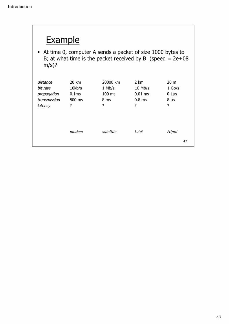
Example At time 0, computer A sends a packet of size 1000 bytes to
B; at what time is the packet received by B (speed = 2e+08m/s)?
distance 20 km 20000 km 2 km 20 mbit rate 10kb/s 1 Mb/s 10 Mb/s 1 Gb/spropagation 0.1ms 100 ms 0.01 ms 0.1µstransmission 800 ms 8 ms 0.8 ms 8 µslatency ? ? ? ?
modem satellite LAN Hippi

Introduction
48
48
Example At time 0, computer A sends a packet of size 1000 bytes to
B; at what time is the packet received by B (speed = 2e+08m/s)?
distance 20 km 20000 km 2 km 20 mbit rate 10kb/s 1 Mb/s 10 Mb/s 1 Gb/spropagation 0.1ms 100 ms 0.01 ms 0.1µstransmission 800 ms 8 ms 0.8 ms 8 µslatency 800.1 ms 108 ms 0.81 ms 8.1 µs
modem satellite LAN Hippi

Introduction
49
49
Bandwidth-Delay Product
Bandwidth-Delay product how many bits should we send before the arrival of the first
bit? good utilization - keep the pipe filled!
Delay
Bandwidth

Introduction
50
50
Bandwidth-Delay Product
File transfer: 1 Mbit, 100 ms delay 1 Mb/s link, D×b = 0.1 Mbit
10 transmissions, 10% each time
1 Gbit/s link, D×b = 100 Mbit 1 transmission, pipe not filled

Introduction
51
As an illustration of the effect of propagation, consider the scenario above.
The number β is called the bandwidth-delay product. It expresses the number of bits in the pipe.We will find it important in the rest of the lecture - the performance of protocols depends on thisparameter.
51
Bandwidth-Delay Product Consider the scenario :
B says: “stop”
last bit sent by A arrives
β = 2Db
β = maximum number of bits B can receive after saying stop
large β means: delayed feedback
amount of data “in the pipe”
A
B
time

Introduction
52
This example is a simple protocol, often used, for repairing packet or message losses. The idea issimple
- identifiy all packets with some number or some other means- when you send one packet, wait until you receive a confirmation- after some time, if no confirmation arrives, consider that the packet has been lost andretransmit.
Compute the maximum throughput of this protocol, assuming the source has an infinite supply ofpackets to send, the destination generates the confirmation instantly, and the bit rate of thechannel is constant.
52
A Simple Protocol: Stop and Go
Packets may be lost during transmission:bit errors due to channel imperfections, variousnoises.
Computer A sends packets to B; B returns anacknowledgement packet immediately to confirm thatB has received the packet;A waits for acknowledgement before sending a newpacket; if no acknowledgement comes after a delayT1, then A retransmits

Introduction
53
This example is a simple protocol, often used, for repairing packet or message losses. The idea issimple
- identifiy all packets with some number or some other means- when you send one packet, wait until you receive a confirmation- after some time, if no confirmation arrives, consider that the packet has been lost andretransmit.
Compute the maximum throughput of this protocol, assuming the source has an infinite supply ofpackets to send, the destination generates the confirmation instantly, and the bit rate of thechannel is constant.
53
A Simple Protocol: Stop and Go
Question: What is the maximum throughputassuming that there are no losses?notation: packet length = L, constant (in bits); acknowledgement length = l, constant channel bit rate = b; propagation = D processing time = 0

Introduction
54
54
Solution (1)packet P1 sent
packet P1 acknowledged
T=L/b 2D
T’=l/b
cycle time = T + 2D + T’
useful bits per cycle time = L
throughput = Lb / (L + l + 2Db)= b /(ω + β/L)
with ω=(L+l)/L=overhead and β=2Db=bandwidth-delayproduct
A
B
time

Introduction
55
55
Solution (2)
distance 20 km 20000 km 2 km 20 mbit rate 10kb/s 1 Mb/s 10 Mb/s 1 Gb/spropagation 0.1ms 100 ms 0.01 ms 0.1µstransmission 800 ms 8 ms 0.8 ms 8 µsreception time 800.1 ms 108 ms 0.81 ms 8.1 µs
modem satellite LAN Hippiβ=2Db 2 bits 200 000 bits 200 bits 200 bitsthroughput = b ×99.98% 3.8% 97.56% 97.56%
Introduction
56
56
λ
µ
λ
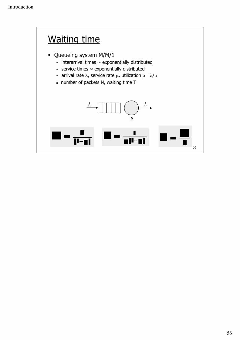
Waiting time
Queueing system M/M/1 interarrival times ~ exponentially distributed service times ~ exponentially distributed arrival rate λ, service rate µ, utilization ρ= λ/µ
number of packets N, waiting time T

Introduction
57
57
λ [p/s] 10 40 60 701/λ [ms] 100 25 16 14
T [ms] 13 23 43 76
Waiting time
Average packet length 1500 bytes link with 1 Mb/s bit rate (propagation = 0)
transmission time 12 ms service rate 83 packet/s

Introduction
58
58
Waiting time
T
ρ1

Introduction
59
59
Summary
Network architectures protocol architectures
different protocol stacks, overlaid stacks
interconnection structure switches, routers
related protocols complex protocol families
Performance transmission propagation bandwidth-delay product queueing delay


