40
Computer Networks: Multiplexing Dr. Taek M. Kwon, Ph.D. Department of Electrical Engineering, UMD EE1001

Computer Networks:
Multiplexing
Dr. Taek M. Kwon, Ph.D.
Department of Electrical Engineering,
UMD
EE1001

Outline
EE 4321
Multiplexing

EE 4321: Computer Networks
• EE Technical Elective Course, 3 credits
• Network Lab (MWAH 60)
• Course Objective: to learn characteristics
of network transmission media, protocol
architectures, routing algorithms, various
LAN technologies, WAN technologies, and
network programming.

Multiplexer (Mux)
y
x0
x1
x2
x3
S1 S0
S1 S0 y
0 0 x0
0 1 x1
1 0 x2
1 1 x3

Demultiplexer (Demux)
y
x0
x1
x2
x3
S1 S0
S1 S0 x3 x2 x1 x0
0 0 - - - y
0 1 - - y -
1 0 - y - -
1 1 y - - -

Mux/Demux
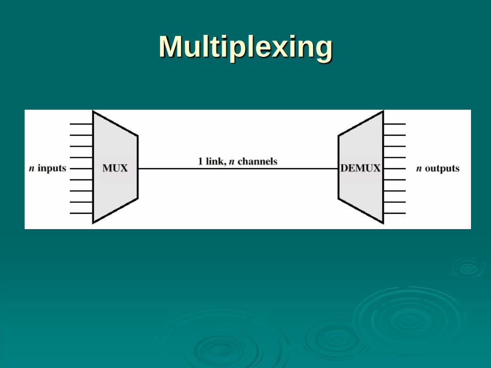
Multiplexing

Multiplexing Forms
Time Division Multiplexing (TDM)
Synchronous TDM – Each signal source is
interleaved using a fixed time slot assigned.
Statistical TDM -- Time slots are not preassigned.
Rather, data are transmitted using the available time
slots.
Frequency Division Multiplexing (FDM) – A
number of signals are carried simultaneously on
the same medium by allocating to each signal a
different frequency band.
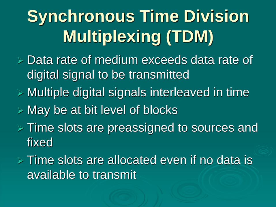
Synchronous Time Division
Multiplexing (TDM)
Data rate of medium exceeds data rate of
digital signal to be transmitted
Multiple digital signals interleaved in time
May be at bit level of blocks
Time slots are preassigned to sources and
fixed
Time slots are allocated even if no data is
available to transmit

Time Division Multiplexing

TDM
System

TDM Link Control
No headers and trailers
Data link control protocols not needed
Flow control Data rate of multiplexed line is fixed
If one channel receiver can not receive data, the others must carry on
The corresponding source must be quenched
This leaves empty slots
Error control Errors are detected and handled by individual channel
systems

Digital Carrier Systems
Hierarchy of TDM
USA/Canada/Japan use one system
ITU-T use a similar (but different) system
US system based on DS-1 format
Multiplexes 24 channels (64Kbps/channel)
Each frame has 8 bits per channel plus one
framing bit
193 bits per frame (24x8 +1 =193)
Single voice channel =8KHz (Nyquist rate=2B,
4Kx2=8K Samples per sec, 8bit per sample)

Digital Carrier Systems
For voice each channel contains one word of digitized data PCM at 8000 samples per sec
Data rate 8000x193 = 1.544Mbps (193=24x8+1) DS1, T1
Same format for digital data 23 channels of data
24th channel is reserved for a special sync byte

Digital Carriers (TDM
Hierarchy)
Digital Signal
Designation
Bandwidth/dat
a rate
Channels
(DS0s)
Carrier
designation
DS0 64 kbps 1
DS1 1.544 Mbps 24 T1
DS1C 3.152 Mbps 48 T1c
DS2 6.312 Mbps 96 T2
DS3 44.736 Mbps 672 T3 = 7xT2
DS4 274.176 Mbps 4032 T4 = 6xT3
DS5 400.352 Mbps 5760 T5 = 60 xT2
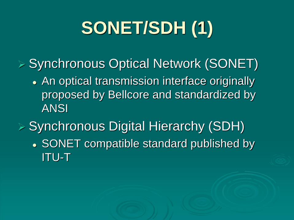
SONET/SDH (1)
Synchronous Optical Network (SONET)
An optical transmission interface originally
proposed by Bellcore and standardized by
ANSI
Synchronous Digital Hierarchy (SDH)
SONET compatible standard published by
ITU-T

SONET/SDH (2)
Signal Hierarchy
Synchronous Transport Signal level 1 (STS-1)
or Optical Carrier level 1 (OC-1)=51.84 Mbps,
51.88x10⁶/65K=810 DS0 channels
STS-3/OC-3, 155.52 Mbps=51.84x3 Mbps
STS-192/OC-192, 9953.28 Mbps = 51.84x192
Mbps
STS-768/OC-768, 40Gbps = 51.84x768 Mbps
= 622,080xDS0
ITU-T lowest rate is 155.52 Mbps (STM-1)

Statistical TDM
In Synchronous TDM many slots are
wasted
Statistical TDM allocates time slots
dynamically based on demand
Multiplexer scans input lines and collects
data until frame full
Data rate on line lower than aggregate
rates of input lines

Synchronous Vs. Statistical
TDM
A B DC A B DC A B DCSynchronous
TDM
A B DAStatistical
TDM
C

Statistical TDM Frame
Formats

Performance
Output data rate is less than aggregate
input rates (the average amount of input is
less than the capacity of the multiplexed
line).
May cause problems during peak periods
Must buffer inputs but its size is limited

Buffer
Size
and
Delay

Cable Modem Outline
Two channels from cable TV provider dedicated to data
transfer One in each direction
Each channel is shared by a number of subscribers
Scheme needed to allocate capacity
Statistical TDM

Cable Modem Operation
Downstream
Cable scheduler delivers data in small packets
If more than one subscriber active, each gets fraction of
downstream capacity
• May get 500kbps to 20Mbps
Also used to grant (allocate) upstream time slots to subscribers
Upstream
User requests timeslots on shared upstream channel. Dedicated
slots are allocated for this request.
Headend scheduler sends back assignment of future time slots
to subscriber using downstream

Cable Modem Scheme

Frequency Division
Multiplexing

FDM
System

Wavelength Division
Multiplexing
Multiple beams of light at different frequency
Carried by optical fiber
A form of FDM
Each colour of light (wavelength) carries separate data channel
Lab system (Alcatel) --DWDM 128 channels at 200 Gbps each
24 Tbps

Spread Spectrum
important encoding method for wireless
communications
analog & digital data with analog signal
spreads data over wide bandwidth
makes jamming and interception harder
two approaches, both in use:
Frequency Hopping
Direct Sequence

Spread Spectrum Advantages
immunity from noise and multipath
distortion
can hide / encrypt signals
several users can share same higher
bandwidth with little interference
CDM/CDMA Mobile telephones

Frequency Hopping Spread
Spectrum (FHSS)
signal is broadcast over seemingly random
series of frequencies
receiver hops between frequencies in sync
with transmitter
eavesdroppers hear unintelligible blips
jamming on one frequency affects only a
few bits

Frequency Hopping Example

Pseudorandom Numbers
generated by a deterministic algorithm
not actually random
but if algorithm good, results pass reasonable
tests of randomness
starting from an initial seed
need to know algorithm and seed to
predict sequence
hence only receiver can decode signal

FHSS (Transmitter)

Frequency Hopping Spread
Spectrum System (Receiver)

Direct Sequence Spread
Spectrum (DSSS)
each bit is represented by multiple bits
using a spreading code
this spreads signal across a wider
frequency band
has performance similar to FHSS

Direct Sequence Spread
Spectrum Example

Code Division Multiple
Access (CDMA)
a multiplexing technique used with spread
spectrum
given a data signal rate D
break each bit into k chips according to a
fixed chipping code specific to each user
resulting new channel has chip data rate
kD chips per second
can have multiple channels superimposed

CDMA Example

Conclusion
Multiplexing was born out of a simple idea
of sharing medium but effectively solves
the complex connection problem of
modern communications that require a
huge number of interconnections among
machines, devices, and people.


