NBS PUBLICATIONS u.o. L/epanment of Commerce National Bureau of Standards Computer Science and Technology NAT'L INST OF STAND & TECH AlllQb T7fll4b NBS Special Publication 500-122 Guide on Logical Database Design
Transcript
NBS
PUBLICATIONSu.o. L/epanmentof Commerce
National Bureauof Standards
Computer Scienceand Technology
NAT'L INST OF STAND & TECH
AlllQb T7fll4b
NBS Special Publication 500-122
Guide onLogical Database Design
he National Bureau of Standards' was established by an act of Congress on March 3, 1901. Them he
JH Bureau's overall goal is to strengthen and advance the nation's science and technology and facilitate
their effective application for public benefit. To this end, the Bureau conducts research and provides: (1) a
basis for the nation's physical measurement system, (2) scientific and technological services for industry andgovernment, (3) a technical basis for equity in trade, and (4) technical services to promote public safety.
The Bureau's technical work is performed by the National Measurement Laboratory, the National
Engineering Laboratory, the Institute for Computer Sciences and Technology, and the Center for Materials
Science.
The National Measurement Laboratory
Provides the national system of physical and chemical measurement; • Basic Standards^
coordinates the system with measurement systems of other nations and • Radiation Research
furnishes essential services leading to accurate and uniform physical and • Chemical Physics
chemical measurement throughout the Nation's scientific community, in- • Analytical Chemistry
dustry, and commerce; provides advisory and research services to other
Government agencies; conducts physical and chemical research; develops,
produces, and distributes Standard Reference Materials; and provides
calibration services. The Laboratory consists of the following centers:
The National Engineering Laboratory
Provides technology and technical services to the public and private sectors to
address national needs and to solve national problems; conducts research in
engineering and applied science in support of these efforts; builds and main-
tains competence in the necessary disciplines required to carry out this
research and technical service; develops engineering data and measurementcapabilities; provides engineering measurement traceability services; develops
test methods and proposes engineering standards and code changes; develops
and proposes new engineering practices; and develops and improves
mechanisms to transfer results of its research to the ultimate user. TheLaboratory consists of the following centers:
Applied MathematicsElectronics and Electrical
Engineering^
Manufacturing Engineering
Building TechnologyFire Research
Chemical Engineering^
The Institute for Computer Sciences and Technology
Conducts research and provides scientific and technical services to aid
Federal agencies in the selection, acquisition, application, and use of com-puter technology to improve effectiveness and economy in Governmentoperations in accordance with Public Law 89-306 (40 U.S.C. 759), relevant
Executive Orders, and other directives; carries out this mission by managingthe Federal Information Processing Standards Program, developing Federal
ADP standards guidelines, and managing Federal participation in ADPvoluntary standardization activities; provides scientific and technological ad-
visory services and assistance to Federal agencies; and provides the technical
foundation for computer-related policies of the Federal Government. The In-
stitute consists of the following centers:
Programming Science andTechnologyComputer Systems
Engineering
The Center for Materials Science
Conducts research and provides measurements, data, standards, reference
materials, quantitative understanding and other technical information funda-
mental to the processing, structure, properties and performance of materials;
addresses the scientific basis for new advanced materials technologies; plans
research around cross-country scientific themes such as nondestructive
evaluation and phase diagram development; oversees Bureau-wide technical
programs in nuclear reactor radiation research and nondestructive evalua-
tion; and broadly disseminates generic technical information resulting fromits programs. The Center consists of the following Divisions:
Inorganic Materials
Fracture and Deformation^PolymersMetallurgy
Reactor Radiation
'Headquarters and Laboratories at Gaithersburg, MD, unless otherwise noted; mailing address
Gaithersburg, MD 20899.
^Some divisions within the center are located at Boulder, CO 80303.
^Located at Boulder, CO, with some elements at Gaithersburg, MD.
WATIOWAL n'm^rjOF STAfJDAiiLG
Computer Scienceand Technology
NBS Special Publication 500-122> • ••
Guide onLogical Database Design
Elizabeth N. FongMargaret W. HendersonDavid K. Jefferson
Joan M. Sullivan
Center for Programming Science and TechnologyInstitute for Computer Sciences and TechnologyNational Bureau of Standards
Gaithersburg, MD 20899
U.S. DEPARTMENT OF COMMERCEMalcolm Baldrige, Secretary
National Bureau of StandardsErnest Ambler, Director
Issued February 1985
Reports on Computer Science and Technology
The National Bureau of Standards has a special responsibility withm the Federal
Government for computer science and technology activities. The programs of the
NBS Institute for Computer Sciences and Technology are designed to provide ADPstandards, guidelines, and technical advisory services to improve the effectiveness
of computer utilization in the Federal sector, and to perform appropriate research
and development efforts as foundation for such activities and programs. This
publication series will report these NBS efforts to the Federal computer community as
well as to interested specialists in the academic and private sectors. Those wishing
to receive notices of publications in this series should complete and return the form
at the end of this publication.
Library of Congress Catalog Card Number: 85-600500
National Bureau of Standards Special Publication 500-122
2.2.1 LDD Information Requirements 192.2.2 LDD Phases 202.2.3 Strategies for LDD Development 23
2.2.4 Summary of LDD Features 25
3. PROJECT ORGANIZATION 26
3.1 Functional Roles Needed for LDD 26
3.2 Training Required for LDD 28
3.3 Project Planning and Management Requirements . 29
-iii-
4. LOCAL INFORMATION -FLOW MODELING 30
4.1 Information Used to Develop the LIM 31
4.2 Functions of the LIM 34
4.3 Procedure for Developing the LIM 34
4.3.1 Review Need for Analysis 364.3.2 Determine Subsystems 374.3.3 Plan Development of the LIM 39
4.3.4 Develop LIM 40
4.3.5 Develop Workload With Respect to LIMs 44
5. GLOBAL IN FORMAT ION-FLOW MODELING 47
5.1 Information Used to Develop the GIM 48
5.2 Functions of the GIM 49
5.3 Procedure for Developing the GIM 49
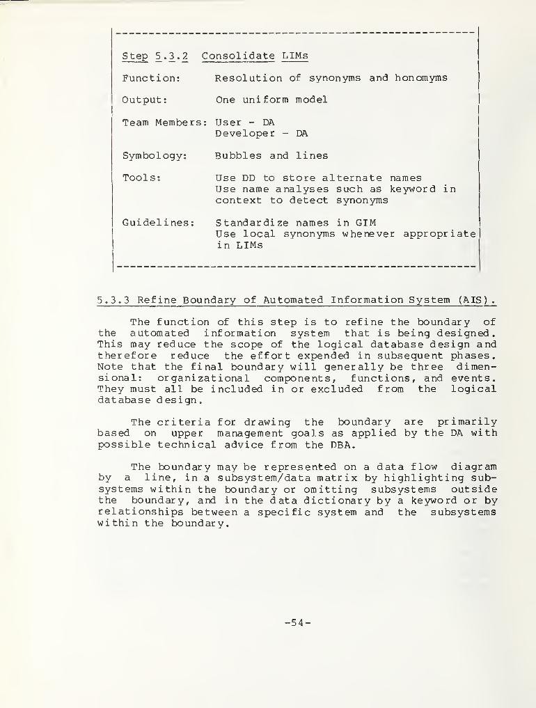
5.3.1 Verify the LIMs 515.3.2 Consolidate LIMs 525.3.3 Refine Boundary of Automated Information
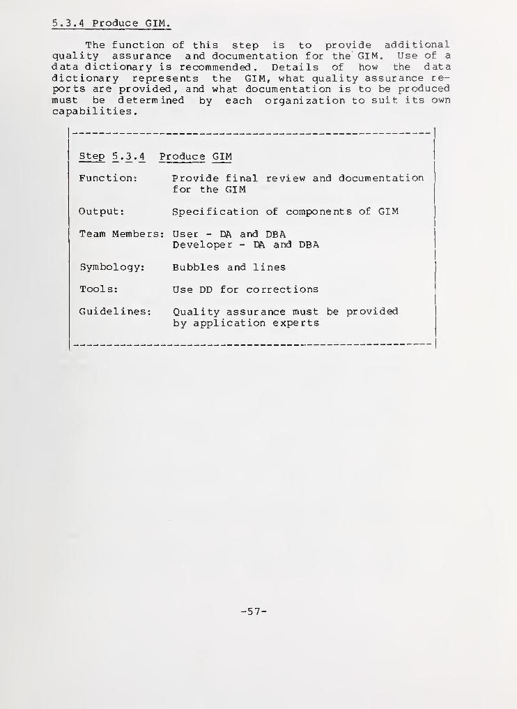
System (AIS) 545.3.4 Produce GIM 57
6. CONCEPTUAL SCHEMA DESIGN 58
6.1 Information Used to Develop the CS 59
6.2 Functions of the CS 59
6.3 Procedure for Developing the CS 60
6.3.1 List Entities and Identifiers 626.3.2 Generate Relationships among Entities 646.3.3 Add Connectivity to Relationships 696.3.4 Add Attributes to Entities 726.3.5 Develop Additional Data Characteristics ... 746.3.6 Normalize the Collection 75
7. EXTERNAL SCHEMA MODELING 77
7.1 Information Used to Develop the ES 77
7.2 Functions of the ES 77
7.3 Procedure for Developing the ES 78
-iv-
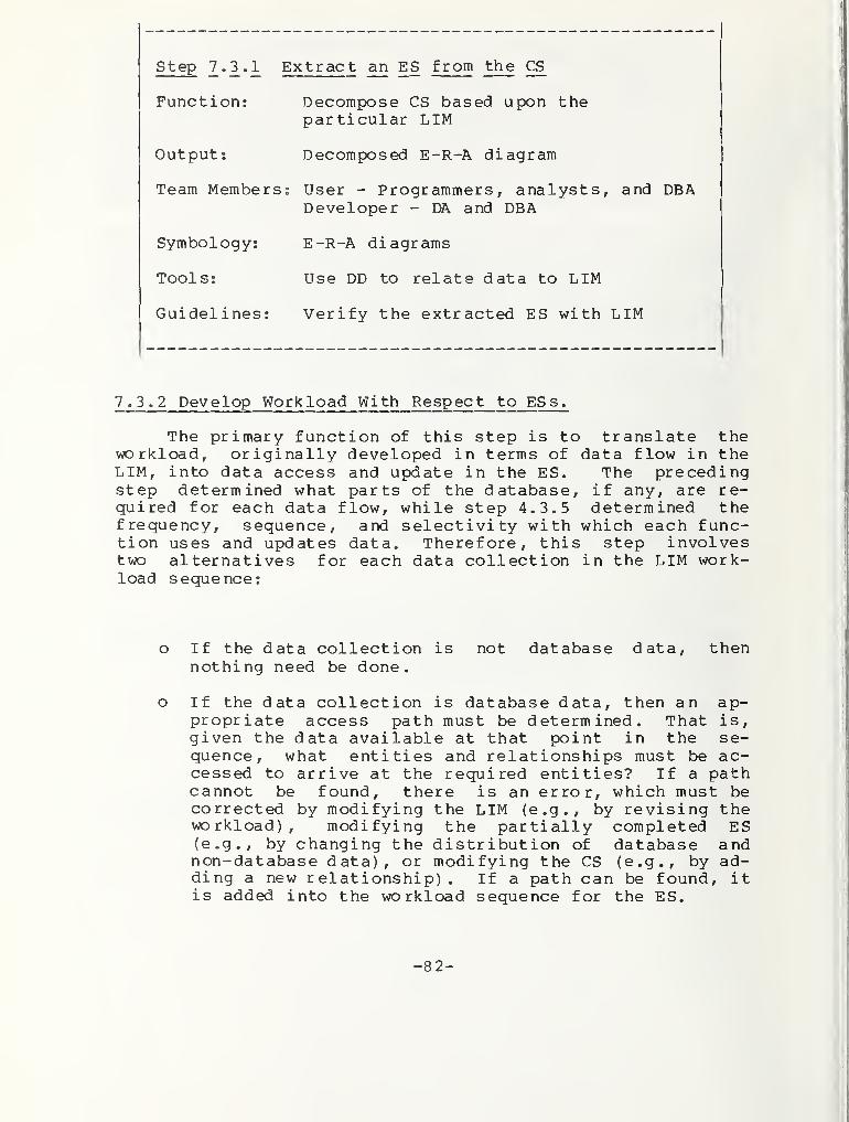
7.3.1 Extract an ES from the CS 80
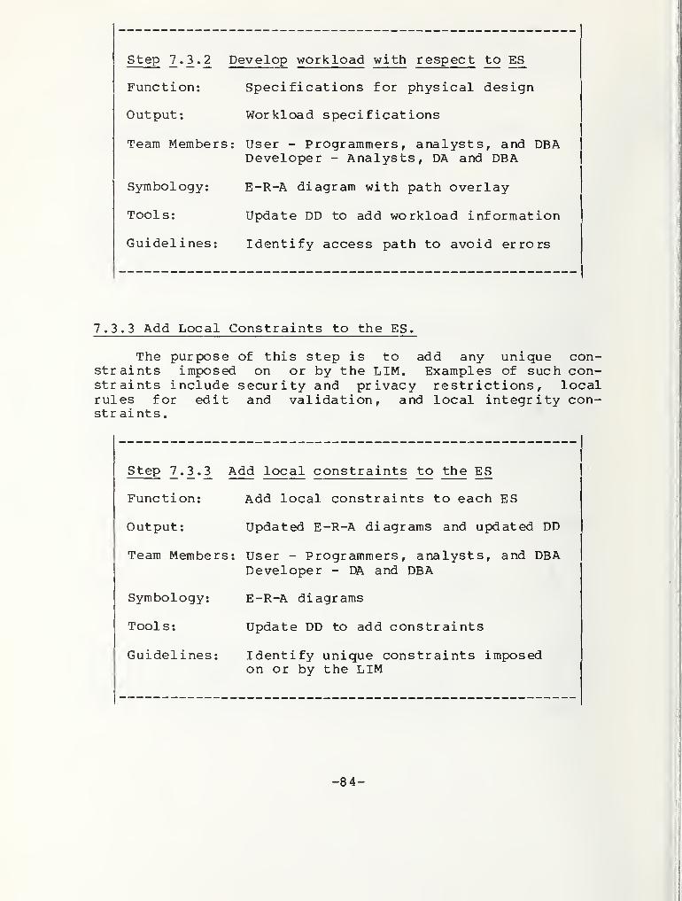
7.3.2 Develop Workload With Respect to ESs 827.3.3 Add Local Constraints to the ES 84
8. CONCLUSIONS 8 5
9. ACKNOWLEDGMENTS 8 6
10. REFERENCES AND SELECTED READINGS 87
-V-
LIST OF FIGURES
FIGURES DESCRIPTION PAGE
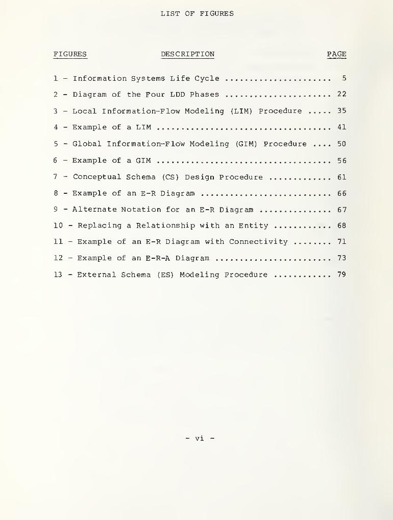
1 - Information Systems Life Cycle 5
2 - Diagram of the Four LDD Phases 22
3 - Local Information-Flow Modeling (LIM) Procedure 35
4 - Example of a LIM 41
5 - Global Information-Flow Modeling (GIM) Procedure .... 50
6 - Example of a GIM , 56
7 - Conceptual Schema (CS) Design Procedure 61
8 - Example of an E-R Diagram 66
9 - Alternate Notation for an E-R Diagram 67
10 - Replacing a Relationship with an Entity 68
11 - Example of an E-R Diagram with Connectivity 71
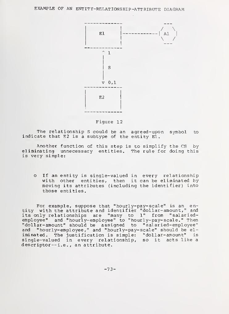
12 - Example of an E-R-A Diagram 73
13 - External Schema (ES) Modeling Procedure 79
- vi -
LIST OF ABBREVIATIONS
AA Application AdministratorAIS Automated Information SystemBSP Business Systems PlanningCS Conceptual SchemaDA Data AdministratorDBA Database AdministratorDBMS Database Management SystemDD Data DictionaryDDA Data Dictionary AdministratorDDS Data Dictionary SystemEKNF Elementary Key Normal FormE-R Entity-RelationshipE-R-A Ent i ty-Relat ionship-A tt r ibuteES External SchemaGIM Global Information-flow ModelIRDS Information Resource Dictionary SystemLDD Logical Database DesignLIM Local Information-flow ModelPERT Program Evaluation and Review TechniqueQA Quality Assurance
- vi i -
Guide on Logical Database Design
Eli zabethMargaret W.
David K.Joan M.
N. FongHenderson
JeffersonSullivan
This report discusses an iterative methodolo-gy for Logical Database Design. The inethodologyincludes four phases: Local Information-flowModeling, Global Information-flow Modeling, Con-ceptual Schema Design, and External Schema Model-ing. These phases are intended to make maximumuse of available information and user expertise,including the use of a previous Needs Analysis,and to prepare a firm foundation for physical da-tabase design and system implementation. Themethodology recommends analysis fran differentpoints of view—organization, function, andevent— in order to ensure that the logical data-base design accurately reflects the requirementsof the entire population of future users. Themethodology also recommends computer support froma data dictionary system, in order to convenientlyand accurately handle the volume and complexity ofdesign documentation and analysis. The reportplaces the methodology in the context of the com-plete system life cycle. An appendix of illustra-tions shows examples of how the four phases of themethodology can be implemented.
Key words: data dictionary system; data dictionarysystem standard; data management; data model; da-tabase design; database management system, DBMS;Entity-Relationship-Attribute Model; InformationResource Dictionary System, IRDS ; logical databasedesign.
-1-
1. INTRODUCTION
1.1 What Is Logical Database Design?
Logical Database Design (LDD) is the process of deter-mining the fundamental data structure needed to support anorganization/ s information resource. LDD provides a struc-ture that determines the way that data is collected, stored,and protected from undesired access. Since data collection,storage, and protection are costly, and since restructuringdata generally requires expensive revisions to programs, itis important that the LDD be of high quality. This guidedescribes procedures that lead to the development of a highquality LDD.
A high quality LDD will be: (1) internally consistent,to reduce the chances of contradictory results from the in-formation system; (2) complete, to ensure that known infor-mation requirements can be satisfied and known constraintscan be enforced; and (3) robust, to allow adaptation of thedata structure in response to foreseeable changes in the in-formation requirements. To fulfill these considerations, agood LDD should be independent of any particular applica-tion, so that all applications can be satisfied, and in-dependent of any particular hardware or software environ-ment, so that the data structure can be supported in any en-vironment. A good LDD will ensure that modularity, effi-ciency, consistency, and integrity are supported in the datastructure underlying the databases of the information sys-tem .
1.1.1 LDD^s Relation to Other Life Cycle Phases.
LDD is closely related to the life cycle phases ofNeeds Analysis, Requirements Analysis, and Physical DatabaseDesign. Needs analysis and requirements analysis providethe information requirements needed to perform LDD. LDDproduces data models and schemas for use in physical data-base design. The Physical Database Design phase receivesthe data structures prepared during LDD and adapts them tothe specific hardware and software environment to form theinternal schema of each database.
-2-
Figure 1 shows LDD's place in the life cycle and dep-icts the functional and data activities that can be per-formed in parallel. LDD can be performed in parallel to thephases of Requirements Analysis, Systems Specification, andSystems Design. The synchronized performance of thesephases will assist in providing the information needed for agood LDD and will result in speeding the systems developmentprocess
.
By taking a brief overview of the development of an in-formation system, we can see how LDD is used. The life cy-cle of an information system should consist of the followingphases
:
1. Needs Analysis
Also known as Enterprise Analysis, this phase is con-ducted before other work on the systems developmentproject begins. Its purpose is to establish the con-text and boundaries of the systems development ef-fort, and provide the focus, scope, priorities, andinitial requirements for the target system.
2. Requirements Analysis
The results of the Needs Analysis are carried furtherin this phase, which provides both the functional andthe data requirements for the system under develop-ment. Requirements analysis is performed in parallelto the LDD and Systems Specification phases. Proto-typing may be performed during this phase to refinerequi rements
.
3. Systems Specification
During this phase, the functional information provid-ed by requirements analysis is used to producespecifications for: input and output reports that areboth external and internal to the system; the func-tions, processes, and procedures of operational sub-systems; and decision support capabilities.
4. Logical Database Design
This phase is performed concurrently with the phasesof Requirements Analysis, Systems Specification, andSystems Design. During this phase, the data require-ments provided by the Needs Analysis and RequirementsAnalysis phases are used to perform the followingiterative data modeling and design activities:
-3-
A. Local and Global Information-flow Modeling
The following are defined: data flows throughoutthe system; information models for each applica-tion (i.e., local) and for the entire system(i.e., global); and, data classifications, re-quirements, and sources for the subsystems in-cluding those for decision support. The LDDdata modeling activities correspond to the func-tional specification activities of to the Sys-tems Specification phase.
B. Conceptual and External Schemas
The following are defined: data structures forsystem-wide (i.e., conceptual) and application-oriented (i.e., external) views of the system;user views of the databases including those pro-viding decision support capabilities; and logi-cal database schema designs and constraints.LDD schema design activities correspond to thefunctional design activities of the SystemsDesign phase.
5. Systems Design
This phase delineates: the functional control flowsusing the data flows from LDD; high level and de-tailed system architectures; the software structuredesign; and the module external design (i.e., thedesign for interfaces among modules of code)
.
6. Physical Database Design
This phase produces physical data flows and the de-tailed internal schema for the specific hardware,software, and database implementations to be used, inorder to balance maximum data storage efficiency,data retrieval performance, and data update perfor-mance. Physical database design is performed inparallel to the Implementation phase.
7. Implementation
This phase produces: logic definition for programs;module design; internal data definitions; coding;testing and debugging; acceptance testing; andconversion from the old system to the new one.
-4-
INFORMATION SYSTEMS LIFE CYCLE
FUNCTIONAL
ACTIVITIES
DATA
ACTIVITIES.
Needs Analysis
Systems Specification RequirementsAnalysis
i
Operation
and Maintenance
LOGICAL DATABASE DESIGN!
Local and Global
Information Modeling
f
Conceptual and External
Schema Design
Physical Database
Design
FIGURE 1
-5-
8, Operation and Maintenance
During this phase the information system performs toserve the users^ information needs and to collectdata about the system's ongoing operation. Program-mers and analysts continue to debug the system andmodify it to support changing users' needs. Databasedesigners continue to maintain database effectivenessand efficiency during system modifications and datachanges. When modifications to the system are nolonger adequate to support user needs, the currentsystem should evolve to a new target system and thecycle will begin again.
As this description of the information system's lifecycle shows, LDD plays a major role in development. LDDgreatly enhances the performance of the Quality Assurance(QA) process, which would be ongoing from the SystemsSpecification and LDD phases through the Operation andMaintenance phase. Because LDD emphasizes the iterative ap-proach, QA will have many opportunities to check the resultsof one iteration against the results of other iterations.Since LDD is performed in parallel to the RequirementsAnalysis, Systems Specification, and Systems Design phases,QA will be able to compare both the interim and finalresults of concurrent phases to resolve any difficultiessooner than through the traditional approach. The automatedData Dictionary System (DDS) , described in Section 1.2.2,should be used during Requirements Analysis and LDD to pro-vide immediate, shared access to data requirements and data-base designs, and to support the QA process.
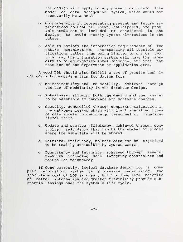
1.1.2 Characteristics of LDD.
The potential benefits of LDD to the development lifecycle can only be gained, however, through a good qualityLDD. For LDD to perform its role well, the results of thelogical design process must have certain characteristics. ALDD should be:
o Independent of the hardware and software environ-ment, so that the design can be implemented in avariety of environments and so the design willremain relevant even if the hardware and softwareselected to support the information system eventual-ly change.
o Independent of the implementation data model or theDatabase Management System (DBMS) in use, so that
-6-
the design will apply to any present or future datamodel or data inanagement system, which would notnecessarily be a DBMS.
o Comprehensive in representing present and future ap-plications so that all known, anticipated, and prob-able needs can be included or considered in thedesign, to avoid costly system alterations in thefuture
.
o Able to satisfy the information requirements of theentire organization, encompassing all possible ap-plications rather than being limited to one or two;this way the information system will have the capa-city to be an organizational resource, not just theresource of one department or application area.
A good LDD should also fulfill a set of precise techni-cal goals to provide a firm foundation for:
o Maintainability and reusability, achieved throughthe use of modularity in the database design.
o Robustness, allowing both the design and the systemto be adaptable to hardware and software changes.
o Security, controlled through compar tmentalization inthe database design which will limit specified typesof data access to designated personnel or organiza-tional units.
o Update and storage efficiency, achieved through con-trolled redundancy that limits the number of placeswhere the same data will be stored.
o Retrieval efficiency, so that data can be organizedto be readily accessible by system users.
o Consistency and integrity, achieved through severalmeasures including data integrity constraints andcontrolled redundancy.
If done correctly, logical database design for a com-plex information system is a massive undertaking. Theshort-term cost of LDD is great, but the long-term benefitsof better information and greater flexibility provide sub-stantial savings over the system's life cycle.
-7-
1.2 An Ideal Logical Database Design Methodology
A methodology is an organized system of practices andprocedures applied to a branch of knowledge to assist in thepursuit of that knowledge, which in this case is databasedesign. In other words, a LDD methodology is a planned ap-proach to database design that assists in database develop-ment in support of an information system.
1.2.1 LDD Practices.
This guide describes a methodology that includes thepreferred practices and procedures characterizing thedevelopment of a good quality LDD and a successful informa-tion system. Although normalization is often considered theprimary activity of LDD, normalization is only one of manyprocedures performed in LDD. Normalization is a valuablebut limited tool in that it only considers functional datadependencies. Other procedures should be used in conjunc-tion with normalization for a coherent database design. Anideal LDD methodology should be supported by:
1. A LDD guide, such as the one provided in this docu-ment, that describes clearly defined steps foranalysts and designers to follow in order to producea good LDD.
2. Analytical methods, such as the ones described inthis guide, to assist in the detection of redundan-cies, incompleteness, and possible errors in the con-ceptual and functional data modeling. Some of thesemethods include: (a) a hierarchical, iterative ap-proach to organizational or functional conceptdevelopment; (b) differentiation of various points ofview in information development, such as organiza-tional components, higher and lower level functions,and event, control, and decision structures; and (c)
normalization procedures.
3. A series of specified checkpoints for progress re-views by designers and management, and for informa-tion exchange meetings with the personnel of LDD^sparallel phases. Requirements Analysis, SystemsSpecification, and Systems Design.
-8-
4. A mode of notation (i.e., graphic or symbolic) todescribe and build a detailed conceptual model of thedata and functions under study.
5. A specification language (e.g., the language used bya Data Dictionary System) to specify information re-quirements and the LDD design in a consistent, unam-biguous manner
.
6. An automated tool such as a Data Dictionary System,capable of supporting the documentation and analysisof LDD complexity, especially for large systemsdevelopment projects. This tool should be used toassist in: (a) describing the conceptual model; (b)
describing the data needed to support the functionsof the conceptual model; (c) performing completenessand consistency checking of the conceptual model andthe data needed to support the functions of the con-ceptual model [AFIF84]
.
1.2.2 Data Dictionary System.
A Data Dictionary System (DDS) is a computer softwaresystem used to record, store, protect, and analyze descrip-tions of an organization's information resources, includingdata and programs. It provides analysts, designers, andmanagers with convenient, controlled access to the summaryand detailed descriptions needed to plan, design, implement,operate, and modify their information systems. The DDS alsoprovides end-users with the data descriptions that they needto formulate ad hoc queries. Equally important, it providesa common language, or framework, for establishing and en-forcing standards and controls throughout an organization.
The data dictionary (DD) is the data that is organizedand managed by the Data Dictionary System. The DD is a
resource that will be of great value long after a logicaldatabase design is completed. The data dictionary can pro-vide support for information about all aspects of systemdevelopment to be stored, updated, and accessed throughoutthe system's life cycle.
The term Information Resource Dictionary System (IRDS)is beginning to replace the term Data Dictionary System dueto recognition of the flexibility and power of the software[ANSI84, FIPS80, KONI84] . This paper uses the terms DataDictionary System (DDS) and data dictionary (DD) to conformto the current practice of software vendors.
-9-
1.3 Intended Audience for this Guide
This guide is intended primarily to provide informationand guidance to: Data Administrators (DAs) and Database Ad-ministrators (DBAs) in leading their LDD projects; Applica-tions Administrators (AAs) and application specialists inthe types of data and data validation that LDD will require;and, end-users and systems analysts in how they can bestcontribute to the LDD project to maximize its benefits.
1.4 Purpose of this Guide
This guide provides a coherent plan of action that willallow management and database designers to direct and per-form the database design successfully. The LDD plan offeredhere is sufficiently general to be compatible with existingtools and techniques in use for database design. By defin-ing a methodology that provides a more stable view of therelationships among data items, this guide can be used toincrease the effectiveness of an inform.ation system over itslife cycle.
When the LDD approach described here is used, particu-larly if used with the assistance of a Data Dictionary Sys-tem, an increase in clear communication can result among theend-users, systems analysts, designers, and the applicationsprogrammers who will actually code and implement the system.By providing a detailed and unambiguous description of thesystem^s information requirements in relation to the users^perspectives, LDD offers a bridge between the end-users andthe physical database designers and applications program-mers.
This guide describes a methodology to be used in optim-izing the flexibility and integrity of an information sys-tem. Flexibility will be ensured through the identificationof the least changing characteristics of the system, whichgive a stable foundation upon which to build the informationsystem. Data integrity will be optimized through the cen-tralized control, completeness, and consistency that a qual-ity LDD will provide. The information system that resultsfrom these LDD procedures will perform better over thesystem's life cycle because it will address current andprobable future needs more completely and will allow re-quirements changes to be incorporated more effectively.
-10-
1.5 Assumptions
Several assumptions have been made in the preparationof this guide about the types of information systems inwhich LDD will be used. Because LDD is a non-trivial pro-cess to be undertaken when a need for it exists, it is as-sumed that:
o The information system''s databases will be sizableand complex to support multiple applications, mayhave no single dominant application, and will prob-ably contain tens or hundreds of data collections andrelationships, and thousands of data elements. DBMSsupport is not assumed, although it is usually desir-able.
o The information system and its databases are intendedfor use over a long period of time so that the bene-fits to the life cycle costs will justify the invest-ment of time, money, and effort in LDD.
o The data requirements of the information system willbe significant and include the use of ad hoc querieswhere the precision of the database structure willprove important.
1.6 Scope of this Guide
This guide is limited in scope to the LDD phase. Theinteraction of LDD with the immediately preceding and subse-quent life cycle phases is mentioned, since these determineLDD^s information resources and products. Because LDD worksfrom the results of the preceding Needs Analysis and con-current Requirements Analysis phases, and prepares a founda-tion for the subsequent Physical Database Design phase,these phases will be described briefly.
-11-
1.7 Structure of this Guide
Chapter 2 addresses the relationship between LDD andthe phases of Needs Analysis, Requirements Analysis, andPhysical Database Design. The major phases of the LDD ap-proach are further discussed along with the types ofanalysis strategies that will be needed to accompany LDD.Figure 2, in Section 2.2.2, illustrates the interaction ofthe four phases of the LDD methodology to assist the readerin visualizing the LDD process.
In Chapter 3, the organizational aspects of the LDDproject are described, including the key roles in LDDdevelopment, the training required for the personnel inthese roles, and the part played by management in planningfor and monitoring the LDD process.
The following chapters, 4 through 7, define the fourphases of the LDD approach in detail. Chapters 4 through 7
are identically structured so that each chapter has threesections: (1) the first section of each phase discusses theinformation used by that phase, (2) the second sectiondiscusses the general functions of that phase, and (3) thethird section discusses the procedure for accomplishing thatphase. The third section of each phase includes a diagramof the steps within that phase, followed by a subsection oneach step. Each step is followed by a summary chart.
Chapter 4 discusses Local Information- flow Modeling anddescribes three modes of analysis corresponding to the tar-get system's (1) organizational components, (2) functions,and (3) the events to which the target information systemwill respond. These three analysis modes are examined inrelation to data flow and data structure design techniques.
Chapter 5 addresses Global Information-flow Modelingand emphasizes the need to balance the perspectives of dataflow and data structure in the development of a design thatwill favor both equally. The Conceptual Schema Design isdescribed in Chapter 6 in relation to the use of Entity-Relationship-Attribute (E-R-A) data modeling diagrams andnormalization techniques. Chapter 7 defines External SchemaModeling (i.e., subschema modeling) as it reflects the datastructure and data flow from the end-user's perspective inthe development of workload specifications for physical da-tabase design.
-12-
A glossary of acronyms used in this guide is includedat the beginning of the document for reference. An appendixof examples has been included at the end of the document toillustrate the types of graphics that will be used andanalysis that will occur during the four phases of LDD.
-13-
2. THE FRAMEWORK THAT SUPPORTS LDD
LDD plays an important part in the life cycle of theinformation system. This chapter describes: (1) the rela-tionship between the database design and the functioning ofthe information system; (2) the interactions between LDD andthe Needs Analysis, Requirements Analysis, and Physical Da-tabase Design phases; (3) the information requirements need-ed to perform LDD; (4) the phases within LDD; and (5) stra-tegies for LDD development and their impact.
2.1 The Role of LDD in the Life Cyclej
J
LDD defines the data structure that supports the data-|bases of an information system. The database system and the
information system are inextricably linked, but they aredifferent. ;
•I
An information system is one or more multi-purpose com- i
puter systems that may be supported by a network throughj
which many types of users, perhaps in different locations, ]
update, query, and provide data to the system in order toj
have current information available on a variety of topics.|
Decision support capabilities may be incorporated in the in-(|
formation system's structure to assist end-users in thedecision-making process.
i
A database is a component of an information system andj
may contain a variety of general and detailed informationj
that is made available to the information system's end-users n
through queries. The information system's ability torespond to user's queries is directly related to logical da- i
tabase design.|
The design of the information system's databases will]
determine the ways in which the information system will i
function. If the information system will be required to|
answer ad hoc queries, the data structures within the data-]
bases should be modeled to provide maximum flexibility inj
data accessibility and retrieval. If the system will be re-jquired to respond quickly to certain predefined queries,
then the structural modeling should be constructed to sup- •
port rapid retrieval performance, which will generally re-quire indexes or redundant data. If the time and expenseneeded to update the data in the system are of paramount im-portance, then ease in locating and changing data values
-14-
should be stressed in the database design. If the storagecost of large databases is a primary consideration, then theminimization of physical redundancy should be emphasized inthe database design.
Usually a combination of such requirements exist for aninformation system, with conflicting implications for thedesign of the underlying databases. These requirements andtheir implications for the databases that support the infor-mation system are defined during the LDD phase, and theirconflicts are resolved during the Physical Database Designph as e
.
The structure of the logical design of the databaseplays a crucial role in determining the capabilities andperformance of an information system. A good physical data-base design cannot be developed without adequate prepara-tion. A good logical database design prepares the ground-work for a quality physical database design and a successfulsystem implementation.
The phases of Needs Analysis, Requirements Analysis,Logical Database Design, and Physical Database Design areclosely linked. The ability to perform the subsequentphases is determined by the performance of the previous andparallel phases. Each of these phases must be performedwell for the resulting database to represent the desiredsystem accurately. These phases are described below.
2.1.1 Needs Analysis.
As we have seen in Chapter 1, a Needs Analysisdescribes the primary needs a new information system shouldfulfill. Without this formal expression of theorganization's perception of its needs, the analysts anddesigners will have to work from their own assumptions of
the information system's purposes. Their assumptions couldunknowingly conflict with the organization's vaguelydescribed or unstated purposes. The resulting lack of clar-ity in direction would be costly.
A specific Needs Analysis methodology should be adoptedand used by an organization previous to undertaking any ex-tensive systems development project. The use of a well-defined methodology assures that most, if not all, of theimportant questions about the purpose of the proposed systemwill have been asked and answered at the end of the NeedsAnalysis phase. One of the most familiar and extensivelyused Needs Analysis methodologies available at this time is
IBM's Business Systems Planning (BSP) approach [MART82].
-15-
In the Needs Analysis methodology adopted, the follow-ing minimum set of questions should be posed:
1. What organizational problems require a solution thatthe target information system could effect?
2. What new or improved information is needed to performwhat types of functions?
3. What are the boundaries and interfaces of the targetsystem?
4. What possible improvements in information availabili-ty could be expected from the target information sys-tem? The following are goals of many system develop-ment projects:
o Greater accuracy of information,o Improved timeliness,o Better end-user interfaces,o Improved privacy and security,o Rapid access to distant information centers
by information sources and end-users.
Once a Needs Analysis methodology has been adopted andthese types of questions have been answered in detail, thepurposes and plans for the systems development project canbe made available to the systems development personnel. Ifthe Needs Analysis has been performed well and a comprehen-sive methodology has been used, sufficient information hasprobably been collected for LDD to begin. Close coordina-tion with the Requirements Analysis phase is needed for LDDto continue.
2.1.2 Requirements Analysis.
The requirements analysis effort will verify and sup-plement the results of the Needs Analysis phase. Since LDDand Systems Specification are directly supported by the con-current Requirements Analysis phase, it is critical that theprocedures and performance of requirements analysis beplanned carefully to coordinate with these other phases.
The Requirements Analysis phase will involve two typesof analysis: (1) analysis of the types of data and dataflows needed within the organization; and (2) analysis ofthe functions performed within the organization which will
-16-
require the use of this data. The purpose of requirementsanalysis is to provide data requirements to support the LDDphase, and functional requirements to support the SystemsSpecification phase.
Requirements analysts verify which functions and sub-systems will remain external to the system, and require in-terfaces. By defining the information products of externalsubsystems or systems that are inputs to the target system,and by defining the information products of the target sys-tem that are used by external subsystems or systems, theanalysts can designate the high level input/output transfor-mations of information that must take place within the tar-get system. The specific functions and subfunctions per-formed within the target system are logically organized anddescribed. Further, the analysts define the known con-straints on accuracy, timeliness, and other performance re-quirements, which will be further defined in LDD. Once gen-eral requirements have been described, further refinementsof the requirements are developed. Prototyping may be usedin conjunction with the LDD and Systems Specification phasesto refine and model requirements.
As requirements are defined, the information may bestored in the form of a data dictionary to be manipulated bya Data Dictionary System. The use of a DDS will provide au-tomated support for the storage, analysis and querying ofdata, for the definition and presentation of technical andmanagement reports, and for the simultaneous access of re-quirements information for use in concurrent phases. Re-quirements information stored in a data dictionary can besupplemented with information from LDD and other phases, andcan be maintained for on-line use throughout the system^slife cycle.
2.1.3 Logical Database Design.
The LDD designers decide which data must be stored andmaintained to support the functions and subfunctions of thetarget system. By abstracting from the functions to thedata structures, the designer defines the data objects to bemodeled and decides which properties and constraints arerelevant in modeling these objects. The Conceptual Schemais the primary product of LDD.
The Entity-Relationship-Attribute modeling techniquehas been chosen to define the LDD data structure (seeChapter 6) . Organizations that prefer other equivalent datamodeling techniques may easily adapt this LDD methodology tothose techniques.
-17-
An important consideration for LDD is to ensure thatall information required from the LDD phase is developed andprovided to the Physical Database Design phase at the ap-propriate time. This information required from LDD includesthe volume of data, the priority and frequency of the logi-cal access paths to be implemented in the physical database,and constraints on performance, integrity, security, andpr ivacy
.
2.1.4 Physical Database Desig n.
The first step of the Physical Database Design phase isto select the appropriate data model (e.g., relational, net-work, or hierarchical) and the data management system tosupport it. This selection may, unfortunately, be dictatedby the software that the organization is currently using, orby the availability of software for hardware that has al-ready been procured. Preferably, the data model and thedata management system will be selected to match the re-quirements defined by the LDD Conceptual Schema and theworkload. A useful reference in the selection process is[GALLS 4]
.
The second step, once the selection has been made, isto translate the Entity-Relationship-Attribute model fromthe Conceptual Schema into the selected data model. Thistranslation is a rather simple matter for the relationalmodel: entities become tables, relationships are implementedby means of foreign keys, and attributes become columns.The network model translation is not much more difficult:entities become records, relationships become sets or re-peating groups, attributes become data items, and attributesare omitted from a member record if they are in the owner.The hierarchical model is difficult: entities becomerecords, attributes become data items, but relationships maybecome either true hierarchical relationships or logicalchildren. These translations are discussed in detail in[CHEN82] and papers referenced therein.
The next step is to develop a detailed physical datastructure, including the development of indexes and otheraccess paths, detailed record structures (perhaps combiningthe logical records to reduce physical accesses), loadingfactors, and so on. Detailed methodologies are discussed in[CARLS 0, CARLS 1, MARC7 8].
-18-
2.2 Detailed Framework for LDD
The information requirements needed for the performanceof LDD are described in Section 2.2.1. Although LDD haspreviously been presented as a single phase within the in-formation system life cycle, in Section 2.2.2 LDD will nowbe subdivided into four simpler phases to be performediteratively. Strategies for analysis and the informationrequirements of these phases will be described in detail inSection 2.2.3.
2.2.1 LDD Information Requirements.
In addition to information obtained from NeedsAnalysis, LDD designers will need other information to becollected and analyzed during the Requirements Analysisphase, conducted in parallel to LDD and Systems Specifica-tion. The following information must be available to LDDdesigners:
o Predefined constraints on the system, such as the useof existing hardware or software, the need to convertan existing system, and the scope of the projectedinformation system.
o Project constraints, such as the amount of time, mo-ney and personnel allocated by the organization forthe development project.
o Processing requirements, such as the type of func-tions that the information system will be expected toperform, and the general application areas that itwill be expected to support.
o Organizational, functional and data subsets, such as
departments, types of actions, and types of informa-tion that the target system will be expected to sup-ply or support.
o Performance requirements, such as maximum retrievaland update times.
o Capacity requirements, such as the number of data ob-jects within the target system, and storage restric-tions if the limitations of existing hardware are ap-plicable.
-19-
o Data integrity requirements, such as the controlneeded over redundant data, and the need for automat-ed integrity checks during data input and update, in-cluding edit and validation rules.
o Security and privacy requirements, such as the needfor encryption for some types of data, or the limita-tion of access for certain types of data to specificpersonnel
.
o Reliability and maintainability requirements that de-fine the need for the continuous functioning of thesystem
.
o Distributed processing and data requirements, such asthe need for network connections among databases inmultiple locations, or the need for shared or repli-cated data in multiple locations.
2.2.2 LDP Phases.
As we have seen from Chapter 1, LDD generally involvesinformation modeling and database design that are largelyhardware and software independent. LDD focuses attention onthe subsystems that generate the information comprising thetarget system. Throughout the phases of LDD, each subsystemis examined and described in terms of: (1) the organization-al components, (2) the application areas or functions, and(3) the events, which occur within or affect that subsystem.The number and type of these subsystems to be analyzed dur-ing each phase of LDD will depend on the type of analysisstrategy selected, as described in Section 2.2.3.
LDD consists of four distinct phases during which allthe subsystems within the system, the data flows, datastructures, and user views of the databases are described.These phases are performed iteratively and in sequence untilthe LDD is completed. The phases of LDD are the subject ofthis paper and are described more fully beginning at Chapter4. In brief, the four phases of LDD are:
1. Local Information-flow Modeling
During this phase, data flows are modeled for indivi-dual subsystems within the target system, includingeach organizational component, function, and event.Subsystems are modeled one at a time. A data flow is
-20-
the information that is exchanged, or "flows," withinand between subsystems. Data is defined at a generalrather than specific level, in terms of general for-mats or packages (e.g., all the data contained withina particular type of report). The products of thisphase are Local Information-flow Models (LIMs)
.
2. Global Information-flow Modeling
During this phase, individual data flows are combinedand global data flows are modeled for collections ofindividual subsystems (i.e., organizational com-ponents, applications, or events) viewed as a whole.Data will continue to be viewed at the format orpackage level. The products of this phase are GlobalInformation-flow Models (GIMs) .
3. Conceptual Schema Design
During this phase, the data within the data flows,defined in the previous phases, is abstracted fromthe packages in which it resides, and defined interms of its functional use. The data is describedin terms of: (a) entities, the basic data components;(b) relationships, the ways in which entities are as-sociated with each other or share characteristics;and (c) attributes, the data that describes the dataentities. Entity-Relationship-Attribute (E-R-A) di-agrams may be used as an analysis method. The E-R-Aabstraction provides the basis for a conceptual datastructure. The products of this phase are ConceptualSchemas (CSs) .
4. External Schema Modeling
During this phase, the conceptual schema is adaptedto conform to the needs of the application areaswithin the information system. By modeling the datafrom the user's perspective, the designer is able toverify the Conceptual Schema and derive a structureduser'*s view of the data. The products of this phaseare External Schemas (ESs) and are also known assubschemas
.
Figure 2 depicts the iterative relationship of the four>D phases. The vertical line through the center indicatesdivision between the phases on the left that are oriented
-21-
DIAGRAM OF THE FOUR LDD PHASES
FROMNEEDS ANALYSIS
ANDREQUIREMENTS ANALYSIS
Specific Application General Interest
Process—oriented
Data Flow
Data Structure
(shared^ static)
LOCAL INFORHATIOH
FLOU nOOEL
COMBINE'GLOBAL INFORMATION
FLOW HODEL
TOPHYSICAL DATABASE DESIGN
(INTERNAL SCHEMA)
FIGURE 2
-22-
toward a specific application (e.g., toward one organiza-tional component, function, or event), and those phases onthe right that are oriented toward organizing these specificapplications into areas of general interest.
The horizontal line across the diagram indicates adivision between the upper phases that are oriented towardthe performance of functions and the dynamic data flow amongthese functions, and the lower phases that are oriented to-ward relatively static, shared data structures.
At the top of the diagram. Needs Analysis and Require-ments Analysis indicates that these phases provide informa-tion to LDD. The results of Needs Analysis may be suffi-cient to begin the initial iterations of the LIM and GIMphases, particularly if the Business Systems Planning (BSP)methodology has been used. Subsequent iterations will re-quire further information from the Requirements Analysisphase.
The diagram in Figure 2 should be read clockwise, be-ginning at Local Information- flow Modeling (LIM) , where dataflows are modeled. In Global Information-flow Modeling(GIM), the individual data flows from LIM are combined intoglobal data flows. These are abstracted to the underlyingshared entities, relationships and attributes in the Concep-tual Schema (CS) . Parts of the CS are then extracted toform each External Schema (ES) , which is a particular user'sview of the shared data. At this point, each ES is thencompared with the appropriate, previously developed LIM, toensure that the data required by the LIM has been includedin the ES view. When errors are detected in this comparis-on, the ES, and possibly the CS , will require modification.The workload data that was originally developed for the LIMis translated into operations on data in the ES. Finally,the workload data and the CS are passed on to the next lifecycle phase. Physical Database Design, for the developmentof the internal schema.
2.2.3 Strategies for LDD Development.
Several analysis strategies are possible in approachingLDD. The choice of the strategy will depend on the type ofsystem to be developed and the definition of the data thatwill need to be integrated in its design. The scope of thedata can be described as horizontal and the level of detailas vertical. The system can be viewed horizontally in thebreadth of functions that the information system will sup-port. If the system will provide many functions to many
-2 3-
departments or locations, then the system and its data willhave a broad, horizontal scope. If the system performs fewfunctions but performs them in great detail, then the systemand its data will have a depth of detail. A large systemwill generally include both a breadth of scope and a depthof detail. Three possible strategies for approaching thelogical design phases are described, with their ramifica-tions for system development success. Refer to Figure 2 infollowing the sequence of LDD procedures for the followingstrategies. The three strategies for approaching LDD are:
1. Breadth First.
In this strategy, a large number of LocalInformation-flow Models (LIMs) will be developed atfirst, but in limited detail. The LIMs will then beconsolidated into one Global I nformat ion- f low Model(GIM) with a broad scope but limited detail. One ormore Conceptual Schemas (CSs) will be developed withbroad scope but limited detail. The External Schemas(ESs) extracted from the CS will provide quality con-trol and structure for the next iteration of LIM.The LDD phases will be repeated for the various sub-systems, adding greater detail for each LIM, untilthe data element level is reached. This strategy isanalogous to top-down system design.
Impac t; This strategy is appropriate for the develop-ment of very large, very complex information systems,where a great depth and breadth of data must be in-tegrated through the development process.
2. Depth First
.
In this strategy, a small number of LIMs will bedeveloped through iterations of the LDD phases to thedata element level. The LIMs will be consolidatedinto a GIM having depth of detail but a limited hor-izontal scope. A small number of ESs will bedeveloped, again with depth of detail but limitedscope. Further iterations of the entire process aredeveloped until the desired horizontal scope is at-tai ned
.
Impact: This strategy is inappropriate for thedevelopment of an information system that requiresthe integration of design components of considerablescope and many levels of detail. The use of thisstrategy may result in the need to redesign the sys-tem to effect integration. This strategy is
-24-
appropriate only for the development of throw- away orexpendable training or prototype projects, such as aprototype system used to verify a development con-cept, or an experimental system used to train person-nel in other systems development concepts or in DataDictionary System use.
3. Critical Factors First.
In this strategy, a large number of LIMs aredeveloped, including details for the critical aspectsof the target system (e.g., critical functional re-quirements, critical performance characteristics,proof of concept, etc.). The LIMs will be consoli-dated into a GIM with broad scope but uneven detail.One or more CSs will be developed with the same broadscope but uneven levels of detail. The process willbe repeated with increasing levels of detail for eachLIM, with subsystems analyzed in order of priority,until the data element level is reached. The criti-cal subsystems will be processed through the LDD cy-cle first, and the non-critical subsystems will fol-low later
.
Impac t; This strategy is appropriate for the develop-ment of a very large system if the critical factorsof the target system can be identified and accepted.It is also appropriate for prototype development andfor evolutionary development, where some functionswill be implemented first and other functions willfollow.
2.2.4 Summary of LDD Features .
The four phases of LDD use a variety of symbologies toassist in analysis. These include the use of bubble di-agrams in the analysis of data flows, Entity-Relationship-Attribute (E-R-A) diagrams in CS development, normalizationanalyses where applicable, and Data Dictionary System (DDS)
contents and automated analysis reports throughout LDD.
The outputs of LDD's phases are: Local Information-flowModels (LIMs) and Global Information-flow Models (GIMs) thatmodel data flows for the organizational components, func-tions, and events; Conceptual Schemas (CSs) that provide anE-R-A model, or another type of data model, for use by pro-grammers and designers; and External Schemas (ESs) thatpresent an application-oriented user view for use within theorganization as a representation of the data to be includedin the target system.
-25-
3. PROJECT ORGANIZATION
For LDD to be performed successfully, plans should bemade to support the information requirements of LDD and toincorporate LDD roles into the organization. In thischapter, LDD functional roles, training, and project plan-ning needs are described.
3.1 Functional Roles Needed for LDD
The following functional roles are described in termsof the development of LDD. A role may be performed by manypeople, or one person may perform several roles, dependingon the complexity of the database. Some LDD roles may over-lap with roles to be performed in Requirements Analysis andother phases. The roles required for LDD are the following:
o Application Administrators (AAs) who will work withdesigners and analysts to define and validate thedata and functions. One or more AAs may be neededaccording to the size of the system and the complexi-ty of the application areas. AAs will work with anumber of application specialists,
o Application Specialists who are knowledgeable aboutthe application data being modeled, or about the ap-plication functions that use the data, or about both.The application specialists will assist the designersand analysts in preparing an accurate LDD.
o Data Administrator (DA) who will facilitate the LDDand systems development process by ensuring con-sistency in data definition, and overseeing the datamanagement, data integrity, and data security func-tions performed in LDD development. The DA will con-tinue to perform this role in regulating these facetsof the information system once it is completed, andso will also use the LDD once it is developed. TheDA may have a sizable staff, depending on the com-plexity of the data resource and the time availableto perform LDD and other tasks. The DA staff may in-clude the Database Administrator and the Data Dic-tionary Administrator. The DA staff will work close-ly with the AAs.
-26-
Database Administrator (DBA) who will control the da-tabase and the DBMS, facilitate the LDD and systemsdevelopment process, assist in data maintenance, anduse the LDD as it is developed. The DBA is concernedprimarily with technical aspects of the database, incontrast to the DA, who is more concerned with infor-mation pxDlicy and interacts with management andusers. The DBA will continue in this role once theinformation system is operational. The DBA may havea small staff to support this function. This func-tion will continue throughout the life cycle of thetarget system.
Data Dictionary Administrator (DDA) who will overseethe operation of the Data Dictionary System (DDS)
,
and assist in the data maintenance process for LDD.The DDA may be supported by a staff, including a Li-brarian and possibly data entry personnel. Data en-try may also be performed directly by designers andanalysts in the course of their work. The DDA func-tion should continue throughout the life cycle of thetarget system, to continue to maintain documentationabout the system.
Data Dictionary Librarian who will maintain the datain the data dictionary (DD) , and support the LDD andsystems development effort.
Database Designers/Analysts who will develop the in-formation requirements, logical database diagrams,models and schemas. They will be expert in databasedesign, familiar with the DDS, and become familiarwith the application areas. They will perform thefunctions that are the focus of this report. Data-base designers will be needed throughout the life cy-cle of the information system, to maintain high per-formance and efficiency as the database changesthrough time.
Project Managers who will direct the LDD and systemsdevelopment projects. They will be familiar with theapplication areas, computer systems, systems develop-ment practices, and become familiar with LDD pro-cedures .
End-users of the DDS and the information system underdevelopment who will access and update information inthe databases, and who will generate reports and de-cisions from this information. End-users will in-clude personnel from all organizational levels andwill perform the following roles:
-27-
Data Entry and Update
Data Retrieval
- Data Analysis
Data Management and Control
- Project Management
- Upper Management
3.2 Training Required for LDD
The personnel involved in the LDD phase of development,particularly AAs and Application Specialists, will requiretraining so that they will be able to work with databasedesigners as a team. Some personnel will already beknowledgeable in these areas, but many will need to betrained. Project management should arrange to have LDD per-sonnel trained in:
o The purpose and general procedures of LDD.
o The points of view to be represented within the sys-tem (i.e., organizational components, functions, andevents) .
o Use of the symbology, such as how to construct andinterpret E-R-A and bubble diagrams.
o Use of the Data Dictionary System or other automatedtool
.
End-users who review the LDD may require any of threelevels of training in the use of the Data Dictionary System,depending on the extent of each end-user's responsibility:
o Reading knowledge of LDD reports that are generatedvia the DDS , to be able to recognize when the reportindicates a modeling error.
-28-
o Interpretive capability to understand LDD reportsgenerated via the DDS , to be able to recognize whatis wrong in a report that indicates a modeling error.
o Expert knowledge of the DDS procedures and an under-standing of the products of LDD, to be able tocorrect errors in modeling detected in DDS reports.
3.3 Project Planning and Management Requirements
The systems development Project Manager and the LDDManager should plan for and control the systems developmentproject so that a high quality LDD results. In addition tothe activities of traditional management roles, managers inthese positions must determine that several procedures havebeen adopted before the project begins.
The Project Manager must be sure that good methodolo-gies have been selected or developed for the Needs Analysis,Requirements Analysis, LDD, and other phases. In addition,it is necessary to determine that these methodologies arecoordinated according to a schedule so that the results ofprevious and parallel phases are available for use by otherphases. The schedule should also include various types oftraining for personnel working on parallel phases. Further,the Project Manager must decide on a strategy for LDDdevelopment that will support the breadth of scope and depthof detail to be encountered in analyzing the target system.
The Logical Database Design Manager will fill a similarrole for the LDD phase. The LDD Manager will: (1) select agood LDD methodology and analysis strategy suitable to thetype of system under development; (2) coordinate LDD train-ing with the managers for parallel phases; (3) coordinateLDD activities with the Requirements Analysis Manager, sothat information will be available for LDD to conform to ap-propriate schedules; (4) define checkpoints to review theprogress of the LDD work; (5) determine the types andcharacteristics of the DDS documentation and analysis re-ports to be generated to support the LDD phases; and (6)
manage the synthesis and integration of information frommany sources within the organization to support LDD.
-29-
4. LOCAL IN FORMAT ION -FLOW MODELING
A Local Information-flow Model (LIM) is a descriptionof the movement of data collections such as reports, forms,memos, messages, transactions, and files to, from, andwithin a particular focal point. The focal point may be anorganizational component (e.g., the personnel department), afunction or application (e.g., payroll processing), or anevent (e.g., a milestone in the budget cycle). The firstiteration of this phase will produce a single LIM summariz-ing the inputs and outputs of the entire organization servedby the database being designed. During subsequent itera-tions multiple LIMs will be produced, each describing a partof the next higher-level LIM. The level of detail may bevery high (e.g., very general types of data going into orout of an entire organization), intermediate (e.g., reportsand other data going into, out of, or processed within anoffice), or very low (e.g., transformation of an employeenumber into an employee name) , depending on the number ofiterations through the four phases of logical databasedesign.
There are two reasons for choosing this approach:
1. Complexity is controlled at every stage of the itera-tion by restricting the scope of each LIM. Inter-views with users can concentrate on the most criticalaspects of the user^s organization, function, orevent, with the assurance that a higher-level contexthas already been developed and that details can befilled in later. The interviewer need not beoverwhelmed with trying to understand everything allat once. Note that a top-down approach isadvisable— starting from data elements and working upis more likely to end in a disastrous lack of direc-tion and an abundance of confusion.
2. The different aspects—organization, function, andevent— represent the fact that organizational struc-tures are important, but they do not give a completemodel of information processing. Functions andresponsibilities are shared by sequential or simul-taneous access to and transformation of data. Allaspects may be required to give a true picture of da-tabase requirements. Note that manual functionsshould be analyzed if there is a significant chancethat they will be automated during the life of thed at abas e
.
-30-
The general objective is for a LIM to represent whatev-er an application specialist knows about his or her job andorganization. The LIM does not represent details about howinformation is captured or derived before it reaches the ap-plication specialist or how it is used or processed after itleaves her or him.
The emphasis of the LIM should be on business functionsand events— that is, data, operations, and products that arebasic to achieving organizational objectives— rather than onany particular technology for implementing those functions.One reason for this particular emphasis is the fact thattechnology changes much more rapidly than the business func-tions (the need for payroll is constant, but the policiesand technologies implementing it are changeable). A data-base should be relatively stable and retain its value over along period of time— the time and cost of data collectionand organization are too great to permit the database to beconsidered anything less than a major capital investment.Another reason for the emphasis on business functions isthat these are familiar and well-understood by the datausers, who are the people responsible for achieving organi-zational objectives. The abstract concepts of data model-ing, introduced in the phase concerned with the developmentof the Conceptual Schema, are generally not meaningful tothe user unless there is some familiar context of businessfunctions. One way of viewing the LIM is that it is a meansfor relating the abstract External Schema (a part of theConceptual Schema) to a concrete business context.
4.1 Information Used to Develop the LIM
Information that is relevant to the development of theLIM may be obtained through examination of documents orthrough interviews, or, preferably, through interviews basedon thorough preparation via documents. The following infor-mation is generally needed:
1. The nature, objectives, structure, and scope of thesubsystem must all be analyzed to ensure compatibleLIMs. Both the present and the future should be con-sidered. Non-routine operations, or operations thatare performed infrequently, may be particularlyimportant— for example, end-of-year accounting opera-tions may have unique but critical requirements. In-teractions with customers, vendors, and other parts
-31-
of the external environment may be very important.
2. Existing automated systems and other availablehardware, software, and data resources should be stu-died to determine how they interact with the subsys-tem being studied; the emphasis should be on thequeries, reports, and transactions that are actuallyrelevant rather than on what is currently produced.It is important to maintain continuity with thepresent while still ensuring sufficient flexibilityfor long term growth of the information resource.Existing systems may already have replaced certainfunctions and as such should themselves be "inter-viewed." This can be difficult since existing systemsmay be poorly structured and documented. However,existing systems have already solved problems — whatare those problems? Existing systems may be enforc-ing policies that the people are no longer aware of— what are those policies? Existing systems mayalso be creating data that everyone takes for granted— how are existing systems combining files, applyingalgorithms, etc.?
3. The subsystem's perspective on decisions must beanalyzed. The position titles and descriptions heldby decision-makers, the business models that theyuse, the information that they require, and the rela-tionships that they have with other decision-makersmust all be analyzed. Senior management views (stra-tegic planning) , middle management views (control andtactical policy), and applications views (operations)are all required to give balance to the total collec-tion of LIMs. Historical and "what if" data are par-ticularly important in analyzing the data flow ofhigher-level decision makers.
4. Real-world rules and policies should be studied.Geographic location requirements are particularly im-portant (e.g., there is little point in designing ahighly integrated central database if the policy isto maintain local control of data) . Policies on dataretention and archiving may also be important (e.g.,archiving may constitute a major information subsys-tem) , Security, privacy, integrity, and error han-dling policies (including policies and procedures forrecovery from both data processing and organizationalmistakes) may have major effects on the data struc-tures (for example, classified and unclassified datamay have to be stored separately)
.
-32-
5. A catalog of reports and forms needed for routinetasks is clearly relevant to the LIM. Collections ofreports and forms are relevant to high-level LIMs,individual reports and forms are relevant tointermediate-level LIMs, and parts of reports andforms are relevant to low-level LIMs. The timelinessand quality of the reports and forms should berecorded. Reports that have outlived their useful-ness are irrelevant to LDD.
6. Collections of informal data are also very important.This data can include files or folders of memos andletters (e.g.. Freedom of Information Act requests,and customer complaints in writing), notes on tele-phone conversations (e.g., payroll inquiries), anddatabases on personal computers.
7. Formal reference data collections such as FIPS codes,ZIP codes, pay scale tables, and address or telephonedirectories are relevant.
8. "Log" books or lists may be used to assign uniquenumbers, organize office functions, record signifi-cant events, or otherwise coordinate activities.
9. Other regular sources of information, such as tele-phone contacts, should be carefully studied, sincethese may be very relevant to getting the job done.
10. Information from the higher-level GIM and thehigher-level LIM which is being subdivided providecontext for developing more detailed LIMs in succes-sive iterations of the LDD cycle. Once LDD has be-gun, the examination of this information will be thefirst step in providing a LIM.
11. Quantitative information on volume of data and fre-quency of processing for all of the above. This in-formation will be used to help develop an estimate ofthe database workload.
Since each LIM is a refinement of the previous itera-tion of the design cycle, the LIM is constrained by the pre-vious higher-level LIM and External Schema. If deeperanalysis uncovers an error at the higher level, then thathigher-level should be corrected before proceeding further.Otherwise, other lower-level LIMs, based on the erroneousLIM and External Schema, may contain errors or be incon-sistent with each other.
-33-
4.2 Functions of the LIM
The primary function of the LIM is to serve as part ofthe Global I nf ormation- f low Model (GIM) . Other functions ofthe LIM are:
1. The LIM provides a guide for the development offurther details. Each iteration is based on a decom-position of a previously developed LIM, unless thefocus is switched from an organizational component toa function or event, in which case the new LIMs arebased on combinations of previously developed LIMs.
2. The LIM may be used as a guide to planning thedevelopment of a new application program or system,modifying an old application program or system, ormodifying the organizational structure. In eachcase, the LIM is analyzed to see whether the flow ofdata is efficient and effective; changes are suggest-ed if unused reports are being produced, if similarfunctions are being performed unnecessarily, if func-tions that should be performed by a computer systemare being performed manually, or if the data flow canbe reduced by combining organizational componentsthat sequentially process the same data.
3. The LIM is also used to collect information concern-ing the database workload. This information is even-tually used to optimize and evaluate the physical da-tabase design.
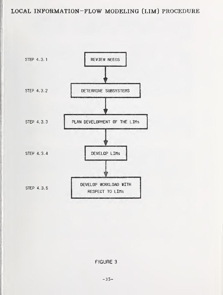
4.3 Procedure for Developing the LIM
Figure 3 shows the five sequential steps in thedevelopment of the LIM. The steps are described in the fol-lowing paragraphs.
-3 4-
LOCAL INFOilMATION-FLOW MODELING [LIM) PROCEDURE
STEP 4. 3.
1
STEP 4.3.2
STEP 4.3.3
STEP 4.3.4
STEP 4,3.5
REVIEW NEEDS
I
IPLAN DEVELOPMENT OF THE LIMs
iDEVELOP LIMs
IDEVELOP WORKLOAD WITH
RESPECT TO LIMs
FIGURE 3
-35-
4.3.1 Review Need for Analysis.
The primary function of this step is to determinewhether the organizational component, function, or eventunder consideration should be subdivided for furtheranalysis, or whether it has already been analyzed suffi-ciently .
The first iteration of the logical database designmethodology will begin with a preliminary determination ofboundaries— that is, which organizational components, func-tions, and events require interaction with the proposed da-tabase. Next, it is necessary to determine the best methodfor subdividing the design problem--by organizational com-ponents, by functions, or by events. Generally, the firstfew subdivisions will be along organizational boundaries.These boundaries are usually well-defined, familiar, andnon-threatening to the application specialists. They servevery well in identifying broad classes of data, major func-tions and events, and data. flows.
Organizational decomposition may be insufficient, how-ever, for the detailed development of data structures whichare shared among different organizational components. Lateriterations should concentrate on subdividing the functionsand events that have been identified during the study of or-ganizational subdivisions; such functions and events mustprovide data to the database and use data from it, so aredirectly relevant to the structure of the database.
Since functions and events frequently cross organiza-tional boundaries, their analysis may suggest the need forreorganization to eliminate duplicate or unnecessary jobs,and will almost certainly require cooperation among applica-tion specialists from different organizational components.Consequently, such analysis is very delicate and should notbe attempted too early in the LDD process.
Eventually it will be determined that there is no needto subdivide any more functions or events; the logical data-base design process is then "complete," although maintenanceof the LIMs and other products must continue indefinitely.
-36-
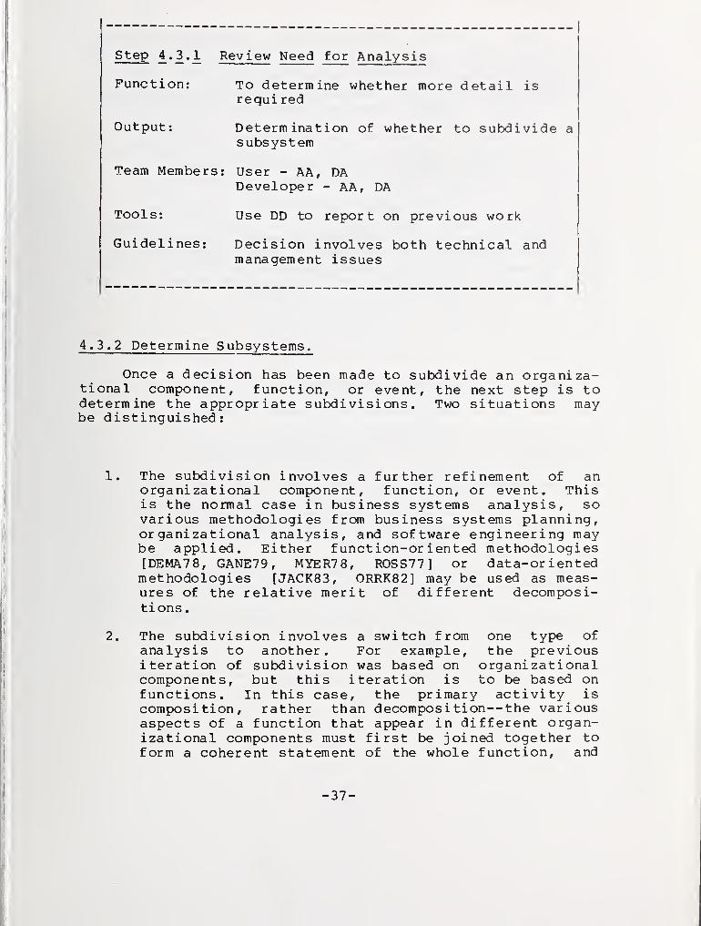
step £.2«2i Review Need for Analysis
Function: To determine whether more detail isre qui red
Output: Determination of whether to subdivide asubsystem
Team Members: User - AA, DADeveloper - AA, DA
Tools: Use DD to report on previous work
Guidelines: Decision involves both technical andmanagement issues
4.3.2 Determine Subsystems.
Once a decision has been made to subdivide an organiza-tional component, function, or event, the next step is todetermine the appropriate subdivisions. Two situations maybe distinguished:
1. The subdivision involves a further refinement of anorganizational component, function, or event. Thisis the normal case in business systems analysis, sovarious methodologies from business systems planning,organizational analysis, and software engineering maybe applied. Either function-oriented methodologies[DEMA78, GANE79, MYER78, ROSS77] or data-orientedmethodologies [JACK83, ORRK82] may be used as meas-ures of the relative merit of different decomposi-tions .
2. The subdivision involves a switch from one type ofanalysis to another. For example, the previousiteration of subdivision was based on organizationalcomponents, but this iteration is to be based onfunctions. In this case, the primary activity iscomposition, rather than decomposition— the variousaspects of a function that appear in different organ-izational components must first be joined together toform a coherent statement of the whole function, and
-37-
i
then functional decomposition can proceed at lateriterations. Clearly, it is extremely important thatdata flow has been carefully documented during previ-ous iterations; data flow is the primary clue to thecommon basis for different organizational perspec-tives on a single function. The effect of a Data Dic-tionary System is to allow the DA to combine an or-ganizational hierarchy, a functional hierarchy, andan event hierarchy into a consistent network whichcan be supported by the database structure.
In either case, the result will be a list of well-defined subsystems—organizational components, functions, orevents— of the LIM being analyzed. The subsequent stepswill determine how each subsystem interacts with the dataflowing into or out of that LIM, and the data flowing fromor to the other subsystems.
Step 4^.2*2 Determine Subsystems
Function: Determination of how to subdivide asubsystem
Tools: Use DD to represent organizationalcomponents, functions, or events
Guidelines: Care is required — poorly chosensubsystems will have overly complexinterfaces
-38-
i
4.3.3 Plan Developinent of the LIM.
This step involves the development of a detailed planfor this iteration of the analysis. The plan may includepriorities, so that decomposition will consider criticalfactors first. Two strategies are possible:
1. Each step in the subdivision spawns a set of indepen-dent plans. Detailed work may proceed in parallel,given a sufficiently large staff, with the resultscoordinated primarily through the data dictionary.The advantage of this approach is that planning isminimized. The disadvantage is that quality controlof the data dictionary becomes extremely criticalduring and after execution of the plan. Synonyms andhomonyms for functions and data must be detected andresolved quickly or different analysis paths willunknowingly overlap, resulting in confusion and du-plication of effort. The philosophy of this strategyis to move quickly and solve problems later (possiblyduring the development of the GIM)
.
2. Each step in the subdivision involves the developmentof a single, coordinated plan. Detailed work iscoordinated in advance, so that problems of synonyms,homonyms, and duplicated effort are minimized. Theadvantage of this approach is that overall control ofthe effort is maintained. The obvious disadvantageis that this approach requires extremely knowledge-able DA and AA staff to formulate, monitor, and con-trol the execution of the plan. Also, more work mustbe done serially rather than in parallel.
In either case, it is necessary to develop a detailedproject management plan, with milestones, time and cost es-timates, and assignments for application specialists as wellas for AA and DA personnel.
-39-
step 4.3.3 Plan Development of the LIM
Function: Develop project management plan forthis subsystem
Output
:
Milestones, time and cost estimates
Team Members: User - AA, DADeveloper - AA, DA, Managers
Symbology: Project management charts
Tools: Use DD to represent project managementdata and boundaries
Guidelines: Assignments must be very specific
4.3.4 Develop LIM.
Various system analysis and design methodologies may beused in conjunction with a data dictionary to document thedata flows that are developed. Either function-orientedmethodologies [DEMA78, GANE79, MYER78, ROSS77 ] or data-oriented methodologies [JACK83, ORRK82] are suitable.Whereas previous steps have involved consultation withmanagement, this step and the following are best accom-plished by short interviews (no more than two hours periteration) with application specialists. Reference materialand the LIM developed during the previous iteration are usedto prepare for the interview and to verify the analyst's in-terpretation of the application specialist's statements.All materials may be made available to the application spe-cialists in advance of the interview. (Note that discrepan-cies revealed during an interview should prompt furtherquestions rather than challenges— the interview should notbe threatening.) Graphical simplicity is very desirable, sothat untrained users can judge the correctness of the LIMsthat are relevant to them.
Useful types of diagrams include the following:
-4 0-
1. An organization chart can be used to show thehierarchical relationships among organizational LIMs.
2. A "bubble" diagram with an organizational focal pointconnected to other organizations by data flows can beused to represent an organizational LIM, as in thefollowing:
EXAMPLE OF A LOCAL IN FORMAT ION-FLOW MODEL
/ ^\
External \Organization
|
\\
Data to
V
//
Data from
/ \/Organizational\
Component l<-
Being|
\ Modeled /\ /
Data from / \/ Second \
IOrganizational
IComponent
\\ /
/
Shared Documents
V
/ \/ Third \Organizational
Componen t
\\ /
/
Figure 4
-41-
3. A functional hierarchy can be used to show the
hierarchical relationships among the functional LIMs.
4. A data-flow diagram [DEMA78, GANE79, MYER78] or ac-tion diagram [ROSS77] can be used to show inputs,outputs, subf unctions , and data flows among the sub-functions of a functional LIM. (Note that this typeof diagram shows two levels of the LIM hierarchy.)
5. A Gantt chart can be used to show the temporal rela-tionships among events.
6. A PERT chart can be used to show the relationships,especially time dependencies, among functions andevents.
7. A state-vector diagram [JACK83] or a decision tablecan be used to show additional details of functionsand events.
The data dictionary is used to record detailed informa-tion that would only confuse a diagram; automated analysisof program code, job control language, and audit trails mayprovide much of the detail. The selectivity of data dic-tionary queries and reports helps to make the detailscomprehensible. Diagrams should be produced automaticallyfrom the data dictionary. Also, graphic input could be a
means of populating the data dictionary when this capabilitybecomes automated in the future.
A special but important example of data flow is storageand retrieval of information by an organizational component,function, or event; the storage medium is treated likeanother organizational component, function, or event.
Data flow is used to determine the formal consistencyand completeness of the analysis— for example, whether eachdata flow has a source and a sink (either may be some inter-nal storage medium) . The use of a data dictionary is ex-tremely important in this situation to ensure that all ofthe various aspects of the function are considered. Theviews of all users who interact with a function must be re-flected in that function.
The description of data flows should generally includeone level of decomposition. For example, if the data flowsin a top-level functional analysis are collections of re-ports, then each data description in the data dictionaryshould include a list of the component reports. At a lower
-42-
level, if the data flows are reports, then their descrip-tions should include subdivisions of the reports— selectedcolumns, or rows between subtotals, or the subtotals them-selves, for example. At a very detailed level, the datadescriptions would be data elements.
Information which is useful in understanding the rela-tive importanfce of the functions and in planning the nextiteration of this phase includes the following:
1. Staff time, in work-years or other convenient unit,expended on performing the function.
2. The number of staff personnel performing the func-tion.
3. The number of locations where the function is per-formed .
4. Whether there is a single step that consumes 80% ormore of the time spent on the function.
Step 4.3.4 Develop LIMs
Function: Provide guidance to the developmentof the GIM and CS
Output: LIMs
Team Members : User - AA, DADeveloper - AA, DBA
Symbology: Use bubbles to represent organizationalcomponents, events, functions, orexternal interfaces. Use lines torepresent data flows.
Tools: Use DD to represent subsystemsand interfaces
Guidelines: Graphical simplicity is desirableUse selectivity of DD reportsShould be easy for users to understandand critique
-43-
4.3.5 Develop Workload With Respect to LIMs.
The primary function of this step is to develop a prel-iminary description of the workload: the frequency, se-quence, and selectivity with which functions use or producedata, and the volume of stored data [JEFF82, SUST84] . Theworkload will be used during the development of the ExternalSchemas to determine whether the Conceptual Schema can sup-port the LIM, and what paths must be taken through the Con-ceptual Schema to obtain the data required by the LIM. Itwill also be used to determine whether certain functionsshould be automated. The workload must be used during thedevelopment of the Internal Schema (physical databasedesign) to determine appropriate physical record structures,record placement in areas, access methods, loading factors,indexes, and other parameters. Accordingly, this step mustbe performed during the most detailed iteration of function-al analysis; it may be performed at earlier steps to provideadditional quality control for the LIMs and Conceptual Sche-ma.
At this phase, the workload is described in terms ofdata collections that may be very different from the logicalrecords that will eventually constitute the final ConceptualSchema. In particular, the level at this phase may be veryhigh (e.g., data objects like "employee," "project," and"part" rather than data elements like " employee- fi rst-name ,
"
"est imated-proj ect-cost ," and "part-quanti ty-in-warehouse"
)
and the grouping of data may be quite arbitrary (e.g., "em-ployee" may include data about skills, projects, and organi-zations associated with the employee) . Eventually thesedata objects will be restructured to form a database, so itis important to be able to map this preliminary workloadinto appropriate paths through that database.
The information to be collected and stored in the datadictionary should include the following:
1. The volume (number of instances) of each data collec-tion (e.g., the number of employees, projects, andpar ts) .
2. The priority of the function (e.g., "an airlinereservation must be confirmed within 20 seconds" and"a marketing analysis on advance reservations must beavailable within 2 hours of a request").
-44-
3. The frequency of execution of the function.
4. The sequence with which data collections are accessedby the function, and the source of the data from in-put or database (e.g., start with "employee," thenaccess "project," then access "project-manager" todetermine who "manages" a given employee).
5. The parts of each data collection that are used todecide whether a given instance of that data collec-tion is relevant (e.g., "employee-name" identifiesthe required "employee" data).
6. For each of the parts of data collection, the numberof relevant instances (e.g., "1").
7. For each relevant data collection accessed by thefunction, the parts that are needed for retrieval bythe function (e.g., "employee-project" is the onlyretrieved part of the "employee" data) . If applica-ble, the preferred order is desirable (e.g., the"employee-project" data is to be sorted by "project-number" ) .
8. The parts of each relevant data collection that areneeded for update by the function (e.g., "employee-hours" is the only updated part of the "employee"data)
.
9. At each point where the function branches, the frac-tion of the time each branch is taken (e.g., 90% ofthe time "employee-project" will be non-null, so"project" will be accessed, and 10% of the time itwill be null so the path will terminate).
Output: LIMs with volume, frequency,sequence, and selectivity
Team Members: User - AA, DBADeveloper - AA, DBA and Analysts
Symbology: LIM diagrams
Tools: Use DD to store workload informationto be used for physical design
Guidelines: Keep the scope limited to a singleappl icat ion
-46-
5. GLOBAL IN FORMAT ION-FLOW MODELING
A Global Inf ormat ion- flow Model (GIM) is basically aninterconnected collection of all of the Local Information-flow Models (LIMs) . Its structure is quite complex: it com-bines up to three hierarchies of LIMs (a hierarchy based onorganizational components, another based on functions, andpossibly another based on events); these must be intercon-nected in terms of data flow, which itself may be a complexnetwork of data objects, as well as other interrelationshipssuch as organizational authority and responsibility. A DataDictionary System (DDS) is strongly recommended to managethe GIM. In an extremely complex situation, where even aDDS is unable to present the mass of information in a mean-ingful way, multiple GIMs may be developed, each represent-ing a major subsystem loosely connected to the other GIMs.Note, in particular, that the GIM, like the LIM, must gen-erally represent both automated and manual data, and bothcurrent and planned functions.
The major task involved in developing the GIM is simplyadding the new details represented by each new LIM. The newLIMs must be verified for consistency with higher-levelLIMs, names must be reconciled with existing names, and thedifferent perspectives (organization, function, and event)must be interrelated. These are basically responsibilitiesof the DA with assistance from the AAs in detecting andresolving potential problems in performance, cost, reliabil-ity, security, and the like. The DA should not requiredirect access to the users.
The GIM may be represented in various forms accordingto the methodology chosen. A diagram may consist of ovalsor rectangles representing the subsystems, and labelledlines representing the data flows. This is a simplesource-sink model which is very useful for communicatingwith users. Other representations of the GIM include manydifferent types of matrices showing the interactions of or-ganizational components, functions, events, and data objectswith each other [MART82i. A data dictionary is recommendedfor the primary means of representation, from which diagramsand matrices can be produced selectively and automatically.Also, the data dictionary is quite suitable for representingdetails that would be very confusing in a diagram or matrix,such as the Local Information-flow Models (LIMs) and theirrelationships with the GIM, the relationships between namesin the GIM and in the LIMs, and details of database work-load .
-47-
Some methodologies dispense with the GIM [NAVA8 2] andbegin the design of the Conceptual Schema with a smallnumber of applications, then add more applications, continu-ally integrating the new applications with the old Conceptu-al Schema. This has the advantage of facilitating quickdevelopment of a prototype, but has the disadvantage of pos-sible major revisions of the Conceptual Schema [JEFF82].The safer procedure is to develop a GIM with careful controlof detail, so that the level of effort is reasonable yet theGIM provides sufficient detail to guide the development of a
relatively stable Conceptual Schema. This procedure is alsolikely to uncover important new interrelationships amongLIMs, such as unexpected interrelationships among organiza-tional components, and dependencies within them.
Note the similarity of the Local Information-flow Modeland Global Information-flow Model development to BusinessSystems planning (BSP) [MART82], which is also based on dataflow. The primary difference, which is extremely important,is that each iteration of the Local Information-flow Modeland Global Information-flow Model is followed by thedevelopment of the Conceptual Schema and External Schemas inthe procedures described in this paper. This cyclical anditerative approach balances the data flow perspective withthe data structure perspective, so that neither will be em-phasized at the expense of the other. BSP, however, em-phasizes the data flow perspective almost to the exclusionof the data structure perspective; high level data objectsare identified, but their relationships and detailed struc-tures must be developed by another methodology.
5.1 Information Used to Develop the GIM
Information that is relevant to the development of theGIM is obtained primarily from the previous iteration of theGIM and the newly developed LIMs. Other types of informa-tion are similar to those used to develop the LIM, exceptthat they are at a higher organizational level.
1. The nature, objectives, and scope of the organizationmust be analyzed to ensure a compatible GIM.
2. The organizational perspective on decisions must bed eterm ined
.
-48-
3.
4.
5.
Organizational rules and policies must be
Reports and forms must be examined.
Available resources must be determined.
a nalyzed
.
5.2 Functions of the GIM
The primary function of the GIM is to guide thedevelopment of the Conceptual Schema. Other functions ofthe GIM are:
1. The GIM provides context for the development of thenext iteration of the LIMs.
2. The GIM, like the LIMs, may assist in managementplanning to increase efficiency; the GIM provides awider perspective on reducing data flow throughchanges in functions and organizational structures.
3. The GIM may also be used to design the interfacesamong separate, loosely connected Conceptual Schemas,as may be appropriate among several large systems ora distributed database system.
5.3 Procedure for Developing the GIM
Figure 5 shows the four sequential steps in thedevelopment of the GIM. The steps are described in the fol-lowing paragraphs.
-49-
GLOBAL INFORMATION-FLOW MODELING [GIM) PROCEDURE
STEP 5.3. 1
STEP 5.3.2
STEP 5.3.3
STEP 5.3.4
VERIFY THE LIMs
CONSOLIDATE Lins
IREFINE BOUNDARY OF AUTOMATED
INFORMATION SYSTEMS
IPRODUCE GIM
FIGURE 5
-50"
5.3.1 Verify the LIMs.
The LIMs are organized into a hierachy of organization-al components, a separate but interrelated hierarchy offunctions, and, possibly^ a separate but interrelated hiera-chy of events. The function of this step is to verify thateach new LIM is consistent with the objectives and con-straints of the next higher level LIM in its hierarchy. Anyinconsistencies require modification of either the lower-level LIM or the higher-level LIM. In the latter case,modifications may propagate all the way up the hierarchy andpossibly affect the other hierarchies as well: such modifi-cations may also propagate to the GIM, Conceptual Schema,and External Schemas. The following are the major con-sider at ions
:
1. The data flow of a LIM must be consistent with thatof its higher-level LIM. Each data object at thelower level should either appear at the higher level,or be a part of a higher-level data object, or haveboth source and sink within the lower-level LIMs.For example, assume that the higher level is a
department, and the lower level consists of thebranches within it. Data received by one branch froman outside source must be traceable to a departmentaldata source, but data sent to another branch mightnot appear at the departmental level.
2. Similarly, the data flow of the higher-level LIM mustnot be greater than the data flow of the LIMs thatcomprise it.
3. More generally, the scope of a lower-level LIM mustbe 'consistent with the scope of the higher-level LIM,where scope includes such non-data considerations as
timing, resources, general objectives, and interrela-tionships with other hierarchies. For example, thebranch should not have more time to perform a taskthan is available to the department, and should notperform functions that are not assigned to thed epar tment
.
4. Similarly, the scope of the higher-level LIM must notbe greater than the scope of the LIMs that compriseit.
-51-
5. If workloads have been developed, the workload of a
LIM must be consistent with that of its higher-levelLIM. Data volumes should be consistent. Each paththrough the lower-level data must either be entirelycontained within the lower-level LIM or must betraceable to a path in the higher-level data. Prior-ity, frequency, timing dependencies, and numbers ofinstances should be consistent.
6. Similarly, all of the paths in the higher-level LIMmust appear in the lower-level LIM.
Step 5.3.1 Verify the LIMs
Function: To verify that each new LIM is
consistent with the objectives andconstraints of the next higher level
Output: LIMs organized in a hierarchy oforganizational components, functions,or events
Team Members
Symbology:
Tools:
User - AA, DADeveloper - AA, DA
LIM diagram
Use DD to change entries and determineeffects of change
Guidelines: Verify LIMs from top down
5.3.2 Consolidate LIMs.
The function of this step is to resolve synonyms thatarise when different subsystems use different names for thesame data flow and homonyms that arise when different sub-systems use the same name for different data flows. Oncedetected, synonyms and homonyms are relatively easy toresolve. One of the synonyms is chosen for the GIM name,while the others are retained in the data dictionary as al-ternate names for the appropriate LIMs. For example,"part#" could be the preferred, global name, while "part-
-5 2-
number" could be used within the context of a particularfunction, and be represented in the data dictionary as analternate name. Only one object can be assigned the homonymfor its GIM name; each of the other objects is assigned anew, unique name, and the homonym is assigned as an alter-nate name. For example, if "price" refers to both retailand wholesale price, then "price" could be used globally torefer to retail price, or locally within a particular func-tion to refer to wholesale price; "wholesale-price" could beused to refer to wholesale price globally. Alternatively,"retail-price" and "wholesale-price" could be used globally,and "price" only locally.
Detection of synonyms is largely a manual process, butthere are some clues that can be provided by the DDS or oth-er computerized tool:
1. The primary means for detecting possible synonyms isdata flow analysis, which can be performed by theDDS— for example, the DDS may be able to producegroups of data objects that have identical sourcesand sinks, which would indicate that the groupmembers could be the same data object with differentnames in different subsystems.
2. Name analyses, such as keyword in context, are usefulfor suggesting possible synonyms.
3. Data element analysis may also help in suggestingpossible synonyms by identifying data elements thathave similar characteristics, such as their COBOLpictures or legal values.
Detection of homonyms should be primarily a processperformed by the DDS— the DDS should reject any attempt toadd conflicting characteristics to any data object. Situa-tions in which two distinct objects have the same names andall other characteristics must be detected manually; howev-er, if each object has a meaningful textual description, itis relatively simple to compare descriptions to determinewhether they should be combined, or should be given separatenames. Homonyms that are not resolved at this step may beresolved at a later step or later iteration of this stepwhen more characteristics are known and therefore there ismore likelihood of a conflict being detected by the DDS.Resolution at this step is a convenience but not a necessi-ty.
-53-
step 5.3.2 Consolidate LIMs
Function: Resolution of synonyms and honomyms
Output
:
One uniform model
Team Member s
:
User - DADeveloper - DA
Symbology: Bubbles and lines
Tool s: Use DD to store alternate namesUse name analyses such as keyword incontext to detect synonyms
Guidelines: Standardize names in GIMUse local synonyms whenever appropriatein LIMs
5.3.3 Refine Boundary of Automated Information System (AIS).
The function of this step is to refine the boundary ofthe automated information system that is being designed.This may reduce the scope of the logical database design andtherefore reduce the effort expended in subsequent phases.Note that the final boundary will generally be three dimen-sional: organizational components, functions, and events.They must all be included in or excluded from the logicaldatabase design.
The criteria for drawing the boundary are primarilybased on upper management goals as applied by the DA withpossible technical advice from the DBA.
The boundary may be represented on a data flow diagramby a line, in a subsystem/data matrix by highlighting sub-systems within the boundary or omitting subsystems outsidethe boundary, and in the data dictionary by a keyword or byrelationships between a specific system and the subsystemswithin the boundary.
-54-
step 5^.3^.2 Refine Boundary of Automated I nformat io nSystem (AIS)
Function: Reduce scope and refine the boundariesof the AIS
Output: Models of the AIS
Team Members: User - DA and upper level managersDeveloper - DA and DBA
Symbology: Bubbles and lines
Tools: Use DD to represent specific system andsubsystems within the boundary
Guidelines: Criteria for refining boundary arebased on upper management goals
-55-
EXAMPLE OF A GLOBAL IN FORMAT ION -F LOW MODEL
/ \/Organizational\
ComponentProviding Data
\ to AIS /\ /
Bound a r y-
/ \/Organizational\
Component |<-
Dependent|
\ on AIS /\ /
/ \/Organizational\
Component |<-
Interacting|
\ with AIS /\ /
/ \/Organi zational\
"1 ComponentI
Independent\ of AIS /\ /
/ \/Organizationa 1\
Component !
Interacting I
\ with AIS /\ /
AutomatedInformation
System(AIS)
/ \/Organizational\
ComponentInteracting
\ with AIS /\ /
Figure 6
-5 6-
5.3.4 Produce GIM.
The function of this step is to provide additionalquality assurance and documentation for the GIM. Use of a
data dictionary is recommended. Details of how the datadictionary represents the GIM, what quality assurance re-ports are provided, and what documentation is to be producedmust be determined by each organization to suit its owncapabil ities
.
Step 5.3.4 Produce GIM
Function: Provide final review and documentationfor the GIM
Output
:
Specification of components of GIM
Team Members: User - DA and DBADeveloper - DA and DBA
Symbology: Bubbles and lines
Tools: Use DD for corrections
Guidel ines: Quality assurance must be providedby application experts
-57-
6. CONCEPTUAL SCHEMA DESIGN
A Conceptual Schema (CS) is a description of the logi-cal (hardware- and sof tware- independent ) structure of thedata required by an organization. The phases concerned withdevelopment of the Local Information-flow Models (LIMs) andGlobal Information-flow Model (GIM) concentrated on the in-teractions between data and organizations, functions, orevents; the structure and meaning of the data were notanalyzed beyond the relatively simple resolution of synonymsand homonyms. This phase concentrates on the deep explora-tion of structure and meaning in terms of three importantconcepts: entity, relationship, and attribute. These con-cepts correspond very closely to the natural language con-structs of noun, verb, and adjective. The following para-graphs, which define these concepts and provide brief exam-ples, may be omitted by readers familiar with the Entity-Relationship-Attribute Model [CHEN80, CHEN81, CHEN82].
1. An entity is a type of real-world object or concept.For example, "employee," "project," and "positiondescription" may be entities of interest to an organ-ization. Note that only "employee" is a physicalobject— "project" and "position description" are bothconcepts. To appreciate the difference, considerthat a "position description" may be recorded on a
piece of paper. If the paper is copied or reproducedelectronically in a database, the medium is changed,but the concept— the position description— is stillthe same. Therefore, the entity of interest is themessage, not the medium.
2. A relationship is a type of association or correspon-dence among entities. For example, "works on" may bea relationship between "employee" and "project." Aninstance of a relationship is a fact or assertion
—
e.g., the phrase ^"12345" "works on" "design"' couldexpress the fact that the "employee" identified bythe "employee number" "12345" is associated with the"project" entity identified by the "project-name""design" through the relationship "works on." Thisexample involves two entities and two instances ofentities. A relationship may involve only one enti-ty. For example, """design" "precedes" "implementa-tion"** is a relationship involving two instances ofthe entity "life-cycle phase." A relationship mayalso involve more than two entities— e.g., '"12345"
-58-
"works on" "design" "using" "Entity-Relationship-Attribute Approach"' is an instance of a relationship("works on" "using") among three entities ("em-ployee," "project," and "technique").
3. An attribute is a property or characteristic whichdescribes an entity or relationship. For example,the "employee" entity may have attributes such as"birth date," "marital status," and "annual salary,"while the "works on" relationship may have attributessuch as "hours per week," or "hours to date." Everyentity must have an attribute or collection of attri-butes that distinguishes among entity instances(e.g., an "employee number" identifies a particular"employee"). A relationship may be without attri-butes, since each instance is identified by the enti-ties that it associates (e.g., the relationship in-stance '"design" "precedes" "implementation"' isuniquely identified by "design" and "implementation,"in that order ) .
6.1 Information Used to Develop the CS
Most of the information that is relevant to thedevelopment of the CS is provided indirectly by the GIM.Entities are the subjects of the data flows that were iden-tified by the GIM, but they are generally not the data flowsthemselves. For example, a personnel report is not an enti-ty unless there is system for tracking the production ordistribution of the report, in which case each instance ofthe report might be identified by a control number. Thesubjects of the personnel report, e.g., "employee" and "pro-ject," would be entities.
6.2 Functions of the CS
The primary function of the CS is to provide a singlelogical structure for the database. Other functions in-clude :
1. The CS provides input to the External Schema DesignPhase.
2. The CS provides guidance in the choice of a datamodel (e.g., either a hierarchical, network, or rela-tional data model may most easily represent the CS) .
3. The CS provides guidance in the choice of a DBMS(e.g., a DBMS that easily represents the CS)
.
4. The CS provides guidance in the development andevaluation of the physical database design (the CSprovides the definition of the logical data structurethat the physical database must support).
The output of this phase may include the following:
1. For each entity of fundamental interest to the organ-ization, its name, identifier (key), other attri-butes, synonyms, textual description, and relation-ships with other entities.
Figure 7 shows the six steps in the development of theCS . The last step may reveal redundancies that will suggestrepeating some or all of the preceding steps. The steps aredescribed in the following paragraphs.
-60-
CONCEPTUAL SCHEMA (CS) DESIGN PROCEDURE
Step b. 3.
1
Step 6.3.2
Step 5.3.3
Step 5.3.4
Step 6.3.5
Step 6.3.6
LIST ENTITIES AND
IDENTIFIERS
IGENERATE RELATIONSHIPS
AMONG ENTITIES
IADD CONNECTIVITY TO
RELATIONSHIPS
IADD ATTRIBUTES TO
ENTITIES
IDEVELOP ADDITIONAL
DATA CHARACTERISTICS
INORMALIZE THE COLLECTION
OF ENTITIES
FIGURE 7
-61-
6.3.1 List Entities and Identifiers.
The primary function of this step is to develop a listof entities that must be represented in the CS . Because ofthe inherent complexity of the real world that the CSmodels, this is considerably more difficult than one mightassume. Some reasonable guidelines are presented below anddiscussed in the following paragraphs.
1. A data flow may suggest one or more entities.
2. An entity must have a meaningful name and descrip-tion.
3. An entity must have an identifier.
In general, entities are the subjects of the GIM dataflows; an entry in a report or form is usually an attributewhich can identify or describe an entity. For example, anassignment matrix could have "project#" as the column head-ing, "employee-number" as the row title, and an "X" or blankas an indicator of assignment. The matrix itself is not anentity in most cases, but the "project#" and "employee-number" identify entities.
An entity should have a meaningful name consisting of anoun or noun phrase. If there is no obvious choice for thename of a proposed entity, then it is likely that it is notan entity. In addition, the entity must have an extendeddescription that addresses topics such as the lifetime of anentity instance (e.g., is a "dependent" removed from the da-tabase when an "employee" resigns?) and criteria for inclu-sion (e.g., does "employee" include both hourly and salariedpersonnel?). For additional guidance, refer to [ATRE80,CHEN82, CURT82, KAHN79 , ROUSBl, SHEP76, SMIT78, SUST83,TEOR8 2]
.
An entity must have one or more identifiers (or keys).Each identifier is an attribute or combination of attributeswhich distinguishes among entity instances. For example,"employee-number," " pr oj ect-name, " and "PD#" could be theidentifiers of "employee," "project," and "position descrip-tion." The identifier of an entity may be composed of iden-tifiers of other entities. For example, the identifier of"assignment" could be composed of the combination of the at-tributes "employee-number" and "proj ect-name. " Note thatneither single attribute would uniquely identify a
-6 2-
particular "assignment." Note also that "assignment" couldequally well be identified by "SS#" and "project#," or evenby a unique "assignment-number"— the important fact at thispoint is that an identifier can be found, so that "assign-ment" is a legitimate entity.
Analysis of the preceding example demonstrates thatcare must be exercised in finding an identifier and definingan entity:
o If the "employee" is released from the "project," is
a record of the "assignment" retained?
o If so, how can such an assignment be distinguishedfrom a current assignment?
o If the "employee" is returned to the "project," isthe "assignment" still the same?
This analysis may indicate that the "employee-number"and "pr oj ect-name" cannot constitute the identifier. Anoth-er attribute, such as " assignment-st ar ti ng-date-and- time ,
"
may be needed for uniqueness. Another possibility is the"assignment-number;" the rules for handling multiple assign-ments could then be represented by the algorithm for deter-mining the "assignment-number." For example, if the first"assignment-number" is 1, and each succeeding "assignment-number" is increased by 1, then multiple assignments of a
given "employee" to a given "assignment" can always be dis-tinguished .
Entities may be determined "top-down" by abstractingfrom the data flows and the GIM, or "bottom-up" by syn-thesizing from identifiers and their attributes [SHEP76].The latter approach is greatly simplified by the use of a
computer-based normalization program, as described in step6.3.6. However, "top-down" is recommended because it forcesthe developer to concentrate on the semantic characteristicsof the data; normalization can then be used to confirm thed esign
.
-6 3-
step 6.3.1 List entities and identifiers
Function: Abstract data flows to determineenti ties
Output: List of entities with descriptionsand identifier
Team Members: User - DA and DBADeveloper - DA and DBA
Symbol ogy: Text
Tool s: Use DD to enter entities and identifier
Guidel ines: Be careful in defining an entityand finding the identifier for itDetermine entities top-down
6.3.2 Generate Relationships among Entities.
The primary function of this step is to examine indivi-dual entities to see whether they can be subdivided intosimpler, related entities, and to examine collections of en-tities to see whether they are related components of a morecomplex entity. A general guideline is to look at entitiesthat share components. For example, "employee" and "assign-ment" share " employee- number ;
" obviously, there is a rela-tionship between them. The data dictionary can be of greathelp in comparing entity structures.
The following are examples of common types of relation-ships fSUST83]:
1. Membership— a collection of similar secondary enti-ties constitute another, primary, entity. The fiscalyears in a five-year plan, the quarters in a fiscalyear, or the cities in a state are examples ofmembership relationships. The relationship betweenthe secondary and primary can be expressed by "in,""of," or "is a member of." The identifier of theprimary may be required to identify each secondary;for example, a city name may be ambiguous unless thestate is identified. The primary entity would
64-
include properties common to all the secondary enti-ties, while the secondary entities would have uniqueproperties
.
2. Aggregation— a collection of dissimilar secondary en-tities describes another, primary, entity. Generallyall primary entities are related to similar collec-tions of secondary entities. For example, each "em-ployee" is described by the aggregation of "address,""salary-history," "education," etc., which are them-selves entities. The relationship between the secon-dary and primary can be expressed by the phrase "is aproperty of" or "is a part of." The existence of a
secondary entity is usually dependent on the ex-istence of the primary entity.
3. Generalization— each of a collection of similarsecondary entities can be considered to represent a
special case of another, primary, entity. Differentprimary entities may be related to different types ofsecondary entities. For example, "salaried-employee"and "hourly-employee" are each roles of the primaryentity "employee." The relationship between thesecondary and primary can be expressed by the phrases"is a" or "is a type of." The existence of eachsecondary entity may be dependent on the existence ofthe primary entity; for example, every "salaried-employee" or "hourly-employee" must also be an "em-ployee." The primary entity would include propertiescommon to all the secondary entities, while thesecondary entities would have unique properties.
These relationships correspond to the programming con-structs of iteration (looping through the members of a col-lection) , sequence (manipulating one after another of theaggregated properties), and selection (determining whether a
particular role is played by the entity) . All of these re-lationships can be developed bottom-up (from a given collec-tion of secondary entities to the primary), to produce a
simplified high-level structure, or top-down (from a primaryto a collection of secondaries), to add more detail.
Another type of relationship which is occasionally use-ful is the following:
-65-
4. Precedence— the existence of one entity in the data-base must precede the existence of another entity inthe database. For example, a " pr oposed-budget" mustprecede an "approved-budget;" once an "approved-budget" has been entered, however, its existence isindependent of the "pr oposed-budget .
"
Other, more specialized relationships are discussed in[SUST83]
.
Diagrams are recommended as a convenient way of commun-icating with the application specialists. Examples aregiven below.
EXAMPLE OF AN ENTITY-RELATIONSHIP DIAGRAM
El
Relationship name
vv
E2
Figure 8
This example states that entity "El" has a relationshipwith another entity "E2." The single and double arrows in-dicate that an instance of "El" may be associated with manyinstances of "E2," while each instance of "E2" is associatedwith one instance of "El."
-66-
ALTERNATE NOTATION FOR AN ENTITY-RELATIONSHIP DIAGRAM
El
/ \/ \
/ Rel \\Naine /\ /
E2
Figure 9
The alternate notation is somewhat more cumbersome butit does have the advantage of emphasizing the importance ofrelationships, and is readily extended to include relation-ships among more than two entities and relationships withattributes
.
In general, the simplicity of labeled lines is pre-ferred. A relationship among more than two entities shouldusually be transformed into an entity which has simple rela-tionships with those entities. For example.
-6 7-
REPLACING A RELATIONSHIP WITH AN ENTITY
rlVV
r 3
V
Figure 10
The complex relationship R has been replaced by an en-tity; the diamond within the rectangle indicates that R maybe an entity on one diagram and a relationship on a less de-tailed diagram. New relationships, rl, r2, and r3 must beadded unless they are obvious. The fact that an "employee"uses a particular "skill" on a particular "project" would berepresented by such a diagram; El, E2 , and E3 wouldrepresent "employee," "skill," and "project," while R couldbe a relationship or an entity identified by the "employee,""skill," and "project" identifiers.
-68-
step 6.3.2 Generate relationships among entities
Function: Revise entities
Output: Entities and relationships
Team Members: User - DA and DBADeveloper - DA and DBA
Symbol ogy: Entity-Relationship diagrams
Tools: Add relationships to DD
Guidelines: Look for common types ofrelationships
6.3.3 Add Connectivity to Relationships.
The primary function of this step is to suggest new en-tities or ways in which entities can be combined. A secon-dary function is to provide quantitative data useful to phy-sical database design.
Connectivity describes a relationship between twoentities— how many instances of one entity are associatedwith how many instances of the other entity. For example,if an "employee" can have only one "manager," but a"manager" can manage many employees, then the relationship"manages" is "1 to many." If a reasonably good number can begiven for the "many," that may assist in physical databasedesign. However, the most important situations for logicaldatabase design are the following:
o Most relationships will have connectivity "1 to many"or "many to 1."
o If the connectivity is "1 to 1," then the two enti-ties should be combined, provided that the result canbe given a meaningful name and description. For ex-ample, if a "project" always has exactly one"manager," and a "manager" always has exactly one"project," then the two entities can be combined.
-69-
(Note the use of the vad rd "always." In the real worldit is likely that there will be periods of transitionwhen a "manager" has no "project," or more than one"project," or a "project" has no "manager." In reali-ty, then, the connectivity might be "0,1 to 0,1,2,"and the entities should not be combined.)
o If the connectivity is "1 to 0,1" then this often in-dicates generalization. For example, the relation-ship between "employee" and "salaried-employee" is "1
to 0,1," since the "employee" could be an "hourly-employee." The "salaried-employee" entity cannot ex-ist unless the "employee" entity exists.
o If the connectivity is "many to many" (or numbers in-dicating a similar situation) , then the relationshipshould be replaced by an entity. For example, ifthere is a "many to many" relationship between "em-ployee" and "manager" (i.e., matrix management), thena new entity, such as "assignment of employee tomanager" should be created, and the "many to many"relationship replaced by two "1 to many" relation-ships. This leads to more entities but simplifiesrelationships and also simplifies the mapping of thelogical database design into a conventional datamodel.
An example of a diagram with connectivity is shownbe 1 ow
.
-7 0-
EXAMPLE OF AN ENTITY-RELATIONSHIP DIAGRAM WITH CONNECTIVITY
El
" 1
VV many
E2
Figure 11
Step 6^. 2*2 connectivity to relationsh ips
Function: Determine connectivity and providequantitative data to physicaldatabase design
Output: Annotated relationships
Team Members: User - DA and DBADeveloper - DA and DBA
Symbology: Extended E-R diagrams
Tools: Add connectivity information to DD
Guidelines: Eliminate 1 to 1 and many to manyrelationships
-71-
6.3.4 Add Attributes to Entities.
The primary function of this step is to add detail to
the entity descriptions in the data dictionary and diagrams.Two strategies are possible:
1. If there is a collection of known attributes (e.g.,data elements) , then this step can be performed"bottom-up." Each attribute is assigned to an entity(or entities) which identifies a unique instance ofthat attribute. If no entity is appropriate, one iscreated, relationships are developed, and so on.
2. This step can be performed "top-down" by examiningeach entity to determine appropriate descriptors.This procedure is recommended during high-leveliterations, when attributes are data collectionsrather than data elements.
The attributes are represented in the data dictionary by be-ing "contained in" an entity [FIPS80] , and in the diagramsby some notation such as that in the following example,where "Al" is the attribute:
-7 2-
EXAMPLE OF AN ENTITY-RELATIONSHIP-ATTRIBUTE DIAGRAM
El/ \Al
I
\ /
V 0,1
E2
Figure 12
The relationship S could be an agreed-upon symbol toindicate that E2 is a subtype of the entity El.
Another function of this step is to simplify the CS byeliminating unnecessary entities. The rule for doing thisis very simple:
o If an entity is single-valued in every relationshipwith other entities, then it can be eliminated bymoving its attributes (including the identifier) intothose entities.
For example, suppose that "hourly-pay-scale" is an en-tity with the attribute and identifier "dollar-amount," andits only relationships are "many to 1" from "salaried-employee" and "hourly-employee" to "hourly-pay-scale." Then"dollar-amount" should be assigned to "salaried-employee"and "hourly-employee," and "hourly-pay-scale" should be el-iminated. The justification is simple: "dollar-amount" is
single-valued in every relationship, so it acts like a
descriptor— i.e., an attribute.
-73-
step 6.3.4 Add attributes to entities
Function: Add attributes to the entitydescr ipt ions
Output
:
E-R-A diagrams
Team Members: User - DA and DBADeveloper - DA and DBA
Symbology: E-R-A diagrams
Tools: Add attributes to DD
Guidelines: Simplify by eliminating unnecessaryen ti ties
6.3.5 Develop Additional Data Characteristics.
The function of this step is to add additional con-straints, such as security and integrity, to the entity andrelationship descriptions in the data dictionary. Theseconstraints are important but are not easily represented ona diagram; the recommendation is to keep the diagrams simpleby representing these constraints only in the data diction-ary.
-7 4-
step 6.3.5^ Develop additional data characteristics
Function: Add security, integrity, and otherconstrai nts
Output
:
E-R-A diagrams and updated DDwith detailed description of data
Team Members: User - DA and DBADeveloper - DA and DBA
Symbology: E-R-A diagrams
Tools: Add constraints to DD
Guidelines: Keep the diagrams simple
6 .3.6 Normalize the Collection .
The primary function of this step is to ensure that thecollection of entities is optimal in the following sense:
1. Each non-key attribute is identified only by the sim-plest possible identifiers. For example, "supplier-address" should not be in a "supplier-part" entity(identified by the combination of "supplier-name" and"part-number") if "supplier-address" is uniquelyidentified by "supplier-name" alone.
2. Redundant non-key attributes are eliminated. For ex-ample, if the "branch" entity contains "division#"and "department!," and the "division" entity (identi-fied by "division!") also contains "department!,"then "department!" can be eliminated from "branch."The "department!" can be determined from the unique"division" entity identified in the "branch," so"department!" is redundant in "branch."
3. Entities with the same identifier are combined.
4. Entities with equivalent identifiers (identifiersthat identify each other) are combined.
-75-
The first two conditions, plus the condition that attributesare single-valued (which was required in step 6.3.4), aresufficient to ensure that the entities are in Third NormalForm [BERN76]. The third and fourth conditions ensure thatthe entities are in the more rigorous Elementary Key NormalForm (EKNF) [ZANI82], which minimizes the total number ofentities. A computer algorithm to obtain EKNF is describedin [BEER79 , BERN76]; the proofs of correctness and minimali-ty are complex, but the algorithm itself is quite simple.
Commercially available programs perform various levelsof normalization [MART77]. A good program should interfaceto a data dictionary to obtain identifiers and the attri-butes that they identify, and should provide EKNF as well asvarious reports, traces, and diagrams. The objective of thepreceding steps of this phase is to do such a good job ofidentifier analysis that the normalization program will pro-duce exactly the entities that are input to it. Experienceindicates that discrepancies between the input and outputentities are often caused by more serious and subtle errorsthan those found by the normalization program; the programexposes errors, but its "corrections" are sometimes diffi-cult to understand, and should not be accepted withoutthorough analysis. A normalization program should definite-ly not be used as a substitute for careful thought.
Step 6^.2*^ Normalize the collection of entities
Function: Remove redundancies and detect errors
Output: Normalized entities
Team Members: User - System analyst and DBADeveloper - DA and DBA
Tools: Normalization program
Guidelines: Careful manual analysis as well as useof the automated tools
-76-
7. EXTERNAL SCHEMA MODELING
An External Schema (ES) is a subschema (part) of a Con-ceptual Schema (CS) that is relevant to a LocalInformation- flow Model (LIM) . A LIM, in turn, representsthe information requirements of a user, group of users, ap-plication program, or application system. An ES includesall entities, relationships, and attributes needed by theLIM. Local names are possible— for example, the ConceptualSchema may have an entity called "employee-number" which is"emp-no" in the personnel ES. An ES reflects the way infor-mation is used by an individual task or decision.
7.1 Information Used to Develop the ES
The primary sources of information needed to develop anES are the CS and the relevant LIM as represented in thedata dictionary. If the LIM is inadequate in scope or de-tail, then it should be expanded using additional informa-tion from the sources listed in section 4.1.
7.2 Functions of the ES
The primary function of an ES is to help users and pro-grammers interact with the database by presenting a simpli-fied view of the database in terms which are familiar tothem. An ES has the following secondary functions:
1. Detailed iterations of the ES provide one of the in-puts to physical database design— they describe theworkload, originally developed in terms of LIMs, interms of the CS.
2. An ES is a piece of the CS which can be assignedprivacy and security locks during physical databasedesign and implementation phases.
3. An ES provides quality control of the CS— if the EScannot be constructed from the CS , then the CS is in-complete. Also, if there are portions of the CSwhich are not required by any ES, then those portions
-77-
are unnecessary or are information sources that arenot being utilized by any LIMs. During the earlyiterations of the logical database design process theESs will be useful only for comparing high-leveldescriptions of very general categories of data(e.g., data needed for the support of management de-cisions) , since the relevant LIMs will be based on anorganizational perspective and will not have much de-tail. In addition, the LIMs may not indicate whatinformation is to be in the database and what is tobe provided by some other source. During lateriterations, the ESs will provide a much more accuratemeans for ensuring CS quality.
7.3 Procedure for Developing the ES
Figure 13 shows the three sequential steps in thedevelopment of the ES. The steps are described in the fol-lowing paragraphs.
-7 8-
EXTERNAL SCHEMA [ES] MODELING PROCEDURE
step 7.3.
1
EXTRACT ES FROM
CS
Step 7.3.2DEVELOP WORKLOAD WITH
RESPECT TO ES
Step 7.3.3ADD LOCAL CONSTRAINTS
TO ES
FIGURE 13
-79-
7.3.1 Extract an ES from the CS
.
The primary function of this step is to decide whatparts of the CS are required by a particular LIM. First,data flows must be classified into those requiring data fromthe database and those that are independent of the database[JEFF82]. The data collection may be obtained from orstored in a private file or other non-database location ifany of the following are true:
1. The data collection is of interest to only a singleuser or application and therefore need not be shared.
2. The data collection is transitory, as in a temporaryworking file, and would not exist long enough to berelevant to other users or applications.
3. The data collection is incomplete or inconsistent, asin a partially completed update, or consists only ofreferences or keys to other data, as in a file ofreferences to data of particular interest to decisionsuppor t
.
In general, a data collection should be obtained from orstored into the database if all of the following are true:
1. The data collection is of interest to many users orapplications and should therefore be shared.
2. The data collection is sufficiently long-lived tohave many uses.
3. The data collection represents a consistent, completeview of the real world.
There are then two situations that can be dis-tinguished :
-80-
o This LIM is not a part of any LIM for which an ES hasalready been constructed. For example, this LIMmight be a top-level organization, function, orevent. In this case, the ES will consist of high-level entities, relationships, and attributes fromthe CS . If a Data Dictionary System (DDS) is avail-able, it should be employed to extract only high-level data objects. These objects will then be manu-ally compared with the data flows of the LIM todetermine what parts of the CS are needed by the LIM.
o Alternatively, this LIM is a part of a higher-levelLIM for which an ES has already been constructed.For example, this LIM may be a part of a function forwhich there is an ES. In this case, the ES is basedon the higher-level ES. The DDS should be used toextract the data objects relevant to the higher-levelES, and the lower-level data objects which are con-tained within them. The resulting collection of dataobjects must then be compared with the data flows ofthe LIM to verify that all data required by the LIMis in the higher-level ES, or is a part of some dataobject in the higher-level ES (the DDS can greatlyreduce the effort involved in this comparison). Ifnot, the higher-level ES must be extended to includethe missing data. The lower-level ES will then con-sist of the relevant parts of the higher-level ESplus additional entities, relationships, and attri-butes required by the more detailed level ofanalysis
.
The final result of this step is a diagram of selectedparts of the CS plus additional entries in the data diction-ary to relate the selected data to the LIM.
-81-
step 7.3.1 Extract an ES from the CS
Function: Decompose CS based upon theparticular LIM
Output: Decomposed E-R-A diagram
Team Members: User - Programmers, analysts, and DBADeveloper - DA and DBA
Symbology: E-R-A diagrams
Tool s: Use DD to relate data to LIM
Guidelines: Verify the extracted ES with LIM
7.3.2 Develop Workload With Respect to ESs.
The primary function of this step is to translate theworkload, originally developed in terms of data flow in theLIM, into data access and update in the ES. The precedingstep determined what parts of the database, if any, are re-quired for each data flow, while step 4.3.5 determined thefrequency, sequence, and selectivity with which each func-tion uses and updates data. Therefore, this step involvestwo alternatives for each data collection in the LIM work-load sequence:
o If the data collection is not database data, thennothing need be done.
o If the data collection is database data, then an ap-propriate access path must be determined. That is,given the data available at that point in the se-quence, what entities and relationships must be ac-cessed to arrive at the required entities? If a pathcannot be found, there is an error, which must becorrected by modifying the LIM (e.g., by revising theworkload), modifying the partially completed ES(e.g., by changing the distribution of database andnon-database data), or modifying the CS (e.g., by ad-ding a new relationship). If a path can be found, itis added into the workload sequence for the ES.
-82-
The resulting database workload should be representedin the data dictionary by a sequence of programs or modulesinteracting with the database objects. Three kinds of in-teractions with entities must be represented:
o Data use— an entity instance is accessed becausevarious attributes are needed for some computation,report, or control purpose.
o Data update— an entity instance is added or modified.
o Data access— an entity instance is part of a path buthas no directly relevant attributes. The entitymight be removed from the path, with an improvementin database performance, if the Internal Schema hasan appropriate relationship to bypass the entity.
As noted in step number 4.3.5, there are two types of in-teractions with attributes:
o Entity retrieval— an attribute is needed to determinewhether an entity instance is needed by the function.
o Attribute selection— an attribute instance is re-quired for a computation, report, control, or updatepurpose.
There is one type of interaction with relationships:
Path component— the relationship is part of a path.
Note that the direction is important.
The paths may also be represented graphically by an overlayon an ES or CS diagram [MART84, MCCL84, SUST84]. This pro-vides a simple representation that can be easily understoodand verified by application specialists, but is not a sub-stitute for the data dictionary.
-83-
step 7.3^.2^ Develop workload with resp ec
t
to ES
Function: Specifications for physical design
Output: Workload specifications
Team Members: User - Programmers, analysts, and DBADeveloper - Analysts, DA and DBA
Symbology: E-R-A diagram with path overlay
Tools: Update DD to add workload information
Guidelines: Identify access path to avoid errors
7.3.3 Add Local Constraints to the ES.
The purpose of this step is to add any unique con-straints imposed on or by the LIM. Examples of such con-straints include security and privacy restrictions, localrules for edit and validation, and local integrity con-str aints
.
Step 7.2-2 local c onstraint s to the ES
Function: Add local constraints to each ES
Output: Updated E-R-A diagrams and updated DD
Team Members: User - Programmers, analysts, and DBADeveloper - DA and DBA
Symbology: E-R-A diagrams
Tools: Update DD to add constraints
Guidelines: Identify unique constraints imposedon or by the LIM
-84-
8. CONCLUSIONS
This report presents a Logical Database Design metho-dology with the following characteristics:
o There are four phases: Local I nf ormat ion- f low Model-ing, Global Information-flow Modeling, ConceptualSchema Design, and External Schema Modeling.
o The phases are executed iteratively to control com-plexity and to provide a means for verifying theresults of the different phases against one another.
o Analysis is performed from different points of view(organization, function, and event) in order to en-sure that the logical database design accurately re-flects all reasonable information requirements of theorgani zation.
o The methodology recommends computer support from aData Dictionary System, in order to conveniently andaccurately handle the volume and complexity of designdocumentation and analysis, and to provide ready ac-cess to work already accomplished.
o Logical database design is integrated into the com-plete system life cycle.
The purpose of this methodology is to assist in thedesign of very large and complex information systems, wherethe effects of poor logical database structures can resultin expensive, time-consuming system development effortswhose end results are ineffective and inefficient. Themethodology emphasizes both the need for speed, so that thedesign will be completed in time to be useful, and the needfor quality control, to ensure that the design is con-sistent, complete, and satisfies the eventual users.
-8 5-
9 . AC KN0WL EDGMENTS
We wish to acknowledge the contributions of DanielBenigni, Joseph Collica, Mark Skall, and t.c. Ting for theirwork on the outline for this report? Peter Chen, IlchooChung, and Dennis Perry for their research reported in[CHEN82]; Nick Roussopoulos and Raymond Yeh for theirresearch reported in [R0US81] ; Bernard Thomson of the NavyProgram Planning Office (OP-901M), for providing an earlytest of the methodology; and Harold Stout of the Command In-formation Systems Office, Military Sealift Command, for hissupport and extensive testing of the methodology. Specialthanks are due to Kang Cheng, for her excellent diagrams.
-86-
10. REFERENCES AND SELECTED READINGS
[AFIF84] Afif, A., "Automated Enterprise Modeling and Data-base Design," Proceedings Trends and Applications1984 t Mak ing Database Work , IEEE Computer SocietyPress, 1984, pp. 247-256.
[ANSI84] American National Standards Institute (ANSI)Technical Committee X3H4, Work ing Dra ft AmericanNational Standard IRDS ; Part 1^ Core Standar dTdated December 1984.
[ATRE80] Atre, S., Data Base ; Structured Techniques forDesign, Performance, and Management, John Wileyand Sons, Inc 1980
[BEER79] Beeri, Catriel and Bernstein Philip A., "Computa-tional Problems Related to the Design of NormalForm Relational Schemas," ACM Transactions on Da-tabase Systems , Vol. 4, No. 1, March 1979, pp.30-59.
[BERN76] Bernstein, Philip A., "Synthesizing Third NormalForm Relations from Functional Dependencies," ACMTransactions on Database Systems , Vol. 1, No. 4,
December 1976, pp. 277-298.
[CARL80] Carlis, John V., "An investigation into the Model-ing and Design of Large, Logically Complex,Multi-user Databases," Ph. D. thesis submitted to
University of Minnesota, Minneapolis, Minnesota55455, December 1980.
[CARL81] Carlis, John V. and March, Salvatore T., "A Multi-ple Level Descriptive Model for Expressing LogicalDatabase Design Problems and Their Physical Solu-tions," Working Paper Series MISRC-WP-81-10
,
University of Minnesota, Minneapolis, Minnesota55455, March 1981.
[CERI83] Ceri, Stefano, (ed.). Methodology and Tools forDatabase Desig n, North-Holland Publishing Company,1983.
[CHEN80] Chen, P. P., (ed . ) , Proceeding s of 1st Interna-tional Conferenc e on Entity-Relationship Approachto Systems Analysis and Desig n, North-Holland
-87-
Publishing Company^ May 1980.
[CHEN81] Chen, P. P. (ed.)^ Entity - Pvelationship Approach toInformation Modeling and Analysis , ER Institute,P.O. Box 617, Saugus, CA 91350, October 1981.
[CHEN82] Chen, P. P., Chung, Ilchoo, and Perry, Dennis, "ALogical Database Design Framework," NBS-GCR-82-390, NTIS No. PB82-203316, May 1982.
[CURT82] Curtice, Robert M. and Jones, Paul E., Log ical Da-tabase Design , Van Nostrand Reinhold Company,1982.
[DEMA7 8] DeMarco, Tom, Structured Analysis and SystemSpecification, Yourdon Inc.,Americas, New York, NY 10036
113 3 Avenue of the19 78 .
[FIPS80] Federal Information Processing Standards (FIPS)
,
Gu ideline for Planning and Using a Data Die tionarySystem , FIPS Publication 76, U.S. Department ofCommerce, National Bureau of Standards, August1980 .
[GALL84]
[GANE79
]
[ JACK83]
[ JEFF8 2]
[KAHN79
]
[K0NI81]
Gallagher, L. J. and Draper, J. M., Gu ide on DataModels in the Selection and Use of DatabaseManagement Systems , NBS Special Publication 500-108, National Bureau of Standards, January 1984.
Gane, Chris and S arson, Trish, Struc tured SystemsAnalysis : Tools and Techniques , Prentice-Hall,Inc., Englewood Cliffs, New Jersey 07632, 1979.
Jackson, M. A., System Development ,
International, 1983.Prentice-Hall
Jefferson, David K., Information Systems Desig nMethodology : Overview , DTNSRDC-8 2/04 3 , David W.Taylor Naval Ship Research and Development Center,Bethesda, MD 20084, NTIS No. ADA-115902, May 1982.
Kahn, B. K., "A Structured Logical Database DesignMethodology," Ph. D. thesis submitted to theUniversity of Michigan, Ann Arbor, Michigan 48109,19 79 .
Konig, P. A. and Newton, J. J., Federal Require-ments for a Federal Information Processing Stan-dard Data Dictionary System , NBSIR 81-2 35 4, U.S.Department of Commerce, National Bureau of Stan-dards, September 1981.
-88-
[LUMV79]
[MACD8 2]
[MARC7 8]
[MARC84]
[MART77 ]
[MARr82]
[MART84]
[MCCL84]
[MYER78]
[ NAVA8 2
]
Lum, V.Y., et alDesign WorkshopConference on Veryof Electrical and Electronics(IEEE), October 1979.
"1978 New Orleans Data BaseReport," Proc . 5th In ternati onalLarge Databases , THe Institute
Engineers, Inc.
MacDonald, I. G.Development in aD2S2 Methodology,"Methodolog ies , : A Comparative Rev i
e
et al (eds.) North-Holland Publis hi ng1982.
and Palmer, I. R. , "SystemShared Data Environment - Thein Information Systems Design
oTTe, T. W.Company
,
March, Salvatore T., Jr., "Models of StorageStructures and the Design of Database RecordsBased Upon a User Characterization," Ph. D. thesissubmitted to Cornell University, May 1978.
March, S. T. , Ridjanovic, D. and Prietula, M., "Onthe Effects of Normalization on the Quality of Re-lational Database Designs or Being Normal is NotEnough," Proceedings Trends and Applications 1984 :
Mak ing Database Work , IEEE Computer Society Press,19 84, pp. 2 57-2 61.
Martin, James, "The Spring 1984 James MartinSeminar Documentation," Volumes I, II, and III,Technology Transfer Institute, 741 10th Street,Santa Monica, CA 90402, 1984.
McClure, Carma L. "Structured Techniques forFourth Generation Languages," Technology TransferInstitute, 741 10th Street, Santa Monica , CA90402, 1984.
Myers, Glenford J., Composite/S true tu redVan Nostrand Reinhold Company, 1978.
Design,
Navathe, S. B. and Gadgil, S. G., "A Methodologyfor View Integration in Logical Database Design,"in Proceedings of the Eighth International Confer-ence on Very Large Databases , Mexico City, Sep-tember~T98T;
-8 9-
[ORRK82] Orr, Ken and Associates, Inc.,Systems Dev elopment Methodology,ciates. Inc.1982 .
Data StructuredAsso-
172 5 Gage Blvd., Topeka, KS 666 04.
[ROSS77
]
Ross, D. T. and Schoman, K. E. , Jr "StructuredAnalysis for Requirements Definition," IEEE Tran-sactions on S oftware Eng i nee ring , Vol. SE-3, No.1, PP. 6-15, 1977.
[R0US81] Roussopoulos , N. and Yeh, R. T. , "Database LogicalSchema Design," NBS GCR 82-411, NTIS No. PB 83-195743, 1981.
[SAKA83] Sakai, H. "Entity-Relationship Approach to LogicalDatabase Design," in Davis, C. G. et al (eds.)Ent i ty-Relat ionsh ip Approach to Software Eng ineer-ing , Nor th-Holland , 198 3.
[SHEP76] Sheppard, D. L. , "Database Methodology — Parts I
and II," Portfolios 23-01-01 and 23-01-02, Designand Development , Database Design , Auerbach Pub-lishers , 19 76.
[SMIT78] Smith, J. M., and Smith, D. C, "Principles of Da-tabase Conceptual Design," NYU Symposium on Data-base Design , May 1978.
[SOFT79] SofTech, Inc., "IDEF - Architect's Manual," Ma-terial Supplied by Project 112 Task 2 Coalition,Consisting of Hughes Aircraft Company and NorthropCorporation. Manual Prepared by SofTech, Inc.,46 0 Totten Pond Road, Waltham, MA 02154, August1979 .
[SUND78] Sundgren, B. , "Database Design in Theory and Prac-tice: Towards An Integrated Methodology,"Proceeding s of 4th International Conferenc e onVery Large Databases , The Institute of Electricaland Electronics Engineers, Inc. (IEEE), 1978.
[SUST83] Su, Stanley Y. W., "SAM*: A Semantic AssociationModel for Corporate and Scientific-Statistical Da-tabases," Information Sc iences , Vol. 29, 198 3, PP.151-199.
[SUST84] Su, Stanley Y. W., "Processing Requirement Model-ing and Its Applications in Logical DatabaseDesign," in Yao, B. S. (ed . ) Princ iples of Data-
Design, Prentice-Hall, Inc., Englewoodpublished in 1984.
base Design , Prentice-Hall,Cliffs, New Jersey 07632, to be
-90-
[TEOR821 Teorey, T. J., and Fry, J. P., Desig n of DatabaseStruc tures , Prentice-Hall, Inc., Englewood Cliffs,N.J. 07632, 1982.
[ZANI82] Zaniolo, Carlo, "A New Normal Form for the Designof Relational Database Schemata," ACM Tr ansae tionson Database Systems , Vol. 7, No. 3, Septembe r
1982, PP. 489-499.
-91-
APPENDIX A
Agency Financial Management System
I
Ij
1
INTRODUCTION
A Federal agency is designing a financial managementsystem. None of the applications systems offered bysoftware vendors seem to gracefully accommodate the agency^
s
code structure and its cost accounting procedures for itsreimbursable divisions. As a matter of fact, although theindividuals on the team surveying these packages are eachexpert in a particular subject area, they lack a good over-view of what their agency's requirements are, or should be.
A primary objective of the design effort is to gain anorganizational perspective of the agency's financial data.The logical database design can then be used to develop asystem (either in-house or on contract), purchase a system(once requirements are understood) or specify modificationswhich would be needed if a system were purchased from a ven-dor or obtained from another agency.
An important consideration in the logical databasedesign project is that the agency's appropriation fromCongress constitutes only 63% of the operating budget. Ad-ditional income is provided by contracts with other govern-ment agencies and the sale of goods and services to the pub-lic sector. The financial management system must be able tocharge back costs to customers. Another important con-sideration is that there is an existing payroll system whichmust interface with the financial management system.
An example of a reimbursable division is Instrument Fa-brication Division, IFD, whose income from services to othergovernment agencies represents 8% of the agency's budget.IFD relies on other divisions within the agency for func-tions such as procurement and accounting. IFD finances allmanagement and support services by applying a fixed-ratesurcharge to the labor base in some of its own units.
The following examples are intended to show some of the
types of documentation which are gathered or produced in a
logical database design.
These examples have been simplified so that the amountof detail does not obscure the intent of the example. How-ever, in some instances enough detail is left in so that the
- A.l -
reader may appreciate the sheer volume of the items of in-formation to be gathered, analyzed and organized in logicaldatabase design. The result is, unfortunately, an unevenlevel of detail.
Even the sample system chosen, "Agency FinancialManagement System," is limited in scope, showing some as-pects of normal in-house financial management for aservice-oriented agency. Other federal agencies, whose mis-sion is to administer or disburse government funds, wouldconsider this example system a minor subsystem. In general,logical database design for financial management should con-sider the unique mission of the agency and the extent towhich financial data can be used to support that mission.
- A. 2 -
INSTRUMENT FABRICATION DIVISION
Oi^gaiiizational Qiart
MANAGEMENT
ESTIMATES DESIGN OPERATIONS
MANUFACTURING CALIBRATIONS
MISSION
The mission of instrument Faorlcatlon Division Is to design ana manufacture nign-preclsloa
one-of-a kind instruments in support of the agency's scientific research divisions. This
service is avail^le to other government agencies as well as the public. All instruments
are manufactured on a reimbursable basis.
-A. 3-
INSTRUMENT FABRICATION DIVISION
High Level Local Information-flow Model
CUSTOMER
Plans
Orders
C<mtracts
Labor hours
distribution
Billing informrtion
Purchase order
paynent
authorization
j
ACXXXMTING
1
' Accounting reports
Estlnates
Design specifications
Status r^orts
INSTRUMENT
FABRICATION
DIVISION
Tine cards
PAYROLL
Purchase order
receiving reports
Quotes on'
naterials and
equifment
Requisition for
naterials and
equipnent
SHIPPING
AND
RECEIVING
VEMXDR PROCUREMENT
-A. 4-
INSTRUMENT FABRICATION DIVISION
Local Information-flow Model
ESTIMATES Unit
CUSTOMER
CostVtineestlnates
Plans
Quotes on
naterials prices
ESTIMATES VENDCR
Cost/tineestinates
Plans
Purchase orderInfornation t
Ldbor rates
MANAGEMEhJT
NOTES
Estimates are free to customers. The ESTIMATES unit is not reimtxjrsed direcUy
for services.
-A. 5-
INSTRUMENT FABRICATION DIVISION
Local Information-flow Model
OPERATIONS Unit
hWJAGEMENT
- Approved plans
' Priority list
• Design
specifications
DESIGN• Hflterials
list
OPERATIONS
Task plans
MANUFACTURING
Project plans
Progress reports
Project/enployee hours sunnary
Tifte cards
Equipnent requisitions
naterlals purchase orders
Enployee/project tine cards
Task status
llaterials usage log
CALIBRATIONS
NOTES
OPERATIONS is responsible for coordinating the efforts of MANUFACTURING and
CALIBF^TIONS, scheduling tasks, ordering materials and equipment, reporting
material and labor spent on each project
-A. 6-
INSTRUMENT FABRICATION DIVISION
Local Information-flow Model
Function : Close Out Work Order
%'//// naterials '//M///A//,,: W/A
'^9^. tiork order '^/y/^//m
Notice of
conpletion
Itenized
bill
-A. 7
AGENCY FINANCIAL MANAGEMENT SYSTEM
Global Information-flow Model
PUBLIC
SECTOR
TREASURY
DEPARTMOn"
BUDGET
OFFICE
PAYROLL
OPERATIONS
Financial
reports
Schedule of
paynents
Payroll
reports/t^
Invoices
VEHDORS
Paynents
OTHER
AGQiCIES
Authorizations
Ad hoc
requests
Bills
ACCOUNTING
Purchase
orders
. Labor Hours
- Billing info
• Paynent
authorization
Accounting
reports
Status reports
REIMBURSABLE
OPERATIOKS
Accounting
r^rts
Re^iisitions
Obligations
Labor tours
Payment
outtwrization
PROCURIMElfr tRequisitions
APPROPRIATED
TECHNICAL
OPERATICWS
Boundajiy of Autc«atic«i
-A. 8-
AGENCY FINANCIAL MANAGEMENT SYSTEM
ENTITY-RELATIONSHIP DIAGRAMOF CONCEPTUAL SCHEMA
NOTES: Ncai-key attributes are not showi.
Vaita. dictiOTiary reports list all attriljutes.
-A. 9-
AGENCY FINANCIAL MANAGEMENT SYSTEM
EXTERNAL SCHEMAFunction : Close Out Work Order
^DIV. ID^
lOVEMEAD
pDIV. ID!#-
iCOST
DIVISICN
1 r O,*
LABOR
CATEGORY
PURCHASE
ORDER
0,m
«oescr2
0,m—
^
0,1
u.o. #^
FIXED/ i
ACTUAL'
WORK
ORDER
0.1
.0,1
CUST. ID
VORK
ORDER
TASK
PROFIT/
LOSS
TRANSFER
PROJECT
TIME
CARD
%CUST. ID
: DIV. ID#
U.OrBflL|p
NOTE : Entities, relationships and attributes not used by this functic«i are riot
shown. Coiiiplete detadls are available frc«i the data dictic«»ry.
-A. 11-
EXTERNAL SCHEMA "OVERLAY"WORKLOAD FOR FUNCTION
"Close Out Work Order"
Biweekly Statistics for All Reimbursable Divisions
10 - TRIGGERED BY RECEIPT OF CLOSE-OUT TICKET20 - COMPUTES FINAL COST OF WORK ORDER30 - TRANSMITS WORK ORDER BALANCE (ADVANCE PAYMENT40 MINUS COST) TO COST ACCOUNTING AS EITHER A50 PROFIT/LOSS (FOR FIXED-PRICE) OR CUSTOMER REFUND/60 AMOUNT-DUE TRANSACTION (FOR ACTUAL- PR ICE )
INDENTED INDEXEXTERNAL SCHEMA FOR FUNCTIONF1012-CLOSE-OUT-WORK-ORDER
RELATIVE LEVEL/DATA CATALOGUE NAME ENTRY TYPE PAGE
F 10 12-CLOSE-OUT-WORK-ORDER MODULE 2
. FIO 12-WORK-ORDER MODULE 3
WORK -ORDPR—NTTMRFR FT.RMENTXJ XI Xla*l X-ii^ X 4•IPr.F.MPNT
CUSTOMER- ID ELEMENT 6PT.PMPNT 7
XjXJ XiU. i XJI^ X
W-O-FIXED-ACTUAL-INDICATOR ELEMENT 9
• 9 " ^ LJt\ X Jj Wl 1 ST LJ lit X XJJL/ FT.PMPNTXjXj Xil'lX-il^ X 1 0X Vx
. . ^10 12-DIVISION MODULEX 1 XXXXW XJ XJ 11
. . . DIVISION-ID ELEMENT 12
. . . D IV-OVERHEAD-RATE ELEMENTXJ XJ I ii IXjLl X 13
. . . FIO 12-D IV-LABOR-CATEGORY MODULE 14
. . . . DIVISION-ID ELEMENT 15
. . . . D IV-LABOR-CODE ELEMENTXj XJ 1 ^1 AXJL^ Xi 16
. . . . DIV-LABOR- RATE ELEMENT 17
. . ^10 12-WORK-ORDER-TASK« • — w iJIb Am w 1 VAi A X^X VX^ XJ X \ X. X X X V MODULE 18
. . . WORK-ORDER-NUMBER• • • T V XX XVX\ X^XxXX X^ XX X V \J X X^JX^ Xx ELEMENTX-iXJ 1 M lXJJ-« ^ 19
. . . TASK -NUMBER ELEMENT 20
. . . FIO 12-PROJECT-TIME-CARD MODULE 21
. . . . WORK-ORDER-NUMBER• • • • T « ^/XXX\ \-' X XXa/ XX X^ V_/ 1. X *—t X X ELEMENT 22
. . . . TASK-NUMBER• • • % ^ X X kX 1,X i.^ XX X A IlJ*~t X X ELEMENT 23
. . . . TIME-CARD-HOURS* a • • X^LX X-J XX XXX^ XXXX W Xx^x ELEMENTXJ Jl A XJX 1 ^ 24nTV-T.AROR-rOnF• • • • X V XJxxxJVxJLx \^\JLJl-t ELEMENT 25
FIO 12-PURCHASE-ORDER» 9 X x/ ^ A> X W XxV^ XX XXkXX^ X.^XXJ.X X.i(XX MODULEX X V,/ A^ XX ' ' ^ 26. . . WORK-ORDER-NUMBER• • • V 1 XXX XX \ XXX XXX XJ XX XX J- X XX ELEMENT 27
PTTRCHASF-ORnPR—NTTMRFR PT.EMENT 28^ VJ
MODTTT.E1 1 L/ \J Xj XJ 29PTIRrHASK-ORnPR—NTTMRRR• • • • IT \J £yx^ LlntJl-J xxXxLxi_jXx U 1*1 XxXj Xx ELEMENT 30
• • • • X \y XJ X 1^ xli XX i-il 1 \^ X ELEMENT* * ' ' ' «i ' 1 X_JL^ J. 31MODTIT.R11 XX Xx \J XJ i-i 32
2. Performing Organ. Report No 3. Publication Date
February 1985
4. TITLE AND SUBTITLEComputer Science and Technology:
Guide on Logical Database Design
5. AUTHOR(S)
El izabeth Fong, Margaret W. Henderson, David K. Jefferson, Joan M. Sullivan
6. PERFORMING ORGANIZATION (If joint or other than NBS. see instructions)
NATIONAL BUREAU OF STANDARDSDEPARTMENT OF COMMERCEGAITHERSBUR6, MD 20899
7. Contract/Grant No.
8. Type of Report & Period Covered
Final
9. SPONSORING ORGANIZATION NAME AND COMPLETE ADDRESS (Street. City. Stote, ZIP)
Same as in item 6 above,
10. SUPPLEMENTARY NOTES
Library of Congress Catalog Card Number: 85-600500
I I
Document describes a computer program; SF-185, FIPS Software Summary, is attaclied.
11. ABSTRACT (A 200-worcl or less factual summary of most si gnificant information. If riocument includes a significant
bibliography or literature survey, mention it here)
This report discusses an iterative methodology for Logical Database Desian. Themethodology includes four phases: Local Information-flow Modeling, Global
Information-flow Modeling, Conceptual Schema Design, and External Schema Modeling.These phases are intended to make maximum use of available information and userexpertise, including the use of a previous Needs Analysis, and to prepare a firmfoundation for physical database design and system implementation. The method-ology recommends analysis from different noints of view--organization , function,and event--in order to ensure that the logical database design accurately reflectsthe requirements of the entire population of future users. The methodology also
recommends computer support from a data dictionary system, in order to convenientlyand accurately handle the volume and complexity of design documentation and analysis
The report places the methodology in the context of the complete system life cycle.
An appendix of illustrations shows examples of how the four phases of the method-
ology can be implemented.
12. KEY WORDS (Six to twelve entries; alphabetical order; capitalize only proper names; and separate key words by semicolons)
data dictionary system; data dictionary system standard; data management; data model;
Journal of Research—The Journal of Research of the National Bureau of Standards reports NBS research
and development in those disciplines of the physical and engineering sciences in which the Bureau is active.
These include physics, chemistry, engineering, mathematics, and computer sciences. Papers cover a broadrange of subjects, with major emphasis on measurement methodology and the basic technology underlying
standardization. Also included from time to time are survey articles on topics closely related to the Bureau's
technical and scientific programs. As a special service to subscribers each issue contains complete citations to
all recent Bureau publications in both NBS and non-NBS media. Issued six times a year.
Nonperiodicals
Monographs—Major contributions to the technical literature on various subjects related to the Bureau's scien-
tific and technical activities.
Handbooks—Recommended codes of engineering and industrial practice (including safety codes) developed in
coof)eration with interested industries, professional organizations, and regulatory bodies.
Special Publications—Include proceedings of conferences sponsored by NBS, NBS annual reports, and other
sp)ecial publications appropriate to this grouping such as wall charts, pocket caids, and bibliographies.
Applied Mathematics Series—Mathematical tables, manuals, and studies of special interest to physicists,
engineers, chemists, biologists, mathematicians, computer programmers, and others engaged in scientific andtechnical work.
National Standard Reference Data Series—Provides quantitative data on the physical and chemical properties
of materials, compiled from the world's literature and critically evaluated. Developed under a worldwide pro-
gram coordinated by NBS under the authority of the National Standard Data Act (Public Law 90-396).
NOTE: The Journal of Physical and Chemical Reference Data (JPCRD) is published quarterly for NBS bythe American Chemical Society (ACS) and the American Institute of Physics (AIP). Subscriptions, reprints,
and supplements are available from ACS, 1155 Sixteenth St., NW, Washington, DC 20056.
Building Science Series—Disseminates technical information developed at the Bureau on building materials,
components, systems, and whole structures. The series presents research results, test methods, and perfor-
mance criteria related to the structural and environmental functions and the durability and safety
characteristics of building elements and systems.
Technical Notes—Studies or reports which are complete in themselves but restrictive in their treatment of a
subject. Analogous to monographs but not so comprehensive in scope or definitive in treatment of the subject
area. Often serve as a vehicle for final reports of work performed at NBS under the sponsorship of other
government agencies.
Voluntary Product Standards—Developed under procedures published by the Department of Commerce in
Part 10, Title 15, of the Code of Federal Regulations. The standards establish nationally recognized re-
quirements for products, and provide all concerned interests with a basis for common understanding of the
characteristics of the products. NBS administers this program as a supplement to the activities of the private
sector standardizing organizations.
Consumer Information Series—Practical information, based on NBS research and experience, covering areas
of interest to the consumer. Easily understandable language and illustrations provide useful background
knowledge for shopping in today's technological marketplace.
Order the above NBS publications from: Superintendent of Documents, Government Printing Office,
Washington, DC 20402.
Order the following NBS publications—FIPS and NBSIR 's—from the National Technical Information Ser-
vice, Springfield, VA 22161.
Federal Information Processing Standards Publications (FIPS PUB)—Publications in this series collectively
constitute the Federal Information Processing Standards Register. The Register serves as the official source of
information in the Federal Government regarding standards issued by NBS pursuant to the Federal Property
and Administrative Services Act of 1949 as amended, Public Law 89-306 (79 Stat. 1 127), and as implemented
by Executive Order 11717 (38 FR 12315, dated May 11, 1973) and Part 6 of Title 15 CFR (Code of Federal
Regulations).
NBS Interagency Reports (NBSIR)—A special series of interim or final reports on work performed by NBSfor outside sponsors (both government and non-government). In general, initial distribution is handled by the
sponsor; public distribution is by the National Technical Information Service, Springfield, VA 22161, in paper
copy or microfiche form.
U.S. Department of CommerceNational Bureau of Standards