Page 1
COMPUTER SIMULATION OF PNEUMATIC ENGINE OPERATION
Muzaffar Ali Quazi , Ponnusamy BASKAR *
Abstract
A mathematical model for the three cylinder pneumatic engine is proposed,
which allows calculating both the dynamic characteristics of piston motion and
flowing gas parameters without using any fitting procedures. The corresponding
computer code in MATLAB-SIMULINK software is developed and numerical
simulation of the engine operation has been accomplished With the help of MATLAB-
SIMULINK software and AUTOMOTIVE STUDIO software. The approach proposed
allows calculation of a wide set of thermodynamic and operational parameters for
various pneumatic cylinders and can be used for development of the highly efficient
pneumatic engine intended for vehicle propulsion.
Keywords: Pneumatic Engine, Simulation, Automotive studio, Fabrication
1. INTRODUCTION
At the present time, a new direction in designing automobile using the compressed air
technologies and pneumatic power plants is being developed[1-3].compressed air engine having the
high efficiency as compared to gasoline engine and correspondingly low consumption of compressed
air are necessary for development of non-polluting pneumatic automobile that run on compressed air.
The piston expansion machine based on pneumatic cylinder most closely correspond to this
criterion[4].recent developments in pneumatic servo system and innovative pneumatic
components[5,6] show important advances, which are expected in vehicle applications also.
Design optimization for a pneumatic engine of a given set of characteristics is possible as a
result of mathematical modeling of working cycle. Therefore, the development of a adequate
mathematical model is a reasonable scientific and technical approach.
The purpose of making the new design of the pneumatic engine and mathematical model
developed is to determine the basic dynamic parameter and the effectiveness of new design. The
dynamic parameters such as air pressure in the cylinder, position and speed of the piston in time, cycle
frequency and the operational characteristics such as power, efficiency, specific work, air
consumption, etc. of the pneumatic engine are being considered in this analysis of three cylinder
pneumatic engine.
International Journal of Engineering Research & Technology (IJERT)
Vol. 1 Issue 5, July - 2012
ISSN: 2278-0181
1www.ijert.org
Page 2
Fig1:-Design of engine parts in solidworks software and the pneumatic engine which is
fabricated.
2. DESIGN CONSIDERATION :
Each component in engine frame and cylinder has design limit. To ensure that these are not
exceeded in operation, each frame and each cylinder has a design rating above which it may not be
used. The loads used to rate pneumatic engine are discussed below. All three cylinders have a
maximum allowable inlet pressure. All engine components are subjected to alternating loads and the
rated pressure of a cylinder will be based on fatigue considerations.
Every cylinder has a minimum clearance it can be built with. This controls the volumetric efficiency of
the cylinder and hence the capacity for a given pressure ratio and air consumption. The clearance of a
cylinder can usually be increased if the maximum capacity is not needed for a given application.
Cylinders has a fixed number of valves and valve size. A cylinder with a few or small valves for its
size will have losses and will give poor efficiency.
Fig:-2 Frame and rod loads
Each cylinder exerts a rod load on the running gear components, and a frame load on the stationary
components. These can be evaluated by considering the forces acting on the various components.
International Journal of Engineering Research & Technology (IJERT)
Vol. 1 Issue 5, July - 2012
ISSN: 2278-0181
2www.ijert.org
Page 3
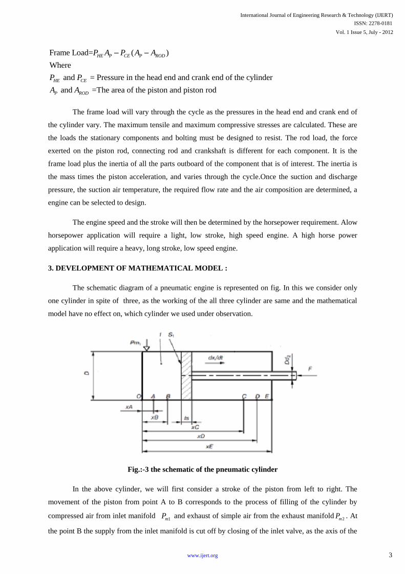
Frame Load= ( )
Where
and = Pressure in the head end and crank end of the cylinder
and =The area of the piston and piston rod
HE P CE P ROD
HE CE
P ROD
P A P A A
P P
A A
The frame load will vary through the cycle as the pressures in the head end and crank end of
the cylinder vary. The maximum tensile and maximum compressive stresses are calculated. These are
the loads the stationary components and bolting must be designed to resist. The rod load, the force
exerted on the piston rod, connecting rod and crankshaft is different for each component. It is the
frame load plus the inertia of all the parts outboard of the component that is of interest. The inertia is
the mass times the piston acceleration, and varies through the cycle.Once the suction and discharge
pressure, the suction air temperature, the required flow rate and the air composition are determined, a
engine can be selected to design.
The engine speed and the stroke will then be determined by the horsepower requirement. Alow
horsepower application will require a light, low stroke, high speed engine. A high horse power
application will require a heavy, long stroke, low speed engine.
3. DEVELOPMENT OF MATHEMATICAL MODEL :
The schematic diagram of a pneumatic engine is represented on fig. In this we consider only
one cylinder in spite of three, as the working of the all three cylinder are same and the mathematical
model have no effect on, which cylinder we used under observation.
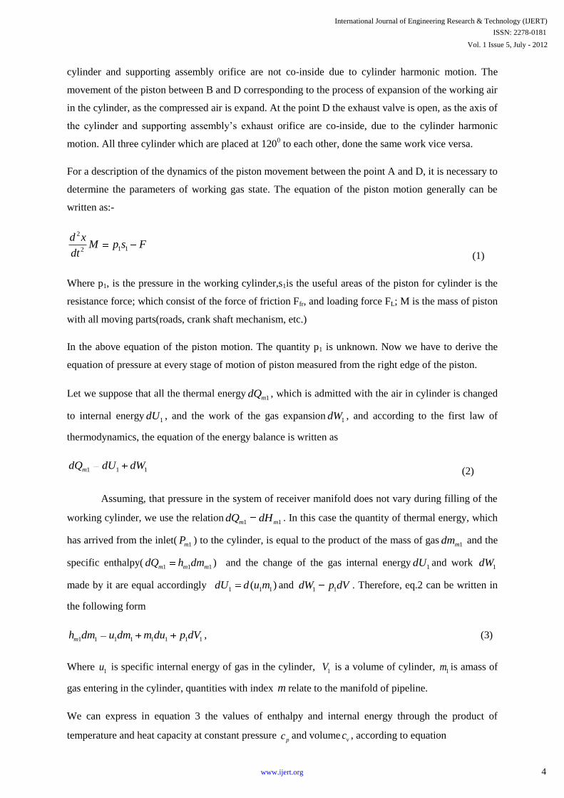
Fig.:-3 the schematic of the pneumatic cylinder
In the above cylinder, we will first consider a stroke of the piston from left to right. The
movement of the piston from point A to B corresponds to the process of filling of the cylinder by
compressed air from inlet manifold 1mP and exhaust of simple air from the exhaust manifold
2mP . At
the point B the supply from the inlet manifold is cut off by closing of the inlet valve, as the axis of the
International Journal of Engineering Research & Technology (IJERT)
Vol. 1 Issue 5, July - 2012
ISSN: 2278-0181
3www.ijert.org
Page 4
cylinder and supporting assembly orifice are not co-inside due to cylinder harmonic motion. The
movement of the piston between B and D corresponding to the process of expansion of the working air
in the cylinder, as the compressed air is expand. At the point D the exhaust valve is open, as the axis of
the cylinder and supporting assembly’s exhaust orifice are co-inside, due to the cylinder harmonic
motion. All three cylinder which are placed at 1200 to each other, done the same work vice versa.
For a description of the dynamics of the piston movement between the point A and D, it is necessary to
determine the parameters of working gas state. The equation of the piston motion generally can be
written as:-
2
1 12
d xM p s F
dt (1)
Where p1, is the pressure in the working cylinder,s1is the useful areas of the piston for cylinder is the
resistance force; which consist of the force of friction Ffr, and loading force FL; M is the mass of piston
with all moving parts(roads, crank shaft mechanism, etc.)
In the above equation of the piston motion. The quantity p1 is unknown. Now we have to derive the
equation of pressure at every stage of motion of piston measured from the right edge of the piston.
Let we suppose that all the thermal energy1mdQ , which is admitted with the air in cylinder is changed
to internal energy1dU , and the work of the gas expansion
1dW , and according to the first law of
thermodynamics, the equation of the energy balance is written as
1 1 1mdQ dU dW (2)
Assuming, that pressure in the system of receiver manifold does not vary during filling of the
working cylinder, we use the relation1 1m mdQ dH . In this case the quantity of thermal energy, which
has arrived from the inlet(1mP ) to the cylinder, is equal to the product of the mass of gas
1mdm and the
specific enthalpy(1 1 1m m mdQ h dm ) and the change of the gas internal energy
1dU and work 1dW
made by it are equal accordingly 1 1 1( )dU d u m and
1 1dW p dV . Therefore, eq.2 can be written in
the following form
1 1 1 1 1 1 1 1mh dm u dm m du p dV , (3)
Where 1u is specific internal energy of gas in the cylinder,
1V is a volume of cylinder, 1m is amass of
gas entering in the cylinder, quantities with index m relate to the manifold of pipeline.
We can express in equation 3 the values of enthalpy and internal energy through the product of
temperature and heat capacity at constant pressure pc and volume
vc , according to equation
International Journal of Engineering Research & Technology (IJERT)
Vol. 1 Issue 5, July - 2012
ISSN: 2278-0181
4www.ijert.org
Page 5
1 1 1 1 1 1 1 1p m v vc T dm c T dm c m du p dV (4)
The equation of state of the real gas in the working cavity is written as
1 1 1 1pV zm RT (5)
Where R is the gas constant and compressibility factor z determines the extent of non-ideality of the
working fluid. Numerical calculation of the compressibility factor z for air or nitrogen, accomplished
in the approach proposed in ref.[7] for the real gases, showed that in the pressure range considered
(P=0.1…..3.5MPa) and temperature range T ≥210k the assumption that z = 1 is highly accurate, and
the gas can be treated as ideal.
Substituting in equation 4 the value1 1m dT ,taken from equation 5 with the approximation z=1, and
using the common notationp
v
ck
cand
p vc c R where k is the adiabatic exponent, after simple
transformations one can obtain the following expression
1 1 1 1 1 1mkRT dm V dp kp dV (6)
We can then replace the mass of air1mdm , entering the volume
1V during time dt in equation 6, by the
corresponding value of the consumption function G1 (define as1 1mdm G dt ) and then express the
equation relative to pressure
1 1 11 1
1 1
mkG RT dt dVdp kp
V V (7)
We can also determine the function G1 that describes the gas consumption. For this purpose we can
find the parameters from Bernoulli’s equation. According to Bernoulli’s equation;
0dh vdv
For isentropic flow this can be written as
1
1
0dp
vdv (1a)
If the flow is incompressible than constant
Then equation (1a) on integration fields
2
1
1
1 1constant
2dp dv
International Journal of Engineering Research & Technology (IJERT)
Vol. 1 Issue 5, July - 2012
ISSN: 2278-0181
5www.ijert.org
Page 6
21
1
1constant
2
pv (2a)
As we know when the flow is isentropically decelerated to zero velocity, the resultant pressure is the
stagnation pressure. Therefore, when v=0,
1 1mp p ,
1 1m,
Thus, constant in equation (2a) , 1
1
constantm
m
p
Therefore, 2 11
1 1
1
2
m
m
ppv ,
In incompressible flow since,
1 1 constantm ,
2
1 1 1
1
2mp v p ,
But for adiabatic,
0 0 01
p
kh c T RT
k, (3a)
10
1
m
m
pRT , 1
0
11
m
m
pkh
k, 2
0
1
2h v h ,
1p
kh c T RT
k, 2kRT And 1
1
pRT ,
2
1
11 1
pkh
k k, (4a)
From equation (4a) & (3a),
221
constant1 2
vk
, (5a)
At 0T , 0h , maxv v , From equation (3a),
2
0 max
1
2h v , (6a)
At00,v , From equation (5a),
2
00constant
1h
k, (7a)
By equation (5a),(6a)and (7a),
222 2 0
max 0
1 1
1 2 2 1v v h
k k,
Therefore,
2 111
1 1
1
1 2 1
m
m
ppk kv
k k, (8a)
International Journal of Engineering Research & Technology (IJERT)
Vol. 1 Issue 5, July - 2012
ISSN: 2278-0181
6www.ijert.org
Page 7
Then from (8a) we have,
21constant
1 2
k pv
k,
Of the adiabatic braked stream(parameters of braking).in this case we will put the velocity of a stream
equal to zero over the area of inlet valve into Bernoulli’s, then we have
2 111
1 1
1
1 2 1
m
m
ppk kv
k k (8)
Now one can find the velocity of air entering the first cylinder from Eq. 8
1 11
1 1
2( )
1
m
m
p pkv
k (9)
From the adiabatic equation
1
1 1
1 1
( ) k
m m
p
p (10)
One can find the value of air density ρ1 in the working cylinder,
1
11 1
1
( )km
m
p
p ,
By substituting expression (10) into formula (9) we have,
1
11 1
1
2[1 ( ) ]
1
k
km
m
pkv RT
k p, (11)
The gas consumption function can be defined as1 1 1 1 1G v , where a1 is the area of the cross section
of the inlet valve;1 is a coefficient of gas consumption through the inlet valve. Let us substitute the
velocity of gas, determined by formula 11, into the expression for the gas consumption. Then we
obtain
1
11 1 1 1 1
1
2[1 ( ) ]
1
k
km
m
pkG RT
k p (12)
If we substitute the gas density in the cylinder from equation (10) to (12) we can derive
1 1
1 11 1 1 1 1
1 1
2( ) [1 ( ) ]
1
k
k km m
m m
p pkG RT
p k p=
2 1
2 1 11 1 1 1 1
1 1
2[( ) ( ) ]
1
k
k km m
m m
p pkG RT
k p p=
2 1
1 11 1 1 1
1 1 1
2 1[( ) ( ) ]
1
k
k km
m m m
p pkG p
k RT p p
As a result, the function G1 of the gas consumption from the unlimited volume (manifold) can be
determined by the formula [8–11]
International Journal of Engineering Research & Technology (IJERT)
Vol. 1 Issue 5, July - 2012
ISSN: 2278-0181
7www.ijert.org
Page 8
2 1
1 11 1 1 1
1 1 1
2 1[( ) ( ) ]
1
k
k km
m m m
p pkG p
k RT p p (13)
Where pm1 and Tm1 are the gas pressure and temperature in manifold pm1..
Note that the losses of gas pressure in the pipeline and local resistances are taken into account by
introducing the coefficient of consumption µ [9, 11], which besides takes into account the compression
of flow stream during exhaust, the speed of the gas as it approach the aperture and other factors. More
often, this coefficient of consumption is determined experimentally or with the help of approximations.
When the flow of gas occurs within a short span of a pipe at high velocity, the exhaust process is
considered to be adiabatic, and it is possible to use formula 13. The process of compression of the gas
in a working cavity is described by Eq. 6, which we can solve simultaneously with Eq. 13. As a result
it is possible to determine the pressure p1 in cylinder as a function of time. We must note that this
process cannot be described by means of elementary polytropic process with a constant parameter, n.
In reality, it follows from formula 13, that the consumption G1 is a function of the pressure ratio, in
which the numerator is the pressure of the medium into which gas flows, and the denominator is the
pressure of the medium from which this gas moves.
We will present formula 13 for gas flow from a pipe in a more convenient form [9]
1 1 1 11
1
m
m
kpG
RT (14)
Where,2 1
( ) ( )k
k k ; 11
1m
p
p;
2
1
kK
k
In order to find the maximum of the gas consumption factor ,let us set its derivative to zero,
which one can be written as
2 1
12 1
0k kk
k k,
From which one can obtain the critical ratio of pressures
* 12
[ ]1
k
k
k (15)
It is necessary to distinguish between two regimes of the flow; subcritical, when the consumption
function G1 is determined by the formula 13, and supercritical, at which the maximum critical
consumption of gas G* is obtained after substitution of the critical ratio of pressures from Equation 15
into Equation 14[9]
* *
1 1 1
1
2
( 1)m
m
kG p
k RT (16)
Where * 0.5282 and for k=1.4
If we substitute the value of the critical gas consumption G* into Equation 7 instead of G1, we can
obtain the equation that describes the process during the supercritical mode in a cavity of changing
International Journal of Engineering Research & Technology (IJERT)
Vol. 1 Issue 5, July - 2012
ISSN: 2278-0181
8www.ijert.org
Page 9
volume
*
1 11 1
1 1
mkG RT dVdp dt kp
V V (17)
The analysis of Equation. 7, 13, 16 and 17 shows, that the process of change of gas state in a cylinder
being filled, both for variable and for constant volume does not coincide with any one of the
elementary thermodynamic processes, which occur with a constant polytropic exponent. The process
can be described using the variable polytropic exponent n, which, in the beginning of the process,
equals the adiabatic exponent, and then monotonically decreases,
0 ( 1)1 [ ]
kn (18)
Where, 00
1m
p
p; At σ = 1, i. e. at the end of process, the value of polytropic exponent asymptotically
approaches the isothermal exponent n =1.
Change of the gas state by polytropic process (with a constant polytropic exponent) is possible in
a working cylinder when there is a constant mass of gas. Some examples include the internal
combustion engines after closure of the inlet valve, in flap-valve pneumatic motors, where the
chamber is completely isolated by plates from the inlet and outlet ports, and in compression-driven
devices and accumulators, when there is expansion of the compressed gas. In the case of variable gas
quantity in a cylinder, it is necessary to investigate the process by the energy balance stated in equ (6).
Thus, we can obtain the differential equation for determination of the gas pressure during the
filling of cavity 1 in a general form, by substituting the value of gas consumption G1 from expression
14 into Equation (7)
1 1 1 1 11 1 1
1 1
mkp RTdp kp dV
dt V V dt (19)
Let’s consider the expansion stage of the pneumatic cylinder operation; the process of gas expansion
during the movement of piston from point B to point D. We will describe this polytropic process with
a parameter 1 ≤ n ≤1.4 , that allows us to take into account, to a first approximation, the possible
process of heat exchange in the pneumatic cylinder.
Then the pressure in the cylinder can be determined by the following expression,
1 1 ( )n
B
xB tsp p
x ts (20)
Where xB is the corresponding distance traveled by the piston to arrive at position B (see Fig. 1); x is
the current piston position; ts is a thickness of the piston; p1B is the gas pressure at the beginning of the
expansion stage.
As a result it is necessary to solve the next equation for determining the dynamic characteristics of the
piston motion in the pneumatic cylinder
International Journal of Engineering Research & Technology (IJERT)
Vol. 1 Issue 5, July - 2012
ISSN: 2278-0181
9www.ijert.org
Page 10
2
1 1 2 2
2
0,
,
0,
x xA
p s p s Fd xxA x xD
dt M
x xD
(21)
Thus the total set of the equation, describing the dynamics of the pneumatic cylinder can be presented
as
1 1 1 1 11 1 1
1 1
1 1
;
( ) if ;
m
n
B
kp RTdp kp dV
dt V V dt
if x xB
xB tsp p x xB
x ts
2
1 1 2 2
2
0,
,
0,
x xA
p s p s Fd xxA x xD
dt M
x xD
For the numerical solution of the derived differential parameters, describe the physical sizes and
operating conditions of the pneumatic cylinder.
4. MODELING OF THE OPERATION :
A computer program in MATLAB-SIMULINK and modeling in AUTOMOTIVE
STUDIO(PNEUMATIC SIMULATION) has been developed for calculation of the dynamic parameters of
the pneumatic cylinder by using the derived equations.
The following parameters and initial conditions were chosen for the simulation.
working fluid-air/nitrogen, R=298.8 J/kg-k ; adiabatic k=1.4 ; polytropic n=1.25exponents; initial pressure
in the cylinder=.942bar ; pressure in the manifold=7bar ; gas temperature in the manifold=300k ;
loading force=2N ; coefficient of friction=.15 ; gas consumption coefficient in cylinder=.7 ; diameter of
input and output valve=6mm ; diameter of the piston=23mm ; -initial piston speed=0 ; -mass of
piston=300gm ; piston stroke=50mm ; distance xA=2mm,xB=4mm,xC=47mm,xD=48mm ;
International Journal of Engineering Research & Technology (IJERT)
Vol. 1 Issue 5, July - 2012
ISSN: 2278-0181
10www.ijert.org
Page 11
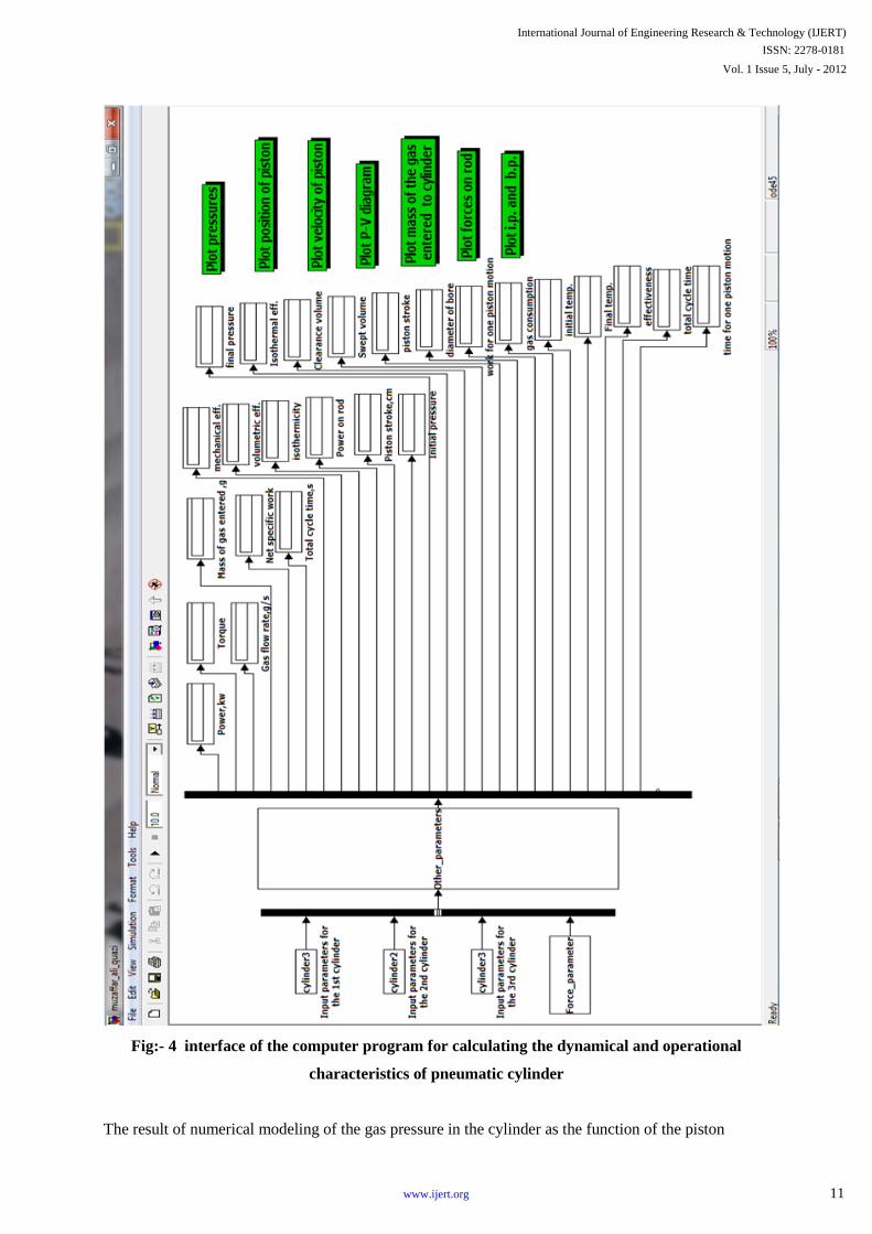
Fig:- 4 interface of the computer program for calculating the dynamical and operational
characteristics of pneumatic cylinder
The result of numerical modeling of the gas pressure in the cylinder as the function of the piston
International Journal of Engineering Research & Technology (IJERT)
Vol. 1 Issue 5, July - 2012
ISSN: 2278-0181
11www.ijert.org
Page 12
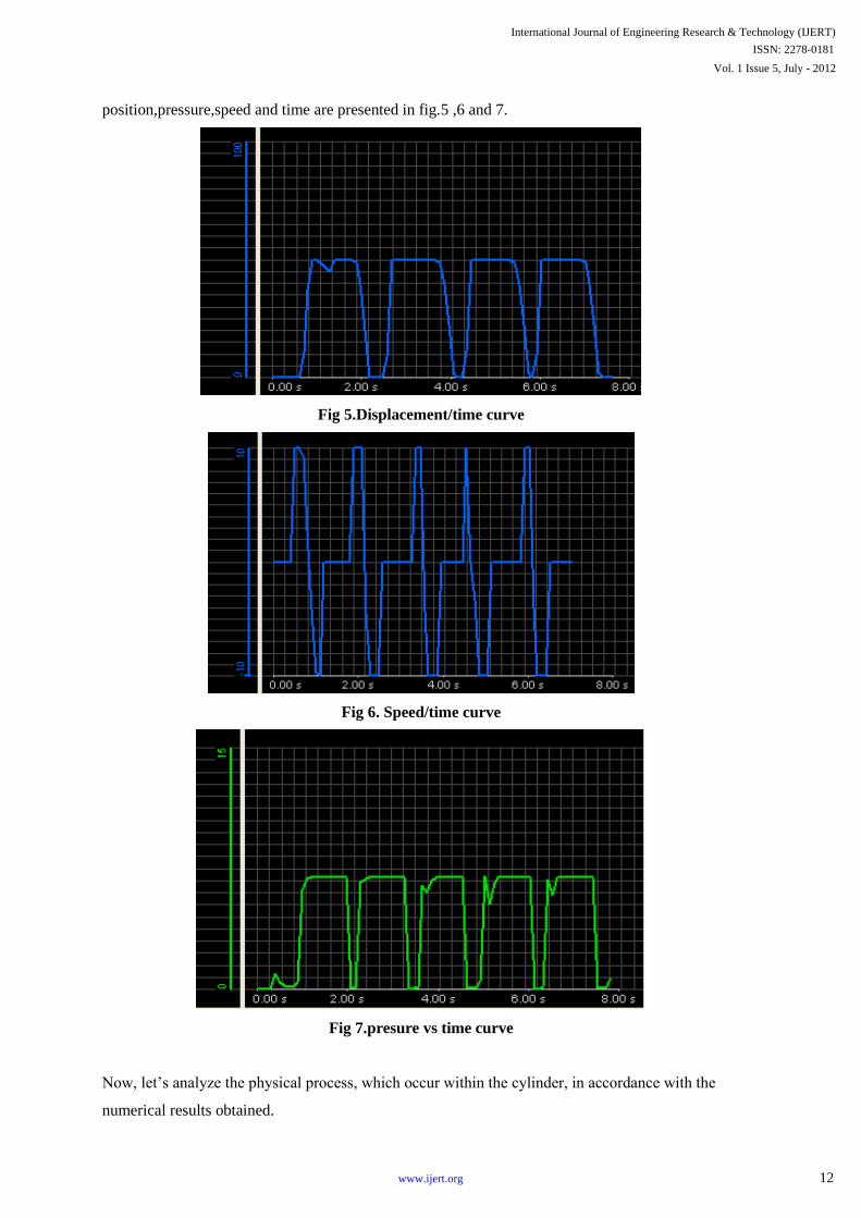
position,pressure,speed and time are presented in fig.5 ,6 and 7.
Fig 5.Displacement/time curve
Fig 6. Speed/time curve
Fig 7.presure vs time curve
Now, let’s analyze the physical process, which occur within the cylinder, in accordance with the
numerical results obtained.
International Journal of Engineering Research & Technology (IJERT)
Vol. 1 Issue 5, July - 2012
ISSN: 2278-0181
12www.ijert.org
Page 13
Until the force arising from the pressure in cylinder exceeds the force of friction and force of
useful resistance. During this period there is filling of the constant volume of cylinder, and the piston
remain motionless at point A.On the graph of pressure as a function of the piston motion this process
is displayed by a practically vertical segment near the value of x=2mm.
The following stage of the pneumatic cylinder operation is the continuing process of filling of
cylinder, for an already moving piston from point A up to B, the pressure in cylinder, which was
establish after filling the cylinder while the piston was motionless, falls to 6bar.
After the piston passes point B, the outlet valve of exhaust is open, the inlet valve of the working
cylinder is closed, and the piston continues to move to the right under the action of pressure force in
cylinder, during this period pressure in cylinder decreases.Further movement of the piston there
corresponds to the gas expansion with the closet inlet valve and open outlet valve. The final pressure
in the cylinder (.924bar) accurately coincides with the pressure in the exhaust pipeline.
Note that the mathematical model developed here allows us to calculate the time dependence
of the piston and velocity of the piston for pneumatic cylinder. The PV diagram is presented for the
process under consideration, using the pressure dependences obtained for piston motion in the
cylinder.
5. METHODOLOGY :
Data for each piston was entered into MATLAB Simulink computer simulation and
AUTOMOTIVE STUDIO software, of pneumatic engine operation to generate flow velocities .These
inputs include: the mass of the piston and all moving parts (piston, rod, rack, gear, etc.), useful areas of
each piston, input and output pressures, gas temperature at inlet, and required piston velocity. The
general equation of the piston motion can be written as follows:
2
1 1 2 22
d xM p s p s F
dt
The MFR required for cylinder can be calculated with the following equation .
.
M VA
Power produced by the engine:-
Power = 1
11 2 1
2
( )1
n
ni
pnN Q p V
n p
Work per cycle = 1
12 1
2
[( ) 1]1
n
ni
pnp V
n p
1
1 [( ) 1]c nvol p
s
Vr
V
6. RESULTS:
The main results obtained for the three cylinder pneumatic engine are as given below:-
Power(b.p.):-0.683hp
International Journal of Engineering Research & Technology (IJERT)
Vol. 1 Issue 5, July - 2012
ISSN: 2278-0181
13www.ijert.org
Page 14
Power(I.p.):-0.853hp
Volumetric efficiency(ηvol ):-0.72
Isothermal efficiency(ηiso ):-0.89
What is cost per CFM(ft3per minute)?
A Good Approximation
Typical Compressor produces 4 CFM per 1 Hp
1 Hp = 0.746/0.9 = 0.829kW
Therefore, 1 CFM = 0.207kW
4rs/kw-hr, 1 cfm = .828rs/hr
It takes 0.69rs/km.
7. CONCLUSION:
The three cylinder engine is fabricated, and mathematical model developed in this paper
allows one to accomplish the numerical simulation of the working process and to determine the main
dynamic characteristics of the pneumatic cylinder. By using the results of the numerical calculations,
the analysis of the particulars of changes of gas pressure in cylinder can be accomplished. The
subsequent stages of pneumatic cylinder operation can also be studied to calculate the main
operational characteristics.
NOMENCLATURE:
Asp specific useful work, kJ/kg;
a1, a2 Cross sections of inlet and outlet valves, m2;
B Coeffient of friction;
Cv Heat capacity at constant volume J / Kg. K ;
Cp Heat capacity at constant pressure J / Kg. K;
D Diameter of piston, m;
Dd1,Dd2 Rod diameters in cylinder, m;
d1, d2 Diameters of input and output valves, m;
F,FL,FFR Resistance, loading and friction forces, N;
Gas consumption factor;
G1, G 2 Gas consumption functions for cylinder, kg/s;
GN2 Specific gas consumption Kg / Kw-hr
Hm1 Enthalpy of gas entering the cylinder, J;
hm1 Specific enthalpy, J/kg;
K Adiabatic exponent;
M Mass of piston, kg;
International Journal of Engineering Research & Technology (IJERT)
Vol. 1 Issue 5, July - 2012
ISSN: 2278-0181
14www.ijert.org
Page 15
1 2,
Coefficients for gas consumption in cylinder;
m1
Mass of gas entering the cylinder, kg;
N Working power of cylinder, kW; n — polytropic exponent;
F Frequency of operation, rot/min; p1, p 2 — pressures in cylinder, MPa;
pm1, pm2 Pressures in 1st and 2nd manifolds, MPa;
p10, p20 Initial pressures in cylinder, MPa;
R Gas constant J / Kg.K
Qm1 Thermal energy entering the cylinder, J;
Qm2 Thermal energy, which is removed from cylinder, J;
ρ1, ρ2 Gas densities in cylinder, kg/m3;
ρm1, ρm2 Gas densities in 1st and 2nd pipelines, kg/m3;
S1, S2 Useful areas of piston for cylinder, m2;
σ0, σ1, σ2, σ* Ratios of pressures;
Tm1, Tm2 Gas temperatures in 1st and 2nd manifolds, K;
T1, T2 Gas temperatures in cylinder, K;
U1, U2 Internal energies of gas in cylinder, J;
u1 Specific internal energy of gas in the cylinder, J/kg;
V1, V2 Volumes of cylinder, m3;
υ1 Velocity of air entering the 1st cylinder ,m/s;
υm2 Velocity of air exhaust from thecylinder, m/s;
W1, W2 Works for gas expansion in cylinder, J;
X Current piston position, m;
xA,xB,xC,xD Distances (see Fig. 1), m; xE — piston stroke, m;
Z Compressibility factor
References
[1] ―Cryogenic engineering book‖, second Edison by Thomas m.flym,cryocee, inc., Louisville ,
Colorado.USA
[2] ―Air Engine Design for Machining Class‖, Hugh Currin,April 11, 2007.
[3] Sasa Trajkovic ―The Pneumatic Hybrid Vehicle, A New Concept for Fuel Consumption
Reduction‖, Doctoral thesis, Division of Combustion Engines, Department of Energy Sciences,
Faculty of Engineering, Lund university.
[4] Michael Beeman; ―Design and Evaluation of an Advanced Adiabatic Compressed Air Energy
Storage System at the Michigan-Utah Mine‖ ,A thesis submitted to the faculty of The University
of Utah in partial fulfillment of the requirements for the degree of Master of Science Department
of Mechanical Engineering, The University of Utah, August 2010
International Journal of Engineering Research & Technology (IJERT)
Vol. 1 Issue 5, July - 2012
ISSN: 2278-0181
15www.ijert.org
Page 16
[5] ―Gas dynamics‖ maurite j.zucrow,jo D Hoffman, school of mechanical engineering Purdue
university
[6] Compressor hand book,Paul C. Hanlon Editor,McGraw-Hill.
[7] ―Thermodynamics fundamentals for application‖ john p.o’connell, j.m.haile,university of
Virginia, Cambridge university.
[8] ―Fluid power with application‖,6th ed., by Anthony Esposito,professor emeritus, department
of manufacturing Engg.Miami University, oxford, Ohio.
[9] J.m.tressler, T.clement, H.kazerooni, M.lim, ―Dynamic behavior of pneumatic system for
lower extremity extenders‖, university of California at Berkeley,(2002 IEEE).
[10] Y.Y. Lin-Chen, J. Wang, Q.H. Wu Department of Electrical Engineering and Electronics, ―A
software tool development for pneumatic actuator system simulation and design‖, The
University of Liverpool, Brownlow Hill, Liverpool L69 3GJ, UK . 2003.
[11] Tony Wong, Pascal Bigras, Department of Automated Manufacturing Engineering, ―A
software application for visualizing and understanding hydraulic and pneumatic networks‖,
École de technologies supérieure University of Quebec, Daniel Cervera ,Department of
Mechanical Engineering Technologies, College de Valleyfield
[12] Simulink, Getting Started Guide,R2011b (Matlab&Simulink)
[13] Reciprocating Compressor Performance and Sizing Fundamentals, ―A Practical Guide to
Compressor Technology”, Second Edition, By Heinz P. Bloch Copyright © 2006 John Wiley
& Sons, Inc.
Author’s Affiliations
Muzaffar Ali Quazi
P.G.Scholar ,
School of Mechanical & Building Sciences
VIT University, Vellore-14,
Tamilnadu, India
*P.Baskar (Corresponding author)
Assistant Professor
School of Mechanical & Building Sciences
VIT University, Vellore-14,
Tamilnadu, India
International Journal of Engineering Research & Technology (IJERT)
Vol. 1 Issue 5, July - 2012
ISSN: 2278-0181
16www.ijert.org


![2011 - Karthikeyan Ponnusamy - ClinicalOutcomesWithRoboticSurgery[Retrieved-2014!05!25]](https://static.documents.pub/doc/80x56/577cc9891a28aba711a403cc/2011-karthikeyan-ponnusamy-clinicaloutcomeswithroboticsurgeryretrieved-20140525.jpg)


