AD-A79 987 MARYLAND UNIV COLLEGE PARK COMPUTER VISION LA8 F/S 9/3 PARALLEL OPERATIONS ON 3IARY IMAGES.(U) NOV 79 R KLETTE AFOSR-77-3271 UNCLASSIFIED TR-822 AFOSR-TR-80-0078 ML molnlIIIIIIiIII EIIIE IIIEEI
Transcript
AD-A79 987 MARYLAND UNIV COLLEGE PARK COMPUTER VISION LA8 F/S 9/3PARALLEL OPERATIONS ON 3IARY IMAGES.(U)NOV 79 R KLETTE AFOSR-77-3271
UNCLASSIFIED TR-822 AFOSR-TR-80-0078 ML
molnlIIIIIIiIIIEIIIE IIIEEI
UNWVERSiTY OF MARYLAND
COMPUTER SCIENCE CENTERCOLLEGE PARK, MARYLAND
7 ,I
80 1 29 012,
r o.~ 79
PARALL.EL WiRATIONS ON BINARY IM S.
~ io Renhard Kiettee
_r I - .l
tuer V3islon oratoryComputer Science Center JAN30 110University of MarylandCollege Park, MD 20742LSU U Lb
E" Approvedforpublicorelease;.
J distribution unlimited.
ABSTRACT ~ 'i4It is a well-known fact that parallel logical operations
and shifts are useful for speeding up certain computationaltasks in binary image processing. A theoretical model forcomputation is given using these operations as basic instruc-tions. Some examples demonstrate the utility of such a parallelprocessing system for fast solutions, e.g., the recognition ofrectangles, squares, and isosceles right triangles can be donewithin time O(logN) for input images of size NxN.
AIR FORCE OFFICE OF SCIENTIFIC RESARH (ASC)NOTICE OF ':" 7 T...
I t ... ... ITTA L TO DDCThis tC. v,,, rcvie1 and is
£ , v~n 2C L ; ,, ": .:.,: IA." 1 - i)J0-12 (7b).A. D. . uo32Technica Inf0-"- tion Officer
The support of the U.S. Air Force Office of Scientific Researchunder Grant AFOSR-77-3271 is gratefully acknowledged, as is thehelp of Kathryn Riley. The author also thanks Prof. AzrielRosenfeld for his careful reading of the manuscript.
In this paper, a binary image is a pattern of l's on a
background of O's, filling out a scanning field of a certain
size NxM. In the binary image
X = (X ij) i=0,l,...,N-l; j=0,...,M-l
X..=0 means that (i,j) is a background point, and X..=l that
(i,j) is an object point. It is well known (see, e.g., (1])
that many operations on binary images such as edge detection,
shrinking, expanding, or projection can be performed in parallel.
The following simple example of edge detection demonstrates this
computational approach:
Assume that all points (i,j) with Xi =1 represent a certain
object obtained as a result of thresholding a gray level image
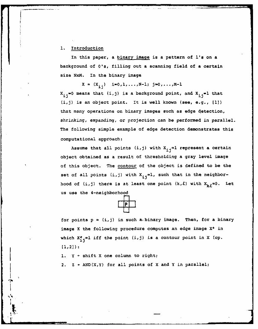
of this object. The contour of the object is defined to be the
set of all points (i,j) with X. =1, such that in the neighbor-1J
hood of (i,j) there is at least one point (k,t) with XkZ=O. Let
us use the 4-neighborhood
for points p - (i,j) in such a. binary image. Then, for a binary
image X the following procedure computes an edge image X* in
which X.=l iff the point (i,j) is a contour point in X (cp.El,2]):
1. Y - shift X one column to right;
2. Z - AND(X,Y) for all points of X and Y in parallel;
I'.
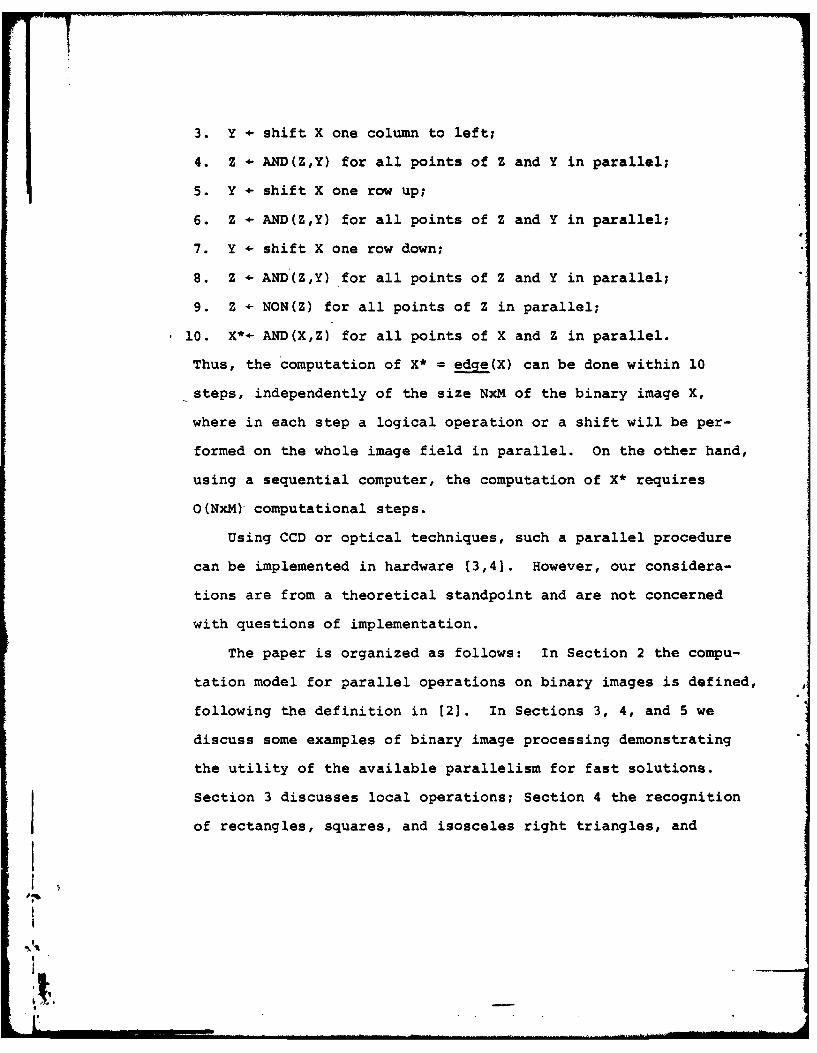
3. Y - shift X one column to left;
4. Z - AND(Z,Y) for all points of Z and Y in parallel;
5. Y - shift X one row up;
6. Z - AND(Z,Y) for all points of Z and Y in parallel;
7. Y - shift X one row down;
8. Z - AND(Z,Y) for all points of Z and Y in parallel;
9. Z - NON(Z) for all points of Z in parallel;
10. X*- AND(X,Z) for all points of X and Z in parallel.
Thus, the computation of X* = edge(X) can be done within 10
steps, independently of the size NxM of the binary image X,
where in each step a logical operation or a shift will be per-
formed on the whole image field in parallel. On the other hand,
using a sequential computer, the computation of X* requires
O(NxM) computational steps.
Using CCD or optical techniques, such a parallel procedure
can be implemented in hardware [3,4]. However, our considera-
tions are from a theoretical standpoint and are not concerned
with questions of implementation.
The paper is organized as follows: In Section 2 the compu-
tation model for parallel operations on binary images is defined,
following the definition in [2]. In Sections 3, 4, and 5 we
discuss some examples of binary image processing demonstrating
the utility of the available parallelism for fast solutions.
Section 3 discusses local operations; Section 4 the recognition
of rectangles, squares, and isosceles right triangles, and
1.
Section 5 the computation of area and perimeter for a simply
connected object [1].
lacslon For
Justiiatlar
DistributionL_
i Availabi.i _.CodesAvail id/or
Dst speclal
1~
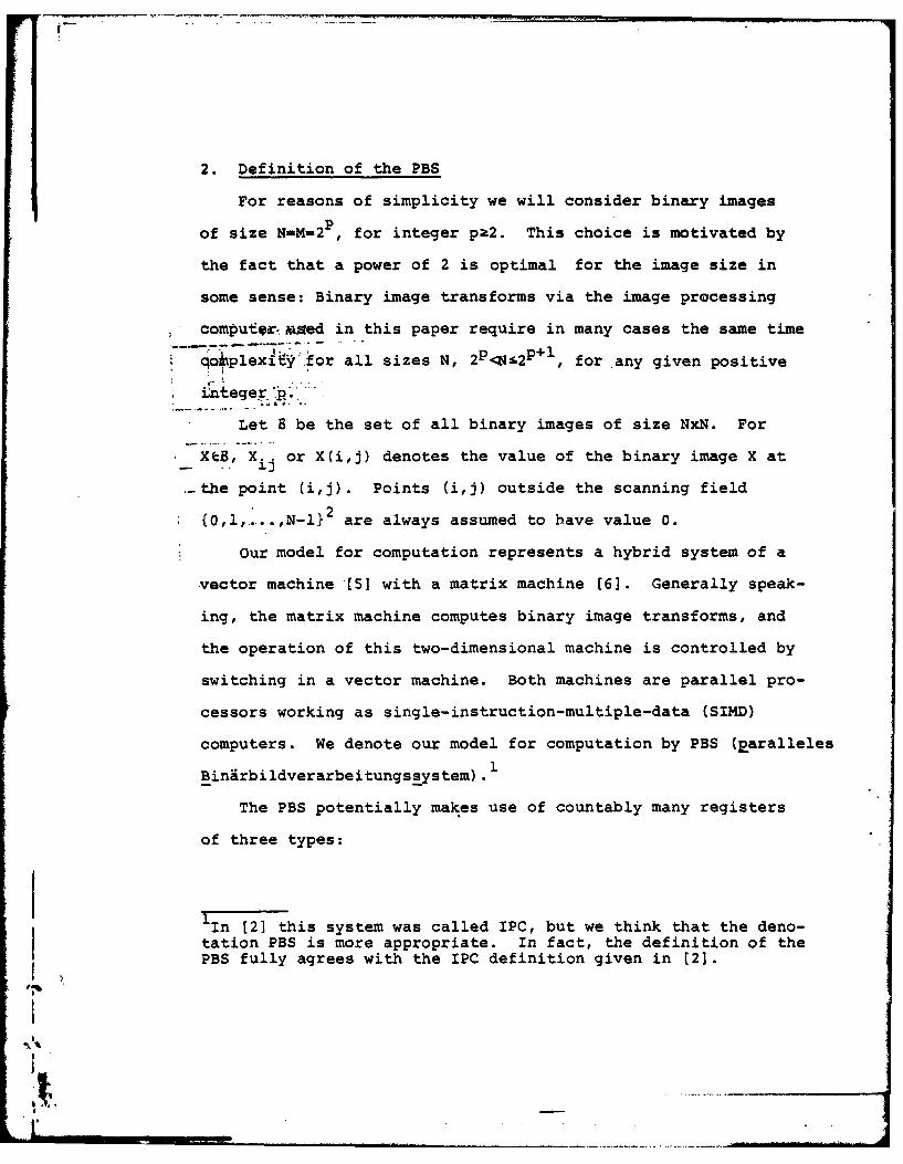
2. Definition of the PBS
For reasons of simplicity we will consider binary images
of size N=M-2P , for integer pk2. This choice is motivated by
the fact that a power of 2 is optimal for the image size in
some sense: Binary image transforms via the image processing
computormied in this paper require in many cases the same time
!qciplexftyi.for all sizes N, 2P<4N-2p + , for any given positive
iiegerp.
Let B be the set of all binary images of size NxN. For
* XeS, X. or X(i,j) denotes the value of the binary image X at
.-the point (i,j). Points (i,j) outside the scanning field
2{,l,.. ,N-l}2 are always assumed to have value 0.
Our model for computation represents a hybrid system of a
vector machine [5] with a matrix machine (6]. Generally speak-
ing, the matrix machine computes binary image transforms, and
the operation of this two-dimensional machine is controlled by
switching in a vector machine. Both machines are parallel pro-
cessors working as single-instruction-multiple-data (SIMD)
computers. We denote our model for computation by PBS (paralleles
Binirbildverarbeitungssystem).
The PBS potentially makes use of countably many registers
of three types:
1 In [2] this system was called IPC, but we think that the deno-tation PBS is more appropriate. In fact, the definition of thePBS fully agrees with the IPC definition given in (2].
1%
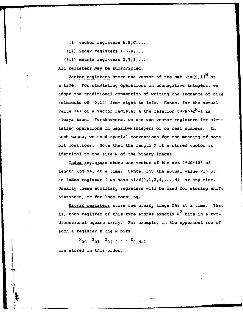
(i) vector registers A,B,C,...
(ii) index registers I,J,K,...
(iii) matrix registers XY,Z,...
All registers may be subscripted.
Vector registers store one vector of the set V:-{0,1}N at
a time. For simulating operations on nonnegative integers, we
adopt the traditional convention of writing the sequence of bits
(elements of {0,1}) from right to left. Hence, for the actual
value <A> of a vector register A the relation O <A>i 2N-I is
always true. Furthermore, we can use vector registers for simu-
lating operations on negative integers or on real numbers. In
such cases, we need special conventions for the meaning of some
bit positions. Note that the length N of a stored vector is
identical to the size N of the binary images.
Index registers store one vector of the set O*O* 0* of
length log N+1 at a time. Hence, for the actual value <I> of
an index register I we have <I>E{0,1,2,4,...,N}, at any time.
Usually these auxiliary registers will be used for storing shift
distances, or for loop count1ng.
Matrix registers store one binary image XEB at a time. That
is, each register of this type stores exactly N2 bits in a two-
dimensional square array. For example, in the uppermost row of
such a register X the N bits
X0 0 X0 1 X0 2 * * X 0,N. 1
are stored in this order.
I.
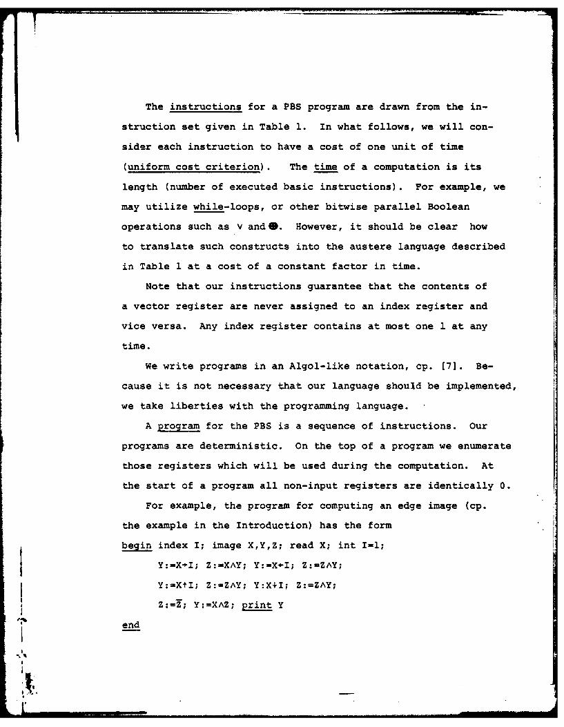
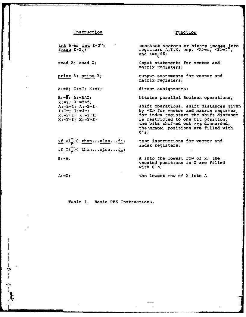
The instructions for a PBS program are drawn from the in-
struction set given in Table 1. In what follows, we will con-
sider each instruction to have a cost of one unit of time
(uniform cost criterion). The time of a computation is its
length (number of executed basic instructions). For example, we
may utilize while-loops, or other bitwise parallel Boolean
operations such as V and@. However, it should be clear how
to translate such constructs into the austere language described
in Table 1 at a cost of a constant factor in time.
Note that our instructions guarantee that the contents of
a vector register are never assigned to an index register and
vice versa. Any index register contains at most one 1 at any
time.
We write programs in an Algol-like notation, cp. [7]. Be-
cause it is not necessary that our language should be implemented,
we take liberties with the programming language.
A program for the PBS is a sequence of instructions. Our
programs are deterministic. On the top of a program we enumerate
those registers which will be used during the computation. At
the start of a program all non-input registers are identically 0.
For example, the program for computing an edge image (cp.
the example in the Introduction) has the form
begin index I; image X,Y,Z; read X; int I=1;
Y:=X-1I; Z:=XAY; Y:=X-I; Z:-ZAY;
Y:=XtI; Z:=ZAY; Y:X+I; Z:=ZAY;
Z:=Z; Y:=XAZ; print Y
end
Instruction Function
int A=m; int 1=2 n; constant vectors or binary images Antoage X- registers A,I,X, esp. <A)-m, <I>=2and X-X 0 B;
read A; read X; input statements for vector andmatrix registers;
print A; print X; output statements for vector and
matrix registers;
A:-B; I:=J; X:=Y; direct assignments;
A:=B; A:=BAC; bitwise parallel Boolean operations,X:Y=; X:=YAZ;AK:B-I; A:=BI; shift operations, shift distances givenI:J-; I:=J; by <I> for vector and matrix register,X:=YI; X:=Y-I; for index registers the shift distanceX:=YtI; X:=Y+I; is restricted to one bit position,
the bits shifted out are discarded,the vacated positions are filled withO's;
if A{}0 then...else.. .fi; test instructions for vector andindex registers;
if I( }0 then.. .else ...fi;
X:=A; A into the lowest row of X, thevacated positions in X are filledwith O's;
A:=X; the lowest row of X into A.
Table 1. Basic PBS Instructions.
St .
,.Mon
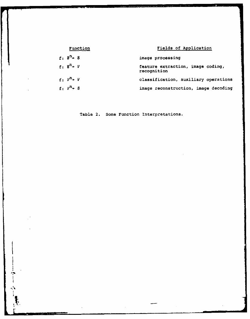
According to a given program the PBS computes a certain
function
f: V x an 2 Vm 1 x 8m 2.
Possible interpretations of such functions are listed in Table
2. Such a function belongs to the complexity class
PBS - TIME(T(N))
iff this function can be computed on PBS within time O(T(N)).
In this, the time complexity is taken as the maximum complexity
over all inputs (worst-case complexity). E.g., we have seen
that the function edge:B- B belongs to the complexity class
PBS-TIME(l).
According to Table 1, test instructions for matrix registers
(Is X identical to 0 in all bit positions, or not?) may be per-
formed by a PBS subroutine within time O(log N). To see this,
let
zero(X):=if X-0 then 1 else 0 fi.
The function zero:BV belongs to the complexity class
PBS-TIME(log N):
begin vector A; index I; image X,Z;
int I=N/2; read X;
while I0 do
Z:=X+I; X:=XVZ; 1:-I- od;
end if A=O then print 1 else print 0 fi;
I end
,,
Function Fields of Application
f: 8n. . image processing
f: 8n. V feature extraction, image coding,recognition
f: Vn. V classification, auxiliary operations
f: Vn. S image reconstruction, image decoding
Table 2. Some Function Interpretations.
II
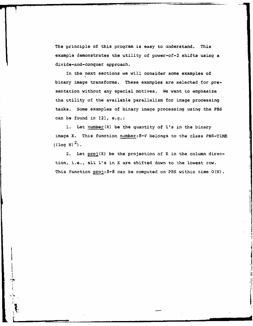
The principle of this program is easy to understand. This
example demonstrates the utility of power-of-2 shifts using a
divide-and-conquer approach.
In the next sections we will consider some examples of
binary image transforms. These examples are selected for pre-
sentation without any special motives. We want to emphasize
the utility of the available parallelism for image processing
tasks. Some examples of binary image processing using the PBS
can be found in [2], e.g.:
1. Let number(X) be the quantity of l's in the binary
image X. This function number:B-V belongs to the class PBS-TIME
((log N) 2
2. Let proj(X) be the projection of X in the column direc-
tion, i.e., all l's in X are shifted down to the lowest row.
This function proj:-8 can be computed on PBS within time O(N).
tI
'I'
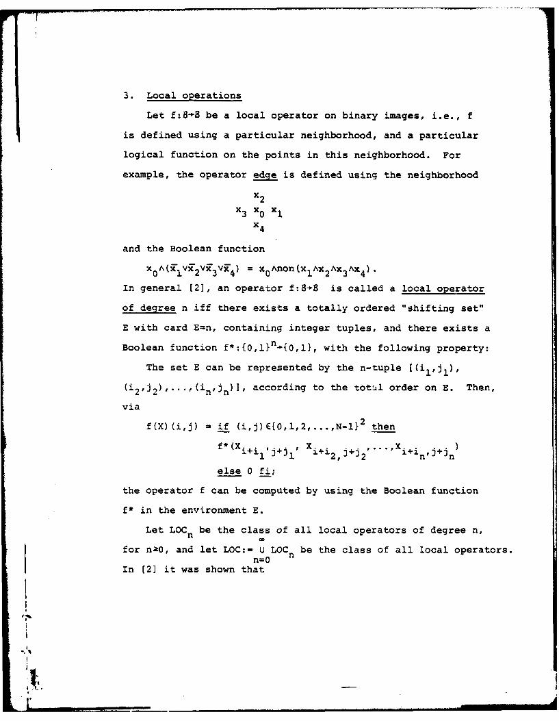
3. Local operations
Let f:8-8 be a local operator on binary images, i.e., f
is defined using a particular neighborhood, and a particular
logical function on the points in this neighborhood. For
example, the operator edge is defined using the neighborhood
x2x3 x0 x1
x4
and the Boolean function
x0A(XV12Vx3V'4 ) = x0Anon(x1 X2 X3 Ax4 ).
In general [2], an operator f:B-B is called a local operator
of degree n iff there exists a totally ordered "shifting set"
E with card E=n, containing integer tuples, and there exists a
Boolean function f*:{O,l}n_{O,l}, with the following property:
The set E can be represented by the n-tuple C(il,jl),
(i2j2)...(nJn)], according to the totul order on E. Then,
via
f(X)(i,j) = if (i,j)E{0,1,2,...,N-I}2 then
f* .. )(Xi+ilj+j, i+i2,j+j2' "'i+inj+jn
else 0 fi;
the operator f can be computed by using the Boolean function
f* in the environment E.
Let LOCn be the class of all local operators of degree n,
for nh0, and let LOC:= U LOC be the class of all local operators.n=O
In [2] it was shown that
1. if n<(2N-l) 2 LOCn C LOC n+I;
2. LOCn=LOC, for all na(2N-l)2 ; and
3. the cardinality of the class LOC is equal to
22 (N- )2. [N 2N_ (N 2 2N - N+l)+(N-_) 2
From property 3 we have ii. particular that there exist operators
f 2-8 which are not in LOC.
Let fELOC be an arbitrary operator with environment
[(ilJ I ) , (i2,J 2 ) , . . . , (in,Jn) Hand with Boolean function f*.
Then f can be computed on PBS according to the following general
program:
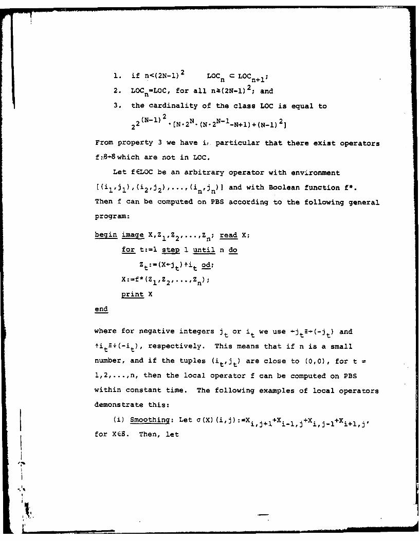
begin image X,ZI, Z2 ,... ,Zn; read X;
for t:=l step 1 until n do
Zt:=(X4-jt)tit od;
X:=f*(Zl,Z2,...,Z n);
print X
end
where for negative integers jt or it we use +jt-(-jt) and
tit-+(-it), respectively. This means that if n is a small
number, and if the tuples (it,it) are close to (0,0), for t =
1,2,...,n, then the local operator f can be computed on PBS
within constant time. The following examples of local operators
demonstrate this:
(i) Smoothing: Let a(X)(i,j):=X i,j+l+Xil,j+X i ,j-l+ij,
for XESB. Then, let
,,.
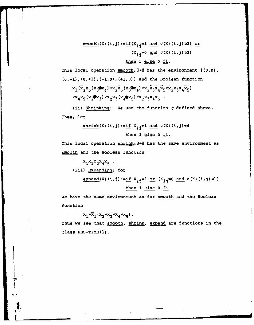
smooth(X)(i,j):=if(X..=l and a(X)(i,j)a2) or
(Xij =0 and a(X) (i,j) 3)
then 1 else 0 fi.
This local operation smooth:B-8 has the environment [(0,0),
(0,-l),(0,+l),(-i,0),(+i,0)] and the Boolean function
we perform four local operations on the input image X only
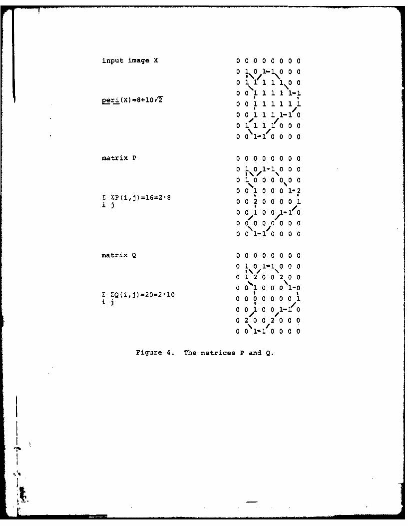
(cp. (10]) within constant time. Using the function number
and the addition on vector registers we get the values
EZEP(i,j) and IEZQ(i,j) within time O((log N)2). For multipli-
cation by /7 we use the convention that the first bit position
of a vector register (i.e., on the right end) indicates if the
number in this vector register is a multiple of /T or not. For
example
0 101010011 10
is the final output for the object S in Figure 4. Thus, we
have:
Proposition 5. The function peri(X)=a+b/I can be computed
on PBS within time O((log N) 2).
*1it
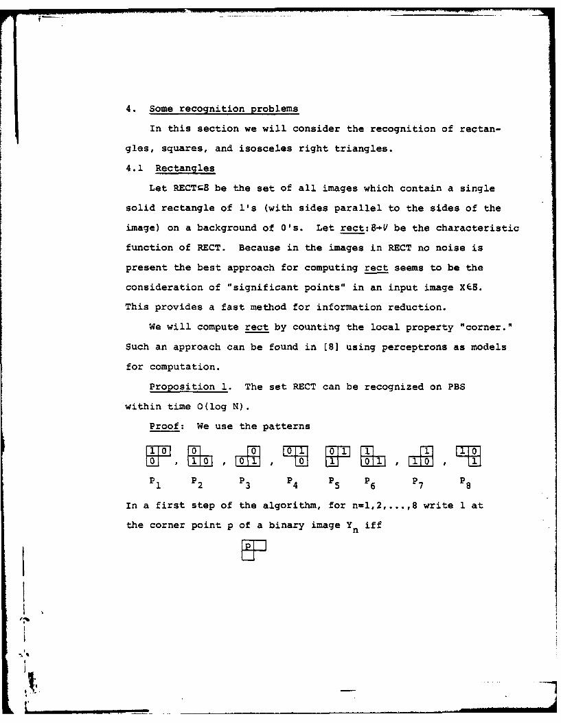
6. Conclusions
We have defined a model for parallel processing (PBS) which
formalizes Boolean operations and shifts on binary images
(Boolean matrices). It was shown that power-of-two shifts are
very useful for fast programs using a divide-and-conquer approach.
The matrix registers of the model used for computation represent
bit planes of a possible hardware implementation of this system.
Using several bit planes, grayscale pictures can be encoded in
this system. In this sense the algorithms demonstrated on binary
images (local operations, recognition of geometric objects, area,
perimeter) are only small examples of problems which can be
solved using the PBS.
'il
it,
References
(1] Rosenfeld, A., and A. Kak. Digital Picture Processing.Academic Press, New York, 1976.
(2] Klette, R. A Parallel Computer for Digital Image Processing.EIK 15 (1979), 237-263.
[3] Schaefer, D. H. and J. P. Strong. Tse Computers. GoddardSpace Flight Center Report X-943-75-14, January 1975.
[4) Milgram, D. L., A. Rosenfeld, T. Willett, and G. Tisdale.Algorithms and Hardware Technology for Image Recognition.Final Report to U.S. Army Night Vision Laboratory, FortBelvoir, March 31, 1978.
[51 Pratt, V. R. and L. J. Stockmeyer. A Characterization ofthe Power of Vector Machines. J. Computer Syst. Sci. 12(1976), 198-227.
(6] Klette, R. Fast Matrix Multiplication by Boolean RAM inLinear Storage. Lecture Notes in Computer Science 64 (1978),308-314.
[71 Aho, A.V., J. E. Hopcroft, and J. D. Ullman. The Design andAnalysis of Computer Algorithms. Addison Wesley, Reading,Mass., 1974.
18] Minsky, M and S. Papert. Perceptrons. MIT Press, Cambridge,Mass., 1969.
[9] Dyer, C. R. Augmented Cellular Automata for Image Analysis.Dissertation, University of Maryland, College Park, 1979.
[10] Sankar, P. V. and E. V. Krishnamurthy. On the Compactnessof Subsets of Digital Pictures. University of Maryland,Computer Science Center, TR-587, September 1977.
"il
t utC~t~)rr LMu-. --
SECURITY CLASSIFICATION OFL T •REPORT DOCUMENTATIO " 'BREAD INSTRUCTIONS
BEFORE COMPLETING FORM
f.4tRrPOR" NUMBER GOVT ACCESSION NO S. RECIPIENT'S CATALOG NUMBER
VOSR.-TR. 80-00784. TITLE (and Subtitle) S. TYPE OF REPORT & PERIOD COVERED
PARALLEL OPERATIONS ON BINARY IMAGES Interims. PERFORMVG ORG. REPORT NUMBER
TR-8227. AUTNOR(@) S. CONTRACT OR GRANT NUMBER(S)
Reinhard Klette AFOSR 77-3271'
9. PERFORMING ORGANIZATION NAME AND ADDRESS / 10. PROGRAM ELEMENT. PROJECT. TASK
University of Maryland, Computer Vision AREA & WORK UNIT NUMBERS
Laboratory, Computer Science CenterCollege Park, MD 20742 61102F 2304/A2
It. CONTROLLING OFFICE NAME AND ADDRESS 1Z. REPORT DATE
November 1979Air Force Office of Scientific Research/NM 13. NUMBER OF PAGESBolling AFB, Washington, DC 20332 32
14. MONITORING AGENCY NAME & ADDRESS(if different from Controllind Office) IS. SECURITY CLASS. (of tle report)
UNCLASSIFIEDIS. OECLASSIFICATIOR/OOWNGRAOING
SCHEDULE
IS. DISTRIBUTION STATEMENT (of this Report)
Approved for ppblic release; distribution unlimited.
17. DISTRIBUTION STATEMENT (of the abetract entered In Block 20, It different from Report)
IS. SUPPLEMENTARY NOTES
19. KEY WORDS (Continue on reverse side If neceeery and Identify by block number)
_" ABSTRACT (Continue on reveree side If neceeeery and Identify by block number)It is a well-known fact that parallel logical operations and shifts are use-
ful for speeding up certain compotational tasks in binary image processing. Atheoretical model for coupptation is given using these operations as basicinstructions. Some examples demonstrate the utility of such a parallel pro-
cessing system for fast solutions, e.g. the recognition of rectangles; squares,and isosceles right triangles can be done within time B(log N), for inputmages of size triangles can be done within time 0(log N), for input images ofsize NxN.
DD JAN ,13 147 UNCLASSIFIED- 1t SECURITY CLASSIFICATION OF THIS PAGE fiel Data Entored)