IEEE TRANSACTIONS ON PATTERN ANALYSIS AND MACHINE INTELLIGENCE, VOL. PAMI-7, NO. 2, MARCH 1985
Computing Geometric Properties of ImagesRepresented by Linear QuadtreesHANAN SAMET, MEMBER, IEEE, AND MARKKU TAMMINEN, MEMBER, IEEE
Abstract-The region quadtree is a hierarchical data structure thatfinds use in applications such as image processing, computer graphics,pattern recognition, robotics, and cartography. In order to save space,a number of pointerless quadtree representations (termed linear quad-trees) have been proposed. One representation maintains the nodes in alist ordered according to a preorder traversal of the quadtree. Usingsuch an image representation and a graph definition of a quadtree, ageneral algorithm to compute geometric image properties such as theperimeter, the Euler number, and the connected components of animage is developed and analyzed. The algorithm differs from the con-ventional approaches to images represented by quadtrees in that it doesnot make use of neighbor finding methods that require the location of anearest common ancestor. Instead, it makes use of a staircase-like datastructure to represent the blocks that have been already processed. Theworst-case execution time of the algorithm, when used to compute theperimeter, is proportional to the number of leaf nodes in the quadtree,which is optimal. For an image of size 2' X 2', the perimeter algorithmrequires only four arrays of 2n positions each for working storage. Thismakes it well suited to processing linear quadtrees residing in secondarystorage. Implementation experience has confirmed its superiority toexisting approaches to computing geometric properties for images repre-sented by quadtrees.
Index Terms-Computer graphics, connected component labeling,DF-expressions, Euler number, hierarchical data structures, image pro-cessing, linear quadtrees, pattern recognition, perimeter, quadtrees.
I. INTRODUCTIONT HE region quadtree [1 1] , [7] , a hierarchical data structure
based on a regular decomposition of space, has been thesubject of much research in recent years (see the survey in[22] ). It and its variants have been found to be useful in suchapplications as image processing, computer graphics, patternrecognition, robotics, and cartography. Many algorithms forstandard operations in these domains can be expressed as simpletree traversals where at each leaf a computation is performedinvolving that leaf and some or all of its bordering neighbors[18]. For images represented by quadtrees, algorithms for thecomputation of perimeter [17] and Euler number [4], as wellas connected component labeling [ 161, have been implementedin this way. The only difference between the tree traversals isin the type of the bordering neighbors that are examined.As an example of the quadtree, we briefly describe how it is
Manuscript received December 29, 1983. Recommended for accept-ance by S. Tanimoto. This work was supported in part by the NationalScience Foundation under Grant MCS-83-02118 and in part by the Fin-nish Academy.H. Samet is with the Department of Computer Science, University of
Maryland, College Park, MD 20742.M. Tamminen is with the Laboratory for Information Processing
Science, Helsinki University of Technology, Espoo, Finland.
o o o oo_ _00 0 01
0 001 1 I3
0o
0 0 11 000(a) Region (b) Binary array (c) Block decomposition of
the reeion in (a).Blocks in the regior areshaded.
37 38 39 40 57 58 59 60(d) Quadtree representation of the blocks in (c).
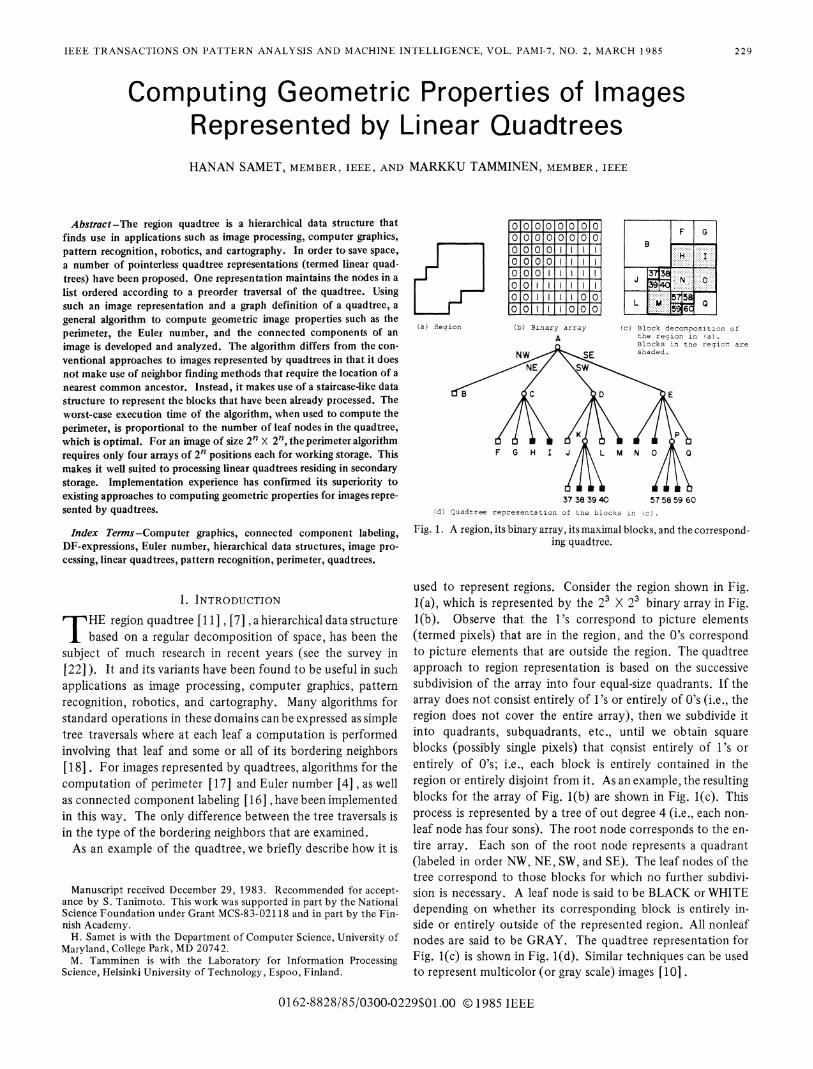
Fig. 1. A region, its binary array, its maximal blocks, and the correspond-ing quadtree.
used to represent regions. Consider the region shown in Fig.l(a), which is represented by the 23 X 23 binary array in Fig.l(b). Observe that the l's correspond to picture elements(termed pixels) that are in the region, and the 0's correspondto picture elements that are outside the region. The quadtreeapproach to region representation is based on the successivesubdivision of the array into four equal-size quadrants. If thearray does not consist entirely of l's or entirely of 0's (i.e., theregion does not cover the entire array), then we subdivide itinto quadrants, subquadrants, etc., until we obtain squareblocks (possibly single pixels) that cqnsist entirely of 1's orentirely of 0's; i.e., each block is entirely contained in theregion or entirely disjoint from it. As an example, the resultingblocks for the array of Fig. l(b) are shown in Fig. l(c). Thisprocess is represented by a tree of out degree 4 (i.e., each non-leaf node has four sons). The root node corresponds to the en-tire array. Each son of the root node represents a quadrant(labeled in order NW, NE, SW, and SE). The leaf nodes of thetree correspond to those blocks for which no further subdivi-sion is necessary. A leaf node is said to be BLACK or WHITEdepending on whether its corresponding block is entirely in-side or entirely outside of the represented region. All nonleafnodes are said to be GRAY. The quadtree representation forFig. l(c) is shown in Fig. l(d). Similar techniques can be usedto represent multicolor (or gray scale) images [10] .
IEEE TRANSACTIONS ON PATTERN ANALYSIS AND MACHINE INTELLIGENCE, VOL. PAMI-7, NO. 2, MARCH 1985
The quadtree was originally devised as an alternative to thebinary array image representation with the goal of saving spaceby grouping similar regions. However, more importantly, thehierarchical nature of the quadtree also results in savings inexecution time. In particular, algorithms for computing basicimage processing operations using a quadtree representationhave execution times that are only dependent on the numberof blocks in the image and not their size (e.g., for connectedcomponent labeling see [16]). Nevertheless, in actuality thespace required for pointers from a node to its sons is not trivialand processing pointer chains in external storage may be timeconsuming due to page faults. Consequently, there has been aconsiderable amount of interest in pointerless quadtree repre-sentations. They can be grouped into two categories. The firsttreats the image as an ordered collection of leaf nodes. Eachleaf is represented by a locational code corresponding to a se-quence of directional codes to locate the leaf along a path fromthe root of the tree. Locational codes have been used by anumber of researchers to represent quadtrees [12] , [27] , [5][ 14], [2] , [1], as well as in other related contexts [13], [3 ],[26]. The second represents the image in the form of a pre-order traversal of the nodes of its quadtree [9], [24].Pointerless quadtree representations such as those described
above are termed linear quadtrees.1 They are attractive be-cause of their relative compactness and their appropriatenessfor maintenance of the data in external storage. A linear quad-tree can be viewed as a sequential file that only supports theoperation NEXT( ) which yields, in sequence, the leaf nodes ofthe tree. Many image operations can be performed by scanningthe file, in its natural order, while keeping only one or twonodes in working storage. For example, the computation ofmoments and set operations (e.g., union, intersection, etc.) aredescribed in [9], [5] , and [14].In this paper, we show how linear quadtrees can be used in
conjunction with algorithms for operations that also requireinspection of neighbors of leaf nodes. However, we do nothave to use neighbor finding methods that are based on locatinga nearest common ancestor. Such methods are cumbersomefor linear quadtrees and are not explicitly used in [5], [1].Instead, to examine a particular neighboring node, its key iscalculated and the linear quadtree is searched (by a modifiedbinary search) to determine the BLACK leaf node with thegiven key. If such a leaf node is not found, then the color ofthe neighbor (WHITE or GRAY) is inferred from the nexthigher value in the tree (i.e., list). The key of the nearestcommon ancestor is implicitly determined in calculating theneighbor's key, but a search for the nearest common ancestoris not made. Nevertheless, the binary search is expensive. Wepresent a simple general algorithm for traversing linear quad-tree representations and computing geometric image propertiessuch as the perimeter, the Euler number, and the connectedcomponents. Our algorithm only assumes that the tree can be
1We use this term to denote any data structure based on a linear or-dering of the nodes of a quadtree. This is somewhat more general thanthe original definition of Gargantini [5], [6], who stores a list ofBLACK leaf nodes with their locatioral codes to represent the treestructure. The remaining nodes (WHITE and GRAY) can be inferredfrom a sorted list of the BLACK nodes.
traversed in preorder and does not require much internalstorage. For example, for an image of size 2' X 2', theperimeter algorithm requires only four arrays of 2' positionseach for working storage. We shall show that its worst-casetime complexity is O(N) where N is the number of leaf nodesin the quadtree.The rest of the paper is organized as follows. Section II con-
tains definitions and a description of the notation that we use.Section III presents a graph definition of a quadtree, which weuse to give abstract algorithms for the computation of perim-eter, connected component labeling, and Euler number. Sec-tion IV introduces our implementation with an algorithm forthe computation of perimeter using a linear quadtree represen-tation. Section V presents a more general algorithm for thecomputation of geometric properties using linear quadtrees.
II. DEFINITIONS AND NOTATIONEach node of a quadtree corresponds to a block in the original
image.2 Each block has four sides and four corners. At timeswe speak of sides and corners collectively as directions. Letthe four sides of a node's block be called its N, E, S, and Wsides. The four corners of a node's block are labeled NW, NE,SW, and SE, with the obvious meaning. Algorithms for thecomputation of geometric properties require the examinationof adjacent nodes. Such nodes are referred to as neighbors. Inorder to be more precise, given node P and a direction D, wesay that Q is the neighbor of P in direction D, i.e., neighbor(P, D) = Q when both of the following conditions are satisfied.
1) P and Q are adjacent along a side or a corner.2) If D is a diagonal direction (i.e., NW, NE, SW, or SE),
then node Q corresponds to the smallest block that shares theD corner of node P's block. Otherwise (D is one of the hori-zontal or vertical directions, i.e., N, E, S, or W), the blockcorresponding to Q is the smallest block (it may be GRAY) ofsize greater than or equal to the block corresponding to P.For example, in Fig. l(d) the E neighbor of node 38 is N;
the NE neighbor of node L is 39; and the N neighbor of nodeM is K. Nodes corresponding to blocks that are adjacent tothe border of the image have no neighbors in the direction ofthe border [e.g., the eastern sides of blocks G, I, 0, and Q inFig. 1(c)] . Note that this definition of neighbor differs slightlyfrom the one given in [18] . In particular, we permit diagonalneighbors to be of smaller size. Two other items are worthy ofnote. First, the neighbor function does not define a one-to-onecorrespondence (i.e., a node may be a neighbor in a given di-rection of several nodes, i.e., in Fig. 1, neighbor(J, N) = B,neighbor(37, N) = B, and neighbor(38, N) = B). Second, theneighbor function is not necessarily symmetric. For example,in Fig. 1, neighbor(37, N) = B, but neighbor(B, S) = D.For a quadtree corresponding to a 2n X 2n image array, we
say that the root is at level n. A node at level 0 corresponds toa single pixel in the image. Each pixel in the array has an xcoordinate and a y coordinate between 0 and 2n - 1, corre-sponding to its position in the array. The lower left-hand
2We use the terms block and node interchangeably. The term that isused depends on whether we are referring to a block decomposition[i.e., Fig. 1(c)] or a tree [Fig. 1(d)].
230
SAMET AND TAMMINEN: GEOMETRIC PROPERTIES OF LINEAR QUADTREE IMAGES
corner of the image is located at (0, 0), and the upper right-hand corner is located at (2' - 1, 2' - 1).In the presentation of our algorithms we use a linear quad-
tree representation that is based on a preorder tree traversal.Of course, our results are equally applicable to other linearquadtree representations. The traversal yields a string over thealphabet "(," "B," and "W," corresponding to GRAY, BLACK,and WHITE nodes, respectively. It is due to Kawaguchi andEndo [9] , and is called a DF-expression (denoting depth first).For example, the image of Fig. 1 has (W(WWBB(W(WBBBWB(BB(BBBWW as its DF-expression when the sons are visited inthe order NW, NE, SW, and SE. In order to facilitate the ex-pression of our algorithms, we will visit the sons in the orderSW, SE, NW, and NE. Using such an order, the DF-expressionfor the image of Fig. 1 is ((WBW(BBWB((BWBBWBBW(BBWW.It should be clear that the original image can be reconstructedfrom the DF-expression by observing that the degree of eachnonterminal (i.e., GRAY) node is always 4.
III. A GRAPH DEFINITION OF QUADTREES
As mentioned in Section I, algorithms for the computationof geometric properties of images represented by quadtrees are
implemented as tree traversals. At each node some or all ofthe adjacent nodes must be inspected, depending on the taskbeing performed. In this section, we give an alternative defini-tion of a quadtree in terms of a graph. Using such a definitionfacilitates the formulation of a number of geometric propertycomputation algorithms. In particular, it is especially wellsuited to linear quadtrees since it eliminates the need for theuse of neighbor finding techniques based on locating the nearestcommon ancestor [18] or searching [5], [1]. Instead, our
algorithms are expressed in terms of blocks, edges, and vertices.The partition of space induced by a quadtree may be viewed
as an undirected planar graph. The vertices of the graph corre-
spond to the corners of the leaf nodes comprising the quadtree.The edges of the graph are the sides of the leaf nodes. For ex-
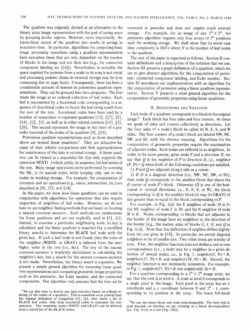
ample, Fig. 2 is the graph representation of the block decom-position in Fig. 1(c). The vertices are labeled AA-BF, and theedges are labeled xa-xy and ya-yy. More precisely, edges are
defined as follows: given a leafP and a side D between verticesVI and V2 of P, there exists an edge between V, and V2 ifand only if neighbor(P, D) is not GRAY (e.g., in Fig. 1, edgeye joins vertices AN and AR of 39, while there is no edge be-tween vertices Al and AR of J). In order to cope with leafnodes that are adjacent to the border (e.g., the W side of nodeL in Fig. 1), we say that the image is surrounded by WHITE or
BLACK as is appropriate to the task being performed.It is convenient to associate some additional information
with edges and vertices. First, we label edges and vertices as
BLACK, WHITE, or GRAY. An edge is defined to be GRAYif its adjacent leaf nodes differ in color, and it is BLACK(WHITE) if its adjacent leaf nodes are both BLACK (WHITE).Similarly, a vertex is said to be BLACK (WHITE) if all edgesemanating from it are BLACK (WHITE); otherwise, it is GRAY.For example, in Fig. 2 edge ys is BLACK, edge xf is WHITE,and edge ye is GRAY; vertex AT is BLACK, vertex Al isWHITE, and vertex AJ is GRAY. Second, the width of an
AA AB AC .ADxa xb xc
yi F yq G yv
ya B AE AFAG-: xd xe:. . ,, ...- ..-. ..... ...' ..--:. :-.i :.. --....
Yi H yr I yw.. ,: ..,. .: ,- ., ....-
AI AJ AK AAH -- ......AMxf xg xh -' xi xj A
yd 37 Yg 38- ykACyb J AN AkAP:xA N ys::ys 0 yx
ye 39 yh 4Q0: yIxm AR AVAQ ....AW
AS: AT. ::~:XP. x xrym 57 yO58- yt
'- AYyc L yf -M AX AZ Q YY
yn 59 YP60 yu yI,u XU ,: ,' ,,v '-'XW'.'..,.XX..y .BA BB BC BD BE BF
Fig. 2. Graph representation of the quadtree of Fig. 1.
edge is the distance between the two vertices comprising itand is accessed by the use of the function WID.The description of the relationship between blocks, edges,
and vertices is facilitated by the use of the TOUCH function.When X is a vertex, the value of TOUCH (X) is the set ofblocks whose corners meet at X. A similar definition holdsfor edges. For example, in Fig. 1, TOUCH(yj) = {B, H},TOUCH(AK) = {B, H, N, 38}, and TOUCH(AE) = {B, F, HI.The computation of the perimeter of an image represented
by a quadtree is a tree traversal where at each BLACK node welook for adjacent WHITE nodes [ 17]. Using our graph formu-lation of a quadtree, we merely need to accumulate the sum ofthe widths of all GRAY edges as shown by procedure PERIM-ETER given below.
integer procedure PERIMETER (Q);/* Compute the perimeter of quadtree Q. */begin
value quadtree Q;edge E;integer PER;PER -O;foreach E in {edges(Q)}do
beginif GRAY(E) then PER v PER + WID(E);
end;return (PER);
end;
Labeling the connected components of an image representedby a quadtree is a three-step process [16]. The first step is atree traversal where for each BLACK node we find all adjacentnodes and assign them the same label. If some of the nodeshave already been assigned a label, then we note the equivalence.The second step merges all the equivalence pairs that were gen-erated during the first step. The third step performs another
9 9
231
I2E2J TRANSACTLIONS ON PATTERN ANALYSIS AND MACHINE INTELLIGENCE, VOL. PAMI-7, NO. 2, MARCH 1985
.- ...
....- ....
......,.. .....
.,...,.- -..........
.. . -.... -.. .
. .... .i.
',... ;'.'. '.'..'.''.'..
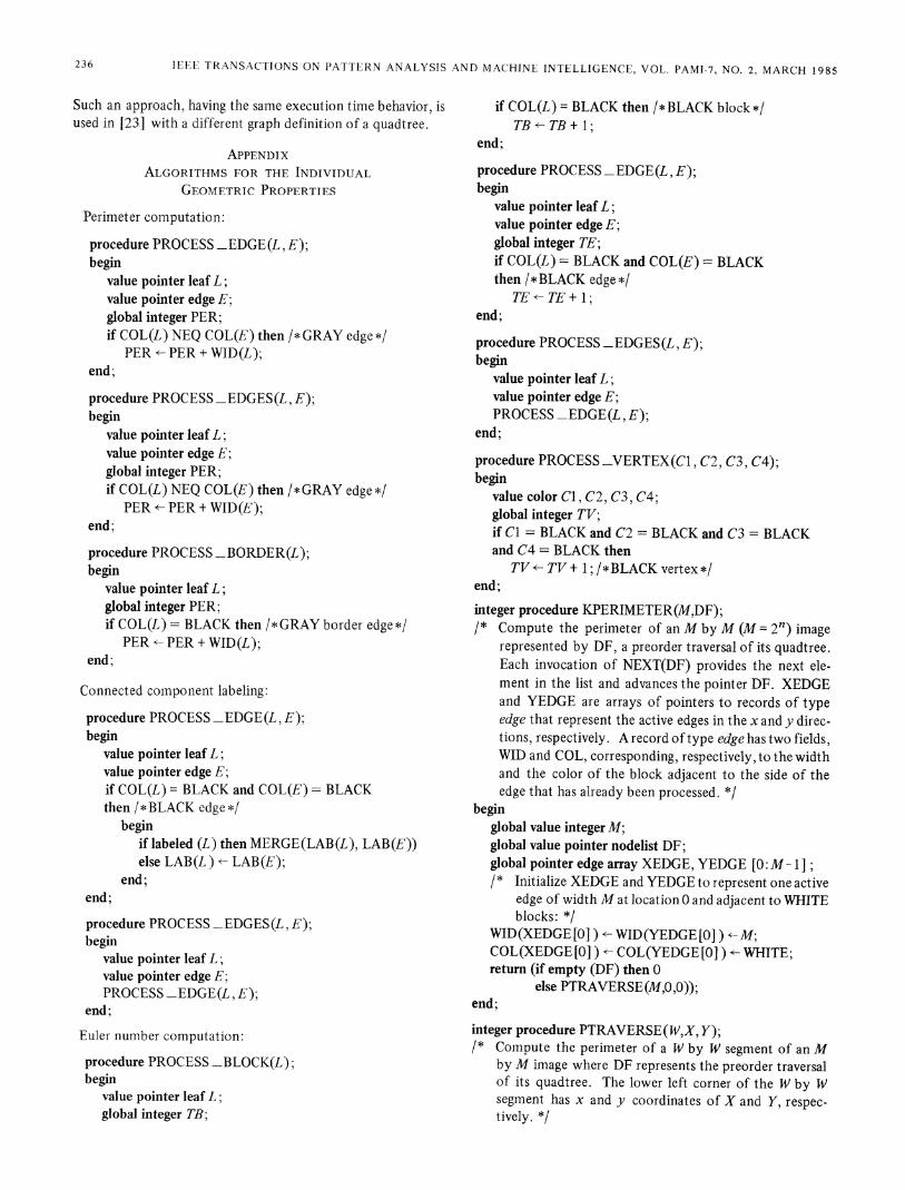
Fig. 3. Sample image containing two connected components.
tree traversal and updates the labels on the nodes to reflect theequivalences generated by the first two steps of the algorithm.Using our graph formulation of the quadtree, step one becomesa simple examination of all the BLACK edges. Steps two andthree are unchanged from the original formulation. The algo-rithm is given below by procedure CCL.
procedure CCL(Q);/* Label the connected components of quadtree Q. */begin
value quadtree Q;edge E;block B;foreach E in {edges(Q )} do
begin /* Step one */if BLACK(E) then ASSIGN_SAME_LABEL(TOUCH(E));
end;MERGE-EQUIVALENCES; /* Step two */foreach B in {blocks (Q)}do
begin /* Step three *lif BLACK(B) then UPDATE(B);
end;end;
Applying the algorithm to Fig. 3 yields two connected com-ponents. Note that the first and second steps can be combinedto form one step by using the UNION-FIND algorithm [25]thereby resulting in a two-step process. However, by separatingthese tasks we are better able to see the similarity between thealgorithms for the different geometric properties.The Euler number (or genus) of an image is the difference
between the number of connected components and the numberof holes. Dyer has shown that the Euler number of an imagerepresented by a quadtree is B - E + V [4] where B is thenumber of BLACK blocks, E is the number of pairs of adjacentBLACK blocks in the horizontal and vertical directions, and Vis the number of cases where three or four BLACK blocks sharea corner (i.e., there exists a 2 X 2 block of BLACK pixels suchthat at least three out of the four pixels are in different BLACKblocks). For example, for Fig. 3, B = 10, E= 10, and V= 1(contributed by vertex A) yielding a Euler number of 1. Thealgorithm is analogous to the first step of connected compo-nent labeling with the added provision that in order to deter-mine V, for each BLACK block, the leaf nodes surrounding itsSE corner must be examined as must vertices on its S and Wsides. For example, when processing node N of Fig. 2 we in-spect the leaves surrounding vertices AT, AP, and AU. Using
our graph formulation of the quadtree, we merely need toaccumulate the number of BLACK blocks, BLACK edges, andBLACK vertices. The algorithm is given below using procedureGENUS.
integer procedure GENUS(Q);/* Compute the genus of quadtree Q. *1begin
value quadtree Q;block B;edge E;vertex V;integer TB, TE, TV;TB÷- TE<-TV --0;foreach B in {blocks (Q )} do
beginif BLACK(B) then TB v TB + 1;
end;foreachE in {edges(Q)}do
beginif BLACK(E) then TE*- TE + 1;
end;foreach V in {vertices(Q)}do
beginif BLACK(V) then TV÷v TV+ 1;
end;return (TB - TE + TV);
end;
IV. COMPUTING PERIMETERS OF LINEAR QUADTREESRecall from Sections I and II that a linear quadtree represents
an image as a preorder traversal of the leaf nodes comprising it.The traversal of the blocks, edges, and vertices of the graph ofa quadtree described in Section II can be implemented by atraversal of the leaves of the tree. In this section, we showhow this can be achieved for the task of perimeter computationin such a way that each leaf node is examined exactly once.At any instant, the state of the traversal (i.e., after processingm leaf nodes) can be visualized as a staircase (termed an activeborder). The active border partitions the leaf nodes into twosets: those nodes that have already been visited and those thatare to be visited in the future. In particular, given a traversalin the order SW, SE, NW, NE, the part of the image describedby the m leaf nodes is to the left of and below the staircase.3The active border consists of a set of active edges. This set canbe decomposed into a set of active horizontal edges and activevertical edges. For example, for Fig. 1, a traversal in the aboveorder (without GRAY nodes) is L, M, J, 39, 40, 37, 38, 59,60, 57, 58, Q, N, 0, B, H, I, F, G. Fig. 4 shows the activeborder after processing node 37. In the following, we describea process that systematically visits the edges of the quadtreewithout requiring the use of neighbor finding methods that arebased on locating the nearest common ancestor [18] .From Section III we know that the computation of the
perimeter only requires the accumulation of the widths of all
3In fact, any traversal order that forms a staircase can be used withour algorithms once appropriate changes are made. Thus, for instance,the order SW, NW, NE, SE would also be permitted, as would others.
232
SAMET AND TAMMINEN: GEOMETRIC PROPERTIES OF LINEAR QUADTREE IMAGES
37
..................................~ ~ ~ ~ ~ .
Fig. 4. The active border after processing node 37 in Fig. 1.
GRAY edges. This process is facilitated by the active borderwhich records the color and size (i.e., width) of each leaf nodethat is adjacent to it. We represent the active border by twoarrays of active edges, termed XEDGE and YEDGE, corre-
sponding to the active horizontal and vertical edges and indexedby the x and y coordinates, respectively, of their starting pixels.This enables the cost of accessing the edge data structure to beindependent of the number of edges. XEDGE and YEDGE are
implemented as arrays of pointers to records of type edge.Each edge represents an active edge. It has two fields, WIDand COL, corresponding to the width and the color of theblock adjacent to the side of the edge that has already beenprocessed. Initially, there is one active horizontal edge andone active vertical edge, both of width 2' and color WHITE ataddress 0. For example, Fig. 4 shows the active border afterprocessing node 37, while Table I represents the state of theXEDGE and YEDGE arrays.
Perimeter computation is performed by procedures KPERIM-ETER, PTRAVERSE, and INCREMENT. They are given belowusing a variant of Algol. Procedure KPERIMETER is invokedwith the DF-expression encoding of the nodes in the quadtree.It initializes the active border and then invokes procedurePTRAVERSE, which controls the traversal of the quadtreenodes. For each leaf node, PTRAVERSE calls procedureINCREMENT twice, i.e., once for the southern side of a leafand once for the western side. INCREMENT augments theperimeter and updates the active border.
In order to see how INCREMENT works, suppose that we
are adding leaf node L of width W, color C, and leftmost pixelat x coordinate X. We illustrate the workings of INCREMENTwith respect to the southern side of L. Let the southern neigh-bor of L be Q. Note that at this point Q has already been pro-cessed, and so all the relevant data with respect to the edgesbetween L and Q are represented by XEDGE [X], i.e., theircolor and width. There are three possibilities. First, if Q is ofthe same size as L, and Q is a leaf node, then we simply checkif the edge is GRAY (i.e., L and Q differ in color along theirshared side). If yes, then the perimeter is augmented by W. Inany case, XEDGE [X] is updated to reflect the new activeedge, i.e., the northern side of L. As an example, after pro-
cessing leaf node 37 in Fig. 1, the perimeter is augmented by 1
corresponding to the width of leaf 37 (assuming an 8 X 8 pixelarray) since the edge between 37 and its southern neighbor,39, is GRAY. The color field of the active edge is changedfrom BLACK to WHITE because 37 is a WHITE leaf. Thewidth field remains the same in this case.
TABLE IXEDGE AND YEDGE AFTER PROCESSING NODF 37 IN FIG. I
XEDGE [I ] YEDGE [I]_I.
LEN COL BLOCK LEN COL BLOCK
0 2 WHITE J 2 BLACK M
2 WHITE 37 BLACK 40
3 BLACK 40 WHITE 37
4 4 WHITE BORDER 4 WHITE BORDER5
67 __ _ _ _ _ _ _ _ _ _ _ _ _ _ _ _
Second, if Q is larger than L, then Q must correspond to aleaf node. If the edge between L and Q is GRAY, then theperimeter is augmented by W. In any case, XEDGE [X] is up-dated to reflect the two new active edges. In particular,XEDGE [X] is set to the northern side of L. In addition, thereis a new segment of the active border that corresponds to thepart of the active edge associated with Q that has not been re-placed by the northern side of L. As an example, after pro-cessing leaf node 39 in Fig. 1, the perimeter is unchanged sincethe edge between it and its southern neighbor, M, is BLACK.The color field of the active edge at XEDGE[2] remainsBLACK, but the width field is changed from 2 to 1. SinceMis larger than 39, the part of the active border between pixellocations 3 and 4 now forms an active edge. In particular,the color field of XEDGE[3] is set to BLACK, and its widthfield is set to 1.Third, if Q is of the same size as L but corresponds to a GRAY
node (i.e., WID(XEDGE [XJ) < W), then we must process allof the edges between L and the northernmost descendants ofQ. For each such edge that is GRAY, the perimeter is aug-mented by the width of the adjacent northernmost descendantof Q. In any case, XEDGE [X] is updated to reflect the newactive edge, i.e., the northern side of L. As an example, in Fig.1 the southern neighbor of leaf nodeB is GRAY node D. Afterprocessing B, the perimeter is augmented by 1 correspondingto the width of node 38 since it is the only northernmostdescendant of D that has a GRAY edge between it and B. Thecolor field of the active edge (i.e., XEDGE [0] ) remains WHITE.The width field of the active edge is set to 4 (i.e., XEDGE [0] ).Procedure INCREMENT must also do some extra work
when processing a node adjacent to the border of the image.In particular, it must determine if the edge formed by theblock and the border is GRAY (assuming that the image is sur-rounded by WHITE). For example, after processing node I inFig. 1 we are at the eastern border of the image. This is de-tected after the application of INCREMENT to the southernside of I since the x coordinate of the westernmost pixel ofIis available for such a test. In this example, the edge is GRAY,and the perimeter is augmented by 2 (i.e., the width of I).
V. A GENERAL GEOMETRIC PROPERTY COMPUTATIONALGORITHM
In Section IV we saw how to compute the perimeter of animage represented by a linear quadtree. This was facilitated
233
IEEE TRANSACI-IONS ON PATITERN ANALYSIS AND MACHINE INTELLIGENCE, VOL. PAMI-7, NO. 2, MARCH 1985
by use of a data structure which was called an active border.In this section we show how additional geometric propertiessuch as the Euler number and connected component labelingcan be computed for linear quadtrees. This is done in the con-text of a general algorithm which is able to compute all threegeometric properties. In the process we show how the activeborder data structure is modified to enable the computationof these properties.The algorithms that we study are of two types: those that
are based solely on the inspection of adjacencies at edges andthose that also require the inspection of adjacencies at vertices.Computation of perimeter and connected components are ofthe former type, while the computation of the Euler numberis of the latter type. In order to label connected components,we need only add a field to the active border data structurethat records the label assigned to the block adjacent to the sideof the edge that has already been processed. Thus, the edgerecord type now contains an additional field termed LAB.The computation of the Euler number requires an additional
data structure to keep track of the vertices. To see this, wenote that for each leaf, say L, of the preorder traversal, wemust determine if the SW vertex of L, say X, is BLACK. Thisis the last opportunity to examine this vertex since it will neveragain be adjacent to the active border. This statement is easilyverified by observing the staircase nature of the active borderand the fact that the tree is traversed in the order SW, SE, NW,NE. In other words, the active border expands in the rightwardand upward directions. The active border data structure usedfor computing perimeter and connected components does notalways contain enough information to dctermine the color ofX. In particular, it only keeps track of the colors of the leafnodes that are adjacent to the border along a side and not at acorner. For example, Fig. 4 and Table I show the active borderafter processing node 37 in Fig. 1. The next node to be pro-cessed is 38, but we do not know the color of the block adja-cent to its SW corner. To rectify this situation, we define anadditional entity termed an active vertex, which correspondsto a vertex on the active border. The set of all such -vertices iscalled the active vertices. It is implemented as an array, VRTX,of pointers to records of type vertex. A record of type vertexhas one field, COL, corresponding to the color of the blockwhose NE corner touches the vertex. For a 2n' X 2' imagearray, at any one time, VRTX has a maximum of 2n+ 1-entries. Given a vertex at (x,y), VRTX[x - y] corresponds toits vertex record. Since the line K = x - y can only intersectthe active border at one position, we see that no two activevertices may simultaneously have the same VRTX entry.The general geometric property computation algorithm can
be decomposed into two setF of procedures. The first setconsists of procedures GEOM_PROPERTY, TRAVERSE,PROCESS-LEAF, PROCESS SIDE, UPDATE_VERTEX,and UPDATE-EDGE. They are common to the computationof all geometric properties. The actual computation is con-trolled by procedure GEOM_PROPERTY, which is invokedwith the DF-expression encoding of the nodes in the quadtree.It initializes the active border and the active vertices and theninvokes procedure TRAVERSE, which controls the traversalof the quadtree nodes. For each leaf node, TRAVERSE calls
procedure PROCESS-LEAF to compute the desired geometricproperty. PROCESS-LEAF invokes procedure PROCESS_SIDE twice: once for the southern border and once for thewestern border. Procedures UPDATE-VERTEX andUPDATE-EDGE are used to update the active vertices andactive border, respectively. TRAVERSE assumes that thelinear quadtree is in the form of a DF-expression. However, itshould be clear that TRAVERSE could be easily modified tohandle other linear quadtree representations. Note that wemake use of a record of type leaf to represent the leaf nodes.It is an edge record with two additional fields, XPOS and YPOS,corresponding to the coordinates of the lower left-hand cornerof the leaf.The second set consists of procedures necessary to compute
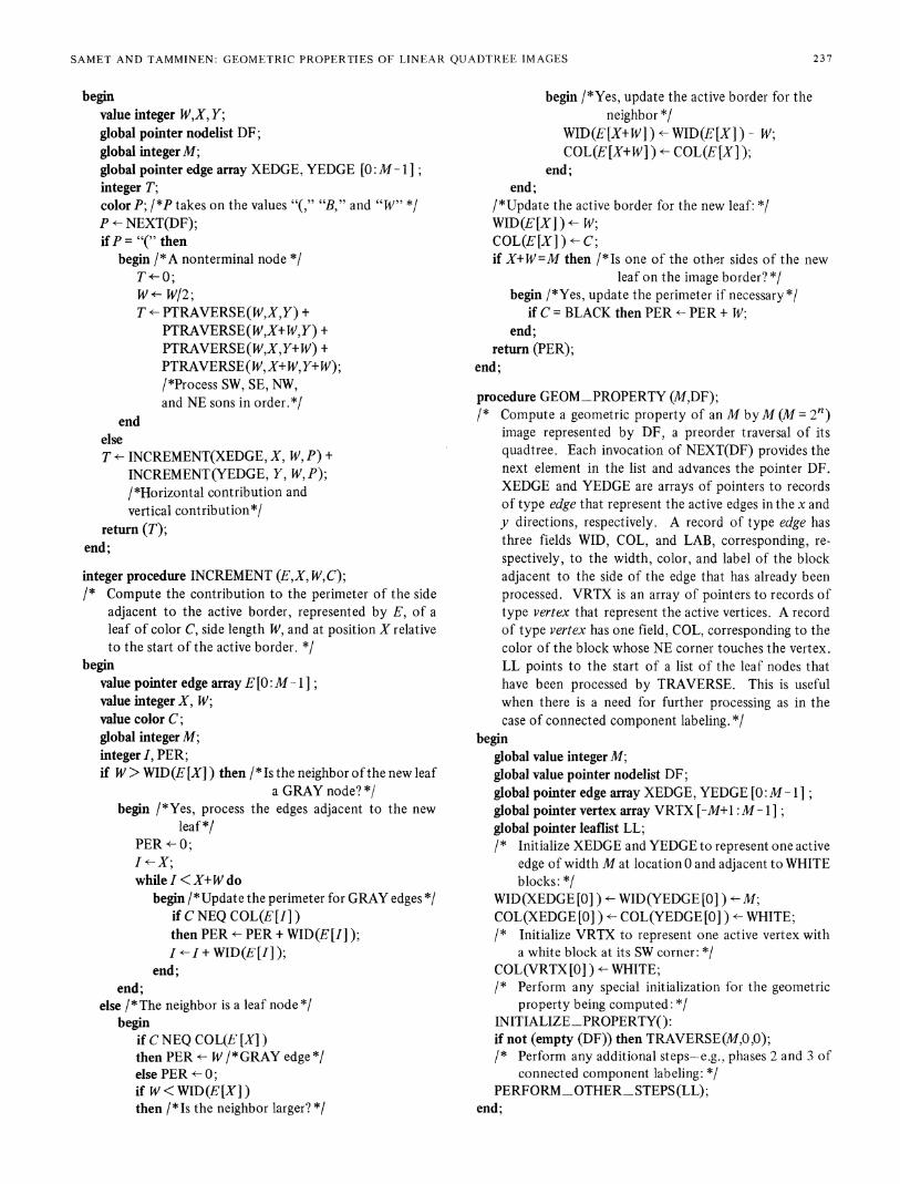
the geometric property in question and thus may be codeddifferently depending on the geometric property. It consistsof procedures PROCESS_VERTEX, PROCESS-BLOCK,PROCESS-EDGE, PROCESS-EDGES, and PROCESS_BORDER. The actual code for these procedures is given in theAppendix for the computation of perimeter, connected com-ponent labeling, and Euler number. In the following we de-scribe briefly their meaning. Note that for a specific geometricproperty not all of the procedures are used.Procedure PROCESS-LEAF is the controller of the com-
putation process. For each leaf node, say L, it Derforms thefollowing three steps. First, the vertex in which the SW cornerof L participates as an NE component is now fully specified(i.e., the colors of the blocks touching it are all known), and itis processed by PROCESS_VERTEX. This is useful in thecomputation of the Euler number. We also use UPDATE_VERTEX to update the VRTX entry corresponding to the NEcorner of L (e.g., after processing leaf node G in Fig. 1, thecolor of the active vertex corresponding to the NE corner of Gis changed to WHITE from BLACK, which was the color asso-ciated with the previous VRTX entry, i.e., corresponding tothe NE corner of H). Second, PROCESS-SIDE is invokedtwice: once to process all the edges and vertices on the W sideof L and once for those on the S side. Finally, PROCESS_BLOCK is invoked to perform any computation that involvesthe leaf node alone. For example, when computing the Eulernumber we must keep track of the number of BLACK leafnodes.Procedure PROCESS-SIDE has the same structure as pro-
cedure INCREMENT described in Section IV for the computa-tion of perimeter. Suppose that we are adding leaf node L ofwidth W, color C, and leftmost pixel at x coordinate X. As-sume that we are processing the southern side of L and let Qbe the southern neighbor of L (recall the definition of neighborin Section II). PROCESS_SIDE must process the edges andvertices between Q and L depending on their relative sizes.This is described below. In addition, it updates the activeborder for the northern side of the new leaf L by use ofUPDATE-EDGE. Finally, it checks to see if the eastern sideof the new leaf is on the border, in which case it invokesPROCESS-BORDER to perform any necessary additionalcomputations (e.g., for perimeter).When processing the edges and vertices lying between Q and
L, there are three possibilities. First, if Q is of the same size as
234
SAMET AND TAMMINEN: GEOMETRIC PROPERTIES OF LINEAR QUADTREE IMAGES
L, and Q is a leaf node, then we simply compute the geometricproperty for the edge between L and Q using PROCESS_EDGE.Second, if Q is larger than L, then Q must correspond to a leafnode. Again, we compute the geometric property for the edgebetween L and Q using PROCESS_EDGE. In addition, we
invoke UPDATE_VERTEX and UPDATE_EDGE to updatethe active vertices and active border data structures, respec-
tively, to reflect the additional vertex and the reduction in sizeof a component of the active border. As an example, after pro-
cessing leaf node 39 in Fig. 1, we find that the size of the con-
tribution of M to the active border changes from 2 to 1 andlies between pixel positions 3 and 4. Moreover, there is now a
vertex at (3, 2), and the set of active vertices is modified ac-
cordingly. Third, if Q is of the same size as L but correspondsto a GRAY node, then we compute the geometric property forthe edges and vertices between L and the northernmost de-scendants of Q. This is done by PROCESS_EDGES andPROCESS_VERTEX. Note that this is the last time that we
have an opportunity to examine these edges and vertices sincethey will never again be adjacent to the active border. As an
example, in Fig. 1 the southern neighbor of leaf node B isGRAY node D. From Fig. 3 we see that we must compute thegeometric property for edges xf, xg, and xh and vertices AIand AJ.The detailed code for procedures PROCESS VERTEX,
PROCESS-BLOCK, PROCESS-EDGE, PROCESS-EDGES,and PROCESS-BORDER for each geometric property, whenthey are used, is given in the Appendix. For perimeter compu-
tation, PROCESS-EDGE and PROCESS-EDGES check forGRAY edges. Assuming that the image is surrounded byWHITE, PROCESS-BORDER determines if the border edgeis GRAY. PROCESS-VERTEX and PROCESS-BLOCK are
not used.For connected component labeling, PROCESS-EDGE and
PROCESS-EDGES check for BLACK edges and merge ifnecessary. PROCESS_VERTEX, PROCESS_BLOCK, andPROCESS BORDER are not used.For Euler number computation, PROCESS EDGE and
PROCESS EDGES check for BLACK edges. PROCESSVERTEX checks for BLACK vertices. PROCESS BLOCKchecks for BLACK leaf nodes. PROCESS BORDER is notused.
VI. CONCLUDING REMARKS
A general algorithm for the computation of geometric prop-erties for images represented by linear quadtrees has beenpresented. The key to the success of the algorithm is the use
of a staircase-like data structure to represent the active borderas the tree is traversed. Use of a graph-theoretic definition ofa quadtree simplified the presentation considerably. The algo-rithm was discussed in the context of a linear quadtree repre-sentation in the form of a DF-expression. However, it shouldbe clear that it can be used with other linear quadtree repre-sentations. No general algorithms for such tasks using linearquadtrees have existed before.Computation of the perimeter and the Euler number only
requires one pass over the data whereas connected componentlabeling requires two passes (one for determining equivalences
and one for updating; recall that steps one and two can becombined). The execution time of perimeter, Euler number,and the first step of connected component labeling using ourgeneral algorithm is proportional to the number of leaf nodesin the image. This is better than results achievable by algo-rithms based on neighbor finding using a nearest commonancestor. The problem with the latter is that although theyhave linear average case behavior, in the worst case, even assum-ing an explicit tree representation, their execution time is pro-portional to T - n where T is the number of leaf nodes in a2n X 2' image. The worst case for nearest common ancestorneighbor finding methods arises when the nearest commonancestor is the root of the tree. For example, in Fig. 1, to lo-cate the eastern neighbor of node 38 (i.e., N), we must ascendthrough K, D, and A and descend to N through E. For a moregeneral example of this worst case behavior, see [20] . Notealso that Jackins and Tanimoto [8] have devised an O(T) pe-rimeter computation algorithm applicable to explicit quadtreerepresentations. However, their algorithm traverses the quad-tree twice, whereas we only need to traverse it once.Using our algorithms, the amount of extra storage beyond that
required for the quadtree nodes is three arrays. We assume a2n X 2n image. Two of the arrays are used for the active border,have a maximum of 2n entries, and contain three fields perentry (i.e., WID, COL, and LAB). The third array for the activevertices has a maximum of 2n+i - 1 entries and contains onefield per entry. The active border and active vertices data struc-tures could also be implemented as linked lists with a slightlymore complex access mechanism. This would have the advan-tage of not needing to store more entries than there are actualedges and vertices. The quadtree nodes are stored in externalmemory. However, it is preferable to store the active borderand vertices arrays in internal memory.The algorithms presented in this paper were tried out on an
existing geographic information system based on linear quad-trees [15]. Due to the large amount of data, the system isdisk based. Use of the new algorithm resulted in an order ofmagnitude improvement in the execution time of algorithmssuch as perimeter computation. Aside from the decrease in thecomputational complexity of the new algorithm, other reasonsfor the speed-up include the absence of page faults due to theability to process the nodes of the quadtree in a sequential or-der. In experiments involving trees stored in central memory,the speed-up was smaller but still considerable (up to sixfold).However, we refrain from giving exact figures due to the greatdependence of the performance of the Gargantini encodingscheme [5] on implementation details.Future work includes an attempt to compute distance trans-
forms [19] and a quadtree medial axis transform [211 usinglinear quadtrees. This is somewhat more difficult than the algo-rithms which we have attempted above since we must examineall sides of a leaf node as well as neighbors of neighbors. Mostlikely, such tasks will require more than one pass over the leafnodes comprising the linear quadtree. Geometric propertiesfor linear octrees [6] (e.g., connected component labeling, sur-face area, etc.) could also be computed using similar techniques.However, the active border and active vertices arrays will nowget rather large, and it would be preferable to use linked lists.
235
IEE2E TRANSACTIONS ON PATTERN ANALYSIS AND MACHINE INTELLIGENCE, VOL. PAMI-7, NO. 2, MARCH 1985
Such an approach, having the same execution time behavior, isused in [23] with a different graph definition of a quadtree.
APPENDIXALGORITHMS FOR THE INDIVIDUAL
GEOMETRIC PROPERTIES
Perimeter computation:
procedure PROCESS -EDGE (L, E);begin
value pointer leaf L;value pointer edge E;global integer PER;if COL(L) NEQ COL(E) then 7* GRAY edge */
PER <- PER + WID(L);end;
procedure PROCESS EDGES(L, E);begin
value pointer leaf L;value pointer edge E;global integer PER;if COL(L) NEQ COL(E) then /*GRAY edge*7PER *- PER + WID(E);
end;
procedure PROCESS BORDER(L);begin
value pointer leaf L;global integer PER;if COL(L) = BLACK then /* GRAY border edge *7PER <- PER + WID(L);
end;
Connected comnponent labeling:
procedure PROCESS EDGE(L, E);begin
value pointer leaf L;value pointer edge E;if COL(L) = BLACK and COL(E) = BLACKthen /*BLACK edge *7
beginif labeled (L) then MERGE(LAB(L), LAB(E))else LAB(L) -- LAB(E);
end;end;
procedure PROCESS _EDGES(L, E);begin
value pointer leaf L;value pointer edge E;PROCESS _EDGE(L, E);
end;
Euler number computation:
procedure PROCESS BLOCK(L);begin
value pointer leaf L;global integer TB;
if COL(L) = BLACK then /*BLACK block*TB TB + 1;
end;procedure PROCESS -EDGE (L, E);begin
value pointer leaf L;value pointer edge E;global integer TE;if COL(L) = BLACK and COL(E) = BLACKthen /*BLACK edge *7
TE <- TE+ 1;end;
procedure PROCESS EDGES (L, E);begin
value pointer leaf L;value pointer edge E;PROCESS EDGE(L, E);
end;
procedure PROCESS VERTEX(C1, C2, C3, C4);begin
value color Cl, C2, C3, C4;global integer TV;if Cl = BLACK and C2 = BLACK and C3 = BLACKand C4 = BLACK thenTV - TV + 1;/*BLACK vertex*/
end;integer procedure KPERIMETER(M,DF);/* Compute the perimeter of an M by M (M = 2f) image
represented by DF, a preorder traversal of its quadtree.Each invocation of NEXT(DF) provides the next ele-ment in the list and advances the pointer DF. XEDGEand YEDGE are arrays of pointers to records of typeedge that represent the active edges in the x and y direc-tions, respectively. A record oftype edge has two fields,WID and COL, corresponding, respectively, to the widthand the color of the block adjacent to the side of theedge that has already been processed. *7
beginglobal value integer M;global value pointer nodelist DF;global pointer edge array XEDGE, YEDGE [0:M 1 ];/* Initialize XEDGE and YEDGE to represent one active
edge of widthM at location 0 and adjacent to WHITEblocks: */
integer procedure PTRAVERSE(W,X, Y);/* Compute the perimeter of a W by W segment of an M
by M image where DF represents the preorder traversalof its quadtree. The lower left corner of the W by Wsegment has x and y coordinates of X and Y, respec-tively. */
236
SAMET AND TAMMINEN: GEOMETRIC PROPERTIES OF LINEAR QUADTREE IMAGES
beginvalue integer W,X, Y;global pointer nodelist DF;global integer M;global pointer edge array XEDGE, YEDGE [0:M - I;integer T;color P; /*P takes on the values "(," "B," and "W" */P <- NEXT(DF);ifP = "(" then
begin /*A nonterminal node */To 0;W- W/2;T v- PTRAVERSE(W,X,Y) +
PTRAVERSE(W,X+W,Y) +PTRAVERSE(W,X,Y+W) +PTRAVERSE(W, X+W,Y+W);/*Process SW, SE, NW,and NE sons in order.*/
endelseT *- INCREMENT(XEDGE, X, W, P) +
INCREMENT(YEDGE, Y, W,P);/*Horizontal contribution andvertical contribution*/
return (T);end;
integer procedure INCREMENT (E,X, W,C);/* Compute the contribution to the perimeter of the side
adjacent to the active border, represented by E, of aleaf of color C, side length W, and at position X relativeto the start of the active border. */
beginvalue pointer edge array E [0:M - 1];value integer X, W;value color C;global integer M;integer I, PER;if W> WID(E[X]) then /*Is the neighbor ofthe new leaf
a GRAY node? */begin /*Yes, process the edges adjacent to the new
leaf *1PER <- 0;I-X;while I <X+W do
begin /*Update the perimeter for GRAY edges */if C NEQ COL(E[I])then PER e- PER + WID(E [I]);I*-I+ WID(E[I]);
end;end;
else /*The neighbor is a leaf node *1begin
if C NEQ COL(E [X])then PER *- W / *GRAY edge *1else PER +- 0;if W<WID(E[X])then /*Is the neighbor larger? */
begin /*Yes, update the active border for theneighbor */
WID(E[X+W ) e- WID(E[X]) W;COL(E[X+W]) v COL(E[X]);
end;end;
/*Update the active border for the new leaf: *7WID(E[X] ) <- W;COL(E[X]) C;if X+W=M then /*Is one of the other sides of the new
leaf on the image border? */begin /*Yes, update the perimeter if necessary*/
if C = BLACK then PER <- PER + W;end;
return (PER);end;
procedure GEOM_PROPERTY (M,DF);/* Compute a geometric property of an M byM (M = 2f)
image represented by DF, a preorder traversal of itsquadtree. Each invocation of NEXT(DF) provides thenext element in the list and advances the pointer DF.XEDGE and YEDGE are arrays of pointers to recordsof type edge that represent the active edges in the x andy directions, respectively. A record of type edge hasthree fields WID, COL, and LAB, corresponding, re-spectively, to the width, color, and label of the blockadjacent to the side of the edge that has already beenprocessed. VRTX is an array of pointers to records oftype vertex that represent the active vertices. A recordof type vertex has one field, COL, corresponding to thecolor of the block whose NE corner touches the vertex.LL points to the start of a list of the leaf nodes thathave been processed by TRAVERSE. This is usefulwhen there is a need for further processing as in thecase of connected component labeling. *7
beginglobal value integer M;global value pointer nodelist DF;global pointer edge array XEDGE, YEDGE [0:M 1];global pointer vertex array VRTX [-M+ :M 1];global pointer leaflist LL;/* Initialize XEDGE and YEDGE to represent one active
edge of width M at location 0 and adjacent to WHITEblocks: */
WID(XEDGE [0] ) - WID(YEDGE [0]) M;COL(XEDGE [0]) <- COL(YEDGE [0]) e WHITE;/* Initialize VRTX to represent one active vertex with
a white block at its SW corner: *1COL(VRTX [0] ) <- WHITE;/* Perform any special initialization for the geometric
property being computed: */INITIALIZE PROPERTYo:if not (empty (DF)) then TRAVERSE (M,0,0);/* Perform any additional steps-e.g., phases 2 and 3 of
IEEE TRANSACTIONS ON PATTERN ANALYSIS AND MACHINE INTELLIGENCE, VOL. PAMI-7, NO. 2, MARCH 1985
procedure TRAVERSE(W,X,Y);/* Compute a geometric property of a W by W segment of
an M byM image where DF represents the preorder tra-versal of its quadtree. The lower left corner of the Wby W segment has x and y coordinates of X and Y, re-spectively. For each leaf node, procedure PROCESS_LEAF is invoked to perform the appropriate computa-tion. After processing each leaf node, it is added to alist, LL, of records of type leaf each of which has fivefields, WID, COL, LAB, XPOS, and YPOS correspondingto the width of its side, color, label, and x and y coor-dinates of its lower left corner, respectively.*/
beginvalue integer W, X, Y;global pointer nodelist DF;global integer M;global pointer edge array XEDGE, YEDGE [0:M 1];global pointer vertex array VRTX [-M+1:M - 1];global pointer leaflist LL;color P; /*P takes on the values "(," "B," and "W" */pointer leaf L;P <- NEXT(DF);If P = "(" then
begin /*Nonleaf node */W* W/2;TRAVERSE(W,X,Y);TRAVERSE(W,X+W,Y);TRAVERSE(W,X,Y+W);TRAVERSE(W,X+W,Y+W);/*Process SW, SE, NW,and NE sons*/
X - XPOS(L); /*Unpack some of the fields of the leafL*/
Y e YPOS(L);W - WID(L);C - COL(L);/* Process the SW vertex of L, i.e., the colors of all the
leaf nodes surrounding it are now known and its colorcan be determined: */
PROCESS VERTEX(C,COL(VRTX[X- Y]),COL(XEDGE[X] ),COL(YEDGE[Y] ));
/* Update the VRTX entry corresponding to the NEcorner of L: */
UPDATE_VERTEX(X- Y,L);/* Process all the edges and vertices on the S side of
L: */PROCESS-SIDE(XEDGE,X,X+W Y,L);/* Process all the edges and vertices on the W side of L: */PROCESS_SIDE(YEDGE,Y,X- Y- W,L);/* Process the block corresponding to the leaf L: */PROCESS_BLOCK(L);
end;
procedure PROCESS_SIDE(E,X,V,L);/* Determine the contribution of a side of the new leaf L
(side width W and color C) to the geometric propertybeing computed. The segment of the active border thatis adjacent to the side is represented by E starting at en-try X. V is the index of the active vertices data structure(i.e., VRTX) that corresponds to the vertex at pixelX+W. V is used in UPDATE_VERTEX. */
beginvalue pointer edge array E [0:M - 1];value integer X,V;value pointer leaf L;global integer M;integer I, VI, W;W <- WID(L);if W>WID(E[X])then /*Is the neighbor of the new leaf a GRAY node? */
begin /*Yes, process the edges adjacent to the newleaf */
PROCESS EDGES(L ,E[X]);VI--X;I-X + WID(E[X]);while I < X+W do
begin /*Compute the geometric property forGRAY edges */
SAMET AND TAMMINEN: GEOMETRIC PROPERTIES OF LINEAR QUADTREE IMAGES
if W<WID(E[X])then /*Is the neighbor larger? */
begin /*Yes, update the active border and vertexfor the neighbor: */
UPDATE EDGE(E[X+W] W,E[X]);UPDATE_VERTEX(V,E[X]);
end;end;
/* Update the active border for the new leaf */UPDATE_EDGE(E[X], W,L);ifX+W =M then /* Is the other side of the new leaf on
the image border? */PROCESS_BORDER(L);/*Yes, update the geometric prop-
erty if necessary*/end;
procedure UPDATE_VERTEX(V,EL);/* Set the color of the Vth entry of vertex array VRTX to
the color associated with edge or leaf EL. The argumentEL may be a pointer to an edge or a leaf since a leaf isan edge record which also has entries for the coordinatesof its lower left pixel. */
procedure UPDATE_EDGE(E,D,EL);/* Update the active border for edge E to reflect the ad-
jacency to leaf EL. This procedure is also used to up-date the neighbor to a leaf in which case the WID fieldis modified by D and EL is a pointer to an edge. This ispermissible since a leaf is an edge record which also hasentries for the coordinates of its lower left pixel.
The authors thank Prof. R. Sulonen for his comments, andC. Shaffer and E. Haataja for their assistance in enabling us tomake empirical observations.
REFERENCES
[1 ] D. J. Abel and J. L. Smith, "A data structure and algorithm basedon a linear key for a rectangle retrieval problern," Comput. Vision,Graphics, Image Processing, vol. 24, no. 1, pp. 1-13, Oct. 1983.
[21 F. W. Burton and J. G. Kollias, "Comment on the explicit quad-tree as a structure for computer graphics," Comput. J., vol. 26,no. 2, p. 188, May 1983.
[31 B. G. Cook, "The structural and algorithmic basis of a geographicdata base," in Proc. 1st Int. Advanced Study Symp. Topol. DataStructures Geogr. Inform. Syst., G. Dutton, Ed., Harvard Paperson Geographic Information Systems, 1978.
[41 C. R. Dyer, "Computing the Euler number of an image from itsquadtree," Comput. Graphics Image Processing, vol. 13, no. 3,pp. 270-276, July 1980.
[51 I. Gargantini, "An effective way to represent quadtrees," Com-mun. ACM, vol. 25, no. 12, pp. 905-910, Dec. 1983.
[61 , "Linear octtrees for fast processing of three dimensional ob-jects," Comput. Graphics Image Processing, vol. 20, no. 4, pp.365-374, Dec. 1982.
[7 CG. M. Hunter and K. Steiglitz, "Operations on images using quad-trees," IEEE Trans. Pattern Anal. Mach. Intell., vol. PAMI-1, pp.145-153, Apr. 1979.
[81 C. Jackins and S. L. Tanimoto, "Quad-trees, oct-trees, and k-trees-A generalized approach to recursive decomposition of Euclideanspace," IEEE Tranis. Pattern Anal. Mach. Intell., vol. PAMI-5,pp. 533-539, Sept. 1983.
[91 E. Kawaguchi and T. Endo, "On a method of binary picture repre-sentation and its application to data compression," IEEE Trans.Pattern Anal. Mach. Intell., vol. PAMI-2, pp. 27-35, Jan. 1980.
[101 E. Kawaguchi, T. Endo, and J. Matsunaga, "Depth-first expres-sion viewed from digital picture processing," IEEE Trans. PatternAnal. Macli. Intell., vol. PAMI-5, pp. 373-384, July 1983.
[11l A. Klinger, "Patterns and search statistics," in OptimizingMethodsin Statistics, J. S. Rustagi, Ed. New York: Academic, 1971, pp.303-337.
[121 A. Klinger and M. L. Rhodes, "Organization and access of imagedata by areas," IEEE Trans. Pattern Anal. Mach. Intell., vol.PAMI-1, pp. 50-60, Jan. 1979.
[131 G. M. Morton, "A computer oriented geodetic data base and anew technique in file sequencing," IBM Canada, 1966.
[14] M. A. Oliver and N. E. Wiseman, "Operations on quadtree-encodedimages," Comput. J., vol. 26, no. 1, pp. 83-91, Feb. 1983.
[151 A. Rosenfeld, H. Samet, C. Shaffer, and R. E. Webber, "Applica-tion of hierarchical data structures to geographical informationsystems phase II," Dep. Comput. Sci., Univ. Maryland, CollegePark, Tech. Rep. TR 1327, Sept. 1983.
[16 H. Samet, "Connected component labeling using quadtrees,"J. ACM, vol. 28, no. 3, pp. 487-501, July 1981.
[171] , "Computing perimeters of images represented by quadtrees,"IEEE Trans. Pattern Anal. Mach. Intell., vol. PAMI-3, pp. 683-687, Nov. 1981.
[181 "Neighbor finding techniques for images represented by quad-trees," Comput. Graphics Image Processing, vol. 18, no. 1, pp. 37-57, Jan. 1982.
[19] , "Distance transform for images represented by quadtrees,"IEEE Trans. Pattern Anal. Mach. Intell., vol. PAMI4, pp. 298-303, May 1982.
[20] , "A top-down quadtree traversal algorithm," IEEE Trans.Pattern Anal. Mach. Intell., vol. PAMI-7, pp. 94-98, Jan. 1985.
[211 , "A quadtree medial axis transform," Commun. ACM, vol.26, no. 9, pp. 680-693, Sept. 1983.
[221 -, "The quadtree and related hierarchical data structures," ACMComput. Surv., vol. 16, no. 2, June 1984.
[23] H. Samet and M. Tamminen, "Efficient image component label-ing," Dep. Comput. Sci., Univ. Maryland, College Park, Tech.Rep. TR 1420, June 1984.
[241 M. Tamminen, "Encoding pixel trees," Comput. Vision, Graphics,Image Processing, vol. 28, no. 1, pp. 44-57, Oct. 1984.
[251 R. E. Tarjan, "Efficiency of a good but not linear set union algo-rithm," J. ACM, vol. 22, no. 2, pp. 215-225, Apr. 1975.
[26] W. Weber, "Three types of map data structures, their ANDs andNOTs, and a possible OR," in Proc. 1st Int. Advanced StudySymp. Topol. Data Structures Geog. Inform. Syst., G. Dutton,Ed., Harvard Papers on Geographic Information Systems, 1978.
[271 J. R. Woodwark, "The explicit quadtree as a structure for com-puter graphics," Comput. J., vol. 25, no. 2, pp. 235-238, May1982.
239
IEEE TRANSACTIONS ON PATTERN ANALYSIS AND MACHINE INTELLIGENCE, VOL. PAMI-7, NO. 2, MARCH 1985
Hanan Samet (S'70-M'75) received the B.S.degree in engineering from the University ofCalifornia, Los Angeles, and the M.S. degree inoperations research and the M.S. and Ph.D. de-grees in computer science from Stanford Univer-sity, Stanford, CA.In 1975 he joined the University of Maryland,
College Park, as an Assistant Professor of Com-puter Science. In 1980 he became an AssociateProfessor. His research interests are data struc-tures, image processing, programming languages,
artificial intelligence, and database management systems.Dr. Samet is a member of the Association for Computing Machinery,
SIGPLAN, Phi Beta Kappa, and Tau Beta Phi.
Markku Tamminen (M'83) received the M.Sc.degree in applied mathematics in 1966 from theUniversity of Helsinki, Finland, and the Ph.D.degree in computer science from the HelsinkiUniversity of Technology in 1982.He has been with the Laboratory of Infor-
mation Processing Science, Helsinki Universityof Technology, since 1980 and is currently Headof a research project on geometric data struc-tures, funded by the Finnish Academy. From1973 to 1980 he was Chief Mathematician at
the Data Center of the Helsinki Metropolitan Area. His research interestsinclude data structures based on address computation, computationalgeometry, image data structures and algorithms, computer aided de-sign, and the management of spatially referenced data.Dr. Tamminen is a member of the Association for Computing Ma-
chinery, the IEEE Computer Society, and the Operations ResearchSociety of America.