37
com.tom PORTAL Cloud data logger solution for localization, monitoring and control of decentralized systems. com.tom PORTAL v2.1.2 Manual v1.21 English 14.10.2015
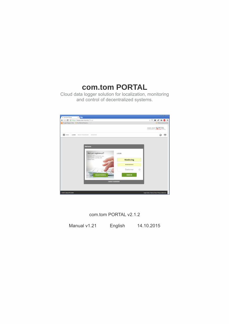
com.tom PORTAL Cloud data logger solution for localization, monitoring
and control of decentralized systems.
com.tom PORTAL v2.1.2
Manual v1.21 English 14.10.2015
com.tom PORTAL v2.1.2 – Manual EN v1.21 – 14.10.2015
2
Contents I. Introduction ............................................................................................................... 5
I. Requirements .......................................................................................................... 5
1. Gateways......................................................................................................................... 5
2. com.tom PORTAL web interface ..................................................................................... 5
II. Service Level Agreement ........................................................................................ 5
1. Availability ........................................................................................................................ 5
2. Quality ............................................................................................................................. 6
II. Support ....................................................................................................................... 7
I. Hotline and fault desk .............................................................................................. 7
1. Hotline ............................................................................................................................. 7
2. Fault desk ........................................................................................................................ 7
III. Getting Started ........................................................................................................... 8
I. Important terms ....................................................................................................... 8
II. Recurring symbols/icons ......................................................................................... 8
III. Tooltip system ......................................................................................................... 9
IV. URL Structure .......................................................................................................... 9
V. Registering ............................................................................................................ 10
1. Registering a Beck customer in the com.tom PORTAL ................................................. 10
2. Registering a new user .................................................................................................. 10
VI. Login .................................................................................................................... 11
VII.Setting the Language and Time Zone .................................................................. 11
1. Via the user menu ......................................................................................................... 11
2. Via the user settings ...................................................................................................... 11
3. As administrator............................................................................................................. 12
IV. View .......................................................................................................................... 13
I. Menu bars ............................................................................................................. 13
1. Main menu ..................................................................................................................... 13
2. Submenu ....................................................................................................................... 14
3. Sidebar .......................................................................................................................... 14
4. User menu ..................................................................................................................... 14
II. Page areas ............................................................................................................ 15
1. Header area................................................................................................................... 15

com.tom PORTAL v2.1.2 – Manual EN v1.21 – 14.10.2015
3
2. Content area .................................................................................................................. 15 a) Content box ............................................................................................................................. 15
V. Setup ........................................................................................................................ 16
I. Editing your own user ............................................................................................ 16
II. Creating editing and deleting other users .............................................................. 16
1. Managing user rights ..................................................................................................... 16
III. Creating a project .................................................................................................. 19
IV. Managing gateways .............................................................................................. 19
1. Creating a gateway........................................................................................................ 19
2. Editing a gateway .......................................................................................................... 20
3. Deleting a gateway ........................................................................................................ 20
V. Configuring a gateway .......................................................................................... 20
1. Creating an element ...................................................................................................... 20
2. Editing elements ............................................................................................................ 24
3. Deleting an element ....................................................................................................... 24
VI. User interface ....................................................................................................... 25
VI. Other functions ........................................................................................................ 26
I. Managing projects ................................................................................................. 26
1. Creating a project .......................................................................................................... 26
2. Editing a project ............................................................................................................. 26
3. Deleting a project ........................................................................................................... 26
II. Billing .................................................................................................................... 26
III. Dashboards ........................................................................................................... 26
1. Creating a dashboard .................................................................................................... 27
2. Editing a dashboard ....................................................................................................... 27
3. Deleting a dashboard .................................................................................................... 27
4. Dashboard elements ..................................................................................................... 27 a) Editing a table ......................................................................................................................... 28
b) Editing a gauge ....................................................................................................................... 29
c) Editing a tank .......................................................................................................................... 29
d) Editing Google Maps ............................................................................................................... 29
e) Editing graphs ......................................................................................................................... 29
f) Deleting an element ................................................................................................................ 30
IV. Alarm ..................................................................................................................... 30
1. Creating or editing an alarm .......................................................................................... 30
2. Deleting an alarm .......................................................................................................... 31

com.tom PORTAL v2.1.2 – Manual EN v1.21 – 14.10.2015
4
3. Alarm conditions ............................................................................................................ 31 a) Adding an alarm condition ...................................................................................................... 31
a) Node alarm condition .......................................................................................................... 31
b) User alarm condition ........................................................................................................... 32
b) Editing an alarm condition ....................................................................................................... 32
c) Deleting an alarm condition .................................................................................................... 32
V. Alarm user ............................................................................................................. 33
1. Creating an alarm user .................................................................................................. 33
2. Editing an alarm user ..................................................................................................... 33
3. Deleting an alarm user .................................................................................................. 33
4. Alarm recipient............................................................................................................... 33 a) Adding an alarm recipient ....................................................................................................... 33
b) Editing an alarm recipient ....................................................................................................... 34
c) Deleting an alarm recipient ..................................................................................................... 34
5. Alarm plan ..................................................................................................................... 34
VI. Reports ................................................................................................................ 34
1. Creating a report............................................................................................................ 34
2. Editing a report .............................................................................................................. 35
3. Deleting a report ............................................................................................................ 35
4. Report Nodes ................................................................................................................ 35 a) Creating a report node .............................................................................................................. 35
b) Editing a report node ................................................................................................................ 35
c) Deleting a report node .............................................................................................................. 35
5. Displaying and downloading reports .............................................................................. 35
VII. Map ................................................................................................................... 37
1. Displaying a map ........................................................................................................... 37
2. Configuring a map ......................................................................................................... 37

com.tom PORTAL v2.1.2 – Manual EN v1.21 – 14.10.2015
5
I. Introduction
I. Requirements
1. Gateways
Gateways (devices) require a reliable Internet connection in order to communicate with the com.tom PORTAL. Gateways use the WebSocket protocol (via HTTPS) for bidirectional real-time communication.
If gateways are run behind a firewall, the firewall port 443 (TCP) for outgoing connections to the com.tom PORTAL must not block. Alternatively, gateways can use an HTTPS proxy. The configuration of the proxy settings is described in the gateway manual (com.tom WEB-PLC / CODESYS Getting Started).
Important Note: Gateways communicate with the com.tom PORTAL via the Internet. Internet connections can drop out for many different reasons. You must ensure the correct operation and safety of your application functions at all times, even in the event of a failed Internet connection.
2. com.tom PORTAL web interface
An Internet connection and an up-to-date browser(which supports Websocket and has Javasript activated) is required to securely access the com.tom PORTAL-Webinterface with a PC, tablet or smartphone:
Google Chrome 16+
Mozilla Firefox 11+
Microsoft Internet Explorer 10+
Safari 7+
Safari and Chrome for iOS 6+
II. Service Level Agreement A Service Level Agreement (SLA) is provided for the com.tom PORTAL, which specifies the availability and quality of the portal services.
1. Availability
The guaranteed availability of the com.tom PORTAL services is 99.5% per year. The com.tom PORTAL is deemed available if a user or gateway (at the transfer point) can log in successfully to the portal. Availability is continually scanned and determined by Beck monitoring systems (every 60 seconds).

com.tom PORTAL v2.1.2 – Manual EN v1.21 – 14.10.2015
6
The following events are not included in the calculation:
Times of scheduled and announced maintenance work
Non-availability due to events resulting from force majeure (natural catastrophes, war, acts of terrorism, strikes etc.)
2. Quality
The time required by a user to successfully log in is used to determine the quality of the com.tom PORTAL services. This includes the following:
1. Creation of a TLS encrypted WebSocket connection to the com.tom PORTAL
2. Sending of a kolibri.getChallenge RPC and receipt of the response
3. Sending of a kolibri.login RPC and receipt of the response
The guaranteed login time is less than 200 ms (annual average). The login time is continually scanned and determined by Beck monitoring systems (every 60 seconds). The times of non-availability of the com.tom PORTAL services are not included in the calculation of the login time.

com.tom PORTAL v2.1.2 – Manual EN v1.21 – 14.10.2015
7
II. Support
I. Hotline and fault desk
1. Hotline
A hotline is available for support with any technical issues related to the com.tom PORTAL. It can be contacted by email or phone. The hotline is only provided for the support of the customer.
The hotline is open Monday to Friday from 7:00 a.m. – 12:00 p.m. and 13:00 – 17:00 p.m. (except public holidays). Emails are processed on a first come first served basis.
Telephone: +49 (0) 6441 3092 201 Email: [email protected]
2. Fault desk
A fault desk is available for handling serious faults in the com.tom PORTAL. It can be contacted by email or phone. A serious fault is only present in the following cases:
1. The com.tom PORTAL is unreachable from a functioning Internet connection.
2. All gateways of a project are not connected with the com.tom PORTAL.
The fault desk is available 24/7 and will receive your fault report. Any other questions or problems cannot be handled by the fault desk.
Telephone: +49 (0) 6441 3092 300 Email: [email protected]
com.tom PORTAL v2.1.2 – Manual EN v1.21 – 14.10.2015
8
III. Getting Started
I. Important terms This document is designed to describe both operation on desktop PCs (mouse operation) as well as on mobile devices (operation with finger gestures). In order to avoid extensive explanations as well as any possible misunderstandings, the meanings of a few terms used in this document are described here.
Term Desktop PC Mobile device
Click Left-click an element Tap an element momentarily with the finger
Touch Place the cursor over an element Tap an element momentarily with the finger
Table 1: Definition of terms
II. Recurring symbols/icons Different icons (symbols) are used in the com.tom PORTAL at several locations. Table 2: Recurring icons provides information on these icons and their meaning.
Icon Name Description
Tooltip Touch this icon to display brief information.
Add Click this icon to create a new entry.
Edit Click this icon to edit an entry.
Remove Click this icon to delete an entry. A delete operation normally has to be confirmed.
Back Click this icon to return to the previous page.
Active : Selects an entry as active and is also used as an effect when an entry is
touched.
Move In Listings: Clicking and dragging the element enables it to be moved to
another position in the list (drag and drop). The icon can have different sizes
Table 2: Recurring icons
com.tom PORTAL v2.1.2 – Manual EN v1.21 – 14.10.2015
9
III. Tooltip system The com.tom PORTAL offers for many actions – particularly when filling in forms – assistance in the form of tooltips (see Figure 1). Tooltip icons are present wherever help is provided.
IV. URL Structure By URL (or Internet address) is understood the address that is entered in order to open a particular Internet resource. A URL consists of different components. The so-called domains are particularly important for the com.tom PORTAL. These form the core of URLs which route to Internet pages (i.e. all URLs starting with http:// or https://). The arrangement of the domains is important and describes a hierarchy in which the last element has the highest ranking. This is therefore also called the top level domain (TLD). The most established TLD is .com, whilst the com.tom PORTAL uses .io. Below this is the so-called second level domain, which is normally represented by the name of the website. For the portal, this is accordingly com-tom. Domains below this are called subdomains. The com.tom PORTAL uses these subdomains for the addressing of projects. This is best illustrated with the following example:
https://www.com-tom.io/register
In this case, domains are all the parts between https:// and /register, separated by a period. This produces the following hierarchy:
TLD: .io
Second Level Domain: com-tom
Subdomain: www.
The com.tom PORTAL uses the subdomain www. for customer-specific actions. This includes, for example, the and management of customers and users (page 16) as well as the creation of projects (page 19). Call up the following URL when visiting the portal for the first time:
https://www.com-tom.io/
The above URL is called the customer URL in the following. If you have already created a project, you can call this up via a project-specific URL which you can define when the project is created. Alternatively, it can be generated automatically. This URL has the following format:
https://projectname.com-tom.io
The above URL is called the project URL in the following. Compared to the customer URL, you can see that only the subdomain has changed. This now contains the project name. When you call the address, you should replace “projectname” with the subdomain of your project.
Figure 1: Tooltip (requirements of the
project name when creating a project)
com.tom PORTAL v2.1.2 – Manual EN v1.21 – 14.10.2015
10
V. Registering You must already be a Beck customer in order to carry out this step.
You can register yourself in the com.tom PORTAL as a Beck customer. For this you require your customer number. You can access the registration form by calling up the customer URL (cf. page 9) and clicking the Register button. Alternatively, you can call the form directly via the customer URL with the following suffix:
/register In order to register, fill in the form and follow the instructions and requirements of the .
Note that the stated combination of customer number and postcode must be the same as the one with which you are also registered with Beck as a customer, as both components are used together as a unique identification.
The user name must be unique among the customer users and can no longer be changed at a later time. It must meet the following requirements:
first character in the range a-z or A-Z or 0-9
following of an additional '-' (without quotation marks) permitted
min. 3 characters
max. 32 characters
The user password must meet the following requirements:
min. 8 characters
max. 32 characters
at least one upper and one lower case letter
at least one number
must not contain the user name
If one or several entries do not meet these requirements, you are notified of this when you click Register to send the form, so that you can correct it. All fields must be filled in.
1. Registering a Beck customer in the com.tom PORTAL
When your customer number is used for the first time for a registration process, a new customer entry is created. This will cause a confirmation email to be sent to you at the email address you have entered. This mail contains a link that must be called in order to complete the registration. You can then log into the portal with the stated user data. The user created by the operation is automatically the customer administrator. An administrator has all rights available in the portal.
2. Registering a new user
If an entry of your customer number already exists, other users can register themselves via the form. In order for these users to be uniquely assigned to the customer, both the customer number entered and the postcode must match the customer details. A new user does not receive a confirmation email and also cannot log in initially in the portal. After the registration the new user is

com.tom PORTAL v2.1.2 – Manual EN v1.21 – 14.10.2015
11
shown the contact data of the customer administrator. The user should then contact the administrator so that he/she can be activated (see page 16 – 1. Managing user rights). Only afterwards is a login in the com.tom PORTAL possible for the new user.
VI. Login If you are a newly registered com.tom PORTAL customer, you must log in at the customer URL first of all (cf. page 9). For this enter your defined combination of user name and password in conjunction with your Beck customer number and click Login. If the entries are correct, you are routed to the customer area. Here you can, for example, create a project (see page 19 – III. Creating a project) or activate new users. The customer area is available to you as a registered customer at any time.
If you have already created a project, you can also log in via the project URL. This does not require the customer number. The project URL also provides project-specific functions in addition to the customer-specific functions.
VII. Setting the Language and Time Zone Enter your preferred language when registering. You can naturally also change this later. Note that changes to the language are saved independently of the used processes in the user's profile. Example: You change the language in the user menu from German to English and log out. The portal is displayed in English at the next login.
You should set the time zone, if necessary, so that all time entries are output correctly for you.
1. Via the user menu
The simplest way to change the language is via the user menu (see page 14 – 4. User menu). This contains the language icon (cf. page 12 – Table 3: Menu icons). Touch it in order to see the selection list of available languages. Click an entry to change the language.
The time zone cannot be changed in this way.
2. Via the user settings
You can change the language in your personal user settings. You can access these by touching the user actions icon in the (cf. page 12 – Table 3: Menu icons). Click Settings in the menu that opens. The overview page that opens shows a content box (see page 15 – a) Content box ) with your user information in the content area (see page 15 – 2.Content area) below the page title. This also shows your currently set language. Clicking the Edit icon in the content box opens the Editing page. In the right-hand column under Options you can change the language as well as many other items (see also page 16 – I. Editing your own user).
You can also define your time zone here.
Clicking the Save button saves the changes and takes you to the Overview page. If you decide against a change, you can return via the Back icon (cf. page 7 – Table 2: Recurring icons).

com.tom PORTAL v2.1.2 – Manual EN v1.21 – 14.10.2015
12
3. As administrator
The use of this function is limited. The following requirements must be fulfilled:
The user must be a customer administrator.
As administrator you can change the language and the time zone of all customer users. For this navigate to Manage→User. In the choose the user to be edited and click the Edit icon in the that appears. In the middle column under the Options header define the language and time zone and confirm the changes by clicking the Save button. More on user management can be found in the chapter V .II – on page 16.
com.tom PORTAL v2.1.2 – Manual EN v1.21 – 14.10.2015
13
IV. View
I. Menu bars Different menu bars are used to navigate within the portal. These vary in part according to the rights of the actual user. Table 3: Menu icons contains a list of icons that are found in the menu bars.
Icon Name Description
Main menu Touch this icon to open the main menu.
Language Touch this icon to select another language.
Display Different display modes of the portal from top left to bottom right:
1. Adjust display automatically to the screen size 2. Use display for computer screens 3. Use display for tablet PCs 4. Use display for mobile phones 5. Open full screen mode 6. Close full screen mode
Click one of the icons in the dropdown list of the .
User actions
Touch this icon to display user actions.
Table 3: Menu icons
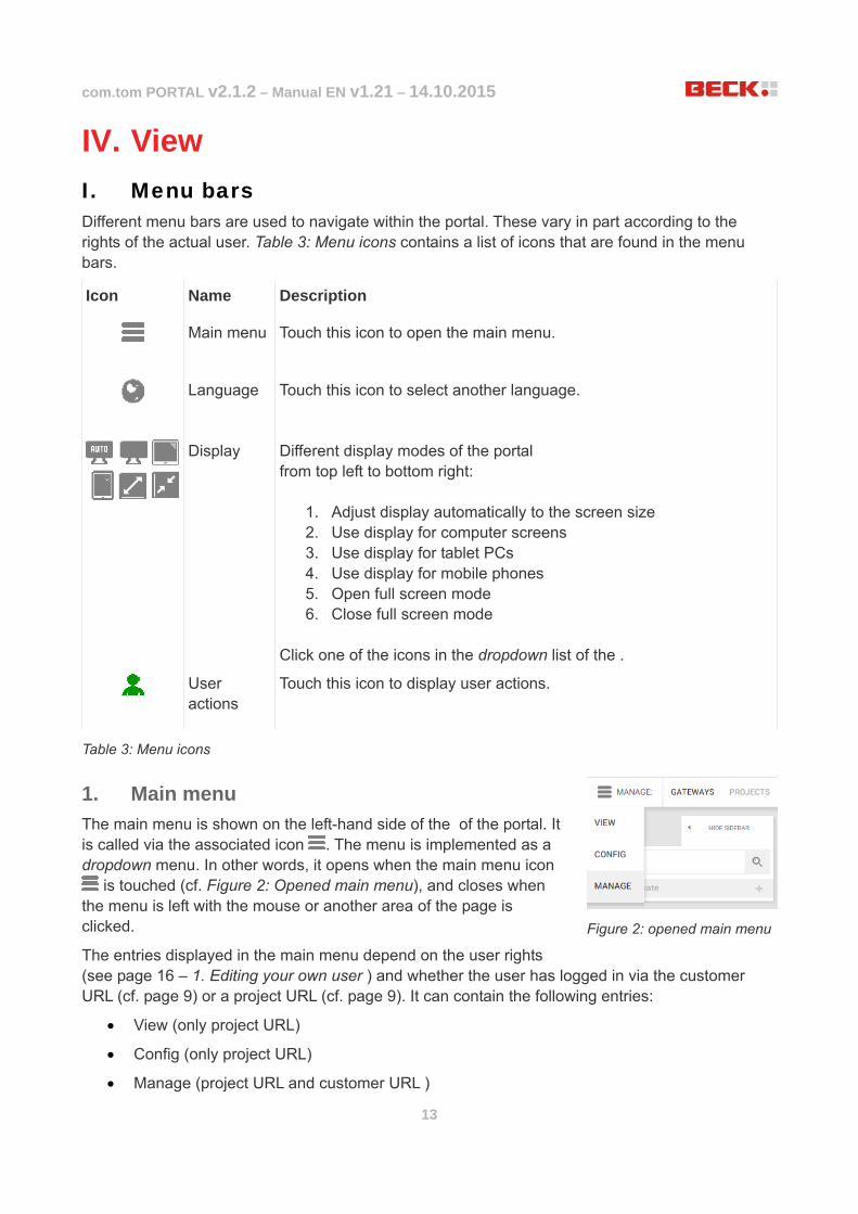
1. Main menu
The main menu is shown on the left-hand side of the of the portal. It is called via the associated icon . The menu is implemented as a dropdown menu. In other words, it opens when the main menu icon
is touched (cf. Figure 2: Opened main menu), and closes when the menu is left with the mouse or another area of the page is clicked.
The entries displayed in the main menu depend on the user rights (see page 16 – 1. Editing your own user ) and whether the user has logged in via the customer URL (cf. page 9) or a project URL (cf. page 9). It can contain the following entries:
View (only project URL)
Config (only project URL)
Manage (project URL and customer URL )
Figure 2: opened main menu

com.tom PORTAL v2.1.2 – Manual EN v1.21 – 14.10.2015
14
2. Submenu
The submenu is located on the right of the main menu icon . The entries depend on the user rights (see page 16 – 1. Editing your own user) and on the item selected.
The possible entries present are described in the subsections on the functions of the portal that can be selected on the (see page 16 – Setup). For greater simplicity, the combination of a main menu and a submenu item is illustrated in this document with the following schema:
Main menu item→Submenu item
3. Sidebar
The sidebar (see Figure 4: Sidebar) is located directly under the main menu icon and is ideal for moving between different data records. Whether it is displayed at all and the entries it contains depends both on the as well as the item selected. If required it can be shown or hidden manually. The upper section of the sidebar also contains a search field in order to search for specific data records. The list of data records is located below this. The active data record is always highlighted with the active icon . Clicking an entry activates this. This determines what is displayed in the .
The use of the sidebar is described in the subsections on the different functions of the portal which can be selected in the (see page 16 – Setup).
4. User menu
The user menu is located in the right-hand of the com.tom PORTAL. It is available at any time and without any restrictions. You can use this to change the user language (see page 11 – VII. Setting the Language and Time Zone ) or activate a different display mode. The display modes available are described on page 12 in Table 3: Menu icons. It is also possible to change personal settings via the user actions icon , cause the logout from the com.tom PORTAL or call customer and support information.
Figure 4: Sidebar
Figure 3: Submenu for the "View" main menu item"
com.tom PORTAL v2.1.2 – Manual EN v1.21 – 14.10.2015
15
II. Page areas
1. Header area
The white bar in the upper area of the com.tom PORTAL is called the header area. It contains the , and . The com.tom logo is displayed on the right-hand side. A user-defined logo can be inserted opposite on the left-hand side (see page 24 – VI. User interface).
2. Content area
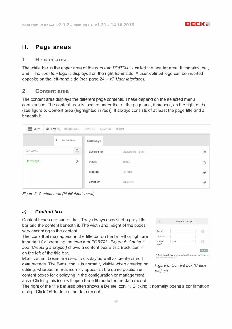
The content area displays the different page contents. These depend on the selected menu combination. The content area is located under the of the page and, if present, on the right of the (see figure 5: Content area (highlighted in red)). It always consists of at least the page title and a beneath it.
a) Content box
Content boxes are part of the . They always consist of a gray title bar and the content beneath it. The width and height of the boxes vary according to the content. The icons that may appear in the title bar on the far left or right are important for operating the com.tom PORTAL. Figure 6: Content box (Creating a project) shows a content box with a Back icon on the left of the title bar. Most content boxes are used to display as well as create or edit data records. The Back icon is normally visible when creating or editing, whereas an Edit icon y appear at the same position on content boxes for displaying in the configuration or management area. Clicking this icon will open the edit mode for the data record. The right of the title bar also often shows a Delete icon . Clicking it normally opens a confirmation dialog. Click OK to delete the data record.
Figure 5: Content area (highlighted in red)
Figure 6: Content box (Create
project)
com.tom PORTAL v2.1.2 – Manual EN v1.21 – 14.10.2015
16
V. Setup The layout of this chapter corresponds to the procedure for newly registered customers but it is also designed to be used as a reference for specific functions.
I. Editing your own user How to reach the user settings and change the time zone as well as the user language has already been described in chapter III.VII. on page 11. The user settings also allow you to change other information such as forename, surname or email address as well as your customer password. The requirements for customer passwords are described in chapter V. on page 10.
II. Creating editing and deleting other users The use of this function is limited. The following requirements must be fulfilled:
The user must be a customer administrator
It has already been explained how users can register (page 10 – 2. Registering a new user), and how the language and time zone can be edited by the administrator (page 12 – VII. - 3. As administrator). The administrator can also edit other user parameters, create new users and delete users.
For this navigate via Manage→User. The lists all the customer users. Click here on the Create user button to create a new user. A with a form opens in the . Enter user names in the left-hand column (see page 10 The user password requirements), title, forename, surname as well as a valid email address. In the middle column under Options define a preferred language and time zone, and the user password under Password (see page 10 - The user password requirements). Then set the necessary user rights (for this see 1. ) and click Save in order to create the new user.
A user is basically edited in the same way as when the user is created. Under Manage→User select the required user in the sidebar and click the Edit icon the . Carry out the required changes and confirm this by clicking Save.
In order to delete a user, first select it under Manage→User in the sidebar. Then click the Delete icon on the right-hand side inside the context box. This opens a confirmation dialog. Click OK to delete the user.
1. Managing user rights
The use of this function is limited. The following requirements must be fulfilled:
The user must be a customer administrator
The com.tom PORTAL has a complex rights system. While customer administrators have unlimited access to all areas, access for standard users has restrictions which can be largely removed by the administrator for each user.

com.tom PORTAL v2.1.2 – Manual EN v1.21 – 14.10.2015
17
Administrators can also assign administrator rights to other users and activate users for the com.tom PORTAL (for this see page 18 – Table 4: User rights under Portal). User rights are managed in the following way: Navigate via Manage→User. Select the user for whom you wish to edit the rights and click the Edit icon in the title bar of the content box or create a new user. The subsequent form shows the Rights area in the right-hand column. This contains a list with all the available rights. If a tick is set at an entry, the user already has the corresponding right. Rights can be clicked to remove or set them. The following table describes what users can do with individual rights if a tick is set:

com.tom PORTAL v2.1.2 – Manual EN v1.21 – 14.10.2015
18
Portal
Administrator The user is a customer administrator and has all available rights.
User active The user is activated and can log into the com.tom PORTAL.
Manage
Surface The user can modify the user interface.
Projects The user can create and edit projects.
Gateways The user can create, edit and delete gateways.
VPN The user can set up VPN projects.
Billing The user can view the invoices present.
Configuring
Gateways The user can add, edit and delete gateway elements.
Dashboard The user can create, edit and delete dashboards.
Map The user can add, edit and delete locations.
Graph The user can add, edit and delete dashboard graphs.
Gauges The user can add, edit and delete dashboard gauges.
Graphics The user can add, edit and delete process visualizations
Reports The user can create, edit and delete reports (regular reports for plotting values of points).
Alarm The user can create, edit and delete alarms.
Alarm user The user can create, edit and delete alarm users.
View
Gateways The user can view gateways.
Dashboard The user can view dashboards.
Map The user can see locations in a map.
Graph The user can see graphs on dashboards.
Gauges The user can see gauges on dashboards.
Graphics The user can view process visualizations.
Reports The user can view reports.
Alarm The user can view alarms.
Table 4: User rights

com.tom PORTAL v2.1.2 – Manual EN v1.21 – 14.10.2015
19
III. Creating a project The use of this function is limited. The following requirements must be fulfilled:
The user must be a customer administrator or must have Project rights of the Manage category.
The customer must have a license for setting up a project (order no. ) 40000017)
Choose Manage→Projects. Click the Create project button in the sidebar. First enter a name. The project names must fulfill the following requirements:
min. 3 characters
max. 100 characters
first character in the range a-z or A-Z or 0-9
following of an additional '-' (without quotation marks) permitted
not yet assigned
A description can be entered if required. Note that the project name also functions at the same time as the subdomain. If you wish to call up the project via the Internet browser after creating it, use the project URL with the project name as a subdomain.
A service user must also be entered. This person receives service and maintenance mails if necessary.
Clicking the Save button saves the new project. If you have successfully created a project, you can also log directly in via your new project URL.
IV. Managing gateways The use of this function is limited. The following requirements must be fulfilled:
The user must be a customer administrator or must have Gateway rights of the Manage category
The user must be logged in under a project URL.
Gateways are some of the most important elements of the com.tom PORTAL. They are used to acquire data from producers and transfer it to the server. They therefore operate as interfaces. Under Manage→Gateways it is possible to create new gateways as well as edit or delete existing ones.
1. Creating a gateway
The use of this function is limited. The following requirements must be fulfilled:
The customer must have a license for setting up a project (order no. 40000018)
Click Create gateway in the sidebar via Manage→Gateways. Select the device type and enter a name in the form (Scope). This must be unique in the project. If the required name already exists, you are notified of this when you send the form, so that you can correct it. Describe the new gateway if required and then select the used gateway device. A separate user must be created for each gateway. The right-hand column is provided for this in the form. The same conditions apply to

com.tom PORTAL v2.1.2 – Manual EN v1.21 – 14.10.2015
20
user name and password as already described on page 10 in chapter V. . The gateway name as well as the gateway user can no longer be changed at a later time. Touch Save to create the new gateway.
2. Editing a gateway
Select the gateway to be edited in the sidebar via Manage→Gateways. Click the Edit icon in the displayed content box. Make the required changes in the form and touch Save.
Note that some values cannot be changed.
3. Deleting a gateway
Select the gateway to be deleted in the sidebar via Manage→Gateways. Click the Delete icon in the displayed content box. Confirm the subsequent dialog in order to delete the gateway.
V. Configuring a gateway The use of this function is limited. The following requirements must be fulfilled:
The user must be a customer administrator or must have Gateway rights of the Configure category
The user must be logged in under a project URL.
Choose Config→Gateways. The sidebar shows a list of gateways that have already been created (color coding: green text – the gateway is online, red text – the gateway is offline, gray text – the gateway is not active, because the access data has not yet been entered on the device). The content area of the page displays a list structure of the nodes and points available. The content area of the page is displayed in a list structure. Node elements can be opened out by clicking them in order to view the subordinate elements. They can also be closed in exactly the same way. Nodes with sub elements are indicated by the highlighted arrow on the right of the list entry. If this points downwards, the subordinate elements are visible.
Points are provided as well as the nodes required for structuring. These contain values which are displayed at the same position where the highlighted arrow is located with nodes. Changes to values are displayed as quickly as possible and without the page being refreshed. A point is selected by clicking it. A value plot is displayed if available for the point.
Each node and point can be created, edited or deleted.
1. Creating an element
When a node or a point is created, it must first be determined at which location or level the element is to be created. In order to insert this on the first level, touch the Add icon on the left of the title of the content area.
In order to create an element on a lower level, it must be assigned to a node. To do this navigate to the node which is to contain the new element. All nodes have their own Add icon . Clicking this will open a form in a content box. The title of this is identical to the path that you have selected to add. First select whether you wish to create a node, a group or a point and then enter a name.The same requirements apply to the

com.tom PORTAL v2.1.2 – Manual EN v1.21 – 14.10.2015
21
name of an element as for the user name (see page 10 in the chapter V. ). If required, you can define a description.
If you are creating a node, you are already finished and can touch Save. However, if you are creating a point, you should normally carry out other settings.
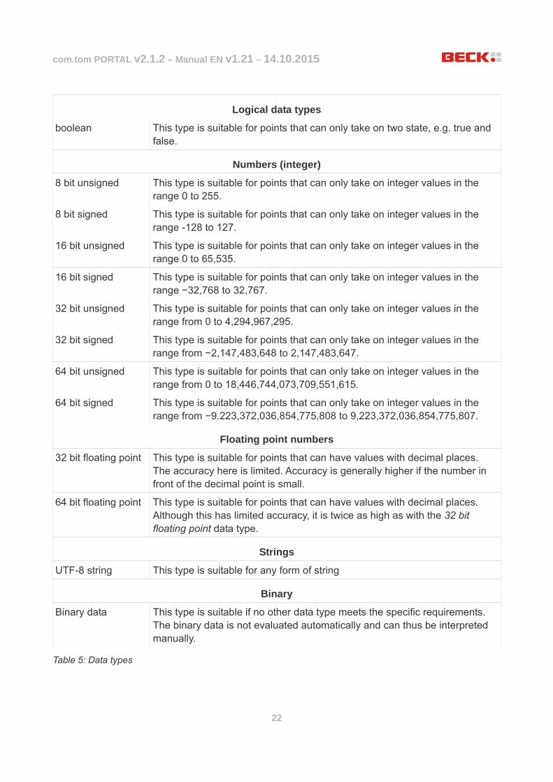
You can firstly define a data type for the value of the point. The following table explains the meaning of the listed data types and when they should be used:
com.tom PORTAL v2.1.2 – Manual EN v1.21 – 14.10.2015
22
Logical data types
boolean This type is suitable for points that can only take on two state, e.g. true and false.
Numbers (integer)
8 bit unsigned This type is suitable for points that can only take on integer values in the range 0 to 255.
8 bit signed This type is suitable for points that can only take on integer values in the range -128 to 127.
16 bit unsigned This type is suitable for points that can only take on integer values in the range 0 to 65,535.
16 bit signed This type is suitable for points that can only take on integer values in the range −32,768 to 32,767.
32 bit unsigned This type is suitable for points that can only take on integer values in the range from 0 to 4,294,967,295.
32 bit signed This type is suitable for points that can only take on integer values in the range from −2,147,483,648 to 2,147,483,647.
64 bit unsigned This type is suitable for points that can only take on integer values in the range from 0 to 18,446,744,073,709,551,615.
64 bit signed This type is suitable for points that can only take on integer values in the range from −9.223,372,036,854,775,808 to 9,223,372,036,854,775,807.
Floating point numbers
32 bit floating point This type is suitable for points that can have values with decimal places. The accuracy here is limited. Accuracy is generally higher if the number in front of the decimal point is small.
64 bit floating point This type is suitable for points that can have values with decimal places. Although this has limited accuracy, it is twice as high as with the 32 bit floating point data type.
Strings
UTF-8 string This type is suitable for any form of string
Binary
Binary data This type is suitable if no other data type meets the specific requirements. The binary data is not evaluated automatically and can thus be interpreted manually.
Table 5: Data types

com.tom PORTAL v2.1.2 – Manual EN v1.21 – 14.10.2015
23
The following flags can be set:
active: The values of the point are being transferred between the gateway and the server.
high transfer priority: The data transfer of this point is given priority
Retentive: Value is saved on the server and is written with the next gateway connection.
The point can furthermore be made writable. In other words, the value of the point can be changed manually. These changes can be restricted to a range (min. and max. fields). The value can be changed via the dashboard elements.
The Trigger Domain option makes the point into a so-called domain trigger element. When the producer sends a value, all values of points of the same domain are transferred automatically. The domain can be entered in the Domain text field. If a zero (0) is there, the point cannot be assigned to a domain. Other points are only “triggered” if you have the Trigger Domain (5) mode or if they are themselves domain trigger elements.
The trigger mode determines in which case values of the points are to be transferred. The following table explains the possibilities:
Any change (0) Any status change is transferred.
Only from the producer (1)
Only status changes of the producer are transferred.
Trigger value (2) Status changes are only transferred if the new value has at least a specific difference to the previous value. This difference is defined in the Value field.
Trigger Sec (3) The status is transferred after the number of seconds specified in the Sec field, regardless of whether the status has changed or not.
Trigger value+Sec (4) Combination of (2) and (3). The status is only transferred after the number of seconds specified in the Sec field if the difference between the old and new value is at least the difference stated in the Value field.
Trigger domain (5) The status is always transferred if at least one domain trigger element of the same domain transfers its status.
Trigger Sec+Valid (6) The status is only transferred after the number of seconds specified in the Sec field if the value or quality has changed in comparison to the previously received status.
Table 6: Trigger modes

com.tom PORTAL v2.1.2 – Manual EN v1.21 – 14.10.2015
24
A transfer schema (QoS) can also be defined. The following schemas are available:
Max. once (0) One-time transfer of the value. The recipient does not confirm the receipt of the data.
Min. once (1) The value is transferred until the recipient confirms receipt of the data. If a new value is available, the transfer of the previous value is aborted.
Min. once+new (2) Like (1), but if a newer value is available, the transfer is not carried out until the previous value was transferred successfully.
Exactly once (3) Each value is transferred exactly once.
Exactly once+new (4) Like (3), but if a newer value is available, the transfer is not carried out until the previous value was transferred successfully.
Table 7: Transfer schemas
The Plot option defines the number of days for which the status plot of the point is to be saved. If the value is higher than the maximum status plot backup period for the project, it is reduced to this value. The value 0 deactivates the backup of the plot. Changes only have an effect on future plots.
A format template for the display of the value can be defined in the Format field.
The Scale setting defines how the values of the point are scaled before they are presented to the consumer. The scaled value is calculated as follows: value * factor + offset
Lastly, you can define an Update URL, i.e. an Internet address which is called if the status of the point changes.
Clicking Save creates the element, assigns it to the selected node and displays it in the overview.
2. Editing elements
Choose Config→Gateways and select in the sidebar the gateway for which you wish to edit the element. Find the element in the list in the content area and click its Edit icon on the right of the entry. The editing page for the element will open. For nodes it is only possible to change the description, whereas points offer considerably more setting options. Read page 20 – 1. from the fourth paragraph onwards for more detailed information on the individual settings. Click Save to save the changes.
3. Deleting an element
Choose Config→Gateways and select in the sidebar the gateway for which you wish to delete the element. Find the element in the list in the content area and click on its Delete icon on the right of the entry. This opens a confirmation dialog. Clicking OK deletes the element.

com.tom PORTAL v2.1.2 – Manual EN v1.21 – 14.10.2015
25
VI. User interface The use of this function is limited. The following requirements must be fulfilled:
The user must be a customer administrator or must have Surface rights of the Manage category.
Choose Manage→Interface. On this page you can adjust the user interface of the com.tom PORTAL to your requirements. Changes apply to all customers. Choose any background color or an individual background image with the following requirements:
File suffix .jpg or .png
min. 100 pixels (e.g. 10 x 10 pixels)
max. 3.2 mega pixels (e.g. 1920 x 1080 pixels or 2048 x 1536 pixels)
It is also possible to upload a logo, which is displayed on the left-hand header area of the page. The same requirements apply here as for the background image. The logo is displayed in the top left header area and can adjust itself to different screen and window sizes. Different logo variants can be uploaded for this purpose. This therefore enables a large logo to be shown with a wide display. If the display is narrow, a smaller logo is used. Bear in mind, however, that images that are too large have to be scaled down so that they fit into the header area. Use the different pixel settings next to the file upload fields in order to achieve an optimum result.
Changes are applied when the Save button is clicked. Use the tooltip system to obtain important information.
com.tom PORTAL v2.1.2 – Manual EN v1.21 – 14.10.2015
26
VI. Other functions
I. Managing projects The use of this function is limited. The following requirements must be fulfilled:
The user must be a customer administrator or must have Project rights of the Manage category.
A list of your customer projects is found at Manage→Projects in the . This provides you with different management options.
1. Creating a project
For creating projects, see page 19: III.Creating a project.
2. Editing a project
Select the project to be edited in the sidebar via Manage→Projects. Click the Edit icon in the displayed content box. Make the required changes in the form and touch Save.
Note that some values cannot be changed.
3. Deleting a project
The delete function is not available for projects. Contact the Beck customer service if you wish to delete a project.
II. Billing The use of this function is limited. The following requirements must be fulfilled:
The user must be a customer administrator or must have Billing rights of the Manage category.
The page accessed via Manage→Billing shows the monthly costs divided up according to the different projects. The current month is always displayed automatically. The invoicing for the previous months can be called via the selection box on the right next to the page title. The page does not offer any other interactive elements but is useful for keeping the costs for the previous months in view.
III. Dashboards The use of this function is limited. The following requirements must be fulfilled:
View: The user must be a customer administrator or must have Dashboard rights of the View category.
Configuration: The user must be a customer administrator or must have Dashboard rights of the Config category.
The user must be logged in under a project URL.
Dashboards are used to visualize data provided via gateways. This visualization is provided in the

com.tom PORTAL v2.1.2 – Manual EN v1.21 – 14.10.2015
27
content area via content boxes that can be added, changed or removed as required. Choose View→Dashboard in order to view existing dashboards or Config→Dashboard to create new dashboards, edit or delete existing ones, or to add elements to dashboards or edit or delete existing ones. Bear in mind that some dashboard elements are also subject to rights. These include maps, graphs and gauges (see also page 16 – 1. ).
The arrangement of the dashboards in the sidebar can be changed by drag and drop (indicated by the Move icons ).
1. Creating a dashboard
Click Create dashboard in the sidebar via Config →Dashboard. This opens a form. Assign a new dashboard a name and a descriptive text, if required, and click Save in order to create it. Your dashboard will then appear in the sidebar.
2. Editing a dashboard
Choose Config→Dashboard to select the dashboard to be edited. The page title of the content area contains three buttons. Click the Edit icon . This opens a form. Make the required changes and touch Save.
3. Deleting a dashboard
Choose Config→Dashboard to select the dashboard to be edited. The page title of the content area contains three buttons. Click the Delete icon and confirm the dialog that appears by clicking OK in order to delete the selected dashboard.
4. Dashboard elements
Different display formats are available for the optimum visualization of different data. You can create, edit and delete new elements under Config→Dashboard. To create an element choose in the sidebar the dashboard to which you wish to add an element and click on the Add icon to the left of the content area title. Assign a name to the element and define how many columns it is to have. Lastly define a type. The following table shows the types and their suitability:
Table Simple display of points in a table
Gauge Display a single value on a “Speedometer”. Different ranges can be defined.
Tank Level display in a vertical bar
Google Maps Select places (e.g. location of devices) on a map
Graph Display of value plot of one or several points
Table 8: Dashboard elements
Click Save to create the element and cause it to appear on the dashboard. The entered name is displayed here as a title. It is still empty at first and should therefore be edited afterwards. Click the Edit icon on the left of the title bar in order to start editing. The element then switches to editing

com.tom PORTAL v2.1.2 – Manual EN v1.21 – 14.10.2015
28
mode. This can be closed via the Back icon , which is displayed instead of the Edit icon. No changes will be saved by this step. In order to apply the changes, click instead in Edit mode on the tick on the right-hand side of the title bar. The name (Title field) and the required number of columns (Columns field) can be redefined for each element.
a) Editing a table
Activate the Edit mode of the table. Three buttons are provided in the lower area for adding table rows. Clicking one of the buttons adds a configuration area for the new row in the form. A designation must be entered in the Name field for each added row. The Path field is used to define step by step a path to a point for which the value is to be displayed in the table. All other parameters depend on the row type.
Text
◦ No other parameters
Button
◦ Image: Select an image that is placed on the button 1*
◦ Text: Button text
◦ Value: The value entered here is written by clicking the button. 2*
◦ Math: Mathematical formula for converting the value. The result is written by clicking the button. The following placeholders can be used:
▪ [this] → This placeholder is replaced by the actual value of the point. If, for example, you write "[this] + 1", every click on the button will increase the value by 1.
▪ [realValue] → This placeholder is replaced by the actual value of the point, taking the scaling factor into account (see page 24).
◦ Bit: If this option is set, the button refers only to the bit defined here for the value of the selected point.
Button True-False
◦ True Image: Select an image that is placed on the button if it is active (i.e. the reference point defined in the Path field has the value "true".)
◦ False Image: Select an image that is placed on the button if it is inactive (i.e. the reference point defined in the Path field has the value "false".)
◦ Action: If this field is activated, clicking this button inverts the value of the reference point ("true" becomes "false", "false" becomes "true"). Otherwise the button is only used for display purposes.
◦ Bit: If this option is set, the button refers only to the bit defined here for the value of the selected point. The True-False button can be used in this way for bitwise value changes.
Created lines can be deleted at any time in Edit mode via the red Delete button. 1* The Text field is ignored if an image is selected. 2* The Value field is ignored if a formula is entered in the Math field for calculating a new value.

com.tom PORTAL v2.1.2 – Manual EN v1.21 – 14.10.2015
29
b) Editing a gauge
Activate the Edit mode of the gauge. In the Min field define the position of the zero point. The Max field is used to define the maximum permissible value. The Unit field also enables you to enter the unit for the value of the point (for display purposes). The lower area contains an Add icon . Clicking it creates a new range, which is shown in color in display mode. Define a range (From and To) and a color. Ranges can be deleted at any time via the red Delete button in Edit mode.
c) Editing a tank
Activate the Edit mode of the tank. In the Min field define the position of the zero point. The Max field is used to define the maximum permissible value. The Unit field enables you to also enter the unit for the value of the point. The lower area contains an Add icon . Clicking it creates a new range, which is shown in color in display mode. Define a range (From and To) and a color. Ranges can be deleted at any time via the red Delete button in Edit mode.
d) Editing Google Maps
Note: Google Maps operates with longitude and latitude information. In order to configure the map correctly, the longitude and latitude information of the location to be selected must be available as a floating point number or by automatically calling it from a gateway. Activate the Edit mode of the map. Define the center of the map (form: longitude, latitude). and a Zoom level in the range from 0-18 (the higher, the closer). The lower area contains an Add icon . Clicking it creates a new marker on the map. You can assign this a name. A URL description can be entered in the Link field. Clicking on the marker in the display activates the entered website. In the State field select a gateway to which the marker is to refer. Its color then automatically adjusts itself to the status of the gateway (green for online, red for offline, gray for inactive). The Lat and Long fields are used to enter the target coordinates of the marker (latitude and longitude). These can be entered manually in the text fields. Alternatively, paths to points can be entered which contain the geocordinates as values.
e) Editing graphs
Activate the Edit mode of the graph. First enter in the Period (past) field the range visible in the graph.
From/To: A precisely defined period (start and end) is shown in the graph. If this point is selected, a start and end time must be entered in the From/To field.
Past: The time just past for a defined period is shown in the graph. If this point is selected, a period (integer) and an interval (seconds, minutes, hours or days) must be entered in the following Past field.
You can define in the Auto refresh field an interval (seconds, minutes, hours or days) in which the graph is to be refreshed in the display.

com.tom PORTAL v2.1.2 – Manual EN v1.21 – 14.10.2015
30
The lower area contains an Add icon . Clicking it can define a new reference point for which the value plot is to be displayed in the graph. Enter for this a name and a line color. Also select the point for which the value plot is to be displayed. In Y Min/Max it is possible enter the minimum and maximum value for the Y axis. If these fields are empty, minimum and maximum are determined automatically. A unit can also be defined in the Unit field for the display of the Y axis. If the Step? field is activated, the line is not displayed as a smooth plot but with clear steps at value changes.
f) Deleting an element
Find the element to be deleted on the dashboard and click on its Delete icon on the right of the title bar. Confirm the subsequent dialog in order to delete the element.
IV. Alarm The use of this function is limited. The following requirements must be fulfilled:
View: The user must be a customer administrator or must have Alarm rights of the View category.
Configuration: The user must be a customer administrator or must have Alarm rights of the Config category.
The user must be logged in under a project URL.
Alarms can indicate critical changes of values for different points and thus enable a fast reaction. An alarm always has at least one condition that must be fulfilled so that it is triggered. An alarm also always has one alarm user. This is basically a collection of alarm recipients which are notified in the event of an alarm for which their time availability can be defined (see for this page 33 – V.).
Choose the View→Alarm page to view all created alarms of the customer in a list with their details. Here you can also acknowledge unacknowledged alarms if present
1. Creating or editing an alarm
In order to create or edit a new alarm choose Config→Alarm. Click in the sidebar on Create alarm to create a new alarm or choose in the sidebar an alarm to be edited and click the Edit icon in the left content box in order to edit an alarm. This opens a form.
Assign a name to the alarm in the Name field. Bear in mind that you cannot create several alarms under the same name for one customer.
If required enter a description and select an alarm user.
Define an alarm interval and a trigger mode:
Acknowledge only: An alarm can only be triggered if the last alarm of the same type was acknowledged.
Always: The alarm is always triggered irrespective of whether there is an unacknowledged alarm of the same type.
If required select an SMS tariff. SMS sent via the com.tom PORTAL are charged and are shown at Manage→Billing. The following tariffs are possible:

com.tom PORTAL v2.1.2 – Manual EN v1.21 – 14.10.2015
31
SMS Germany Sending only with Germany
SMS International Sending worldwide, expensive
- No SMS sending on alarm
Table 9: SMS tariffs
2. Deleting an alarm
Choose Config→Alarm and select in the sidebar the alarm which you wish to delete. Click the Delete icon in the left-hand content box. This opens a confirmation dialog. Click OK to delete the alarm.
3. Alarm conditions
At least one condition must be fulfilled in order for an alarm to trigger. Conditions refer to the values of points. All conditions set for an alarm are listed in content area in the right-hand context box with the title Alarm conditions.
a) Adding an alarm condition
Choose Config→Alarm and select in the sidebar the alarm for which you wish to add a condition. Click the Add icon in the right-hand context box with the Alarm conditions title in order to create a new alarm condition. You can now choose whether the condition is to refer to the value of a gateway element (node) or a user action (user).
a) Node alarm condition
First select step by step the path to the point to be controlled. Then select a control operator. The following operators can be used:
“==” The value of the point equals the stated control value.
“!=” The value of the point does not equal the stated control value.
“>” The value of the point is greater than the stated control value.
“>=” The value of the point equals or is greater than the stated control value.
“<” The value of the point is less than the stated control value.
“<=” The value of the point equals or is less than the stated control value.
Table 10: Operators
Lastly enter a control value which is compared with the value of the point using the control operator and click Save in order to create a new alarm condition. The condition is then listed in the previously described content box.
com.tom PORTAL v2.1.2 – Manual EN v1.21 – 14.10.2015
32
b) User alarm condition
First of all select a user. You can then set ticks with any number of actions. The alarm is triggered if one of the selected actions occurs. The following actions are available:
login The alarm is triggered if the user logs into the com.tom PORTAL.
close The user logs out of the com.tom PORTAL .
timeout The connection between user and the com.tom PORTAL is closed.
emergencies There is a critical connection problem.
Table 11: User actions
Click Save to create a new alarm condition. The condition is then listed in the previously described content box.
b) Editing an alarm condition
Choose Config→Alarm and select in the sidebar the alarm with the condition you wish to edit. Find in the right-hand content box the condition to be edited and click the Edit icon of the relevant list entry. This opens a form, for which the view depends on whether the condition is controlled by a node or a user action. Carry out the required changes and confirm this by clicking Save.
c) Deleting an alarm condition
Choose Config→Alarm and select in the sidebar the alarm for which you wish to delete the condition. In the Alarm conditions content box find the condition you wish to delete. Click the Delete icon on the right-hand side of the list entry. Click OK in the confirmation dialog to delete the condition.

com.tom PORTAL v2.1.2 – Manual EN v1.21 – 14.10.2015
33
V. Alarm user The use of this function is limited. The following requirements must be fulfilled:
The user must be a customer administrator or must have Alarm rights of the Config category.
The user must be logged in under a project URL.
Alarm users control the sending of alarms. Choose Config→Alarm User to specify the people to be notified when an alarm is triggered.
1. Creating an alarm user
Choose Config→Alarm User and click the Alarm user button in the sidebar. This opens a form.
Assign a name to the alarm user in the Name field. Bear in mind that you cannot create several alarm users under the same name for one customer.
Define a first alarm recipient by entering a name, email address and, if necessary, a phone number for receiving SMS messages and click Save in order to save a new Alarm user.
Bear in mind that the alarm recipient created here has a special status. The person cannot be deleted and cannot be assigned a time range (he/she is always available) in order to prevent any gaps in the alarm plan.
2. Editing an alarm user
Choose Config→Alarm User to select in the sidebar the alarm user to be edited and click the Edit icon in the left-hand content box. This opens a form. You can only change the name here. Bear in mind that you cannot create several alarm users under the same name for one customer. Confirm your changes by clicking the Save button.
3. Deleting an alarm user
Choose Config→Alarm User and click in the sidebar the Alarm user to be deleted. Click the Delete icon in the top left content box. This opens a confirmation dialog. Clicking OK deletes the alarm user.
4. Alarm recipient
Alarm recipients are contacts who are notified in the event of an alarm being triggered. It is possible to include here the times in which a particular person can be reached. All recipients set for an alarm are listed in the content area on the right-hand side in the box with the title Alarm recipients. Bear in mind that the order of the recipients is important for time overlaps. In this case the entry that is positioned higher is always used as the alarm recipient for overlapping period. If there are more than two alarm recipients, the entries can be re-arranged with drag and drop (indicated by the Move icon ).
a) Adding an alarm recipient
Choose Config→Alarm User to select in the sidebar the alarm user to whom you wish to add a
com.tom PORTAL v2.1.2 – Manual EN v1.21 – 14.10.2015
34
recipient. Click the Add button in the content box with the title Alarm recipient. This opens a form. Enter a name, email address and, if necessary, a phone number for receiving SMS messages as well sa the time in which the recipient is available and click Save in order to save the new Alarm user. This person is then listed in the previously described content box.
b) Editing an alarm recipient
Choose Config→Alarm User and select in the sidebar the alarm user for whom you wish to edit the alarm recipient. In the Alarm recipient content box find the recipient you wish to edit. Bear in mind that restrictions apply to the first alarm recipient created (simultaneously with the alarm user) when editing (see page 33 – 1. Creating an alarm user ). Click the Edit icon on the right-hand side of the list entry. This opens a form. Make the required changes in the form and touch Save.
c) Deleting an alarm recipient
Choose Config→Alarm User and select in the sidebar the alarm user for which you wish to delete the alarm recipient. In the Alarm recipient box find the recipient you wish to delete. Click the Delete icon on the right-hand side of the list entry. This opens a confirmation dialog. Clicking OK deletes the element.
5. Alarm plan
The alarm plan of an alarm is automatically calculated from the stated alarm recipients. This shows which recipient is assigned for receiving alarm messages at a particular time. The calculation uses the order of the entered alarm recipients when there are overlaps. If two or several recipients are therefore assigned to the same time, the recipient positioned uppermost in the list is always assigned to this period.
VI. Reports The use of this function is limited. The following requirements must be fulfilled:
The user must be a customer administrator or must have Reports rights of the Config category.
The user must be logged in under a project URL.
Reports make it possible to collate and evaluate the gateway data acquired over a long period.
1. Creating a report
Choose Config→Reports and click the Create report button in the sidebar. This opens a form.
Assign a name to the report in the Name field. A time zone must be set for each report, to which the date and time information of the report is adjusted. If required enter a description which is shown in the sidebar underneath the name. The Period selection field sets the period in which data is collated in the report. The Compression selection field on the other hand determines the interval between the individual data items. The subsequent language selection primarily refers to the emails sent. Email addresses to which the report is sent as a CSV file can be entered for this. When there are several recipients, enter each email address in a separate line.

com.tom PORTAL v2.1.2 – Manual EN v1.21 – 14.10.2015
35
In the right-hand area of the form enter an interval in which the report is to be created and sent. Multiple
selections are possible in all fields (time, weekday, day and month).
In order to select an entire range, click the starting point, hold down the Shift key and move to the required end point. If you wish to add or remove individual elements, click them whilst pressing the Ctrl key. The interval fields are combined with each other. For example, if you wish to receive a report at 8:00 a.m. on the first Monday of each month, select “08:00” in the Time field, “Mo.” in the Weekday field, the range “01”-“07” in the Day field and everything in the Month field.
Lastly, click Save to create the report.
2. Editing a report
Choose Config→Reports to select in the sidebar the report to be edited. Then click the Edit icon in the left-hand content box. This opens a form. Carry out the required changes and confirm this by clicking Save.
3. Deleting a report
Choose Config→Reports to select in the sidebar the report to be deleted. Click the Delete icon in the left-hand content box. This opens a confirmation dialog. Clicking OK deletes the report.
4. Report Nodes
In order for a report to contain data, it must be assigned at least one gateway element, the values of which are to be written to the report. The “Report Nodes” content box on the right-hand side of the content area under Config→Reports is used for this. This lists all the elements already linked.
a) Creating a report node
Choose Config→Reports and select in the sidebar the report for which you wish to create a new point. Click the Add icon in the right-hand content box. In the form that appears first choose step by step the path to the point with the value that must be listed in the report. Then define a period for which the values are to be recorded. Also enter a name for the point if required.
b) Editing a report node
Choose Config→Reports and select in the sidebar the report with the node you wish to edit. In the Report nodes content box find the entry you wish to edit. Click the Edit icon on the right-hand side of the list entry. This opens a form. Make the required changes in the form and touch Save.
c) Deleting a report node
Choose Config→Reports and select in the sidebar the report with the node you wish to delete. In the Report nodes box find the entry you wish to delete. Click the Delete icon on the right-hand side of the list entry. This opens a confirmation dialog. Clicking OK deletes the entry.
5. Displaying and downloading reports
The use of this function is limited. The following requirements must be fulfilled:
com.tom PORTAL v2.1.2 – Manual EN v1.21 – 14.10.2015
36
The user must be a customer administrator or must have Reports rights of the View category.
The user must be logged in under a project URL.
Choose View →Reports. Choose from the sidebar the report you wish to display. The content area will then show a list of the created reports. The newest report is at the top. On the right of each list entry is a Download button for downloading the report as a CSV document.
com.tom PORTAL v2.1.2 – Manual EN v1.21 – 14.10.2015
37
VII. Map The positions of gateways can be called up and displayed via View→Map. This requires the gateways to be configured beforehand.
1. Displaying a map
The use of this function is limited. The following requirements must be fulfilled:
The user must be a customer administrator or must have Map rights of the View category.
The user must be logged in under a project URL.
Choose View→Map. If the map was already configured, it is displayed via the complete screen. It shows markers that indicate the location of the gateways. Placing the mouse over the markers will display the name of the particular gateway. Clicking on it will open an information window with additional information about the gateway. The color of the marker indicates the status of the gateway (green for online, red for offline, gray for inactive). If a yellow warning symbol is also displayed in the center of the marker, this means that an alarm condition has been fulfilled on the gateway.
Clicking on the arrow left of the page title will open the sidebar. This displays all the gateways configured for the map. Clicking on one of them will focus on it to open its information window.
2. Configuring a map
The use of this function is limited. The following requirements must be fulfilled:
The user must be a customer administrator or must have Map rights of the Configure category.
The user must be logged in under a project URL.
Choose Config→Map. The sidebar displays all the gateways. Choose a gateway to configure for the display on the map.
Clicking the Edit icon on the left of the title of the content box opens a form.
The type determines whether the gateway has a fixed location or whether it changes location. Choose “static” for a fixed location and enter the latitude and longitude as a floating point number in the corresponding text input fields. The fields below it stay empty.
Choose “dynamic” for a gateway with a variable location. In this case, gateway variables with location information must be selected in the bottom two fields. In the Latitude field select a variable with latitude information as a floating point number and another variable with longitude information in the Longitude field (also a floating point number).
Accept the changes by clicking the Save button. Configured gateways are displayed on the map via View→Map.


