UNIVERSIDAD REY JUAN CARLOS INGENIER ´ IA T ´ ECNICA EN INFORM ´ ATICA DE SISTEMAS Curso Acad´ emico 2003/2004 Proyecto fin de carrera Dise˜ no e Implementaci´ on de controladores Hardware y Software para comunicaciones inal´ ambricas Bluetooth basado en el chip ROK 101/007 de Ericsson y el Microcontrolador AT89C2051 de Atmel AUTOR: Gregorio Zamora Merino TUTOR: Juan Antonio Hern´ andez Tamames FEBRERO 2004
Transcript
UNIVERSIDAD REY JUAN CARLOS
INGENIERIA TECNICA EN INFORMATICA DESISTEMAS
Curso Academico 2003/2004
Proyecto fin de carrera
Diseno e Implementacion de controladoresHardware y Software para comunicaciones
inalambricas Bluetooth basado en el chip ROK101/007 de Ericsson y el Microcontrolador
AT89C2051 de Atmel
AUTOR: Gregorio Zamora Merino
TUTOR: Juan Antonio Hernandez Tamames
FEBRERO 2004
Resumen
En este proyecto se busca obtener una plataforma hardware multipropositocon capacidades de comunicacion inalambricas. Para ello se ha seleccionadoel microcontrolador 8051, de amplia difusion y muy bajo coste, y el sistemade comunicacion Bluetooth.
Con este proyecto se intenta adquirir el conocimiento necesario para eldesarrollo de aplicaciones con Bluetooth: para que sirve, que se puede hacery, sobre todo, como hacerlo.
En particular, se ha desarrollado un protocolo de comunicacion serie,basado en la torre de protocolo de Bluetooth pero no en su totalidad. Se haimplementado el mınimo imprescindible para lograr una comunicacion, con elfin de que no resulte gravosa su implantacion en equipos como el 8051 dondela memoria utilizada es limitada en el desarrollo de este tipo de aplicaciones.
3.1.1. Un ordenador con capacidades Bluetooth . . . . . . . . 143.1.2. Una tarjeta hija de Bluetooth . . . . . . . . . . . . . . 143.1.3. Un 8051 . . . . . . . . . . . . . . . . . . . . . . . . . . 14
3.2. Especificacion . . . . . . . . . . . . . . . . . . . . . . . . . . . 153.2.1. Lado Cliente o lado del PC . . . . . . . . . . . . . . . 183.2.2. Lado Servidor o lado del 8051 . . . . . . . . . . . . . . 22
4. Conclusiones. 31
5. Bibliografıa 32
6. Apendices 33
ii
1. Introduccion.
1.1. ¿Que es Bluetooth?
El concepto de Bluetooth surge de la imperiosa necesidad de las grandesempresas de telecomunicaciones e informatica, de desarrollar una interfazabierta, que facilite la comunicacion entre los diferentes equipos informaticosy telefonicos, aprovechando la capacidad y la movilidad de los dispositivosinalambricos, para la total supresion de los cables de conexion, adoptandoası un unico estandar de conexion. Bluetooth se puede definir como una prop-uesta de especificacion de radio frecuencia por transmision de corto alcancede datos, pudiendo transmitir a traves de objetos solidos no metalicos. Sualcance nominal es de 10 cm a 10 m en teorıa, pero puede extenderse a 100m mediante el incremento de transmision de energıa.
Los ordenadores, telefonos moviles, aparatos domesticos y equipos de ofic-ina, basados en Bluetooth pueden conectarse entre sı dentro de areas fısicasreducidas, sin necesidad de utilizar cableado, de forma segura y barata y aaltas velocidades de transmision. Tambien se pretende ofrecer acceso a In-ternet, a traves de LAN y dar soporte para la sincronizacion de datos entredispositivos informaticos. Una gran ventaja es que en la lınea de comuni-cacion pueden existir obstaculos materiales.
Las tarjetas Bluetooth son pequenos dispositivos radio de baja potencia,sobre un chip que se comunican con otros productos basados en el estandar.Ası, podemos eliminar los cables a la hora de conectar dispositivos comoordenadores portatiles, PDAs, telefonos moviles, impresoras o maquinas defax, entre otros equipos. La conexion se puede realizar tanto punto a puntocomo punto-multipunto. Al soportar comunicaciones de voz y datos, Blue-tooth puede ser extendido a comunicaciones ”manos libres” para telefonosinalambricos en vehıculos. La tecnologıa usa la banda ISM (Industrial Scien-tific Medicine) de los 2.4 GHz que no necesita licencia, esta disponible en casitodo el mundo, aunque debe adaptarse a las interferencias de los pequenosmonitores, mandos de garaje, telefonos sin cables, microondas, que tambienusan esta frecuencia.
Bluetooth es ademas, un modulo radio de baja potencia, puede integrarseen una amplia variedad de dispositivos. Soporta transmision de tres canalesde voz, vıdeo y datos a una velocidad maxima de 1 Mbps, aunque la maximavelocidad real girara alrededor de los 721 Kbps.
El estandar ha sido disenado para operar en un entorno multiusuario. Dehecho, permite conectar hasta ocho usuarios, o dispositivos situados dentro deuna pequena red llamada picorred. Diez de estas picorredes pueden coexistir
1
en un mismo espacio de cobertura de radio. Para proporcionar seguridad,cada enlace es codificado y protegido contra interferencias e intrusiones.
Para los administradores de redes, las microrredes Bluetooth ofrecen muchasventajas pero comportan algunos retos. Es cierto, que en una picorred sepueden ofrecer servicios sin requerimientos de seguridad, (las impresorasbasadas en Bluetooth de una sala de reuniones, por ejemplo, podrıan serutilizadas sin necesidad de configurarlas), pero tambien lo es, sin embargo,que si la empresa tiene instalada LAN inalambricas (IEEE 802.11b) am-bas tecnologıas pueden interferir entre sı. Para minimizar este problema, losadministradores de redes deben situar convenientemente las picorredes Blue-tooth y las LAN inalambricas.
1.2. Especificaciones generales de la tecnologıa Blue-tooth
En la siguiente tabla, se muestran de forma generica las especificaciones dela tecnologıa Bluetooth. Algunos elementos, como por ejemplo, las ”piconets”(picorredes) seran desarrollados con mas detalle en el estudio posterior.
2
EspecificacionesBanda de frecuencia 2.4 GHzPotencia del transmisor 1 mW (0 dBm)Tecnologıa RF Espectro Ensanchado por Secuencia
Directa Hıbrida y Saltos en frecuencia(FH-SS)
Velocidad de datos 721 Kbps por piconetRango esperado del sistema 10 metros. Extension a 100 metrosNo maximo de dispositivos 8 por piconet. 10 piconets en un area
de cobertura 1(scatternet)No maximo canales de voz 3 por piconetNo maximo canales de datos 7 por piconetSeguridad Sı, en la capa de enlaceAlimentacion 2.7 VoltiosConsumo de potencia:Sleep 30 microamperiosHold 60 microamperiosStandby 300 microamperiosTransmitiendo 8 - 30 mATamano del modulo 0.5 pulgadas cuadradas (327.68 mm 2 )Interferencias Bluetooth minimiza la interferencia po-
tencial al emplear saltos rapidos en fre-cuencia de 1600 veces por segundo.
Cuadro 1: Especificaciones generales Bluetooth
3
1.3. Torre de protocolos.
La especificacion de Bluetooth pretende que todas las aplicaciones quesigan esta sean capaces de operar entre sı. Para conseguir esta interoperabili-dad, las aplicaciones en dispositivos remotos deben ejecutarse sobre una pilade protocolos identicos. A continuacion se muestra la pila de protocolos tal
y como aparece descrita en la especificacion:
Figura 1: Pila de protocolos Bluetooth.
No todas las aplicaciones hacen uso de todos los protocolos que confor-man la pila, y algunas aplicaciones se ejecutan sobre una o mas columnasde la torre. La pila completa se compone tanto de protocolos especıficos deBluetooth (LMP y L2CAP, por ejemplo) como de protocolos no especıfi-cos de Bluetooth como son OBEX (Objects Exchange Protocol), UDP (Us-er Datagram Protocol), TCP, IP, etc. Debido a que la hora de disenar latorre de protocolos, el objetivo principal ha sido maximizar el numero deprotocolos existentes que se puedan reutilizar en las capas mas altas paradiferentes propositos. La reutilizacion de protocolos es muy importante, parapoder hacer que diferentes aplicaciones comerciales ya existentes, utilicen es-tos protocolos, y puedan interoperar con Bluetooth. Ademas, la especificacionesta abierta a implementaciones libres (propietarias), o nuevos protocolos deaplicacion de uso comun. Ası, se pretende que se puedan desarrollar un grannumero de aplicaciones, que gocen de las ventajas de la tecnologıa Bluetooth.
4
La torre de protocolos se puede dividir en cuatro capas logicas, de acuerdoa su proposito. La division es la siguiente:
Capa de protocolo Protocolos de la pilaNucleo de Bluetooth BaseBand, LMP, L2CAP,
SDPSustitucion del cable RFCOMMControl de Telefonıa TCS Binary, AT-CommandsProtocolos adoptados PPP, UDP/TCP/IP,
OBEX, WAP, VCard,VCal, IRMC, WAE
Cuadro 2: Clasificacion protocolos Bluetooth.
A parte de todos estos protocolos, la especificacion define el HCI (HostController Interface), que se encarga de proporcionar una interfaz de coman-dos al controlador BaseBand, al gestor de enlace, y nos da acceso al estadodel hardware y a los registros de control. En la figura de la torre de protocolosaparece, colocado por debajo de L2CAP, pero esta posicion no es obligatoria,ya que, HCI puede estar tambien por encima de L2CAP.
Los protocolos denominados ”nucleo de Bluetooth”, son aquellos desarrol-lados especıficamente para Bluetooth. Los protocolos ”nucleo de Bluetooth”(mas Bluetooth radio logicamente), deben ser implementados por practica-mente la mayorıa de dispositivos Bluetooth, mientras que el uso de los demasprotocolos esta supeditado a los casos en que estos sean necesarios.
Por su parte, las capas logicas de sustitucion de cable, de control detelefonıa y de protocolos adoptados, agrupan a los protocolos orientados aaplicacion, permitiendo ası a las diferentes aplicaciones existentes o desar-rolladas en el futuro poder correr sobre el nucleo de Bluetooth. Como ya semenciono antes, la especificacion es abierta en cuanto a los protocolos quecorren encima de los protocolos especıficos de transporte, y ası se puedenhacer implementaciones que usen protocolos tan usados como HTTP, FTP,y un largo etcetera.
A partir de aquı, vamos a realizar una descripcion de todos los protocolosque emplea Bluetooth, centrandonos un poco mas en aquellos protocolosespecıficos de Bluetooth y que constituyen la base de su funcionamiento.
5
1.4. Entorno de desarrollo.
El material que hemos utilizado, se ha comprado a la companıa llamadaIAR Systems, la cual, es uno de los principales proveedores del mundo enherramientas de desarrollo y de servicios para sistemas embebidos, que seutilizan para productos que contienen microprocesadores, como por ejemplo:telefonos moviles, sistemas del GPS, unidades de mando a distancia y juegospara computadora.
Ademas, esta companıa se dedica al desarrollo de software, para susclientes. IAR Systems igualmente desarrolla y comercializa una gran gamade productos y servicios, para que puedan ser usados en el diseno, desarrolloy pruebas de sistemas.
Entre los muchos productos que ofrece dicha empresa, nosotros hemoselegido el Starter kit Bluetooth. Este kit se compone de un conjunto deelementos que a continuacion explicaremos, ya que son los mas adecuados ala hora de desarrollar nuestro proyecto.
1.4.1. Starter kit Bluetooth.
Figura 2: Starter Kit.
El Starter kit Bluetooth de IAR, es una plataforma de evaluacion y dedesarrollo para la tecnologıa Bluetooth. Este producto, incluye el hardwarey software necesarios para la comunicacion sin cables entre dos maquinas,y con opcion a seguir desarrollando aplicaciones Bluetooth. El software queincluye se puede utilizar para las comunicaciones de datos y/o de voz.
Este Kit se compone de un conjunto de elementos que explicaremos acontinuacion. Son los siguientes:
1. Tarjeta Bluetooth.
6
2. Tarjeta PCMCIA Bluetooth para portatil.
3. Manual del hardware de la tarjeta madre Bluetooth
4. Manual software, el cual contiene un conjunto de API’s, para manejarla tarjeta madre desde un PC.
5. Programa para la tarjeta PCMCIA.
6. Dos programas de ejemplo con codigo. Uno para puerto serie COM yel otro para puerto serie USB.
7. Suplementos.
1.4.2. Tarjeta Bluetooth.
Figura 3: Starter Kit.
La tarjeta esta compuesta por dos modulos. Uno es el chip ROK y sucorrespondiente antena, que se encarga de transferir los paquetes de formainalambrica, y el otro modulo esta formado por un conector de puerto serieCOM, con su respectiva toma de alimentacion, y por ultimo otro conectorpara puerto serie USB. La union de estos dos modulos es lo que nos permiteconectar la tarjeta madre al PC, o bien por COM, o bien por USB, y podermandar y recibir informacion. Tambien es posible utilizar el modulo que seencarga de transferir los paquetes de forma inalambrica adaptando nosotrossus tensiones a las del equipo que pretendamos que lo controle.
1.4.3. Tarjeta PCMCIA Bluetooth para portatil.
Esta tarjeta solo se puede utilizar en un portatil. Una vez se conecta aun portatil por primera vez, nos obliga a introducir el Driver. Dicha tarjeta
7
Figura 4: PCMCIA Bluetooth.
lo que hace, es emular varios puertos series COM inalambricos. IAR Systemsno nos aporta las API’s necesarias para poder utilizarla, lo unico que nosaporta es un programa, el cual explicaremos a continuacion. El programaanteriormente mencionado es lo que nos permite utilizar la tarjeta PCMCIABluetooth.
1.4.4. Manual del hardware de la tarjeta madre Bluetooth
En las especificaciones que nos entrego IAR Systems, hay un fichero enformato PDF el cual nos informa de todas las caracterıstica tecnicas de latarjeta ”madre” Bluetooth y en especial hace una pequena aclaracion entrelo que es una tarjeta ”madre” y lo que es una tarjeta ”hija”. Como anterior-mente he mencionado, la citada ”madre” esta compuesta por dos modulos,sin embargo, la ”hija” esta formada por uno solo, dicho modulo es el queantes hemos llamado, modulo Bluetooth. Dicha tarjeta ”hija” se compone de20 pines, de los cuales 8 sirven para conectar con el periferico en sı, bien atraves de puerto COM, o bien a traves de puerto USB.
El estudio de dicho manual ha resultado vital para el desarrollo de esteproyecto ya que gran parte de este proyecto ha sido unir la tarjeta ”hija” conel 8051 eliminando la tarjeta ”madre”.
8
2. Objetivos.
2.1. Objetivo del proyecto
El objetivo de este proyecto es implementar una comunicacion Bluetoothde bajo nivel para el desarrollo de aplicaciones basadas en el microcontrolador8051 de forma que podamos comunicarnos de forma inalambrica con cualquierotro dispositivo que disponga del sistema de comunicacion de Bluetooth.
2.2. Estudio de alternativas y metodologıa
Una vez estudiadas las mas de 1.000 paginas del Core de protocolo deBluetooth, ya estabamos listos para tratar de programar por nosotros mismosla Bluetooth. Nada mas ver la magnitud del protocolo de Bluetooth y la”anchura” de las capas, nos dimos cuenta de que no nos iba a ser posibleimplementar toda la torre de protocolo de Bluetooth para el 8051, y dado elaltısimo coste de esta torre en el mercado empezamos a bucear en ella paratratar de encontrar el lımite mınimo donde pudieramos acortar y enlazar connuestro propio protocolo.
Figura 5: Ericsson ROK 101/007.
Despues de varios meses de buscar por Internet, por fin encontramos enuna pagina la documentacion tecnica del chip Bluetooth que monta el StarterKit, el Ericsson ROK 101/007. Este hallazgo ha sido critico para el desarrollodel proyecto ya que sin el, estabamos perdidos, pues no sabıamos a que alturade la torre estaba la comunicacion serie con el chip, y no solo eso, tambien nosproporciono informacion a cerca de su puerto serie, tensiones y amperajes ylas opciones de configuracion del mismo.
Una vez que averiguamos que el chip, por si mismo, implementa la capade HCI de la torre de protocolos, sus niveles de tension y sus opciones deconfiguracion de UART nos pusimos manos a la obra para realizar la unioncon el 8051.
En un primer intento tratamos de realizar la union con el 8051 de quedisponemos para las practicas. Este 8051 es uno de muy alto nivel, y ya lo
9
Figura 6: Protocolo implementado por el chip ROK.
tenıamos preparado para desarrollar aplicaciones, montado en una placa ycon 2 puertos serie. Por desgracia este 8051 no nos sirve ya que dispone deun reloj interno que hace imposible que el puerto serie alcance los 57.600Baudios necesarios para la comunicacion con el ROK.
Tratamos entonces de modificar el valor por defecto de la velocidad delpuerto serie del ROK por medio de comandos HCI especıficos, pero estoresultaba muy engorroso ya que el ROK vuelve a los 57.600 cuando pierdealimentacion. Debıamos enchufar el ROK a un PC de forma que enviabamosel comando y luego desenchufar del PC y enchufar en el 8051. No era practico.
De esta forma, empezamos a investigar 8051’s de otros fabricantes y en-contramos uno de Atmel, el AT89C2051. Un pequeno 8051 con tan solo 2kde memoria, un puerto serie y 3 puertos de E/S.
Este pequeno 8051 admite frecuencias de reloj de hasta 24Mhz. Graciasa esto y utilizando un reloj de 22Mhz podemos configurar el puerto serie del8051 a los 57.600 baudios que necesita el ROK.
Figura 7: Atmel AT89C2051.
Una vez encontrada la documentacion y con este 8051 nos pusimos manosa la obra para realizar el acoplamiento.
Dada la dificultad de desarrollar aplicaciones con un microcontroladorpor la imposibilidad de realizar un depuracion con cierta comodidad, nos
10
dedicamos a desarrollar el protocolo de comunicacion mediante 2 PC’s uti-lizando como lenguaje de desarrollo Delphi.
Dada la escasez de documentacion sobre Bluetooth que habıa al iniciode este proyecto en general y la total ausencia de esta, aun en su final-izacion, a cerca de la capa HCI en concreto, nos vemos obligados a es-piar las comunicaciones que se establecıan entre el programa de prueba”UART EXAMPLE.EXE” y la tarjeta madre de Bluetooth.
Gracias al programa DockLight1 esta comunicacion pudo ser descifrada.El programa DockLight no es mas que una pequena aplicacion de desarrollopara aplicaciones de puerto serie donde podemos ver lo que se recibe en unpuerto serie y enviar bytes.
La forma de hacerlo fue la siguiente:
1. Conectaba un cable MODEM-null entre los puertos 1 y 2 del PC
2. Lanzaba el DockLight escuchando en el COM2
3. Lanzaba el ”UART EXAMPLE” diciendole que la Bluetooth estaba enel COM1
4. En DockLight aparecia el codigo enviado por ”UART EXAMPLE”para inicializar la tarjeta y lo apuntaba
5. Desconectaba todo
6. Conectaba el cable que trae el Starter Kit al COM1 y a la Bluetooth
7. Lanzaba el DockLight sobre el COM1 y lanzaba el comando que habiaapuntado antes
8. Apuntar la respuesta de la Bluetooth
9. Volver a desconectar todo
10. Conectar otra vez el cable MODEM-null entre los COM 1 y 2
11. Lanzar el DockLight escucando en el COM2
12. Lanzar el ”UART EXAMPLE” diciendole que la Bluetooth estaba enel COM1
1http://www.docklight.de
11
13. Una vez recibido el comando, en el DockLight enviar la respuesta queme dio la Bluetooth
14. Apuntar el siguiente comando que envia el ”UART EXAMPLE” y repe-tir desde el punto 5 hasta que se hace visible al programa que vienecon la PCMCIA Bluetooth.
Todo este proceso habrıa sido muy sencillo de disponer de la versionregistrada de DockLight, ya que te permite guardar respuestas para la vezsiguiente, pero en la version de prueba, tenia que escribir a mano todas ycada una de las respuestas cada vez que lanzaba el programa
Una vez obtenida toda la secuencia de inicializacion por medio de coman-dos HCI tenıamos que ser capaces de reproducirlo por medio de un programa.
Aquı nos encontramos con el siguiente problema. ¿Y como se hace paraescribir en el puerto serie?
Gracias a Internet y al Delphi, encontramos un componente de este lla-mado JLCSoft que nos introducıa un puerto serie muy sencillo de usar. Estees el principal motivo que nos ha hecho optar por Delphi como lenguaje dedesarrollo.
Una vez que eramos capaces de escribir en el puerto serie y que sabıamosque debıamos decirle a la Bluetooth para que funcionase, tambien podiamosestablecer la comunicacion entre dos tarjetas Bluetooth y desconectar, inclusode detectar dispositivos Bluetooth que hubiese en los alrededores, pero noeramos capaces de enviar datos.
La tarjeta PCMCIA Bluetooth era capaz de enviar a la del Starter Kit,pero no al reves. Incluso, cuando el Starter Kit recibıa uno de estos paquetesde datos enviaba, ademas del paquete un mensaje de error codificado bajoun comando HCI propio (que no aparece en el Core de Bluetooth). Decıa”error lm data.c”.
Por supuesto que la PCMCIA se limitaba a cumplir estrictamente laespecificacion Bluetooth y a ignorar dicho paquete.
Despues de mucho investigar y releer el Core de Bluetooth, la solucionestaba allı en el Core, pero no en el apartado de HCI, sino en la capa siguiente,la L2CAP.
Allı en la capa L2CAP dicen: ”si se intenta enviar algo a traves de la capade HCI que no corresponda con un paquete L2CAP perfectamente formado,este podra ser descartado”.
El proyecto hace uso la capa L2CAP de la torre de protocolos de Blue-tooth.
12
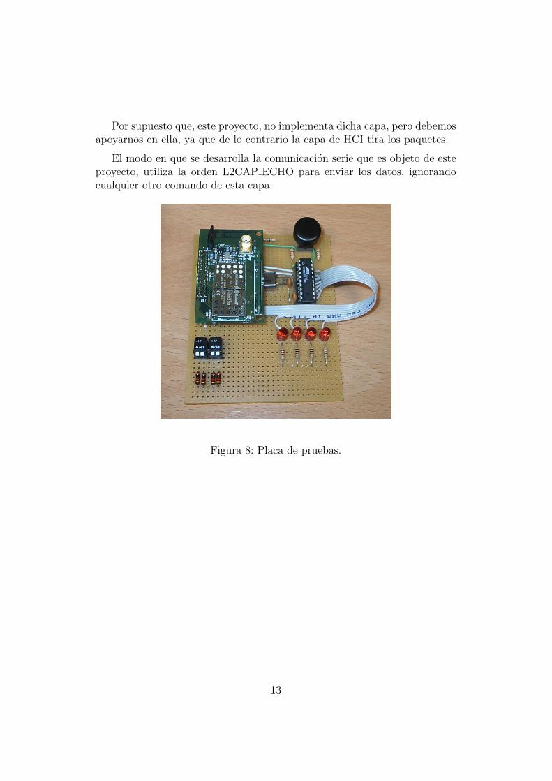
Por supuesto que, este proyecto, no implementa dicha capa, pero debemosapoyarnos en ella, ya que de lo contrario la capa de HCI tira los paquetes.
El modo en que se desarrolla la comunicacion serie que es objeto de esteproyecto, utiliza la orden L2CAP ECHO para enviar los datos, ignorandocualquier otro comando de esta capa.
Figura 8: Placa de pruebas.
13
3. Descripcion informatica.
3.1. Componentes.
A partir de aquı ya sabemos lo que queremos hacer, ahora solo quedaelegir los componentes adecuados para conseguir lo que nos proponemos. Loscomponemos necesarios son:
1. Un ordenador con capacidades Bluetooth. La mision de estesera ejecutar el programa que va a realizar la funcion de cliente quese conectara al 8051.
2. Una tarjeta hija de Bluetooth. Su funcion es la de recibir los datosque son transferidos.
3. Un 8051. Su mision es la de controlar la tarjeta hija de Bluetoothquedandole capacidad para realizar cualquier otra tarea.
3.1.1. Un ordenador con capacidades Bluetooth
El Ordenador del que estamos haciendo mencion en este punto debedisponer de capacidades Bluetooth, pero no de cualquier tipo de adapta-dor Bluetooth. Debe ser uno que disponga de comunicacion con el PC pormedio de UART ya que el programa que se ha desarrollado en este proyectono admite esta forma de comunicacion. Lo cual no quiere decir que el futuro,otro proyecto, adapte la programacion del actual y permita dicha opcion paraaprovechar los actuales adaptadores de Bluetooth de puerto serie, cada vezmas baratos y fiables
3.1.2. Una tarjeta hija de Bluetooth
Esta tarjeta es la tarjeta hija de Bluetooth del Starter Kit, la cual es real-mente el modulo que permite la comunicacion inalambrica. La tarjeta madreno es mas que un adaptador de tensiones entre el chip ROK y el puerto seriedel PC. Tambien es cierto que dispone de una fuente de alimentacion regu-lada y muy estable para la alimentacion del chip, ası como otros chips paradigitalizacion de sonido. Recordemos que Bluetooth es capaz de transmitirtanto datos como audio.
3.1.3. Un 8051
Este es el principal punto del proyecto ya que el 8051 no solo debe sercapaz de establecer la comunicacion con el PC a traves de Bluetooth, sino
14
que debe ser capaz de controlar el periferico que queremos controlar a travesdel PC.
En este proyecto tan solo nos encargamos de controlar un periferico tacito,es decir, simplemente vamos a colocar un par de leds para poder comprobarque la comunicacion entre PC y 8051 se realiza correctamente. En futurosproyectos tan solo debemos cambiar estos leds por el correspondiente periferi-co.
3.2. Especificacion
Tenemos 3 tipos de paquetes HCI: los comandos, los eventos (o respuestasdel chip Bluetooth) y los paquetes de datos.
Comandos:
Cabecera OpCode Tamano de los parametros Parametros1 byte 2bytes 1byte x bytes
Cuadro 3: Paquete de comando
Evento:
Cabecera OpCode Tamano de los parametros Parametros1 byte 1 byte 1byte x bytes
Cuadro 4: Paquete de evento
Datos:
Cabecera Connection Handle PB Flag BC Flag Tamano de los Datos Datos1 byte 12 bits 1 bit 1 bit 2 bytes X bytes
Cuadro 5: Paquete de datos
Es importante tener en cuenta que el chip ROK de Bluetooth trabaja conel formato de datos Little Endian por lo tanto a la hora de escribir datosde mas de 1 byte debemos escribir los bytes en orden inverso, es decir, sideseamos escribir el dato 4A2CH debemos escribir 2C4AH.
La cabecera es:
1. Comando: 01H
2. Evento: 04H
15
3. Datos: 02H
A continuacion veremos que el OpCode se compone de dos partes, el OCFque consta de 10 bits y el OGF de 6:
OpCodeOGF OCF
Cuadro 6: Paquete de datos
Lo mas sencillo sera hacer un ejemplo con el comando HCI Reset:
Segun el Core de Bluetooth su OCF o codigo de comando es el 0003H ysu OGF o codigo de grupo es el 03H
Si juntamos ambas partes el Opcode resultante es:
OGF (6 bits) OCF (10 bits)03 0003
00 0011 00 0000 00110000 1100 0000 0011
0C03
Cuadro 7: Paquete de datos
Observando la pagina del manual donde esta el HCI Reset observaremosque este comando no tiene parametros, por lo tanto, lo que debemos enviara la Bluetooth para realizar un reset sera:
Cabecera OpCode Tamano de los parametros Parametros01 030C 00
Cuadro 8: Paquete de datos
La secuencia a enviar, por tanto sera 01H,03H,0CH,00H
Preste especial atencion al OpCode. Hace un momento hemos dicho queel OpCode era 0C03H y ahora escribimos 030CH. No es un error, a esto es alo que me referıa con el formato Little Endian.
Continuando con el HCI Reset, observamos que el chip Bluetooth nosrespondera con un evento para indicarnos si ha ejecutado correctamente elHCI Reset o si ha tenido algun problema. Leyendo el manual, descubrimosque la Bluetooth nos va a responder con un HCI Command Complete.
16
El OpCode del HCI Command Complete es 0EH. En el caso de los Even-tos no hay grupos y al ser el codigo de un unico byte no hay lıos de formato.
El manual de Bluetooth nos indica que los parametros que devuelve unHCI Command Complete son los siguientes (el orden es importante):
Num HCI Command Packets (1 byte)
Command Opcode (2 bytes)
Return Parameters (x Bytes, depende del comando que lo genero)
Es importante destacar que el HCI Command Complete no solo se gen-era despues de un HCI Reset. Muchos otros comandos de HCI tienen comorespuesta un HCI Command Complete.
Veamos el aspecto que tendrıa la respuesta en este caso concreto:
04H, 0EH, 04H, 08H, 03H, 0CH, 00H
Donde:
Cabecera: 04H (indica Evento)
Opcode: 0EH (HCI Command Complete)
Tamano de los parametros: 04H (quedan 4 bytes de parametros)
Parametros: 08H 03H 0CH 00H (los parametros)
Y donde los parametros corresponden a:
Num HCI Command Packets: 08H (numero de comandos que le pode-mos enviar a la Bluetooth sin esperar respuesta)
Command Opcode: 030CH (Quien genero el evento)
Return Parameters: 00H (Status del HCI Reset, 00H= todo correcto)
Luego si el HCI Reset se completo con exito, recibiremos desde la Blue-tooth la siguiente cadena:
04H, 0EH, 04H, 08H, 03H, 0CH, 00H
En este apartado cabe destacar, por supuesto, dos partes. Por un ladodestacaremos la especificacion del lado del PC, o cliente, y por otro el ladodel 8051, o de servidor.
17
3.2.1. Lado Cliente o lado del PC
El lado del cliente el primer paso es buscar dispositivos Bluetooth queadmitan conexiones entrantes por medio de la orden HCI inquiry.
Una vez que sabemos que dispositivos hay en los alrededores, podemosconectarnos por medio de la orden HCI Create Connection y empezar lastransacciones de datos.
Este lado de PC, no tiene porque estar inicializado para permitir conex-iones entrantes, ya que no lo necesita, pero como este proyecto ha sido masde toma de contacto, tanto para mi, como para quien desee aprender la basede las comunicaciones de Bluetooth, dejaremos esta inicializacion ya que deeste modo, el apartado del servidor podrıa ser sustituido con otro PC, deforma que es mas sencillo ver todo el proceso de comunicacion Bluetooth.
Disponemos de las ordenes HCI Inquiry, HCI Create Connection, Enviode datos y HCI Disconect:
HCI InquiryVeamos en detalle la forma de ordenar el HCI Inquiry y como obtener las
respuestas (supondremos siempre codigo hexadecimal):
HCI Inquiry : 01 |01 |04 |05 |33 |8B |9E |08 |05
Con esta linea de comandos le estamos pidiendo a la Bluetooth que busquedispositivos Bluetooth que acepten conexiones entrantes hasta un maximo de5 dispositivos.
Una vez recibido este comando, la Bluetooth nos respondera con un even-to de HCI Command Status. Esto no quiere decir mas que ha aceptado elcomando.
Cuando encuentre algun dispositivo la Bluetooth nos envıa un HCI Inquiry Result.Segun el manual de Bluetooth, los dispositivos estan autorizados a enviar to-das las respuestas en un unico evento, enviando las respuestas con formade array, pero por suerte el ROK 101/007 y la tarjeta PCMCIA, envıan unHCI Inquiry Result por cada dispositivo encontrado.
Una vez encontrados los 5 dispositivos que le hemos pedido, o trascurridoel tiempo de TimeOut recibiremos un evento HCI Inquiry Complete
El evento HCI Inquiry Result tiene el siguiente aspecto:
En cuanto al tipo de paquetes, decir que hay varios tipos, pero son usadosen capas mas altas del stack Bluetooth, por lo tanto a nosotros nos vale conconocer este tipo que es el mas simple. Esta decision no influye en el formatode los paquetes a este nivel del stack.
Una vez que la Bluetooth recibe esta orden, inmediatamente nos indicapor medio de un evento de HCI Command Status que ha recibido la ordeny se pone manos a la obra. Cuando ha sido capaz de establecer la conexioncon el dispositivo solicitado, en ambos extremos de la comunicacion apareceun evento de HCI Connection Complete.
0100H: Connection handle (identificador de conexion)
F5A2C8A41000H: MAC del dispositivo
00H: Link Type (00H = Datos)
00H: Encriptacion (00H = deshabilitada)
Envıo de Datos
Una vez que hemos sido capaces de encontrar el dispositivo y establecerla comunicacion ya solo nos falta enviar los datos.
Como vimos antes el formato de los paquetes de datos es el siguiente:
Cabecera Connection Handle PB Flag BC Flag Tamano de los Datos Datos1 byte 12 bits 1 bit 1 bit 2 bytes X bytes
Cuadro 9: Paquete de datos
Hay que tener cuidado porque esto no es exactamente ası. En los Datosque aparecen deben corresponder con un paquete, perfectamente bien forma-do, de la capa siguiente, la L2CAP.
20
En esta capa disponemos de comandos para establecer nuevas conexionesde nivel superior, pero como lo que buscamos es simplicidad y tratar de nodistorsionar, en la medida de lo posible, otras comunicaciones Bluetooth,elegimos la orden L2CAP ECHO para enviar nuestros datos. De esta formaun paquete de datos quedaria ası:
Es decir, que podemos enviar hasta 4 bytes de datos siguiendo esta im-plementacion
Este formato de paquete es tanto de ida como de vuelta, me explico, si laotra parte de la conexion nos envıa un paquete de datos, lo recibiremos talcual, con la unica diferencia del ”Connection Handle” que podrıa ser distintoy coincidira con el asignado por el HCI Connection Complete.
HCI DisconectUna vez que hemos enviado los datos, podemos desconectarnos por medio
del comando HCI Disconnect de la siguiente forma:
Por ejemplo:
01 |06 |04 |03 |01 |00 |1F
Donde:
01H: Cabecera Comando
0604H: OpCode
03H: Longitud total de los parametros
21
0100H: Connection Handle
1FH: Razon ofrecida a la otra parte de la comunicacion (1FH = errorno especificado)
Una vez que el chip Bluetooth recibe este comando, inmediatamente nosenvıa un evento HCI Command Status, pero no podemos asegurar que la co-municacion se haya interrumpido hasta que no se recibe el HCI Disconnection Complete,que aparece en ambos extremos de la comunicacion.
3.2.2. Lado Servidor o lado del 8051
Lo mas importante a destacar del 8051 es su inicializacion como servidor,es decir, para permitir conexiones entrantes.
En la inicializacion lo que se hace es establecer los parametros de fun-cionamiento, pero no solo esto, tambien le damos a la BT ”patrones de con-ducta” para que reaccione por si misma sin molestarnos
Veamos detenidamente los principales comandos HCI de inicializacion
Comando DescripcionHCI Reset() Soft ResetHCI Set Event Filter(00) Limpiar el filtro de eventosHCI Write Scan Enable (03) Permite inquiry y Page ScanHCI Write Authentication Enable(00) Deshabilita la autenticacionHCI Write Voice Settings(0060) Especifica como seran las co-
municaciones de vozHCI Set Event Filter(02,00,02) Permitir conexiones desde
cualquieraHCI Write connection Accept timeout(1FA0) Timeout de conexionHCI Write page Timeout(2000) Timeout de escrituraHCI Change local name(nombre[248]) Informa a la BT de su nom-
bre
Cuadro 10: Secuencia de inicializacion
Veremos a continuacion la secuencia hexadecimal a enviar y una brevedescripcion de lo que estamos haciendo
22
HCI ResetSecuencia hexadecimal a enviar: 01 |03 |0C |00
Quiza el mas importante de todos los comandos ya que no debe faltar.
Este comando no tiene parametros, es tan solo un ”soft reset” para laBT. Vuelve a los valores por defecto al Host Controller, Link Manager y elmodulo de radio
Una vez finalizado el HCI Reset el Host Controller nos devuelve un
Evento de Command Complete para informarnos del estadoPrototipo de funcion:
Function HCI Reset (): status;
HCI Set Event FilterSecuencia hexadecimal a enviar:
Para el caso del parametro (00): 01 |05 |0C |01 |00
Para el caso del parametro (02,00,02): 01 |05 |0C |03 |02 |00 |02
Este comando nos permite indicarle a la BT con que Eventos puede ”molestarnos 2
con cuales no. En concreto con los Eventos generados cuando otra BT iniciaun proceso de Inquiry o de intento de conexion. Este comando nos permiteprogramar la BT para que responda automaticamente como nosotros quere-mos.
Justo despues del HCI Reset lo siguiente que debemos hacer es limpiarlas condiciones.
Esta funcion tiene 3 parametros de entrada.
Prototipo de funcion:
Function HCI Set Event Filter (Filter Type, Filter Condition Type, Con-dition): status
Filter Type:
Filter Condition TypePara Filter Type = 0x00
El resto de parametros se omite y no se envıan
23
Valor Descripcion0x00 Limpiar todos los filtros. En este ca-
so el resto de parametros se omiten0x01 Inquiry Result0x02 Connection Setup0x03 - 0xFF Reservado
Cuadro 11: Posibles valores de Filter Type
Valor Descripcion0x00 Responder a cualquier dispositivo nuevo0x01 Responder dependiendo del Class of Device0x02 Responder dependiendo de la MAC0x03 - 0xFF Reservado
Cuadro 12: Significado de Filter Condition Type si Filter Type vale 01H
Para Filter Type = 0x01 (inquiry Result)
Para Filter Type = 0x02 (Connection Setup)
Valor Descripcion0x00 Permitir conexion con cualquiera0x01 Permitir conexion dependiendo del Class of Device0x02 Permitir Conexion dependiendo de la MAC0x03 - 0xFF Reservado
Cuadro 13: Significado de Filter Condition Type si Filter Type vale 02H
Condition
Este parametro tiene diferente interpretacion y tamano dependiendo de
los elegidos anteriormentePara Filter Type = 0x01 (inquiry Result) Y Filter Condition Type =
0x00El parametro no se usa
24
Para Filter Type = 0x01 (inquiry Result) Y Filter Condition Type =
0x01El parametro Condition tiene un tamano de 6 Bytes repartidos en dos
partes de 3 Bytes
Valor Descripcion0x000000 Por defecto, Devuelve todos los dispositivos0xXXXXXX Class of Device determinado
Cuadro 14: Class Of Device: 3Bytes
Valor Descripcion0xXXXXXX Bit Mask usada para determinar el
Class of Device a los que no se leshace caso. 0 indica no importa
Cuadro 15: Bit Mask: 3 Bytes
Para Filter Type = 0x01 (inquiry Result) Y Filter Condition Type =
0x02El parametro Condition tiene un tamano de 6 bytes e indica la MAC
permitidaPara Filter Type = 0x02 (Connection Setup) Y Filter Condition Type
= 0x00El parametro condition tiene un tamano de 1 Byte
Valor Descripcion0x01 No aceptar conexiones automaticamente0x02 Aceptar conexiones0x03 Aceptar conexion con el flag switch role activado0x04 - 0xFF Reservado
Cuadro 16: Condition
25
Para Filter Type = 0x02 (Connection Setup) Y Filter Condition Type =0x01
El parametro condition tiene un tamano de 7 Bytes repartidos como
sigue
Valor Descripcion0x000000 Por defecto, Devuelve todos los dispositivos0xXXXXXX Class of Device en concreto
Cuadro 17: Class of Device: 3 Bytes
Valor Descripcion0xXXXXXX Bit Mask usada para determinar el
Class of Device a los que no se leshace caso. 0 indica no importa
Cuadro 18: Class Of Device Mask: 3Bytes
Valor Descripcion0x01 No aceptar conexiones automaticamente0x02 Aceptar conexiones0x03 Aceptar conexion con el flag switch role activado0x04 - 0xFF Reservado
Cuadro 19: Auto Accept Flag: 1 byte
Para Filter Type = 0x02 (Connection Setup) Y Filter Condition Type =0x02
El parametro Condition tiene un tamano de 7 bytes e indica la MAC
permitida y el Auto Accept Flag
26
Valor Descripcion0x01 No aceptar conexiones automaticamente0x02 Aceptar conexiones0x03 Aceptar conexion con el flag switch role activado0x04 - 0xFF Reservado
Cuadro 20: Auto Accept Flag: 1 byte
Una vez finalizado el HCI Set Event Filter el Host Controller nos de-
vuelve un Evento de Command Complete para informarnos del estado
Secuencia hexadecimal a enviar: 01 |13 |0C |F8 |Nombre[248])Nombre amigable con el que se identificara la BT en caso de que le
pregunten por el.Prototipo de funcion:
Function HCI Change local name (Name):status
Valor DescripcionSi el nombre contiene menos de
248 caracteres hay que rellenar con0x00 (NULL)
Cuadro 26: Name: 248Bytes
30
4. Conclusiones.
Dada la escasısima documentacion con la que contabamos al inicio deeste proyecto, unicamente los ”White Paper” que ofrece Bluetooth.org ensu pagina Web, el desarrollo de este proyecto ha sido, practicamente en sutotalidad, mediante ingenierıa inversa, es decir, espiando la comunicacion quese establece entre la tarjeta madre de Bluetooth y el programa de ejemploque nos ofrecıa el starter kit.
El principal logro que cabe destacar de este proyecto es, que si a penasdocumentacion hemos sido capaces de desarrollar una base de comunicacioninalambrica que puede ser aplicada a cualquier dispositivo basado en 8051unicamente anadiendo un chip ROK 101/007 de Ericsson.
——Conunicacion serie——
La utilidad de este proyecto esta justificada pues a partir de el, dada sugeneralidad, se puede construir la interface hardware para comunicacion in-alambrica mediante bluetooth de cualquier dispositivo considerado perifericoque realice operaciones de E/S de datos. En particular, ya se esta desarrol-lando, en otro proyecto, un transmisor inalambrico de electrocardiogramasen tiempo real para PDA’s, PC’s y telefonos moviles
31
5. Bibliografıa
* Bluetooth V1.1 Core Specifications: www.bluetooth.org
* Juego de instrucciones del microcontrolador 8051: www.8052.com
* LaTeX A document preparation system: www.latex-project.org
32
6. Apendices
Documentacion tecnica del Atmel AT89C2051
Documentacion tecnica del Ericsson ROK 101/007
33
8-bit Microcontroller with 2K Bytes Flash
AT89C2051
Features• Compatible with MCS-51™ Products• 2K Bytes of Reprogrammable Flash Memory
– Endurance: 1,000 Write/Erase Cycles• 2.7V to 6V Operating Range• Fully Static Operation: 0 Hz to 24 MHz• Two-level Program Memory Lock• 128 x 8-bit Internal RAM• 15 Programmable I/O Lines• Two 16-bit Timer/Counters• Six Interrupt Sources• Programmable Serial UART Channel• Direct LED Drive Outputs• On-chip Analog Comparator• Low-power Idle and Power-down Modes
DescriptionThe AT89C2051 is a low-voltage, high-performance CMOS 8-bit microcomputer with2K bytes of Flash programmable and erasable read only memory (PEROM). Thedevice is manufactured using Atmel’s high-density nonvolatile memory technologyand is compatible with the industry-standard MCS-51 instruction set. By combining aversatile 8-bit CPU with Flash on a monolithic chip, the Atmel AT89C2051 is a power-ful microcomputer which provides a highly-flexible and cost-effective solution to manyembedded control applications.
The AT89C2051 provides the following standard features: 2K bytes of Flash, 128bytes of RAM, 15 I/O lines, two 16-bit timer/counters, a five vector two-level interruptarchitecture, a full duplex serial port, a precision analog comparator, on-chip oscillatorand clock circuitry. In addition, the AT89C2051 is designed with static logic for opera-tion down to zero frequency and supports two software selectable power savingmodes. The Idle Mode stops the CPU while allowing the RAM, timer/counters, serialport and interrupt system to continue functioning. The power-down mode saves theRAM contents but freezes the oscillator disabling all other chip functions until the nexthardware reset.
Port 1 is an 8-bit bi-irectional I/O port. Port pins P1.2 toP1.7 provide internal pullups. P1.0 and P1.1 require exter-nal pullups. P1.0 and P1.1 also serve as the positive input(AIN0) and the negative input (AIN1), respectively, of theon-chip precision analog comparator. The Port 1 outputbuffers can sink 20 mA and can drive LED displays directly.When 1s are written to Port 1 pins, they can be used asinputs. When pins P1.2 to P1.7 are used as inputs and areexternally pulled low, they will source current (IIL) becauseof the internal pullups.
Port 1 also receives code data during Flash programmingand verification.
Port 3
Port 3 pins P3.0 to P3.5, P3.7 are seven bi-irectional I/Opins with internal pullups. P3.6 is hard-wired as an input tothe output of the on-chip comparator and is not accessibleas a general purpose I/O pin. The Port 3 output buffers cansink 20 mA. When 1s are written to Port 3 pins they arepulled high by the internal pullups and can be used asinputs. As inputs, Port 3 pins that are externally beingpulled low will source current (IIL) because of the pullups.
Port 3 also serves the functions of various special featuresof the AT89C2051 as listed below:
Port 3 also receives some control signals for Flash pro-gramming and verification.
RST
Reset input. All I/O pins are reset to 1s as soon as RSTgoes high. Holding the RST pin high for two machinecycles while the oscillator is running resets the device.
Each machine cycle takes 12 oscillator or clock cycles.
XTAL1
Input to the inverting oscillator amplifier and input to theinternal clock operating circuit.
XTAL2
Output from the inverting oscillator amplifier.
Oscillator Characteristics XTAL1 and XTAL2 are the input and output, respectively,of an inverting amplifier which can be configured for use asan on-chip oscillator, as shown in Figure 1. Either a quartzcrystal or ceramic resonator may be used. To drive thedevice from an external clock source, XTAL2 should be leftunconnected while XTAL1 is driven as shown in Figure 2.There are no requirements on the duty cycle of the externalclock signal, since the input to the internal clocking circuitryis through a divide-by-two flip-flop, but minimum and maxi-mum voltage high and low time specifications must beobserved.
Figure 1. Oscillator Connections
Note: C1, C2 = 30 pF ± 10 pF for Crystals= 40 pF ± 10 pF for Ceramic Resonators
Figure 2. External Clock Drive Configuration
Port Pin Alternate Functions
P3.0 RXD (serial input port)
P3.1 TXD (serial output port)
P3.2 INT0 (external interrupt 0)
P3.3 INT1 (external interrupt 1)
P3.4 T0 (timer 0 external input)
P3.5 T1 (timer 1 external input)
3
Special Function RegistersA map of the on-chip memory area called the Special Func-tion Register (SFR) space is shown in the table below.
Note that not all of the addresses are occupied, and unoc-cupied addresses may not be implemented on the chip.Read accesses to these addresses will in general return
random data, and write accesses will have an indetermi-nate effect.
User software should not write 1s to these unlisted loca-tions, since they may be used in future products to invokenew features. In that case, the reset or inactive values ofthe new bits will always be 0.
Table 1. AT89C2051 SFR Map and Reset Values
0F8H 0FFH
0F0H B00000000
0F7H
0E8H 0EFH
0E0H ACC00000000
0E7H
0D8H 0DFH
0D0H PSW00000000
0D7H
0C8H 0CFH
0C0H 0C7H
0B8H IPXXX00000
0BFH
0B0H P311111111
0B7H
0A8H IE0XX00000
0AFH
0A0H 0A7H
98H SCON00000000
SBUFXXXXXXXX
9FH
90H P111111111
97H
88H TCON00000000
TMOD00000000
TL000000000
TL100000000
TH000000000
TH100000000
8FH
80H SP00000111
DPL00000000
DPH00000000
PCON0XXX0000
87H
AT89C20514
AT89C2051
Restrictions on Certain Instructions The AT89C2051 and is an economical and cost-effectivemember of Atmel’s growing family of microcontrollers. Itcontains 2K bytes of flash program memory. It is fully com-patible with the MCS-51 architecture, and can beprogrammed using the MCS-51 instruction set. However,there are a few considerations one must keep in mindwhen utilizing certain instructions to program this device.
All the instructions related to jumping or branching shouldbe restricted such that the destination address falls withinthe physical program memory space of the device, which is2K for the AT89C2051. This should be the responsibility ofthe software programmer. For example, LJMP 7E0Hwould be a valid instruction for the AT89C2051 (with 2K ofmemory), whereas LJMP 900H would not.
1. Branching instructions:
LCALL, LJMP, ACALL, AJMP, SJMP, JMP @A+DPTR
These unconditional branching instructions will executecorrectly as long as the programmer keeps in mind that thedestination branching address must fall within the physicalboundaries of the program memory size (locations 00H to7FFH for the 89C2051). Violating the physical space limitsmay cause unknown program behavior.
CJNE [...], DJNZ [...], JB, JNB, JC, JNC, JBC, JZ, JNZ Withthese conditional branching instructions the same ruleabove applies. Again, violating the memory boundariesmay cause erratic execution.
For applications involving interrupts the normal interruptservice routine address locations of the 80C51 family archi-tecture have been preserved.
2. MOVX-related instructions, Data Memory:
The AT89C2051 contains 128 bytes of internal data mem-ory. Thus, in the AT89C2051 the stack depth is limited to128 bytes, the amount of available RAM. External DATAmemory access is not supported in this device, nor is exter-nal PROGRAM memory execution. Therefore, no MOVX[...] instructions should be included in the program.
A typical 80C51 assembler will still assemble instructions,even if they are written in violation of the restrictions men-tioned above. It is the responsibility of the controller user toknow the physical features and limitations of the devicebe ing used and ad jus t the i ns t ruc t i ons usedcorrespondingly.
Program Memory Lock BitsOn the chip are two lock bits which can be left unpro-grammed (U) or can be programmed (P) to obtain theadditional features listed in the table below:
Lock Bit Protection Modes(1)
Note: 1. The Lock Bits can only be erased with the Chip Erase operation.
Idle Mode In idle mode, the CPU puts itself to sleep while all the on-chip peripherals remain active. The mode is invoked bysoftware. The content of the on-chip RAM and all the spe-cial functions registers remain unchanged during thismode. The idle mode can be terminated by any enabledinterrupt or by a hardware reset.
P1.0 and P1.1 should be set to “0” if no external pullups areused, or set to “1” if external pullups are used.
It should be noted that when idle is terminated by a hard-ware reset, the device normally resumes programexecution, from where it left off, up to two machine cyclesbefore the internal reset algorithm takes control. On-chiphardware inhibits access to internal RAM in this event, butaccess to the port pins is not inhibited. To eliminate thepossibility of an unexpected write to a port pin when Idle isterminated by reset, the instruction following the one thatinvokes Idle should not be one that writes to a port pin or toexternal memory.
Power-down Mode In the power down mode the oscillator is stopped, and theinstruction that invokes power down is the last instructionexecuted. The on-chip RAM and Special Function Regis-ters retain their values until the power down mode isterminated. The only exit from power down is a hardwarereset. Reset redefines the SFRs but does not change theon-chip RAM. The reset should not be activated before VCCis restored to its normal operating level and must be heldactive long enough to allow the oscillator to restart andstabilize.
P1.0 and P1.1 should be set to “0” if no external pullups areused, or set to “1” if external pullups are used.
Program Lock Bits
LB1 LB2 Protection Type
1 U U No program lock features.
2 P U Further programming of the Flash is disabled.
3 P P Same as mode 2, also verify is disabled.
5
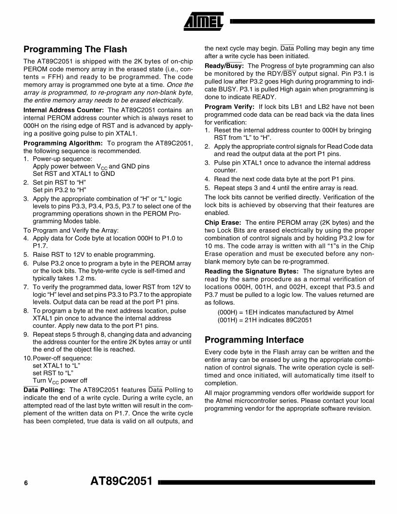
Programming The FlashThe AT89C2051 is shipped with the 2K bytes of on-chipPEROM code memory array in the erased state (i.e., con-tents = FFH) and ready to be programmed. The codememory array is programmed one byte at a time. Once thearray is programmed, to re-program any non-blank byte,the entire memory array needs to be erased electrically.
Internal Address Counter: The AT89C2051 contains aninternal PEROM address counter which is always reset to000H on the rising edge of RST and is advanced by apply-ing a positive going pulse to pin XTAL1.
Programming Algorithm: To program the AT89C2051,the following sequence is recommended.1. Power-up sequence:
Apply power between VCC and GND pinsSet RST and XTAL1 to GND
2. Set pin RST to “H”Set pin P3.2 to “H”
3. Apply the appropriate combination of “H” or “L” logic levels to pins P3.3, P3.4, P3.5, P3.7 to select one of the programming operations shown in the PEROM Pro-gramming Modes table.
To Program and Verify the Array:4. Apply data for Code byte at location 000H to P1.0 to
P1.7.5. Raise RST to 12V to enable programming.6. Pulse P3.2 once to program a byte in the PEROM array
or the lock bits. The byte-write cycle is self-timed and typically takes 1.2 ms.
7. To verify the programmed data, lower RST from 12V to logic “H” level and set pins P3.3 to P3.7 to the appropiate levels. Output data can be read at the port P1 pins.
8. To program a byte at the next address location, pulse XTAL1 pin once to advance the internal address counter. Apply new data to the port P1 pins.
9. Repeat steps 5 through 8, changing data and advancing the address counter for the entire 2K bytes array or until the end of the object file is reached.
10.Power-off sequence:set XTAL1 to “L”set RST to “L”Turn VCC power off
Data Polling: The AT89C2051 features Data Polling toindicate the end of a write cycle. During a write cycle, anattempted read of the last byte written will result in the com-plement of the written data on P1.7. Once the write cyclehas been completed, true data is valid on all outputs, and
the next cycle may begin. Data Polling may begin any timeafter a write cycle has been initiated.
Ready/Busy: The Progress of byte programming can alsobe monitored by the RDY/BSY output signal. Pin P3.1 ispulled low after P3.2 goes High during programming to indi-cate BUSY. P3.1 is pulled High again when programming isdone to indicate READY.
Program Verify: If lock bits LB1 and LB2 have not beenprogrammed code data can be read back via the data linesfor verification:1. Reset the internal address counter to 000H by bringing
RST from “L” to “H”.2. Apply the appropriate control signals for Read Code data
and read the output data at the port P1 pins.3. Pulse pin XTAL1 once to advance the internal address
counter.4. Read the next code data byte at the port P1 pins.5. Repeat steps 3 and 4 until the entire array is read.
The lock bits cannot be verified directly. Verification of thelock bits is achieved by observing that their features areenabled.
Chip Erase: The entire PEROM array (2K bytes) and thetwo Lock Bits are erased electrically by using the propercombination of control signals and by holding P3.2 low for10 ms. The code array is written with all “1”s in the ChipErase operation and must be executed before any non-blank memory byte can be re-programmed.
Reading the Signature Bytes: The signature bytes areread by the same procedure as a normal verification oflocations 000H, 001H, and 002H, except that P3.5 andP3.7 must be pulled to a logic low. The values returned areas follows.
Programming InterfaceEvery code byte in the Flash array can be written and theentire array can be erased by using the appropriate combi-nation of control signals. The write operation cycle is self-timed and once initiated, will automatically time itself tocompletion.
All major programming vendors offer worldwide support forthe Atmel microcontroller series. Please contact your localprogramming vendor for the appropriate software revision.
AT89C20516
AT89C2051
Notes: 1. The internal PEROM address counter is reset to 000H on the rising edge of RST and is advanced by a positive pulse at XTAL 1 pin.
2. Chip Erase requires a 10 ms PROG pulse.3. P3.1 is pulled Low during programming to indicate RDY/BSY.
Figure 3. Programming the Flash Memory Figure 4. Verifying the Flash Memory
Flash Programming and Verification Characteristics TA = 0°C to 70°C, VCC = 5.0 ± 10%
Symbol Parameter Min Max Units
VPP Programming Enable Voltage 11.5 12.5 V
IPP Programming Enable Current 250 µA
tDVGL Data Setup to PROG Low 1.0 µs
tGHDX Data Hold after PROG 1.0 µs
tEHSH P3.4 (ENABLE) High to VPP 1.0 µs
tSHGL VPP Setup to PROG Low 10 µs
tGHSL VPP Hold after PROG 10 µs
tGLGH PROG Width 1 110 µs
tELQV ENABLE Low to Data Valid 1.0 µs
tEHQZ Data Float after ENABLE 0 1.0 µs
tGHBL PROG High to BUSY Low 50 ns
tWC Byte Write Cycle Time 2.0 ms
tBHIH RDY/BSY\ to Increment Clock Delay 1.0 µs
tIHIL Increment Clock High 200 ns
AT89C20518
AT89C2051
Notes: 1. Under steady state (non-transient) conditions, IOL must be externally limited as follows:Maximum IOL per port pin: 20 mAMaximum total IOL for all output pins: 80 mAIf IOL exceeds the test condition, VOL may exceed the related specification. Pins are not guaranteed to sink current greater than the listed test conditions.
2. Minimum VCC for Power-down is 2V.
Absolute Maximum Ratings*Operating Temperature ................................. -55°C to +125°C *NOTICE: Stresses beyond those listed under “Absolute
Maximum Ratings” may cause permanent dam-age to the device. This is a stress rating only and functional operation of the device at these or any other conditions beyond those indicated in the operational sections of this specification is not implied. Exposure to absolute maximum rating conditions for extended periods may affect device reliability.
Storage Temperature ..................................... -65°C to +150°C
Voltage on Any Pinwith Respect to Ground .....................................-1.0V to +7.0V
Maximum Operating Voltage ............................................ 6.6V
DC Output Current...................................................... 25.0 mA
DC CharacteristicsTA = -40°C to 85°C, VCC = 2.0V to 6.0V (unless otherwise noted)
Note: 1. AC Inputs during testing are driven at VCC - 0.5V for a logic 1 and 0.45V for a logic 0. Timing measurements are made at VIH min. for a logic 1 and VIL max. for a logic 0.
Float Waveforms(1)
Note: 1. For timing purposes, a port pin is no longer floating when a 100 mV change from load voltage occurs. A port pin begins to float when 100 mV change frothe loaded VOH/VOL level occurs.
Serial Port Timing: Shift Register Mode Test ConditionsVCC = 5.0V ± 20%; Load Capacitance = 80 pF
Symbol Parameter
12 MHz Osc Variable Oscillator
UnitsMin Max Min Max
tXLXL Serial Port Clock Cycle Time 1.0 12tCLCL µs
tQVXH Output Data Setup to Clock Rising Edge 700 10tCLCL-133 ns
tXHQX Output Data Hold after Clock Rising Edge 50 2tCLCL-117 ns
tXHDX Input Data Hold after Clock Rising Edge 0 0 ns
tXHDV Clock Rising Edge to Input Data Valid 700 10tCLCL-133 ns
11
AT89C2051TYPICAL ICC - ACTIVE (85°C)
0
5
10
15
20
0 6 12 18 24
FREQUENCY (MHz)
ICC
mA
Vcc=6.0V
Vcc=5.0V
Vcc=3.0V
AT89C2051TYPICAL ICC - IDLE (85°C)
0
1
2
3
0 3 6 9 12
FREQUENCY (MHz)
ICC
mA
Vcc=6.0V
Vcc=5.0V
Vcc=3.0V
AT89C2051TYPICAL ICC vs. VOLTAGE- POWER DOWN (85°C)
0
5
10
15
20
3.0V 4.0V 5.0V 6.0V
Vcc VOLTAGE
ICC
µA
Notes: 1. XTAL1 tied to GND for ICC (power-down)2. P.1.0 and P1.1 = VCC or GND3. Lock bits programmed
Marks bearing ® and/or ™ are registered trademarks and trademarks of Atmel Corporation.
Terms and product names in this document may be trademarks of others.
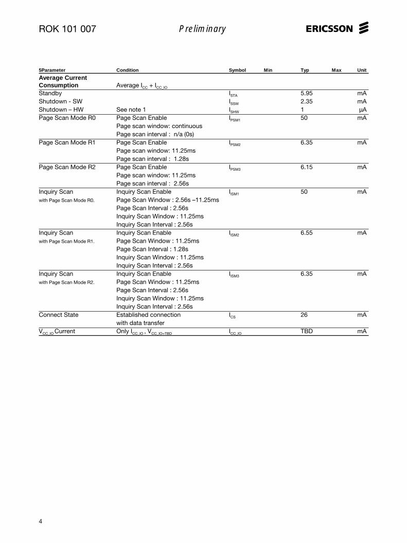
ROK 101 007Bluetooth Module
DescriptionROK 101 007 is a short-range module for implementing Bluetooth function-
ality into various electronic devices. The module consists of three major
parts; a baseband controller, a flash memory, and a radio that operates in the
globally available 2.4–2.5 GHz free ISM band.
Both data and voice transmission is supported by the module. Communica-
tion between the module and the host controller is carried out using a high-
speed USB interface compliant with USB Specifications 1.1 or an UART/
PCM interface. When using the USB interface, the module appears as a USB
slave device and therefore requires no PC resources.
ROK 101 007, which is compliant with Bluetooth version 1.0B, is a Class 2
Bluetooth Module (0 dBm) and is type-approved. The module supports all
Bluetooth profiles.
Key Features• Pre-qualified Bluetooth 1.0B Module
• RF output power class 2
• FCC and ETSI approved
• 460 kb/s max data rate over UART
• Multiple interface for different
applications
-UART for data
-PCM for voice
-USB for voice and data
• I2C interface
• Internal crystal oscillator
• HCI firmware included
• Multi Point Operation
• Built-in shielding
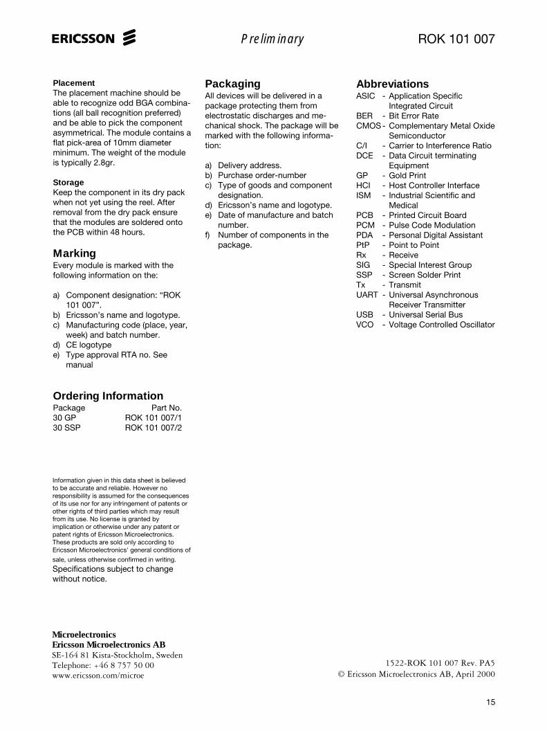
Suggested Applications• Computers and peripherals
• Handheld devices and accessories
• Access points
ROK 101 007
ROK 101 007
2
Preliminary
Figure 1. Block Diagram
Figure 2. Actual size of the Ericsson Bluetooth Module, and also showing the HW and FW stack.
RX-Balun
RadioASIC
ANTT2
TX-Balun
SwitchAntenna
Filter
LoopFilter
VCOTank
FLASHMemory
13MHzCrystal
VoltageRegulation
WAKE_UP
DETACH
GNDB3
R1
R2
T1
C6VCC
C4 VCC_IO
C2ON
RESET#
POR
NCNCNCNCNC
R4R5R6T4T5
T6C3
Radio Module
B4C1
ADDR
DATA
CTRL
R3
C5 NCPBA 313 01/2
Baseband
B1
D-
D+B2
USB
TXD
RTS
RXD
CTS
A5A6
B5
B6
UART
PCM_OUT
PCM_CLK
PCM_IN
PCM_SYNC
A1A2A3
A4
PCM T3
GND
GND
GND
GND
I2C_DATAI2C_CLK
01
23 cm
Radio
Baseband
Audio
Link Manager
HCI
ROK 101 007
3
Preliminary
Absolute Maximum RatingsParameter Symbol Min Typ Max Unit
TemperatureStorage temperature TStg -30 +85 °COperating temperature TAmb 0 +75 °CPower SupplyVCC VCC -0.3 +5.25 VVCC_IO VCC_IO -0.8 +3.6 VDigital InputsInput low voltage VIL -0.5 VInput high voltage VIH VCC_IO +0.3 V
Recommended Operating ConditionsTemperatureAmbient temperature, Test Tamb +23 °CPower SupplyPositive Supply Voltage VCC +3.3 VI/O Ports Supply Voltage VCC_IO +3.3 V
Electrical CharacteristicsDC SpecificationsUnless otherwise noted, the specification applies for TAmb = 0 to +75°C, 3.175 < VCC < 5.25VParameter Condition Symbol Min Typ Max Unit
Power SupplySupply Voltage VCC 3.175 3.3 5.25 VI/O Ports Supply Voltage See note 10 VCC_IO 2.7 3.3 3.6 VDigital InputsLogical Input High Except ON signal VIH1 0.7 x VCC_IO VCC_IO VLogical Input Low Except ON signal VIL2 0 0.3 x VCC_IO VLogical Input High ON signal only VIH2 2.0 VCC VLogical Input Low ON signal only VIL2 0 0.4 VDigital OutputsLogical Output High VOH 0.9 x VCC_IO VCC_IO VLogical Output Low VOL 0 0.1 x VCC_IO V
C/I BlockingThe blocking characteristics can bebasically split into two regions: In-band and Out-of-band. Blocking isperformed both on the chip and onthe module level.
• In-band– Filtering on chip– C/I @ 2MHz: -30 dB -> 0.1%BER– C/I ≥ 3MHz: -40 dB -> 0.1%BER
• Out-of-band– Antenna filter, DC to 1.9 GHz and
3:rd harmonic.– Switch, low freq. and 2:nd har-
monic.– RX-balun, low freq. and 2:nd
harmonic.– On-chip IF filter
Figure 6 shows the combinationblocking effect of the antenna switch,antenna filter and RX balun. Inaddition to the blocking characteris-tics shown in figure 6, there isantenna isolation and filtering on thechip.Marker 1 shows the region where theBluetooth band is located. Markers 2- 4 show the blocking at the telecomfrequency bands.An example of the total blockingcharacteristics can be seen in figure 7.
0.0 0.5 1.0 1.5 2.0 2.5 3.0 3.5 4.0 4.5 5.0
GHz
-100
-90
-80
-70
-60
-50
-40
-30
-20
-10
0
m1freq=2.450GHzdB( RX path)=-3.529
m1
m2freq=900.0MHzdB(RX path) = -74.580
m2
m3freq=1.800GHz
= -47.426
m3
m4freq=1.900GHz
) = -36.537
m4
dB(R
X p
ath)
dB(RX path)
dB(RX path
Figure 6. Typical blocking characteristics excluding antennaisolation and on chip filtering.
Example 2
Interference of +33 dBm at 1910 MHz.
Antenna isolation 25 dB
Antenna filter, 36 dB
Antenna switch,
RX-balun
Interference level before
IF filter +33-25-36= -28 dBm
0.1% BER carrier
level -40 + (-28)= -68 dBm
Example 1
Interference of +33 dBm at 2015 MHz.
Antenna isolation 15 dB
Antenna filter, 27 dB
Antenna switch,
RX-balun
Interference level before
IF filter +33-15-27= -9 dBm
0.1% BER carrier
level -40 + (-9)= -49 dBm
0.1% BER requires a C/I of more than -40 dB at the IF filter.
Figure 7. Blocking examples.
RF Specifications continued...
ROK 101 007
8
Preliminary
Pin DescriptionPin Pin Name Type Direction Description
A1 PCM_IN CMOS In PCM data, see notes 7,9A2 PCM_OUT CMOS Out PCM data, see notes 7,9A3 PCM_SYNC CMOS In/Out Sets the PCM data sampling rate, see notes 7,9A4 PCM_CLK CMOS In/Out PCM clock that sets the PCM data rate, see notes 7,9A5 RXD CMOS Input RX data to the UART, see note 9A6 RTS CMOS Input Flow control signal, Request To Send data from UART, see notes 7,9B1 D+ CMOS In/Out USB data pin, see notes 9,10B2 D- CMOS In/Out USB data pin, see notes 9,10B3 GND Power Power Signal groundB4 WAKE_UP CMOS Output Indicates that the module wants to be attached to the USB,
Active High. See notes 9,10B5 TXD CMOS Output TX data from the UART, see note 9B6 CTS CMOS Output Flow control signal, Clear To Send data from UART, see note 9C1 DETACH CMOS Input Indicates that the USB host wants to detach the module,
Active High. See notes 7,9C2 ON Power Input When tied to VCC, the module is enabled.C3 I2C_CLK CMOS Output I2C clock signal, see note 9C4 VCC_IO Power Power External supply rail to the Input / Output portsC5 NC - - Do not connectC6 VCC Power Power Supply VoltageR1 GND Power Power Signal groundR2 GND Power Power Signal groundR3 RESET# CMOS Input Active low reset, see notes 8,9R4 NC - - Do not connectR5 NC - - Do not connectR6 NC - - Do not connectT1 GND Power Power Signal GroundT2 ANT RF In/Out 50Ω Antenna connectionT3 GND Power Power Signal GroundT4 NC Power Power Test point, internal voltage regulator - Do not connectT5 NC - - Do not connectT6 I2C_DATA CMOS In/Out I2C data signal, see note 9
Notes1. Current consumption is based upon when the module is when ‘ON’ is low and ‘VCC_IO’ is grounded.2. During the TX mode, the VSWR specification states the limits that are acceptable before any other RF parameters
are strongly effected, i.e. frequency deviation and initial frequency error.3. Frequency deviation measurements are now recorded differentially, (f Mod1 - f Mod0 ) / 2.4. Provided that the TX INV register (bit 0) has been set in the enable register at startup.5. Tolerance for the system clock takes into account both the complete temperature range and aging of the crystal.6. LPO_CLK frequency is pre-trimmed within a tolerance of ±250ppm.7. 100kΩ pull-up resistors to VCC_IO are used on the module. PCM signals direction is programmable8. RESET# signal must be fed from an open drain output.9. CMOS buffers are low voltage TTL compatible signals.10. To be compliant with the USB specification, VCC_IO ≥ 3.11V
ROK 101 007
9
Preliminary
Figure 8. Mechanical dimensions.
Mechanical Specification
2.75
max
with
out
sold
er b
alls
Pad size: 35 mil = 0.889 mmTolerance on placement: 0.02 mm
app
rox
0.2
mm
Detail A
Detail A
16.8
0.2
0.54
0.2 Co-planarity 0.1 mm
9.47
32.8 0.2
14.1 0.2
7.85 0.2
1.6 0.2
15.7 0.214.1 0.2
7.85 0.2
5.05 0.2
T R CBA6
12345
5.72
6.98
22.2
223
.524
.76
1.6 0.2
3.124.395.666.938.2
ROK 101 007
10
Preliminary
USB
Control
VCC
Host
GND
BluetoothModule
Wake_up
Detach
GND
VCC_IO ON VCCD+
D-
4
4
RS 232transceiver
Codec PCM
UART
VCC_IO
VCC
RS232
GND
BluetoothModule
GND
VCC_IO ON VCC
ON
Application Block SchematicsUSB Application
Figure 9. A typical USB configuration.
Figure 10. A typical UART or PCM configuration.
UART and PCM Application
ROK 101 007
11
Preliminary
Functional DescriptionThe ROK 101 007 is a completeBluetooth module that has beenspecified and designed according tothe Bluetooth System v1.0B. Itsimplementation is based on a high-performance integrated radio trans-ceiver (PBA 313 01 /2) working with abaseband controller, a flash memoryand surrounding secondary compo-nents features low energy consump-tion for use in battery operateddevices.
Block DiagramROK 101 007 has five major opera-tional blocks. Figure 11 illustrates theinteraction of the various blocks. Thefunctionality of each block is asfollows:1. Radio functionality is achieved by
using the Bluetooth Radio, PBA313 01/ 2. Six operationalblocks are shown for the radiosection and their operation is asfollows:
1a) VCO-tank is a part of the phaselocked loop. The modulation isperformed directly on the VCO.To ensure high performance theVCO-tank is laser trimmed.
Figure 11. Simplified Block Diagram
RX-Balun
RadioASIC ANT
TX-Balun
Switch AntennaFilter
LoopFilter
VCOTank
Base-band
FLASHMemory
13MHzCrystal
VoltageRegulation
I2C Interface (2)
UART Interface (4)
PCM VoiceInterface (4)
POWER (3)
RESET
ADDR
DATA
CTRL
Radio Module
PBA 313 01/2
1
2
3
4
5
USB Interface (4)
1b) Loop filter, filters the tuningvoltage of the VCO-tank.
1c) RX-balun handles transformationfrom unbalanced to balancedtransmission.
1d) TX-balun handles biasing of theoutput amplifier stage andtransformation from balanced tounbalanced transmission.
1e) Antenna switch directs thepower either from the antennafilter to the receive ports or fromthe ASIC output ports to theantenna filter.
1f) Antenna filter band-pass filtersthe radio signal.
2. The baseband controller is anARM7-Thumb based chip thatcontrols the operation of theradio transceiver via one of theinterface methods; USB orUART. Additionally, the base-band controller has a PCM Voiceinterface and I2C interface.
3. A Flash memory is used togetherwith the baseband controller.Please, refer also to theFirmware section.
4. The power management blockregulates and filters the supplyvoltage. VCC is typically 3.3V andtwo regulated voltages areproduced, 2.8V and 2.2VNOM.
5. An internal clock is mounted onthe module. The clock frequencyis 13MHz and is generated froma crystal oscillator that guaran-tees a timing accuracy within± 20ppm.
Bluetooth Module stackThe Host Controller Interface (HCI)handles the communication by thetransport layer through the UART orUSB interface with the host. TheBaseband and radio provides asecure and reliable radio link forhigher layers.The following sections describe theBluetooth module stack in moredetail. It is implemented in accord-ance with and complies with theSpecification of the BluetoothSystem v1.0B.
Radio
Baseband
Audio
Link Manager
HCI
Figure 12. HW/FW parts included in the EricssonBuetooth module.
ROK 101 007
12
Preliminary
Bluetooth Radio InterfaceThe Bluetooth module is a class 2device with 4dBm maximum outputpower with no power control needed.Nominal range of the module with atypical antenna is up to a range of 10m (at 0 dBm). It is compliant withFCC and ETSI regulations in the ISMband.
BasebandBluetooth uses an ad-hoc netstructure with a maximum of eightactive units in a single piconet. Bydefault the first unit setting up aconnection is the master of the pointto point link. The master transmits inthe even timeslots and the slavetransmits in the odd timeslots.
For full duplex transmission, a Time-Division Duplex (TDD) scheme isused. Packets are sent over the air intimeslots, with a nominal length of625 µs. A packet can be extended toa maximum of 5 timeslots (DM5 and
DH5 packets) and is then sent byusing the same RF channel for theentire packet.
Two types of connections areprovided - AsynchronousConnectionless Link (ACL) for dataand the Synchronous ConnectionOriented Link (SCO) for voice. Three64 kb/s voice channels can besupported simultaneously. Further-more, there are also packages usedfor link control purposes.
A variety of different packet typeswith error correction schemes anddata rates can be used over the airinterface. Also asymmetric communi-cation is available for high speedcommunication in one direction.
The Baseband provides the link-setup and control routines for thelayers above. Furthermore, theBaseband also provides Bluetooth
security like encryption, authentica-tion and key management.
Please refer to the Specification ofthe Bluetooth System v1.0B part Bfor in-depth information regarding theBaseband.
Firmware (FW)The module includes firmware for thehost controller interface, HCI, and thelink manager, LM.The FW resides in the Flash and isavailable in object code format.
Link Manager (LM)The Link Manager in each Bluetoothmodule can communicate withanother Link Manager by using theLink Manager Protocol (LMP) whichis a peer to peer protocol.The LMP messages have the highestpriority and are used for link-setup,security, control and power savingmodes. The receiving Link Manager
User Payload Symetric AsymetricType (bytes) FEC CRC Max. rate Max.rate
ID na na na na na
NULL na na na na na
POLL na na na na na
FHS 18 2/3 yes na na
Link control packets
Asymetric Payload User Symetric Max rate (kb/s)Header Payload Max. rate
Type (bytes) (bytes) FEC CRC (kb/s) Forward Reverse
DM1 1 0-17 2/3 yes 108.8 108.8 108.8
DH1 1 0-27 no yes 172.8 172.8 172.8
DM3 2 0-121 2/3 yes 258.1 387.2 54.4
DH3 2 0-183 no yes 390.4 585.6 86.4
DM5 2 0-224 2/3 yes 286.7 477.8 36.3
DH5 2 0-339 no yes 433.9 723.2 57.6
AUX1 1 0-29 no no 185.6 185.6 185.6
ACL packets
SymetricPayload header User Payload Max. rate
Type (bytes) (bytes) FEC CRC (kb/s)
HV1 na 10 1/3 no 64.0
HV2 na 20 2/3 no 64.0
HV3 na 30 no no 64.0
DV 1D 10+(0-9) D 2/3 D Yes D 64.0+57.6 D
SCO packets
LMLM
LC
RF
LC
RF
LMP
Physical layer
Table 1: Link Control Packets Table, ACL Packets Table, SCO packets
Figure 13. Link manager
filter-out the message and does notneed to acknowledge the messageto the transmitting LM due to thereliable link provided by theBaseband and radio.
LM to LM communication can takeplace without actions taken by thehost. Discovery of features at otherBluetooth enabled devices nearbycan be found and saved for later useby the host.
Please refer to the Specification ofthe Bluetooth System v1.0B part Cfor in-depth information regardingthe LMP.
ROK 101 007
13
Preliminary
Figure 14. PCM timing
Table 2. PCM parameters
Host Control Interface (HCI)The HCI provides a uniform com-mand I/F to the Baseband and LinkManager and also to HW statusregisters.
There are three different types of HCIpackets:
• HCI command packets – fromhost to Bluetooth module HCI.
• HCI event packets – fromBluetooth module HCI to host.
• HCI data packets – going bothways.
It is not necessary to make use of alldifferent commands and events foran application. If the application isaimed at a pre-specified profile, thecapabilities of such a profile isnecessary to adjust to – see Specifi-cation of the Bluetooth System v1.0BProfiles.
a) With the HCI UART TransportLayer on top of HCI, the modulewill communicate with a hostthrough the UART I/F. The PCM I/F is also available for communi-cating voice.
b) With the HCI USB TransportLayer on top of the HCI, themodule will communicate with ahost through the USB. Detachand Wake_up signals are alsoavailable for notebook implemen-tations.
Please refer to the Specification ofthe Bluetooth System v1.0B part H:1-4 for in-depth information regardingthe HCI and different transport layers
Module HW InterfacesUART InterfaceThe UART implemented on themodule is an industry standard16C450 and supports the followingbaud rates: 300, 600, 900, 1200,1800, 2400, 4800, 9600, 19200,38400, 57600, 115200, 230400 and460800 bits/s. 128 byte FIFOs areassociated with the UART.
Four signals will be provided for theUART interface. TxD & RxD are usedfor data flow, and RTS & CTS is usedfor flow control.
Please refer to the Specification ofthe Bluetooth System v1.0B part H:4regarding the HCI and UART trans-port layers.
PCM Voice InterfaceThe standard PCM interface has asample rate of 8 kHz (PCM_SYNC).The PCM clock is variable between200 kHz and 2.0MHz. The PCM datacan be linear PCM (13-16bit), µ-Law(8bit) or A-Law (8bit).
The PCM I/F can be either master orslave – providing or receiving thePCM_SYNC. Redirection ofPCM_OUT and PCM_IN can beaccomplished as well.
Over the air the encoding is program-mable to be CVSD, A-Law or µ-Law.Preferably the robust CVSD encodingshould be used.
USB InterfaceThe module is a USB high-speedclass device (12Mbps) that has the
full functionality of a USB slave andis compliant to the USB 1.1 specifi-cation. Data transfer occurs on thebi-directional ports, D+ & D-.
Additionally, there are two side bandsignals for a notebook application.Two side band signals Wake_up andDetach are used to control the statefrom which the notebook resumes.When the host is in a power downmode, Wake_up wakes the host upwhen the Bluetooth system receivesan incoming connection. The hostindicates that it is in Suspend modeby using the Detach signal.
I2C InterfaceA master I2C I/F is available on themodule. The control of the I2C pinsare performed by Ericsson specificHCI commands available in the FWimplementation – see Appendix C.
MSB MSB-1 MSB-2
PCM_CLK
PCM_SYNC
PCM_X in
PCM_X out
tPSS
tPSH
tDSL
tDSH
tPDLP
MSB MSB-1 MSB-3MSB-2
Name Description Min Typ Max UnitfpcmClk PCM data-transfer clock frequency 1 128 2000 kHzfpcmSync PCM sample rate sync. frequency 8 kHztCCH PCM_CLK high period 200 nstCCL PCM_CLK low period 200 nstPSS PCM_SYNC (setup) to PCM CLK (fall) 100 nstPSH PCM_SYNC pulse length 200 nstDSL PCM_X in (setup) to PCM_CLK (fall) 100 nstDSH PCM_X in (hold) from PCM_CLK (fall) 100 nstPDLP PCM_X out valid from PCM_CLK (rise) 150 ns
ROK 101 007
14
Preliminary
AntennaThe ANT pin should be connected toa 50Ω-antenna interface, therebysupporting the best signal strengthperformance. Ericsson Microelec-tronics can recommend applicationspecific antennas – see Appendix C.
Power-up Sequence
There is no need for a power upsequence if VCC, ON and VCC_IOare tied together.
A power up sequence, if used, shallbe applied accordingly: Connectionof the supply rails, GND and thenVCC; then the ON signal should beapplied in order to initiate the internalregulators; and finally, the VCC_IO
supply rail can be activated.
The power-down sequence is similarto the power-up procedure but in thereverse format. Therefore, thedisconnection of the signals shall beas follows: VCC_IO, ON,VCC and finallyGND.
RESET#The assignment of the RESET# inputis to generate a reset signal to thecomplete Bluetooth module. Duringpower-up the reset signal is set ‘low’automatically so that power supplyglitches are avoided. Therefore noreset input should be required afterpower-up.When implementing an externalRESET#, the signal should be fedfrom an open drain output.
PowerThere are three inputs to the VoltageManagement section (VCC, VCC_IO,ON). VCC is the supply voltage that istypically 3.3V.
A separate power supply rail (VCC_IO)is provided for the I/O ports, UART,PCM and USB. To be compliant withthe USB 1.1 specification, VCC_IO >3.11V. VCC_IO can either be connectedto VCC or to a dedicated supply rail,which is the same as the logicalinterface of the host.
VCC
ON
VCC_IO
td_VCC_IO_o td_VCC_IO_o
ff
td_offtd_ontd
tr
tr_ont
tf_on
Parameter Min Nom Max Unit
tr 1 ms
tr_on 60 µs
tf_on 60 µs
td_on tr µs
td_off µs
tdvcc_io_on td_on µs
tdvcc_io_off td_off µs
Figure 15. Power up sequence
Table 3. Power up parameters
Shielding / EMC RequirementsThe module has its own RF shieldingand is approved according to thestandards by FCC and ETSI.
If the approval number is not visibleon the outside when the module isutilized in the final product, anexterior label must state that there isa transmitter module inside theproduct.
GroundGround should be distributed withvery low impedance as a groundplane. Connect all GND pins to theground plane.
Assembly GuidelinesSolder PasteThe ROK 101 007 module is madefor surface mounting and the SSPconnection pads have been formedafter printing eutectic Tin/Lead solderpaste. The solder paste to use is notcritical as long as this is a normal
eutectic solder paste. A preferredsolder paste height is 150µm.
Soldering ProfileIt must be noted that the moduleshould not be allowed to be hangingupside down in the re-flow operation.This means that the module has tobe assembled on the side of the PCBthat is soldered last.
The re-flow process should be aregular surface mount solderingprofile (full convection stronglypreferred); the ramp-up should notbe higher than 2oC/s and with a peaktemperature of 210-235oC during 20-60 seconds.
Pad SizeIt is recommended that the pads onthe PCB should have a diameter of0.7-0.9 mm. The surface finish on thePCB pads should be Nickel/Gold or aflat Tin/Lead surface or OSP (OrganicSurface Protection).
ROK 101 007
15
Preliminary
PlacementThe placement machine should beable to recognize odd BGA combina-tions (all ball recognition preferred)and be able to pick the componentasymmetrical. The module contains aflat pick-area of 10mm diameterminimum. The weight of the moduleis typically 2.8gr.
StorageKeep the component in its dry packwhen not yet using the reel. Afterremoval from the dry pack ensurethat the modules are soldered ontothe PCB within 48 hours.
MarkingEvery module is marked with thefollowing information on the:
a) Component designation: “ROK101 007”.
b) Ericsson’s name and logotype.c) Manufacturing code (place, year,
week) and batch number.d) CE logotypee) Type approval RTA no. See
manual
Ordering InformationPackage Part No.30 GP ROK 101 007/130 SSP ROK 101 007/2
PackagingAll devices will be delivered in apackage protecting them fromelectrostatic discharges and me-chanical shock. The package will bemarked with the following informa-tion:
a) Delivery address.b) Purchase order-numberc) Type of goods and component
designation.d) Ericsson’s name and logotype.e) Date of manufacture and batch
Information given in this data sheet is believedto be accurate and reliable. However noresponsibility is assumed for the consequencesof its use nor for any infringement of patents orother rights of third parties which may resultfrom its use. No license is granted byimplication or otherwise under any patent orpatent rights of Ericsson Microelectronics.These products are sold only according toEricsson Microelectronics' general conditions of
sale, unless otherwise confirmed in writing.
Specifications subject to changewithout notice.
AbbreviationsASIC - Application Specific
Integrated CircuitBER - Bit Error RateCMOS - Complementary Metal Oxide
SemiconductorC/I - Carrier to Interference RatioDCE - Data Circuit terminating
MedicalPCB - Printed Circuit BoardPCM - Pulse Code ModulationPDA - Personal Digital AssistantPtP - Point to PointRx - ReceiveSIG - Special Interest GroupSSP - Screen Solder PrintTx - TransmitUART - Universal Asynchronous
Receiver TransmitterUSB - Universal Serial BusVCO - Voltage Controlled Oscillator
ROK 101 007
16
Preliminary
APPENDIX AGetting StartedThe ROK 101 007 Bluetooth moduleis easy to use when designing aBluetooth application. However,there is a need for know-how in theBluetooth System specification v1.0Bas well as the Profile specificationv1.0B when designing and end-customer product.
• Bluetooth module• Know-how in Bluetooth specifica-
tion regarding HCI commands• Test board with UART/PCM or
USB I/F• Visual C++ for PC SW design• Preferably HCIdriver, L2CAP,
RFCOMM and SDP from Ericsson
The list above show some parts thatwould make designing convenient.
All information needed, regardinghow to drive the HCI over UART isspecified in part H4 of the BluetoothSystem v1.0B further more part H1and also Appendix IX with messagecharts is relevant.
Below follow an example of how toset up an ACL link between toBluetooth modules by using theUART I/F and also a schematic ofhow to interface the module andcontrol it by a host, normally a PC ormicrocontroller.
Principle schematic forUART inter- connectThe inter-connection to the level-shifter when designing a test-boardcould be according to the schematicbelow. (Figure A1.)
The Bluetooth module can beconnected as a DCE/DTE and amodem/nullmodem cable couldtherefor be used in-between the test-board and the PC.
Setting up a Bluetoothpoint-to-point connectionThe Host Controller Interface (HCI) inthe module is a command I/F. Thehost presents commands to the HCIand receives events back from theHCI of the module. The module LinkManager provides link set up capa-bility to the HCI.
• Host_B Bluetooth module is set in
paging scan mode – listening for
a Bluetooth device asking for a
new connection
• Host_A Bluetooth module is set in
paging mode asking for a con-
nection to Host_B
This is accomplished by first settingup the connection between the Hostand the module and thereaftercreating the connection between themodules using HCI commands.
V+
MAX3232E
V-
+-
RS-232
+-
CX
CX
10
11
9
12
100nF
100nF
1
3
4
5
2
6
100nF
100nF
VCC
7
14
8
13
9-pin D-sub
2 RXD
8 CTS
3 TXD
7 RTS
BLUETOOTHMODULE
ROK 101 007
B5
B6
A5
A6
TXD
CTS
RXD
RTS
16VCC
15GND
100nF
The capacitor values arechosen for a VCC from3.2 to 3.6 V
VCC
VCC VCC_IO ON
Figure A1. Bluetooth module connected as a DCE through level shifter
Figure A2. Bluetooth host to host communication
ROK 101 007
17
Preliminary
Host set-up via UART:There are 4 different types of HCI-packets accepted on the UART I/F.
• Read_Buffer_Size: Providing the
host with information on buffer
size for ACL and SCO data
packets for the module returned
with a
Command_Complete_Event
packet. The host shall use this
information for controlling the
transmission
• Host_Buffer_Size: Providing the
module with information on buffer
size for ACL and SCO packets to
the host.
It is the host that manages the databuffers of the Host Controller on themodule.
TimersIt could be necessary to set impor-tant timers used by the module fortime out handling. The timers are allset by writing to registers using HCIcommands.
The default values can be checked inSpecification of the BluetoothSystem v1.0B part H:1 or by usingRead_xxx_xxx commands.
Bluetooth AddressThe hosts, using the HCI commandRead_BD_ADDR will find theBluetooth address of the module bythe Command_Complete_Event withthe BD_ADDR as a parameter.
By Remote_Name_Request, theBD_ADDR of the remote module canalso be found.
InquiryThe HCI command Inquiry with theparameters LAP, Inquiry_Length, andNum_Responses can also be usedfor collecting BD_ADDR of remoteBluetooth units.
Creating a Point-to-pointconnectionPage Scan mode
HCI packet type HCI packet indicatorHCI command packet 0x01HCI ACL data packet 0x02HCI SCO data packet 0x03HCI event packet 0x04
The HCI packet indicator shall besent immediately before the HCIpacket. When the entire HCI packethas been received a new indicatorshould be expected.
The default speed setting is 57.6 kb/sand can be changed by sending aspecified bit stream to the I/F - seeAppendix C on how to change thespeed setting of the UART.
When the speed set-up for the UARTis made for both Host_ A & B, theCommand Packets can be sent andEvent Packets received by the hosts.See HCI over UART in part H:4 of theBluetooth System v1.0B for detailedinformation regarding parametersand protocol.
Soft ResetFirst HCI command packet to sendshould be the RESET packet.
A Command_Complete_Event with astatus parameter should be returnedto the host.
Buffer informationBuffer information should be ex-changed between the module andrespective host by using HCI com-mands.
Command ReturnCommand OCF parameters parametersHCI_Write_Scan_Enable 0x0005 Scan_Enable Status
To set a Bluetooth module in themode for being able to connect to(Host_B), page scan mode, there aresome settings that should be per-formed.
The Write_Scan_Enable commandwith correct parameter(Scan_Enable=0x001A) will set themodule in Page scan mode if theCommand_Complete_Event issuccessful.
Furthermore the setting of authenti-cation and encryption should bedisabled (default) by using the:• Write_Authentication_Enable
• Write_Encryption_Mode
The basic settings for getting intoscan mode could be according to thebelow suggested script list.• Read Buffer Size
• Set Event Filter
• Write Scan Enable: (Scan Enable:
0x03)
• Write Voice Setting: (Voice
Channel Setting: 0x0060)
• Write Authentication Enable:
(Authentication Enable: 0x00)
Table A1. HCI packets
Table A2. HCI Write Scan EnableOCF code
ROK 101 007
18
Preliminary
• Set Event Filter: (Connection
Setup Filter: Connections from All
Devices, Auto Accept: 0x02)
• Write Connection Accept
ACL link up and runningHost_A is the master of the point-to-point piconet and Host_B is slave.The unit starting the paging processis by definition the master. The linkset-up is completed when the eventConnection_Complete_Event isreturned to both Host_A and Host_Bwith the connection handle as one ofthe parameters and the statusparameter 0x00 (success). WhenBluetooth link is up and running theHCI data packets can be sent fromhost to host.
The host must take care of generat-ing the packages going from Host toHost Controller in the module overthe UART I/F, in the same way theHost must arrange the packagesreceived from the Host Controller.
Both sides need information on whatkind of data is received, to be able tointerpret the bit flow correctly.
For extensive information on settingup a Bluetooth link please refer toBluetooth System v1.0B Appendix IXMessage Sequence Charts
Adding an SCO linkWhen creating a voice connectionusing the PCM I/F, an ACL link mustbe up and running between the twodevices, an SCO link can thereafterbe added.
The control of the PCM I/F (FS,PCM_IN/OUT and PCM_CLK) ishandled by Ericsson specific HCIcommand – see Appendix C.
Driving SWHCI- APIThe Bluetooth module includes allHCI command capabilities accordingto Bluetooth System v1.0B. Further-more, there is some Ericsson specificcommands available for accessingHW registers and HW control – seeAppendix C. SW for driving themodule should be developed for theHCI interface.
There is source code SW availablewith Ericsson Bluetooth DevelopersKit (EBDK), see Appendix B, whichcan be used for driving the module.This SW comes with the EBDK andhas an HCI-API for applicationdevelopment on the HCI I/F.
Higher layer-APISoftware (HCIdriver, L2CAP,RFCOMM and SDP) are available in ageneric, source code format, i.e. tobe adapted to various operatingsystems.
• HCIdriver – implements the HCI
command driver used by the host
• L2CAP – handles protocol
multiplexing, segmentation and
re-assembly of packets
• RFCOMM – provides a serial port
emulation over the L2CAP
protocol
• SDP – Service Discovery Protocol
provides information on the
services available on a Bluetooth
device
Additional SW for the applicationshall be developed for the actualapplication on top of the RFCOMMAPI. If the application is according toa SIG predefined profile, it should beimplemented accordingly. Newapplications can be the driver of thespecification of new profiles decidedby the SIG – see Specification of theBluetooth System v1.0B Profiles.
0 4 8 12 16 20 24 32Connection handle PB BC Data total length
Flag Flag
Data
Timeout: (Connection Accept
Timeout: 0x2000)
• Write Page Timeout: (Page
Timeout: 0x3000)
Page modeThe Create_Connection command isused to set-up a link to anotherBluetooth device.
This command will cause the LinkManager to try to create a connec-tion to the Bluetooth module with theappropriate BD_ADDR. The localBluetooth module (Host_A) starts thepaging process to set up a link to thepage-scanning remote device(Host_B).
By LMP the negotiation between thetwo Bluetooth modules Link Manag-ers (LM) the link set-up can becompleted.
APPENDIX BDevelopment toolsEricsson Bluetooth DevelopmentKit (EBDK)The easiest way of getting started isto use the Ericsson BluetoothDevelopers Kit. It provides all partsnecessary for developing applica-tions for the Bluetooth module.
Available are:• PC plug&play
• Demos using radio/baseband
• Macro capability
• C++ v5.0 Source code for use in
applications
• HCIdriver, L2CAP, SDP and
RFCOMM for applications using
UART communication
• Pins for electrical measurements
• Antennas
Development can easily take placeon the EBDK platform and thereafterthe implementation of the fullBluetooth capability can be setup bydeveloped SW/HW and the Bluetoothmodule.
Software (HCIdriver, L2CAP,RFCOMM and SDP) will be availablein source code for PC.
• HCIdriver – implements the HCI
command driver used by the host
• L2CAP – handles protocol
multiplexing, segmentation and
re-assembly of packets
• RFCOMM – provides a serial port
emulation over the L2CAP
protocol
• SDP – Service Discovery Protocol
provides information on the
services available on a Bluetooth
device
Technical support is available fromthe EBDK distributor. Please contactEricsson Microelectronics for order-ing and information regarding the
EBDK and regarding extra daughterboard with ROK 101 007 as add-onto the EBDK.
Ericsson Bluetooth Starter Kit (EBSK)A very small convenient kit, whichpreferably is used in point-to-multipoint configuration designs,
based on the Bluetooth module ROK101 007.
Please contact Ericsson Microelec-tronics for ordering and informationregarding the Ericsson BluetoothStarter Kit.
Base Band Board
Application Board
Radio Board
JTAG
I2C
A udioUSB
Mo
nito
rin
g p
ins
RS-232 RS-232 RS-232
Ericsson BaseBand
Ericsson RadioModule
Ad
dre
ss /
Data
/ C
on
tro
l
USB9602 MS7540
Radio Board (0dBm)
Er icsson RadioModule
Radio Board (20dBm)
Er icsson RadioModule
optional external antenna
GLUE LOGIC (XLI NX)
LEDS
Memor yMemory
EBDK
AudioRS-232 USB
Ericsson BluetoothModule ROK 101 007/1
Codec
Power
DC/DCLevel-shift
EBSK
Figure B1. Ericsson Bluetooth Development Kit (EBDK)
Figure B2. Ericsson Bluetooth Starter Kit (EBSK)
ROK 101 007
20
Preliminary
APPENDIX CBluetooth InformationThis part will be updated and newinformation will be added continu-ously.
RadioFast Frequency hopping (1600chan-nel hop/s) with 79(23) channelsavailable (2.402 to 2.480 GHz) and asymbol rate of 1Ms/s over the airexploits the maximum channelbandwidth in the unlicensed ISMband.
To sustain a high transfer rate in busyradio environment, the frequencyhopping together with advancedcoding techniques maximizes thethroughput.
During Page and Inquiry the hoppingfrequency is risen to 3200 hops/s toenhance the time needed for connec-tion set-up.
Modulation technique is a binaryGaussian Frequency Shift KeyingGFSK, with a BT product of 0.5. Thechannel bandwidth is 1 MHz and thefrequency deviation from the carrierfrequency of the RF channel isbetween +/-140 to +/-175 kHz forrepresenting a ‘1’/’0’.
A rapid process is ongoing toharmonise Spanish, French andJapanese frequency ranges with therest of the world.
Data and parameter formatsThere are exceptions in the Bluetoothsystem for data and parameterformats – general rules below.• All values are in Binary and
Hexadecimal little Endian formats
• Negative values must use 2’s
Country Frequency range RF channels
Europe & USA 2400-2483.5 MHz f = 2402 + k MHz k = 0....78Japan 2471-2497 MHz f = 2473 + k MHz k = 0....22Spain 2445-2475 MHz f = 2449 + k MHz k = 0....22France 2446.5-2483.5 MHz f = 2454 + k MHz k = 0....22
Table C1. Frequency ranges used.
complement format
• Array parameter notation is
parameterA[i], parameterB[i],…• Allparameter values are sent/received inlittle Endian format. The least signifi-cant byte is sent first – unless notedotherwise.
HCI OpcodesThe Opcodes have been changedduring the ongoing standardisationwork. Below is the description onhow to send opcodes to the module.
Below is the general HCI command
HCI_Inquiry_Cancel (Example):
OGF: 0x01bin: 0000 0001
OCF: 0x0002bin: 0000 0000 0000 0010
Real code bin: 0000 01 | 00 0000 0010
LINK CONTROL COMMAND
0 x 0 4 0 2
Sent to module in hex: 02 04 00
Reverse byte order
Zero parameters
lsb lsbmsbmsb
msb lsb
OpCode
OCF OGF
ParameterTotal length
OpCode CommandField10 bits
OpCode GroupField6 bits
Little Endian
OGFRange (6 bits): 0x00-0x3F 0x3E: Bluetooth logo testing0x3F: Vendor specific debug commands
packet format depicted as well as abyte order description.
UART speed settingThe baud rate is changed with anEricsson specific HCI command.HCI_Ericsson_Set_Uart_Baud_Rate
The command has one parameter,baud rate - one byte long accordingto the table below . The op-code forthe command is 0xfc07 - the lastfigure is due to a possible change.
Sending the command should beperformed accordingly: 07 fc 01 yz ,where yz is the chosen baud ratefrom the table.
The op-code is sent in reverse byteorder. 01 is the parameter length, inthis case one byte. Remember to addthe HCI packet indicator.
Observe - When changing the baudrate for the module the host also hasto change the baud rate.
Observe - Removing power to themodule the baud rate will be reset to57.6 kbps.
Observe -Two zeros are not printedin the beginning of the binary param-eters below. The length of theparameter is 1 byte.
Ericsson specific HCI commandsBy using the Ericsson specific HCIcommand there are a number offeatures available for the applicationdesign.
Contact Ericsson Microelectronicsfor a command reference list.
AntennasAntenna design is not specified andstandardised in the Bluetooth Systemv1.0B.
Many different types of antennas canand will be used. Application specificantennas suitable for production areexpected to be a new market forantenna designs.
Ericsson Microelectronics haveantennas for the EBDK and other
development kits. Contact EricssonMicroelectronics for information onantennas.
Contacting EricssonMicroelectronicsFor further information regardingBluetooth technology, componentsand development tools, pleasecontact Ericsson Microelectronics: