OMNICUBE 2-Port Switch with Built-In Cabling Switch OMNICUBE 2 Ports avec Câbles Intégrés OMNICUBE 2-fach Switch mit integrierter Kabelgarnitur OMNICUBE 2-poorts switch met geïntegreerde kabels OMNICUBE Conmutador de 2 puertos con cableado incorporado Switch a 2 porte OMNICUBE con cablaggio incorporato User Manual Manuel de l’utilisateur Benutzerhandbuch Handleiding Manual de Usuario Manuale dell’utente F1DK102P Control two computers using one video monitor, and a PS/2 keyboard and mouse Contrôler deux ordinateurs avec un écran, un clavier et une souris PS/2 Kontrollieren Sie zwei Computer mit einem Monitor und einer PS/2-Tastatur und -Maus Beheer twee computers met slechts één monitor, PS/2-toetsenbord en muis Controla dos ordenadores utilizando un monitor de vídeo, un teclado PS/2 y un ratón Per permettere di utilizzare due computer mediante un singolo monitor, tastiera PS/2 e mouse En Fr De Nl Es It P74242ea-F1DK102P-man.qxd 01-04-2003 16:18 Page 1
Transcript
OMNICUBE 2-Port Switch with Built-In CablingSwitch OMNICUBE 2 Ports avec Câbles IntégrésOMNICUBE 2-fach Switch mit integrierter KabelgarniturOMNICUBE 2-poorts switch met geïntegreerde kabelsOMNICUBE Conmutador de 2 puertos con cableado incorporadoSwitch a 2 porte OMNICUBE con cablaggio incorporato
User ManualManuel de l’utilisateur
BenutzerhandbuchHandleiding
Manual de Usuario Manuale dell’utente
F1DK102P
Control two computers usingone video monitor, and a PS/2keyboard and mouseContrôler deux ordinateurs avec unécran, un clavier et une souris PS/2Kontrollieren Sie zwei Computer mit einemMonitor und einer PS/2-Tastatur und -MausBeheer twee computers met slechts één monitor, PS/2-toetsenbord en muisControla dos ordenadores utilizando un monitor de vídeo, un teclado PS/2 y un ratónPer permettere di utilizzare due computer mediante unsingolo monitor, tastiera PS/2 e mouse
En
Fr
De
Nl
Es
It
P74242ea-F1DK102P-man.qxd 01-04-2003 16:18 Page 1
OMNICUBE 2-Port Switchwith Built-In Cabling
User ManualF1DK102P
Control two computers using one video monitor, and a PS/2 keyboard and mouse
P74242ea-F1DK102P-man.qxd 01-04-2003 16:19 Page 2
The Belkin 2-Port KVM Switch with Built-In Cabling allows you to control multiplecomputers with one keyboard, monitor, and mouse. The Switch supports PS/2 inputdevices (keyboard and mouse), VGA, SVGA, XGA, and PS/2 computers.
Feature OverviewComplete Compact SolutionBuilt-in cables and color-coded connectors make operation and organization easy.
Hot KeysHot keys allow you to select ports using designated key commands. Control multiplecomputers using a simple hot key sequence on your keyboard.
AutoScanThe AutoScan feature allows you to automatically scan and monitor the activitiesof all operating computers connected to your Switch one by one.
Video ResolutionThe Switch is able to support video resolutions of up to 2048x1536@65Hz. Topreserve signal integrity at high resolutions, 75-Ohm coaxial VGA cabling is built-in to your Switch.
Light-Emitting Diode DisplayLEDs on the top of the Switch function as status monitors. The LEDs light toindicate which corresponding monitor port is currently active.
Operating SystemsYour Switch is for use on CPUs using:Platforms• Windows® 95, 98, 2000, Me, NT®, XP• DOS• Linux® • Novell® NetWare® 4.x/5.x
Keyboards• Supports 101-, 102-, and 104-key keyboards
Mice• Microsoft® system-compatible PS/2 mice with 2, 3, 4, or 5 buttons
Monitors• VGA• SVGA• MultiSync®
OVERVIEW
2
Port StatusIndicator LEDs
The 2-Port KVM Switch with Built-In Cabling:
Console Mouse Port
Unit Display Diagram
Built-In Cables
Console Keyboard Port
Console VGAMonitor Ports
P74242ea-F1DK102P-man.qxd 01-04-2003 16:19 Page 2
Step-by-Step Installation Guide
This section provides complete instructions for the hardware setup of a single Switch.
Important Note
Before attempting to connect anything to the Switch or to any computer, makesure that everything is powered off. Plugging and unplugging cables whilecomputers are powered on can cause irreversible damage to your computers,data, and/or to the Switch. Belkin Corporation will not be responsible for damagecaused in this way.
Connecting the Console
1. Power down all computers.
2. Connect your PS/2-type keyboardand mouse to the KEYBOARD andMOUSE ports located on the frontpanel of your Switch.
3. Take the VGA cable that isattached to your monitor andconnect it to the VGA port on thefront panel of the Switch.
4
INSTALLATIONINSTALLATION
Pre-ConfigurationWhere to Place the SwitchThe Switch is designed for positioning on the desktop. The exact placement willbe based on the location of your CPUs and length of your cables.
Cable Distance RequirementsFor PS/2 computers: VGA signals are best retained when transmitted up to eightfeet. Beyond eight feet, probability of video degradation increases with anincrease in distance. For this reason, your PS/2 computer should be placedwithin eight feet of the KVM Switch.
Note: If your computer needs to be more than eight feet from the KVM Switch, youcan use the Belkin CAT5 Extender (part number F1D084) to extend your PS/2keyboard, PS/2 mouse, and monitor up to 500 feet (152.4m) away using astandard CAT5 UTP cable.
Cautions and WarningsAvoid placing cables near fluorescent lights, air conditioning equipment, ormachines that create electrical noise (e.g., vacuum cleaners).
INSTALLATION
5
P74242ea-F1DK102P-man.qxd 01-04-2003 16:19 Page 4
Powering Up the Systems
Once all cables have been connected, power up your CPUs that are attached tothe Switch. All computers can be powered on simultaneously. The Switchemulates a mouse and keyboard on each port and will allow your computer toboot normally. Your Switch should now be ready for use.
You can select which computer to operate through hot key commands. Note thatit will take 1-2 seconds for the video to display after switching. This is due tothe refresh of the video signal. A re-synchronization of the mouse and keyboardsignal also takes place. This is normal operation and ensures that propersynchronization is established.
You can conveniently change ports on the Switch through a keyboard commandsequence using the “SCROLL LOCK” key and up and down arrow keys. To sendcommands to the Switch, press the “SCROLL LOCK” key twice within two seconds.You will hear a beep for confirmation. Then you can press the up or down arrowkeys to switch between ports.
7
USING YOUR SWITCH
Switch to next active port, up arrow
Switch to previous active port, down arrow
Connecting the Computer
1. Using the attached cables, take the VGA cable and connect it to the VGA port on the first computer.
2. Connect the PS/2 keyboard KVM cable to the keyboard port on the computer.
3. Connect the PS/2 mouse KVM cable to the mouse port on the computer.
Repeat Steps 1 through 3 for the additional computer to be connected tothe Switch.
6
INSTALLATION
P74242ea-F1DK102P-man.qxd 01-04-2003 16:19 Page 6
You can switch directly to any port by entering the Switch port number you wishto use. For example, if you press “SCROLL LOCK”, “SCROLL LOCK”, “2”, thecomputer on port 2 will be selected.
AutoScan Mode
In AutoScan mode, the Switch remains on one port for eight seconds beforeswitching to the next. This time interval cannot be changed.
To enable AutoScan mode, press “SCROLL LOCK”, “SCROLL LOCK”, “S”.
Note: There is no mouse or keyboard control in this mode by design, in order toprevent errors. If it were enabled, the user could move the mouse or use thekeyboard while the KVM Switch is switching to the next port. This could interruptcommunication between the computer and Switch that might cause erratic mousemovement, or result in errant display of characters when using the keyboard.
To disable AutoScan mode, press the space bar.
8
USING YOUR SWITCH
+ +Switch to Port 2—(2)
P74242ea-F1DK102P-man.qxd 01-04-2003 16:19 Page 8
Switch OMNICUBE 2 Ports avec Câbles Intégrés
Guide de l’UtilisateurF1DK102P
Contrôler deux ordinateurs avec un écran, un clavier et une souris PS/2
Le Switch KVM 2 Ports avec Câbles Intégrés de Belkin vous permet de contrôler plusieursordinateurs avec un seul clavier, écran et souris. Le Switch prend en charge despériphériques d’entrée (clavier et souris) et des ordinateurs VGA, SVGA, XGA et PS/2.
Vue d’Ensemble des CaractéristiquesUne Solution Complète et Compacte de câbles intégrés et de connecteurs à code de couleurs rendent lefonctionnement et l’organisation simple.
Touches de RaccourciLes touches de raccourci vous permettent de sélectionner les ports en utilisant descommandes clavier. Contrôlez plusieurs ordinateurs d’une simple commande clavier.
AutoScanLa fonction AutoScan vous permet de scanner automatiquement et de surveillerles activités des ordinateurs utilisés connectés à votre Switch, un par un.
Résolution VidéoLe Switch est capable de prendre en charge des résolutions vidéo allant jusqu’à2048x1536 @65Hz. Afin de préserver l’intégrité du signal à de hautesrésolutions, un câble coaxial VGA 75 Ohm est intégré à votre Switch.
Affichage à Diodes Électroluminescentes (LED)Les LED sur le haut du Switch contrôlent les écrans. Les LED indiquent quel port d’écran est actuellement actif.
Systèmes d’ExploitationVotre Switch est utilisé sur des ordinateurs fonctionnant sous :Plateformes• Windows® 95, 98, 2000, Me, NT®, XP• DOS• Linux® • Novell® NetWare® 4.x/5.x
Claviers• Prend en charge les claviers 101, 102 et 104
Souris• Souris compatible avec les systèmes Microsoft® PS/2 avec 2,3,4 ou 5 boutons
Écrans• VGA• SVGA• MultiSync®
VUE D’ENSEMBLE
2
P74242ea-F1DK102P-man.qxd 01-04-2003 16:19 Page 2
Manuel D’Installation Étape par Étape
Cette section vous donne des instructions complètes pour l’installation matérielled’un seul Switch.
Important :
Avant d’essayer de connecter quoi que ce soit au Switch ou à un ordinateur,vérifiez que tout est éteint. Connecter et déconnecter les câbles lorsque lesordinateurs sont en marche peut causer des dommages irréversibles à vosordinateurs, données et/ou au Switch. Belkin Corporation n’est pas responsablede tout dommage causé comme tel.
Connecter la Console
1. Éteindre tous les ordinateurs.
2. Connectez votre clavier et sourisPS/2 aux ports CLAVIER et SOURISsitués sur le devant de votreSwitch.
3. 3. Prenez le câble VGA qui est relié à votre écran et connectez le au port VGA sur le devant du Switch.
5
INSTALLATIONINSTALLATION
4
Pré-ConfigurationOù installer le SwitchLe Switch est conçu pour être placé sur le bureau. L’emplacement exact sera basépar rapport à l’endroit où se trouve vos ordinateurs et par rapport à la longueurde vos câbles.
Distance de Câblage NécessairePour les ordinateurs PS/2 : Les signaux VGA sont mieux conservés lorsqu’ils sonttransmis jusqu’à un maximum de 2,40m. Au-delà de 2,40m, la probabilité dedégradation vidéo augmente avec une distance plus longue. Pour cette raison,votre ordinateur PS/2 doit être placé à une distance maximum de 2,40m duSwitch KVM.
Note : Si votre ordinateur doit être situé à plus de 2,40m du Switch KVM, vousavez la possibilité d’utiliser le Prolongateur CAT5 de Belkin (référence produitF1D084) pour prolonger votre clavier PS/2, souris PS/2 et écran à une distanceallant jusqu’à 152,40m en utilisant un câble UTP CAT5 standard.
Conseils et AvertissementsÉvitez de placer les câbles près de lumières fluorescentes, d’équipement declimatisation ou de machines générant des bruits électriques (par exempleaspirateurs).
INSTALLATION
P74242ea-F1DK102P-man.qxd 01-04-2003 16:19 Page 4
Mettre en Marche les Systèmes
Une fois que les câbles sont connectés, mettez en marche vos UC qui sont reliéesau Switch. Tous les ordinateurs peuvent être allumés simultanément. Le Switchémule les signaux de la souris et du clavier sur chaque port et permettra àl’ordinateur de démarrer normalement. Votre Switch devrait maintenant être prêtà l’utilisation.
Vous pouvez sélectionner l’ordinateur que vous souhaitez utiliser par desraccourcis clavier. Notez qu’il faut 1 à 2 secondes pour que l’affichage se fasseaprès la permutation. Ceci est dû à l’actualisation du signal vidéo. Le signal de lasouris et du clavier est également re-synchronisé. Ce fonctionnement est normalet garantit un synchronisation correcte.
Vous pouvez aisément changer de ports sur le Switch avec un raccourci clavier enutilisant la touche “SCROLL LOCK” et les touches de direction. Pour envoyer lescommandes au Switch, tapez sur la touche “SCROLL LOCK” deux fois en l’espacede deux secondes. Vous entendrez un bip de confirmation. Vous pouvez ensuiteutiliser les touches de direction pour changer de ports.
7
UTILISER VOTRE SWITCH
Passer au port actif suivant,touche de direction Haut
Passer au port actif précédent,touche de direction Bas
Connecter l’Ordinateur
1. En utilisant les câbles reliés, prenez le câble VGA et connectez le au port VGA de votre ordinateur.
2. Connectez le câble KVM Clavier PS/2 au port clavier de l’ordinateur.
3. Connectez le câble KVM Souris PS/2 au port souris de l’ordinateur.
Répétez les Étapes 1, 2 et 3 pour les ordinateurs supplémentaires qui doiventêtre connectés au Switch.
6
INSTALLATION
P74242ea-F1DK102P-man.qxd 01-04-2003 16:19 Page 6
Vous pouvez changer de port directement en tapant le numéro du port que voussouhaitez utiliser. Par exemple, si vous tapez “SCROLL LOCK”, “SCROLL LOCK”,“2”, l’ordinateur relié au port 2 sera sélectionné.
Mode AutoScan
En Mode AutoScan, le Switch reste sur un port pendant huit secondes avant depasser au suivant. L’intervalle de temps ne peut pas être modifié.
Pour activer le mode AutoScan, tapez “SCROLL LOCK”, “SCROLL LOCK”, “S”.
Note : Afin d’éviter des erreurs, il n’y a pas de contrôle clavier ou souris dans cemode. Si le contrôle était activé, l’utilisateur aurait la possibilité de bouger lasouris ou d’utiliser le clavier pendant que le Switch passe à un autre port. Celapourrait interrompre la communication entre l’ordinateur et le Switch qui peutrendre le mouvement de la souris instable ou bien résulter de l’affichage aléatoirede caractères lors de l’utilisation du clavier.
Pour désactiver le mode AutoScan, appuyez sur la barre d’espace.
Mit dem 2fach-Masterswitch mit integrierter Kabelgarnitur von Belkin können Siemehrere Computer mit einer Tastatur, einem Bildschirm und einer Maus steuern. DerSwitch unterstützt PS/2-Eingabegeräte (Tastatur und Maus), die GrafikstandardsVGA, SVGA, XGA und PS/2-Computer.
MerkmaleKomplette KompaktlösungIntegrierte Kabel und farbcodierte Anschlüsse vereinfachen die Bedienung und dieOrganisation.
HotkeysDie Auswahl der Ports erfolgt mit Hilfe von Tastenbefehlen über die Tastatur.Steuern Sie mehrere Computer mit einer einfachen Tastenfolge auf der Tastatur.
AutoScanMit der AutoScan-Funktion können Sie die Aktivitäten aller betriebsbereitenComputer, die am Switch angeschlossen sind, automatisch abfragen undüberwachen.
Bildschirmauflösung Der Switch unterstützt Auflösungen von bis zu 2048 x 1536 bei 65 Hz. Damit beihoher Auflösung die Signalintegrität gesichert bleibt, ist Ihr Switch mit einem75-Ω-VGA-Koaxialkabel ausgestattet.
LEDs Die LEDs auf der Oberseite des Switches dienen der Statusanzeige. Die LEDsleuchten, um anzuzeigen, welcher Bildschirm-Port gerade aktiviert ist.
Mäuse • PS/2-kompatible Microsoft®-Mäuse mit 2, 3, 4 oder 5 Tasten
Bildschirm • VGA• SVGA• MultiSync®
ÜBERSICHT
2
P74242ea-F1DK102P-man.qxd 01-04-2003 16:19 Page 2
Einzelschrittanweisungen zur Installation
In diesem Abschnitt wird die Hardware-Installation eines Einzel-Switchesbeschrieben.
Wichtige Hinweise
Bevor Sie Geräte an den Switch oder einen der Computer anschließen, müssen Sieunbedingt alle Einheiten ausschalten. Das Anschließen oder Herausziehen vonKabeln bei eingeschalteten Computern kann zu irreparablen Schäden an IhrenComputern, an Daten bzw. am Switch führen. Belkin Corporation übernimmt keinerlei Haftung für derart verursachte Schäden.
Überprüfen der Konsole
1. Schalten Sie alle Computer ab.
2. Schließen Sie Ihre PS/2-Tastaturund die PS/2-Maus an dieSchnittstellen KEYBOARD(Tastatur) und MOUSE (Maus) ander Vorderseite des Switches an.
3. Schließen Sie das VGA-Kabel Ihres Monitors an den VGA-Port ander Vorderseite des Switches an.
5
INSTALLATIONINSTALLATION
4
Vorbereitung des GerätsAufstellungsort Der Switch ist für die Aufstellung auf einem Tisch ausgelegt. Der exakteAufstellungsort ist abhängig von der Position Ihrer Computer und der Länge IhrerKabel.
Zulässige Kabellängen Für PS/2-Computer: VGA-Signale werden am besten über Entfernungen von bis zu2,5 m übertragen. Bei größeren Abständen kann sich die Bildqualität in Relationzum zunehmenden Abstand verschlechtern. Daher sollte Ihr PS/2-Computermaximal 2,5 m von Ihrem Masterswitch entfernt sein.
Hinweis: Werden größere Abstände gewünscht, benötigen Sie eine Belkin-CAT5-Verlängerung (Artikelnr.: F1D084). Mit diesem Zubehör können Sie über einstandardmäßiges CAT5-UTP-Kabel Bildschirm, PS/2-Tastatur und PS/2-Maus bis zu150 m entfernt aufstellen.
Warnhinweis Kabel sollten nicht in der Nähe von fluoreszierenden Lichtquellen, Klimaanlagenoder Geräten, die elektrische Störeinflüssen hervorrufen (z.B. Staubsauger)verlegt werden.
INSTALLATION
P74242ea-F1DK102P-man.qxd 01-04-2003 16:19 Page 4
Hochfahren der Computer
Sobald alle Kabel angeschlossen sind, können Sie die an den Switchangeschlossenen Computer hochfahren. Alle Computer können gleichzeitigeingeschaltet werden. Der Switch emuliert an jedem Port eine Maus und eineTastatur und ermöglicht Ihrem Computer einen normalen Systemstart. Ihr Switchist jetzt einsatzbereit.
Sie können mit Hilfe von Tastaturbefehlen auswählen, welchen Computer Siebedienen möchten. Bitte beachten Sie, dass es ein bis zwei Sekunden dauert, bisdie Bildschirmanzeige wechselt, da die Bildschirmsignale aktualisiert werdenmüssen. Außerdem werden Maus- und Tastatursignal neu synchronisiert. Dies istdie normale Auswirkung einer Funktion, die für eine ordnungsgemäßeSynchronisierung sorgt.
Sie können mit einer einfachen Tastenfolge bequem zwischen den Schnittstellenam Switch wechseln, verwenden Sie hierzu die Taste Rollen und die obere unduntere Pfeiltaste. Um Befehle an den Switch zu senden, müssen Sie die Rollen-Taste innerhalb von zwei Sekunden zweimal drücken. Dies wird durch einenSignalton bestätigt. Danach können Sie mit der oberen und unteren Pfeiltastezwischen den beiden Ports umschalten.
7
IHREN SWITCH VERWENDEN
Nächster aktiver Port: Pfeil-nach-oben
Vorheriger aktiver Port: Pfeil-nach-unten
Anschließen des Computers
1. Schließen Sie das angeschlossene VGA-Kabel an den VGA-Port am erstenComputer an.
2. Schließen Sie das PS/2-Masterswitch-Tastaturkabel an den Tastatur-Port desComputers an.
3. Schließen Sie das PS/2-Masterswitch-Mauskabel an den Maus-Port desComputers an.
Wiederholen Sie die Schritte 1 bis 3 für weitere Computer, die an den Switchangeschlossen werden sollen.
6
INSTALLATION
P74242ea-F1DK102P-man.qxd 01-04-2003 16:19 Page 6
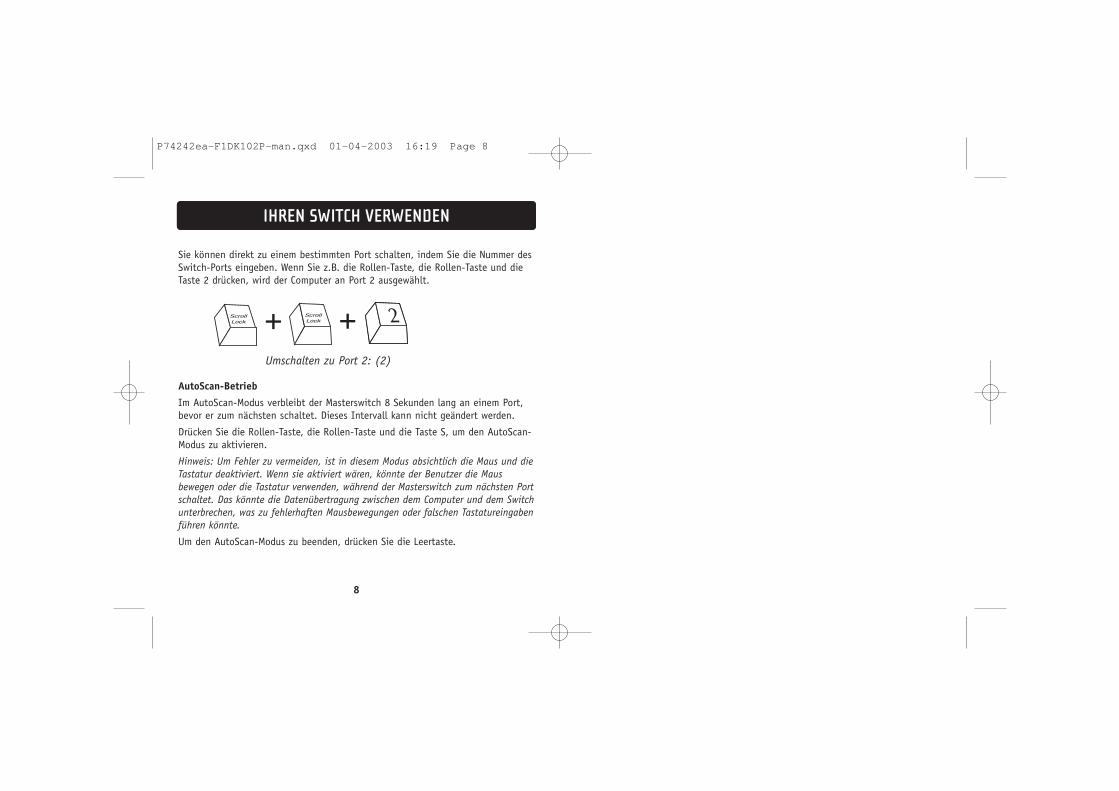
Sie können direkt zu einem bestimmten Port schalten, indem Sie die Nummer desSwitch-Ports eingeben. Wenn Sie z.B. die Rollen-Taste, die Rollen-Taste und dieTaste 2 drücken, wird der Computer an Port 2 ausgewählt.
AutoScan-Betrieb
Im AutoScan-Modus verbleibt der Masterswitch 8 Sekunden lang an einem Port,bevor er zum nächsten schaltet. Dieses Intervall kann nicht geändert werden.
Drücken Sie die Rollen-Taste, die Rollen-Taste und die Taste S, um den AutoScan-Modus zu aktivieren.
Hinweis: Um Fehler zu vermeiden, ist in diesem Modus absichtlich die Maus und dieTastatur deaktiviert. Wenn sie aktiviert wären, könnte der Benutzer die Mausbewegen oder die Tastatur verwenden, während der Masterswitch zum nächsten Portschaltet. Das könnte die Datenübertragung zwischen dem Computer und dem Switchunterbrechen, was zu fehlerhaften Mausbewegungen oder falschen Tastatureingabenführen könnte.
Um den AutoScan-Modus zu beenden, drücken Sie die Leertaste.
8
IHREN SWITCH VERWENDEN
+ +Umschalten zu Port 2: (2)
P74242ea-F1DK102P-man.qxd 01-04-2003 16:19 Page 8
OMNICUBE 2-poorts switchmet geïntegreerde kabels
HandleidingF1DK102P
Beheer twee computers met slechts één monitor, PS/2-toetsenbord en muis
Met een 2-poorts kvm-switch van Belkin met geïntegreerde kabels kunt u tweecomputers bedienen met één toetsenbord, monitor en muis. De switch ondersteuntPS/2-invoerapparaten (toetsenbord en muis), VGA, SVGA, XGA en PS/2-computers.
Overzicht productkenmerkenComplete, compacte oplossingMet ingebouwde kabels en gekleurde aansluitingen voor een optimaalgebruiksgemak.
SneltoetsenVia speciale sneltoetsen kiest u snel de gewenste poort. Bedien verschillendecomputers via eenvoudige sneltoetscombinaties op het toetsenbord.
AutoScan-functieDe AutoScan-functie scant automatisch de op de switch aangesloten computerséén voor één op activiteit.
Beeldresolutie De switch ondersteunt beeldresoluties tot 2048x1536 op 65 Hz. De switch isvoorzien van 75 ohm VGA-coaxkabels voor optimale signaaldoorgifte bij hogeresoluties.
LED-controlelampjes LED's boven op de switch geven de actuele toestand weer. De LED van de actievemonitorpoort licht op.
BesturingssystemenDe switch is geschikt voor computers met:Besturingssysteem• Windows® 95, 98, 2000, Me, NT®, XP• DOS• Linux® • Novell® NetWare® 4.x/5.x
Toetsenbord • Met 101, 102 of 104 toetsen
Muis • Microsoft®-compatibele PS/2-muis met 2, 3, 4 of 5 knoppen
Monitor • VGA• SVGA• MultiSync®
OVERZICHT
2
P74242ea-F1DK102P-man.qxd 01-04-2003 16:19 Page 2
Stap-voor-stap installeren
Dit hoofdstuk geeft een volledige beschrijving van het installeren van eenswitch.
Let op, belangrijk
Schakel alle apparaten uit voordat u iets probeert aan te sluiten op de switch ofop een computer. Het aansluiten en loshalen van kabels bij ingeschakeldecomputers kan uw computers, uw gegevens en/of de switch permanentbeschadigen. Belkin Corporation is niet aansprakelijk voor enige schade die opdie manier is ontstaan.
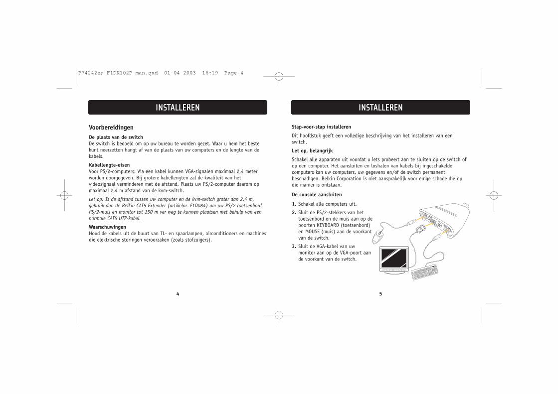
De console aansluiten
1. Schakel alle computers uit.
2. Sluit de PS/2-stekkers van hettoetsenbord en de muis aan op depoorten KEYBOARD (toetsenbord)en MOUSE (muis) aan de voorkantvan de switch.
3. Sluit de VGA-kabel van uw monitor aan op de VGA-poort aande voorkant van de switch.
INSTALLATIONINSTALLEREN
54
VoorbereidingenDe plaats van de switch De switch is bedoeld om op uw bureau te worden gezet. Waar u hem het bestekunt neerzetten hangt af van de plaats van uw computers en de lengte van dekabels.
Kabellengte-eisen Voor PS/2-computers: Via een kabel kunnen VGA-signalen maximaal 2,4 meterworden doorgegeven. Bij grotere kabellengten zal de kwaliteit van hetvideosignaal verminderen met de afstand. Plaats uw PS/2-computer daarom opmaximaal 2,4 m afstand van de kvm-switch.
Let op: Is de afstand tussen uw computer en de kvm-switch groter dan 2,4 m,gebruik dan de Belkin CAT5 Extender (artikelnr. F1D084) om uw PS/2-toetsenbord,PS/2-muis en monitor tot 150 m ver weg te kunnen plaatsen met behulp van eennormale CAT5 UTP-kabel.
Waarschuwingen Houd de kabels uit de buurt van TL- en spaarlampen, airconditioners en machinesdie elektrische storingen veroorzaken (zoals stofzuigers).
INSTALLEREN
P74242ea-F1DK102P-man.qxd 01-04-2003 16:19 Page 4
De computers inschakelen
Sluit eerst alle kabels aan, en schakel daarna pas de computers in die u op deswitch heeft aangesloten. U mag alle computers tegelijk inschakelen. De switchemuleert een muis en een toetsenbord voor elke poort, zodat alle computersnormaal zullen opstarten. De switch is nu klaar voor gebruik.
Via sneltoetscommando's kunt u selecteren welke computer u wilt bedienen. Houder rekening mee dat het gekozen beeld pas 1-2 seconden na het omschakelen opde monitor zal verschijnen. Dit komt door de verversingssnelheid van hetvideosignaal. Ook zullen de signalen van de muis en het toetsenbord opnieuwworden gesynchroniseerd. Dit is de normale procedure die zorgt voor eenprobleemloze omschakeling.
U kunt ook via het toetsenbord een andere switch-poort kiezen met eencombinatie van de “SCROLL LOCK”-toets en de pijltjestoetsen voor omhoog enomlaag. Stuur een commando naar de switch door binnen twee seconden tweekeer op de “SCROLL LOCK”-toets te drukken. Ter bevestiging hoort u een piepje.Vervolgens kunt u met de pijltjestoetsen voor omhoog en omlaag een anderepoort kiezen.
7
DE SWITCH GEBRUIKEN
Met 'pijltje omhoog' kiest u devolgende actieve poort
Met 'pijltje omlaag' kiest u devorige actieve poort
De computer aansluiten
1. Gebruik de geïntegreerde kabels en sluit de VGA-kabel aan op de VGA-poortvan de eerste computer.
2. Sluit de PS/2-toetsenbordkabel van de kvm-switch aan op detoetsenbordaansluiting van de computer.
3. Sluit de PS/2-muiskabel van de kvm-switch aan op de muispoort van decomputer.
Herhaal de stappen 1 t/m 3 voor de andere computer die u op de switch wiltaansluiten.
6
INSTALLEREN
P74242ea-F1DK102P-man.qxd 01-04-2003 16:19 Page 6
Of u kunt direct het gewenste poortnummer kiezen. Druk bijvoorbeeld op “SCROLLLOCK”, “SCROLL LOCK” en op “2” om de computer te selecteren die op poort 2 isaangesloten.
AutoScan-functie
Bij ingeschakelde AutoScan-functie activeert de switch acht seconden lang eenpoort, en schakelt dan om naar de volgende. U kunt deze periode niet zelfwijzigen.
U schakelt de AutoScan-functie in met “SCROLL LOCK”, “SCROLL LOCK” en “S”.
Let op: Als deze functie is ingeschakeld zullen de muis en het toetsenbord nietwerken, om fouten te voorkomen. Zouden ze wel zijn ingeschakeld, dan zou utijdens het omschakelen per ongeluk de muis kunnen verplaatsen of hettoetsenbord kunnen bedienen. Dit kan de communicatie tussen de computer en deswitch verstoren, wat vreemde cursorverplaatsingen of rare letters kan opleveren.
Druk op de spatiebalk om de AutoScan-functie uit te schakelen.
8
DE SWITCH GEBRUIKEN
+ +Omschakelen naar poort 2—(2)
P74242ea-F1DK102P-man.qxd 01-04-2003 16:19 Page 8
Manual de usuarioF1DK102P
Controla dos ordenadores utilizando un monitor de vídeo, un teclado PS/2 y un ratón
OMNICUBE Conmutador de 2 puertos con cableadoincorporado
El Conmutador KVM de 2 puertos de Belkin con cableado incorporado le permitecontrolar varios ordenadores con un teclado, monitor y ratón. El Conmutador admitedispositivos de entrada PS/2 (teclado y ratón), VGA, SVGA, XGA y ordenadores PS/2.
Características Descripción generalSolución compacta completa: Cables incorporados y conectores codificados mediante colores que facilitan elfuncionamiento y la organización.
Teclas de acceso rápido:Las teclas de acceso rápido le permiten seleccionar puertos utilizando comandos deteclas designados. Controla varios ordenadores utilizando una secuencia simple deteclas de acceso rápido en su teclado.
AutoScan:La característica AutoScan le permite explorar y monitorizar automáticamente lasactividades de todos los ordenadores en funcionamiento conectados a suConmutador uno a uno.
Resolución de vídeo:El Conmutador admite resoluciones de vídeo de hasta 2048x1536@65Hz. Parapreservar la integridad de la señal a altas resoluciones, se incorpora un cablecoaxial VGA de 75 Ohmios en su Conmutador.
Indicadores LED en la parte superior del Conmutador: Funcionan como monitores de estado. Los indicadores LED se iluminan paraindicar qué puerto del monitor correspondiente está actualmente activo.
Conmutador KVM de 2 puertos con cableado incorporado:
Consola Puerto de ratón
Diagrama de visualización del equipo
Cables incorporados
Consola Puerto de teclado
Consola Puerto del monitor VGA
Sistemas operativosSu Conmutador es para utilizar en CPU utilizando:Plataformas• Windows® 95, 98, 2000, Me, NT®, XP• DOS• Linux® • Novell® NetWare® 4.x/5.x
Teclados • Admite teclados de 101, 102 y 104 teclas
Ratón• Ratones PS/2 compatible con sistema Microsoft® con 2, 3, 4 o 5 botones
Monitores • VGA• SVGA• MultiSync®
DESCRIPCIÓN GENERAL
2
P74242ea-F1DK102P-man.qxd 01-04-2003 16:19 Page 2
Guía de instalación paso a paso
Esta sección le proporciona instrucciones completas para la configuración delhardware de un único Conmutador.
Nota importante
Antes de conectar ningún dispositivo al Conmutador o a cualquiera de losordenadores, asegúrese de que todos los dispositivos estén apagados. Laconexión y desconexión de cables con los ordenadores encendidos podría producirdaños irreversibles en los ordenadores, datos y/o el Conmutador. BelkinCorporation no se hace responsable de los daños causados de esta forma.
Conexión de la consola
1. Apague todos los ordenadores.
2. Conecte su teclado tipo PS/2 y elratón en los puertos del TECLADO yel RATÓN localizados en el panelfrontal del Conmutador.
3. Tome el cable VGA que tieneconectado al monitor y conécteloal puerto VGA del panel frontal delConmutador.
INSTALLATIONINSTALACIÓN
54
Pre-configuraciónDonde colocar el ConmutadorEl Conmutador está diseñado para colocare en un PC de sobremesa. El lugarexacto se basará en la ubicación de su CPU y la longitud de sus cables.
Requisitos de distancia del cable Para ordenadores PS/2: Las señales VGA se pueden transmitir correctamente a unadistancia de hasta 8 pies (2 metros y medio). Más allá de los ocho pies,probablemente disminuya la calidad de la señal de vídeo al aumentar ladistancia. Por esta razón, el ordenador con puerto PS/2 debe colocarse a menosde ocho pies de distancia del Conmutador KVM.
Nota: Si su ordenador debe instalarse a más de ocho pies de distancia delConmutador KVM podrá utilizar el prolongador Belkin CAT5 (número de piezaF1D084) para prolongar su teclado PS/2, ratón PS/2 y monitor hasta una distanciade 500 pies (152,4m) utilizando cable UTP CAT5 estándar.
Precauciones y Advertencias Evite colocar los cables cerca de tubos fluorescentes, equipos de aireacondicionado o máquinas que generen ruido eléctrico (por ejemplo:aspiradores).
INSTALACIÓN
P74242ea-F1DK102P-man.qxd 01-04-2003 16:19 Page 4
Encendido de los sistemas
Una vez que todos los cables han sido conectados, encienda la CPU que estáconectada al Conmutador. Se pueden encender de forma simultánea todos losordenadores. El Conmutador emula un ratón y un teclado en cada puerto ypermitirá a su ordenador arrancar normalmente. Ahora estará listo su Conmutadorpara ser utilizado.
Puede seleccionar qué ordenador funcionará mediante comandos de teclasrápidas. Observe que la señal de vídeo tardará entre 1 y 2 segundos en aparecerdespués de la conmutación. Esto se debe al refresco de la señal de vídeo.También se lleva a cabo una resincronización de las señales del ratón y teclado.Esta es una operación normal y garantiza que se establezca la sincronizaciónadecuada.
Podrá cambiar de forma conveniente los puertos del Conmutador mediante unasecuencia de comandos de teclado utilizando las teclas “BLOQUEODESPLAZAMIENTO” y las teclas de cursor arriba y abajo. Para enviar los comandosal Conmutador, pulse la tecla “BLOQUEO DESPLAZAMIENTO” dos veces en menosde dos segundos. Oirá un “bip” indicando la confirmación. A continuación podrápulsar las teclas de cursor arriba y abajo para cambiar entre los distintos puertos.
7
UTILIZANDO SU CONMUTADOR
Conmutar al puerto activosiguiente, cursor arriba
Conmutar al puerto activo anterior, cursor abajo
Conexión del ordenador
1. Utilizando los cables conectados, tome el cable VGA y conéctelo al puerto VGAdel primer ordenador.
2. Conecte el cable KVM del teclado PS/2 en el puerto del teclado del ordenador.
3. Conecte el cable KVM del ratón PS/2 en el puerto del ratón del ordenador.
Repita los pasos 1 a 3 para el ordenador adicional que se conecte al Conmutador.
6
INSTALACIÓN
P74242ea-F1DK102P-man.qxd 01-04-2003 16:19 Page 6
Podrá conmutar directamente a cualquier puerto introduciendo el número depuerto del Conmutador que desee utilizar. Por ejemplo, si pulsa “BLOQUEODESPLAZAMIENTO”, “BLOQUEO DESPLAZAMIENTO”, “2”, se seleccionará elordenador conectado al puerto 2.
Modo AutoScan
En el modo AutoScan el Conmutador permanece en un puerto durante ochosegundos antes de cambiar al siguiente. Este intervalo de tiempo no puedecambiarse.
Para activar el modo AutoScan, pulse “BLOQUEO DESPLAZAMIENTO”, “BLOQUEODESPLAZAMIENTO”, “S”.
Nota: No hay control de ratón ni teclado en este modo por diseño, para evitarerrores. Si estuviera activado, el usuario podría mover el ratón o utilizar el tecladomientras el Conmutador KVM está conmutando al puerto siguiente. Esto podríainterrumpir la comunicación entre el ordenador y el Conmutador, lo que podríaproducir movimientos erráticos del ratón o dar como resultado una visualizaciónerrática de los caracteres cuando se utiliza el teclado.
Para desactivar el modo AutoScan, pulse la barra espaciadora.
8
UTILIZANDO SU CONMUTADOR
+ +Conmutador al Puerto 2—(2)
P74242ea-F1DK102P-man.qxd 01-04-2003 16:19 Page 8
Switch a 2 portie OMNICUBEcon cablaggio incorporato
Manuale dell’utenteF1DK102P
Per permettere di utilizzare due computer mediante un singolo monitor, tastiera PS/2 e mouse
Lo switch KVM a 2 porte Belkin con cablaggio incorporato permette il controllo dicomputer multipli mediante un singolo insieme composto da tastiera, monitor emouse. Lo switch supporta dispositivi di entrata PS/2 (tastiera e mouse), nonchécomputer di tipo VGA, SVGA, XGA e PS/2.
Panoramica delle caratteristicheSoluzioni complete e compatte: come cablaggi incorporati e connettori a colori codificati rendono facili le operazioni e l’organizzazione.
Combinazioni rapide di tasti:permettono la selezione di porti mediante predefinizioni di tasti da battere.Controllo di computer multipli mediante una semplice sequenza di tasti battuti sulla tastiera.
AutoScan:questa caratteristica consente la scansione automatica e il monitoraggio delleattività di tutti i computer operativi collegati allo switch, ad uno ad uno.
Risoluzione video:lo switch è in grado di supportare risoluzioni video fino a 2048x1536 a 65 Hz.Per preservare l’integrità del segnale alle alte risoluzioni, nello switch èincorporato un cablaggio VGA a 75 Ohm.
Visualizzazione a diodi elettroluminescanti:i LED sullo switch indicano il monitoraggio dello stato. I LED si accendono perindicare il porto corrispondente di monitoraggio correntemente attivo.
Lo switch KVM a 2 porte con cablaggio incorporato:
Console: porto del mouse
Diagramma di visualizzazione dell’unità
Cavi incorporati
Console: porto della tastiera
Console: porti per monitor VGA
Sistemi operativi Lo switch è previsto per un’utilizzazione con i seguenti computer:Piattaforme • Windows® 95, 98, 2000, Me, NT® e XP• DOS• Linux® • Novell® NetWare® 4.x/5.x
Tastiere • Per tipi a 101, 102 e 104 tasti
Mouse • Per mouse di tipo PS/2 compatibile Microsoft®, a 2, 3, 4 o 5 pulsanti
Monitor • VGA• SVGA• MultiSync®
PANORAMICA
2
P74242ea-F1DK102P-man.qxd 01-04-2003 16:19 Page 2
Guida d’installazione passo a passo
Questo paragrafo fornisce istruzioni complete per l’installazione materiale di unsingolo switch.
Avviso importante
Prima di tentare di collegare delle unità allo switch o a qualsiasi altro computer,assicurarsi che tutti i dispositivi siano spenti. Il fatto di collegare edisconnettere cavi mentre i computer sono accesi può provocare danniirreparabili ai computer, ai dati e/o allo switch. La Belkin Corporation non potràessere ritenuta responsabile di alcun danno insorto in questo modo.
Collegamento della console
1. Spegnere tutti i computer.
2. Collegare la tastiera e il mouse,ambedue di tipo PS/2, ai portiindicati rispettivamente conKEYBOARD e MOUSE e che sitrovano sul pannello frontale dello switch.
3. Collegare il cavo video VGA cheproviene dal monitor al porto VGAche si trova sul pannello frontaledello switch.
5
INSTALLATIONINSTALLAZIONE
4
PreconfigurazioneDove posizionare lo switch: lo switch è previsto per essere sistemato sulla scrivania. La sua sistemazioneesatta sarà determinata dalla posizione del computer e dalla lunghezza dei cavi.
Requisiti di lunghezza dei cavi per computer di tipo PS/2: i segnali VGA sono ricevuti meglio se la lunghezza del cavo non supera i due metri e mezzo. Oltre i due metri e mezzo, la possibilitàdi degrado del segnale video aumenta con l’incremento della distanza da coprire.Per questo motivo, il computer di tipo PS/2 dovrebbe essere sistemato a non piùdi due metri e mezzo di distanza dallo switch KVM.
Nota: Nel caso che il computer deva essere sistemato a più di due metri e mezzodallo switch KVM, si può impiegare il cavo d’estensione Belkin CAT5 (numero diarticolo F1D084) per prolungare il collegamento della tastiera PS/2, del mousePS/2 e del monitor fino a 152,4 metri (500 piedi) di distanza, per mezzo di uncavo standard UTP CAT5.
Precauzioni e avvertimenti: evitare di sistemare cavi accanto a luci fluorescenti (neon), di apparecchiature di aria condizionata o di macchinari che producono interferenze elettriche (come ad esempio aspirapolvere).
INSTALLAZIONE
P74242ea-F1DK102P-man.qxd 01-04-2003 16:19 Page 4
Accensione dei sistemi
Una volta collegati tutti i cavi, accendere i computer connessi allo switch. Tutti i computer possono essere accesi contemporaneamente. Lo switchsimula un mouse e una tastiera per ciasun porto e consentirà al computerun’inizializzazione normale. Lo switch è ora pronto ad essere utilizzato.
Si può selezionare il computer da operare tramite combinazioni di tastiappropriate. Da notare che saranno necessari 1 o 2 secondi per la visualizzazioneallo schermo dopo la commutazione. Ciò è dovuto all’aggiornamento del segnalevideo. Viene compiuta inoltre una risincronizzazione dei segnali del mouse e dellatastiera. Si tratta di un’operazione normale che assicura che venga stabilita unasincronizzazione appropriata.
Si possono cambiare a piacere i porti dello switch tramite una sequenza dicomandi dalla tastiera, servendosi del tasto "Scroll Lock" (blocco delloscorrimento) e dei tasti con le frecce verso l'alto e il basso. Per inoltrare comandiverso lo switch, premere il tasto “Scroll Lock” per due volte in un intervallo didue secondi. Si sentirà un segnale sonoro di conferma. A questo punto si potràpremere il tasto con la freccia verso l’alto o il basso per commutare tra i variporte.
7
UTILIZZAZIONE DELLO SWITCH
Per commutare verso il porto attivosuccessivo, premere sul tasto con lafreccia verso l’alto.
Per commutare verso il porto attivoprecedente, premere sul tasto con lafreccia verso il basso.
Collegamento del computer
1. Impiegando i cavi già collegati, connettere il cavo VGA alla porta VGA del primo computer.
2. Collegare il cavo KVM della tastiera PS/2 alla porta della tastiera del computer.
3. Collegare il cavo KVM del mouse PS/2 alla porta del mouse del computer.
Ripetere i passi dall’1 al 3 per altri computer che devano essere collegati alloswitch.
6
INSTALLAZIONE
P74242ea-F1DK102P-man.qxd 01-04-2003 16:19 Page 6
Si può commutare direttamente un qualsiasi porto immettendo il numero di portodello switch che si desidera utilizzare. Ad esempio, se si preme “Scroll Lock”,“Scroll Lock” e “2”, viene selezionato il computer colleagto al porto 2.
Modo di auto-scansione
In modo auto-scansione, lo switch resta su un dato porto per otto secondi primadi commutare verso il successivo. Questo intervallo di tempo non può esseremodificato.
Per abilitare il modo AutoScan, premere “Scroll Lock”, “Scroll Lock” ed “S”.
Nota: in questa modalità non sono volutamente presenti controlli del mouse o dellatastiera, al fine di prevenire eventuali errori. Infatti, se tali controlli fosseroabilitati, l’utente potrebbe spostare il mouse o la tastiera mentre lo switch KVM stacommutando verso il porto successivo. Questo fatto potrebbe interrompere lacomunicazione tra il computer e lo switch causando un movimento imprevedibiledel mouse, o una strana visualizzazione di caratteri durante l’utilizzo della tastiera.
Per disabilitare il modo Auto-Scan, premere la barra di spaziatura.