+ All Categories
Home > Documents > Concept and Requirements for Airport Surface Conflict ... · Concept and Requirements for Airport...

Concept and Requirements for Airport Surface Conflict ... · Concept and Requirements for Airport...

Date post: 10-May-2018
Category:
Upload: doantuong
View: 216 times
Download: 0 times
Share this document with a friend
25
Concept and Requirements for Airport Surface Conflict Detection and Resolution Sai Vaddi 1 , Gregory D. Sweriduk 2 , Jason Kwan 3 , Vivian Lin 4 , Jimmy Nguyen 5 , and Victor H. L. Cheng 6 Optimal Synthesis Inc., Los Altos, CA, 94022 The paper deals with the concept and requirement for airport surface Conflict Detection and Resolution (CD&R). The scope of the proposed CD&R concept spans across three different timeframes: (i) near-term (2015), (ii) mid-term (2020), and (iii) far-term (2025). Enabling technologies such as (i) surveillance, (ii) airport surface operations planning automation, (iii) clearance delivery mechanism, (iv) clearance information available to CD&R automation, and (v) flight-deck automation are studied. The paper identifies the functional requirements for the CD&R automation system such as aircraft state estimation module and aircraft trajectory prediction module. Detalied descriptions of the individual algorithms are beyond the scope of the current paper and will be presented in a future paper. However, preliminary closed-loop simulation results obtained with the conflict detection and resolution system are presented. I. Introduction urrent-day operations require the Air Navigation Service Provider (ANSP) to specify the taxi routes, control the order of merging at intersections, sequence runway crossings and departures at the runways, and require the pilots to provide separation visually. To enhance situational awareness of the ANSP, the FAA is introducing new surface surveillance technologies such as Airport Surface Detection Equipment Model X (ASDE-X) 1 and Automatic Dependent Surveillance Broadcast (ADS-B) 2 , which provide aircraft position data in all-weather situations and support the prediction of future aircraft trajectories more accurately than before. Other technologies useful for conflict and incursion detection or prevention include the Airport Movement Area Safety System (AMASS) 3,4 and Runway Status Lights 5 . Previous NASA research for improving situational awareness on the flight deck include the Taxiway Navigation and Situation Awareness (T-NASA) System 6,7 developed at NASA Ames Research Center, and the Runway Incursion Prevention System (RIPS) 8,9 developed at NASA Langley Research Center. Researchers at NASA Langley are also building on the earlier RIPS technologies to develop flight-deck technologies for collision avoidance 10 referred to as Collision Avoidance for Airport Traffic (CAAT). The Runway Incursion Alerting System (RIAS) 11 consisting of millimeter-wave radar and pan/tilt/zoom cameras was developed by QinetiQ. The Surface Management System (SMS) 12 , developed by NASA in cooperation with the FAA, is a valuable decision-support tool for service providers and users of the National Airspace System (NAS) for providing situational awareness of the airport traffic 13 . Researchers from Mosaic ATM used the route generation capability of the Surface Decision Support System (SDSS)the SMS testbed fielded by the FAAto study the feasibility of a conformance monitoring function 14 . Mosaic ATM is currently investigating surface trajectory prediction and taxi conformance monitoring under a NASA Research Announcement (NRA) award 15 . The EUROCONTROL Advanced Surface Movement Guidance and Control System (A-SMGCS) 16 concept includes research on optimization of airport taxi scheduling 17 . A-SMGCS Level 2 consists of automated monitoring and alerting functions, and includes the prediction of conflicts on active runways or incursions into restricted areas. 1 Research Scientist, 95 First Street, Ste 240, AIAA Member. 2 Research Scientist, 95 First Street, Ste 240, AIAA Senior Member. 3 Research Enginner, 95 First Street, Ste 240. 4 Research Engineer, 95 First Street, Ste 240. 5 Research Engineer, 95 First Street, Ste 240. 6 Vice President, 95 First Street, Ste 240, AIAA Associate Fellow. C 11th AIAA Aviation Technology, Integration, and Operations (ATIO) Conference, including the AIA 20 - 22 September 2011, Virginia Beach, VA AIAA 2011-7050 Copyright © 2011 by Optimal Synthesis Inc, 2011. Published by the American Institute of Aeronautics and Astronautics, Inc., with permission. Downloaded by UNIVERSITY OF CALIFORNIA - BERKELEY on June 25, 2014 | http://arc.aiaa.org | DOI: 10.2514/6.2011-7050
Transcript

Concept and Requirements for Airport Surface Conflict

Detection and Resolution

Sai Vaddi1, Gregory D. Sweriduk

2, Jason Kwan

3, Vivian Lin

4, Jimmy Nguyen

5, and Victor H. L. Cheng

6

Optimal Synthesis Inc., Los Altos, CA, 94022

The paper deals with the concept and requirement for airport surface Conflict Detection

and Resolution (CD&R). The scope of the proposed CD&R concept spans across three

different timeframes: (i) near-term (2015), (ii) mid-term (2020), and (iii) far-term (2025).

Enabling technologies such as (i) surveillance, (ii) airport surface operations planning

automation, (iii) clearance delivery mechanism, (iv) clearance information available to

CD&R automation, and (v) flight-deck automation are studied. The paper identifies the

functional requirements for the CD&R automation system such as aircraft state estimation

module and aircraft trajectory prediction module. Detalied descriptions of the individual

algorithms are beyond the scope of the current paper and will be presented in a future

paper. However, preliminary closed-loop simulation results obtained with the conflict

detection and resolution system are presented.

I. Introduction

urrent-day operations require the Air Navigation Service Provider (ANSP) to specify the taxi routes, control the

order of merging at intersections, sequence runway crossings and departures at the runways, and require the

pilots to provide separation visually. To enhance situational awareness of the ANSP, the FAA is introducing new

surface surveillance technologies such as Airport Surface Detection Equipment – Model X (ASDE-X)1 and

Automatic Dependent Surveillance – Broadcast (ADS-B)2, which provide aircraft position data in all-weather

situations and support the prediction of future aircraft trajectories more accurately than before. Other technologies

useful for conflict and incursion detection or prevention include the Airport Movement Area Safety System

(AMASS)3,4

and Runway Status Lights5. Previous NASA research for improving situational awareness on the flight

deck include the Taxiway Navigation and Situation Awareness (T-NASA) System6,7

developed at NASA Ames

Research Center, and the Runway Incursion Prevention System (RIPS) 8,9

developed at NASA Langley Research

Center. Researchers at NASA Langley are also building on the earlier RIPS technologies to develop flight-deck

technologies for collision avoidance10

referred to as Collision Avoidance for Airport Traffic (CAAT). The Runway

Incursion Alerting System (RIAS)11

consisting of millimeter-wave radar and pan/tilt/zoom cameras was developed

by QinetiQ.

The Surface Management System (SMS)12

, developed by NASA in cooperation with the FAA, is a valuable

decision-support tool for service providers and users of the National Airspace System (NAS) for providing

situational awareness of the airport traffic 13

. Researchers from Mosaic ATM used the route generation capability of

the Surface Decision Support System (SDSS)—the SMS testbed fielded by the FAA—to study the feasibility of a

conformance monitoring function14

. Mosaic ATM is currently investigating surface trajectory prediction and taxi

conformance monitoring under a NASA Research Announcement (NRA) award15

.

The EUROCONTROL Advanced Surface Movement Guidance and Control System (A-SMGCS)16

concept

includes research on optimization of airport taxi scheduling17

. A-SMGCS Level 2 consists of automated monitoring

and alerting functions, and includes the prediction of conflicts on active runways or incursions into restricted areas.

1 Research Scientist, 95 First Street, Ste 240, AIAA Member.

2 Research Scientist, 95 First Street, Ste 240, AIAA Senior Member.

3 Research Enginner, 95 First Street, Ste 240.

4 Research Engineer, 95 First Street, Ste 240.

5 Research Engineer, 95 First Street, Ste 240.

6 Vice President, 95 First Street, Ste 240, AIAA Associate Fellow.

C

11th AIAA Aviation Technology, Integration, and Operations (ATIO) Conference, including the AIA20 - 22 September 2011, Virginia Beach, VA

AIAA 2011-7050

Copyright © 2011 by Optimal Synthesis Inc, 2011. Published by the American Institute of Aeronautics and Astronautics, Inc., with permission.

Dow

nloa

ded

by U

NIV

ER

SIT

Y O

F C

AL

IFO

RN

IA -

BE

RK

EL

EY

on

June

25,

201

4 | h

ttp://

arc.

aiaa

.org

| D

OI:

10.

2514

/6.2

011-

7050

The European Airport Movement Management by A-SMGCS (EMMA) project defined A-SMGCS operational

requirements18

for the ANSP and flight deck, and other important services (e.g., communication, navigation, and

surveillance (CNS)19

). Further development of A-SMGCS services, procedures, and operational requirements has

been documented as part of the EMMA2 effort20

.

II. CD&R Automation System

The primary objective of the proposed research is to study the concepts and requirements for a CD&R automation

system that is suitable for current-day operations as well as futuristic 4D-trajectory operations envisioned for the

Next-Generation Air Trasportation System (NextGen). Other systems such as the SMS, AMASS and ASDE-X were

not designed for 4D-trajectory operations. Moreover, although these systems have the ability to alert controllers of

conflicts resulting from safety violations, they do not seem to have any conflict resolution capability. Surface

Operation Automation Research (SOAR)21–25

, the seminal research in surface 4D-trajectory operations pioneered by

Optimal Synthesis Inc (OSI), takes a holistic approach to the problem. During SOAR, OSI developed collaborative

automation systems for the tower as well as for the flight deck to enable 4D-trajectory operations. The SOAR

concept examined the surface traffic control problem as an integrated system involving the ANSP, the flight deck,

and their associated automation systems and other enabling technologies. The planner envisioned under the SOAR

concept not only assigns taxiways and runways but also computes a Required Time of Arrival (RTA) at select nodes

along the taxiways and the runways. The planner schedules the flights with tighter inter-aircraft time separation at

nodes under the assumption that the flights can realize these RTAs using flight-deck automation technologies such

as Flight Deck Automation for Reliable Ground Operations (FARGO)26–28

. Whereas the tight inter-aircraft time

separation leads to increased efficiency and throughput, the tighter operational margins make the system more prone

to multiple conflicts even if one flight underperforms and does not adhere to its RTAs. Such conflicts will require

replanning of all the flights that are affected by the conflicts.

The following are the objectives of the airport surface CD&R automation system:

Enhance situational awareness of tower controllers by continually monitoring the airport surface traffic and

predicting conflicts on taxiways and runways.

Take into account the intent information of the aircraft resulting from airport surface operations planning to

predict conflicts.

Detect and alert tower controllers of conflicts over two different time horizons: (i) short-term, and (ii) long-

term. These time horizons are different from the operational timeframes defined in the Abstract and in the

Scope section below. These time horizons define time segments pertinent to the arrival and departure

flights.

Short-term conflicts are impending conflicts and are expected to occur in a time horizon that is

comparable to the time it takes to communicate to the pilot plus the time it takes an aircraft to

come to a complete stop. The time horizon for short-term conflicts could be less than 30 s.

Long-term conflicts are relevant in the context of mid-term and far-term operations where the

intent of the aircraft is known. In the case of mid-term operations, the scheduled ramp spot release

time, assigned taxi route of the aircraft, and the scheduled departure time of the aircraft form the

intent of the aircraft. In the case of far-term operations, the complete 4D route of the aircraft

described in terms of a node sequence with a time of crossing for each node form the intent of the

aircraft. Intent of the aircraft facilitates longer term trajectory prediction and thereby long-term

conflict detection.

Assist controllers in resolving conflicts in an efficient manner:

Generate route, sequence, start time, and speed advisories for resolving conflicts.

Generate options for replanning in response to long-term conflicts.

A. Scope

The physical scope of the proposed CD&R system comprises the following:

Departure Aircraft: Starting from the ramp spot, followed by taxiways, runway crossing, and takeoff roll to

takeoff.

Arrival Aircraft: Starting from the moment they are cleared for landing, or when they cross the outer

marker, or when they are first registered on the ground-based surveillance system, through flare,

touchdown, and rollout, followed by runway exits and runway crossings, through taxiways to the ramp

spot.

Dow

nloa

ded

by U

NIV

ER

SIT

Y O

F C

AL

IFO

RN

IA -

BE

RK

EL

EY

on

June

25,

201

4 | h

ttp://

arc.

aiaa

.org

| D

OI:

10.

2514

/6.2

011-

7050

The scope of the system also extends across different technological and operational timeframes recognized as (i)

Near-Term (2015), (ii) Mid-Term (2020), and (iii) Far-Term (2025 and beyond).

Near-Term: An operational timeframe where the operations and technology are reflective of current-day

operations and capabilities. The phrases ―near-term‖ and ―current-day‖ are used interchangeably in this

paper.

Far-term: An operational timeframe where the operational concepts are based on NextGen 4D-trajectory

operations. Again, the phrases ―far-term‖ and ―4D-trajectory operations‖ are used to describe operations in

the same timeframe in this paper.

Mid-term: A transitional timeframe between the near-term and far-term timeframes where the operations

are the same as current-day, but technological improvements in surveillance and automation systems are

expected.

The scope of the system in terms of the personnel expected to interact with the automation includes the

following:

Ground controllers for arrival and departure flights

Local controllers for arrival and departure flights

Flight crew on the flight decks (i.e., pilots and first officers)

B. Airport Surface Conflicts

A conflict in the en route airspace is defined based on separation requirements of 5 NM inter-aircraft separation

in the horizontal plane or 1000 ft inter-aircraft separation in altitude. Unfortunately, no such simple definition of a

conflict exists for surface operations. At the simplest level, a conflict can be defined as a violation of safe inter-

aircraft separation. There are no standards for separation regarding taxiing aircraft; safe distances are left to the

judgment of the pilot. There are recommendations for safe distances behind an aircraft that relate to jet blast and

foreign object damage if the aircraft has to increase its throttles above idle, which may happen if the aircraft has

stopped and would resume movement.

1. Taxiway Conflicts

When there is crossing traffic, such as at intersections between two taxiways, a taxiway and a runway, or two

runways, there are prescribed distances that an aircraft must stay behind in order to insure being clear of crossing

traffic. These are illustrated in Figure 1; distances are given in Table 1 and Table 2. These distances are not strictly

enforced on taxiway intersections, though, and a flight may be cleared to proceed even though the crossing traffic

may not have completely cleared the intersection. Such clearances are issued with the proviso that it is left to the

pilot’s discretion that there is adequate separation, which has in some cases resulted in a collision.

Hold Line Centerline

Figure 1. Intersection Hold Distance

Dow

nloa

ded

by U

NIV

ER

SIT

Y O

F C

AL

IFO

RN

IA -

BE

RK

EL

EY

on

June

25,

201

4 | h

ttp://

arc.

aiaa

.org

| D

OI:

10.

2514

/6.2

011-

7050

Table 1. Holding Position Markings for Taxiway-Taxiway Intersections 29

Design Group

I II III IV V VI

Hold Distance

44.5 ft (13.5 m)

65.5 ft (20 m)

93 ft (28.5 m)

129.5 ft (39 m)

160 ft (48.5 m)

193 ft (59 m)

Table 2. Holding Position Markings for Runway-Runway/Taxiway Intersections 30

Aircraft Approach Category

Airplane Design Group

Visual and Nonprecision

Instrument

Precision Instrument

A & B

I, II 125 ft (38 m) 175 ft (53 m)

III 200 ft (60 m) 250 ft (75 m)

IV 250 ft (75 m) 250 ft (75 m)

C & D

I – IV 250 ft (75 m) 250 ft (75 m)

V 250 ft (75 m) 280 ft (85 m)

VI 250 ft (75 m) 280 ft (85 m)

Table 3. Aircraft Design Group Definitions

Design Group I II III IV V VI

Wingspan

(feet)

min (≥) – 49.0 79.0 118.0 171.0 214.0

max (<) 49.0 79.0 118.0 171.0 214.0 264.0

Table 4. Aircraft Approach Category Definitions

Approach Category A B C D E

VREF

(knots)

min (≥) – 91 121 141 166

max (<) 91 121 141 166 –

2. Runway Incursions

FAA defines runway incursion as any occurrence at an aerodrome involving the incorrect presence of an aircraft,

vehicle, or person on the protected area of a surface designated for the landing and take-off of aircraft . An incursion

may occur either because an aircraft or ground vehicle did not have the proper clearance, or because the controller

made an error when issuing a clearance. If an aircraft has been cleared to land on or take off from a runway, then all

other aircraft and ground vehicles must be clear of that runway; i.e. they must observe the hold lines (see Figure 2).

Otherwise, a runway incursion has occurred (in the example of Figure 2, Aircraft 2 has crossed the hold-short line

when Aircraft 1 is already cleared to land on the runway). The aircraft that is cleared to use that runway does not

have to be on the ground or have started its takeoff roll for there to be an incursion.

Dow

nloa

ded

by U

NIV

ER

SIT

Y O

F C

AL

IFO

RN

IA -

BE

RK

EL

EY

on

June

25,

201

4 | h

ttp://

arc.

aiaa

.org

| D

OI:

10.

2514

/6.2

011-

7050

Figure 2. Runway Incursion Example [ICAO]

A runway incursion also occurs if two flights have been cleared to use two intersecting runways simultaneously

(see Figure 3). Even though neither flight has improperly crossed a hold line, there is a significant possibility of a

loss of separation leading to a collision. Another example of an incursion is when an aircraft mistakenly lands on or

takes off from a runway for which it was not given a clearance. In each case a conflict can be detected based on

trajectory predictions and intent inference, but it may not be possible to discriminate who is at fault without

knowledge of the actual clearances.

Figure 3. Intersecting Runway Incursion Example

The FAA uses three primary metrics to assess runway incursions: the frequency of runway incursions, the

severity of runway incursions, and the types of runway incursions. Table 5 lists the categories of runway incursions.

Table 5. Severity Categories of Runway Incursions

Category Definition

A Separation decreases and participants take extreme action to narrowly avoid a collision, or the event results in a collision

B Separation decreases and there is a significant potential for collision

C Separation decreases but there is ample time and distance to avoid a potential collision

D Little or no chance of collision but meets the definition of a runway incursion

3. Wake Vortex Separation Violation

Every aircraft generates a wake while in flight. Initially, when pilots encountered this wake in flight, the

disturbance was attributed to ―prop wash.‖ It is known, however, that this disturbance is caused by a pair of counter-

rotating vortices trailing from the wing tips. Vortex strength generally increases with aircraft size, so the vortices

from larger aircraft pose problems to aircraft crossing behind or following that may encounter the wake. For

instance, the wake of these aircraft can impose rolling moments exceeding the roll-control authority of the

Dow

nloa

ded

by U

NIV

ER

SIT

Y O

F C

AL

IFO

RN

IA -

BE

RK

EL

EY

on

June

25,

201

4 | h

ttp://

arc.

aiaa

.org

| D

OI:

10.

2514

/6.2

011-

7050

encountering aircraft. A wake encounter can be catastrophic: in 1972 at Fort Worth a DC-9 got too close to a DC-10

(two miles back), rolled, caught a wingtip, and cartwheeled, coming to rest in an inverted position on the runway.

All aboard were killed. Serious and even fatal General Aviation (GA) accidents induced by wake vortices are not

uncommon.

The following are the FAA mandates for wake-vortex avoidance31

:

1. Separation is applied to aircraft operating directly behind a heavy/B757 jet at the same altitude or less than

1,000 feet below:

(a) Heavy jet behind heavy jet: 4 NM.

(b) Large/heavy behind B757: 4 NM.

(c) Small behind B757: 5 NM.

(d) Small/large aircraft behind heavy jet: 5 NM.

2. Also, separation, measured at the time the preceding aircraft is over the landing threshold, is provided to

small aircraft:

(a) Small aircraft landing behind heavy jet: 6 NM.

(b) Small aircraft landing behind B757: 5 NM.

(c) Small aircraft landing behind large aircraft: 4 NM.

3. Additionally, appropriate time or distance intervals are provided to departing aircraft:

(a) Two minutes or the appropriate 4 or 5-NM radar separation when taking off behind a

heavy/B757jet will be:

(1) From the same threshold.

(2) On a crossing runway and projected flight paths will cross.

(3) From the threshold of a parallel runway when staggered ahead of that of the adjacent runway

by less than 500 feet and when the runways are separated by less than 2,500 feet.

(b) A 3-minute interval will be provided when a small aircraft will takeoff:

(1) From an intersection on the same runway (same or opposite direction) behind a departing

large aircraft.

(2) In the opposite direction on the same runway behind a large aircraft takeoff or low/missed

approach.

C. CD&R System Concepts

Figure 4 is a closed-loop description of the airport surface operation dynamics with the CD&R system. It shows

the functional relationship of the proposed CD&R automation system with respect to the user (ATC), other surface

automation systems and physical systems such as aircraft and surveillance systems. The CD&R module is expected

to interact with two other automation systems: (i) an airport surface operations planner, and (ii) a conformance

monitoring module. These two types of automation systems are themselves currently being developed and are not

expected to be ready for the near-term timeframe. The CD&R automation system concept, however, is designed to

to both work both with and without them.

Input-output depictions of the CD&R system are shown in Figure 5, Figure 6, and Figure 7 for the near-term,

mid-term, and far-term timeframes respectively. Detailed description of the inputs and outputs is provided in the

following sections. The differences in the inputs and outputs are a result of different enabling technologies in each of

the three timeframes. An elaborate discussion of the enabling technologies is presented in Section III. The CD&R

module is primarily driven by surveillance data which characterize the state of the traffic on the airport surface. The

Planner, which is expected to be in place in the mid-term and far-term timeframes, is expected to provide the

additional input that characterizes the intent of the different aircraft. In the absence of a planner, the tower controller

(ATC) would issue tactical route clearances. Another module is the conformance-monitoring module that generates

Non-Conformance Alerts (NC Alerts) for those aircraft that are deviating from the agreed-upon clearance. Speech

recognition technology is observed as a possible candidate for transcribing voice-based clearances into a form

suitable for CD&R automation. It is shown in dotted lines because at the moment it is recognized as a possibility.

OSI is not aware of any deployment plans for such technology. Datalink capability between the tower and flight-

deck is expected for the mid-term operations. Therefore, the possibility of transmitting conflict-alert messages

directly to the flight-deck is recognized by the dotted line in Figure 6.

Dow

nloa

ded

by U

NIV

ER

SIT

Y O

F C

AL

IFO

RN

IA -

BE

RK

EL

EY

on

June

25,

201

4 | h

ttp://

arc.

aiaa

.org

| D

OI:

10.

2514

/6.2

011-

7050

Planner

CD&R

Conformance

Monitoring

ATC

Surveillance

System

AC1 Closed-

Loop Dynamics

.

.

.

AC2 Closed-

Loop Dynamics

ACN Closed-

Loop

Dynamics

Airport Surface

Traffic Dynamics

Actual AC StatesClearances

Surveillance

Measurements

NC

Ale

rts

Route, Sequence,

Schedule

Conflict Alerts

Conflict Resolutions

Flig

ht

Pla

n D

ata

NC

Ale

rts

Figure 4. Closed-Loop Depiction of the Airport Surface Operation Dynamics

CD&R ModuleSurveillance

System

ATC

Controller

Display

Flight Deck

Flight Plan

Database

Airport Layout &

Configuration

Database

AC Performance

Characteristics

Database

Conflict Alert

Messages

Conflict Resolution

Messages

Surveillance

Measurements

Voice Based

Clearances

Figure 5. Inputs and Outputs of the CD&R Automation System for Current-Day Operations

Dow

nloa

ded

by U

NIV

ER

SIT

Y O

F C

AL

IFO

RN

IA -

BE

RK

EL

EY

on

June

25,

201

4 | h

ttp://

arc.

aiaa

.org

| D

OI:

10.

2514

/6.2

011-

7050

CD&R Module

Surveillance

System

ATC

Controller

Display

Flight Deck

Planner

Flight Plan

Database

Airport Layout &

Configuration

Database

AC Performance

Characteristics

Database

Conflict Alert Messages

Surveillance Measurements

Voice Based

Clearances

Speech

Recognition

Conformance

Monitor

Conflict Resolution Messages

NC Alerts

Routes,

Schedules

Figure 6. Inputs and Outputs of the CD&R Automation System for Mid-Term Operations

CD&R Module

Surveillance

System

ATC

Controller

Display

Flight Deck

Planner

Flight Plan

Database

Airport Layout &

Configuration

Database

AC Performance

Characteristics

Database

Conflict Alert Messages

Surveillance Measurements

Voice Based

Clearances

Speech

Recognition

Conformance

Monitor

Conflict Resolution Messages

NC Alerts

4D Routes

Figure 7. Inputs and Outputs of the CD&R Automation System for Far-Term Operations

D. Inputs to the CD&R Module

Airport Layout

A database describing the airport layout and the different airport configurations is expected by the CD&R

automation system. The airport layout model is expected to be represented by a link-node model. Link-node models

have been developed by OSI and others in the past and used in surface operation planning systems. The links are

Dow

nloa

ded

by U

NIV

ER

SIT

Y O

F C

AL

IFO

RN

IA -

BE

RK

EL

EY

on

June

25,

201

4 | h

ttp://

arc.

aiaa

.org

| D

OI:

10.

2514

/6.2

011-

7050

further characterized by attributes such as taxiways and runways. The nodes are characterized using attributes such

as ―gate,‖ ―taxiway intersection,‖ and ―runway crossing,‖ etc.

Whereas the airport layout is static, the configuration of the airport can change dynamically. The configuration

of the airport can be described in terms of the following:

Directionality of the runways and taxiways

Description of runways as arrival runways, departure runways, or mixed-operation runways

Aircraft Performance Characteristics Database

An aircraft performance characteristics database is expected to be available as an input to the CD&R automation

system. The airport layout and configuration database contains the necessary data to infer the possible routes of

travel for an aircraft. The aircraft performance characteristics database contains the necessary information to infer

the possible speeds for an aircraft. It could also contain information pertaining to the geometry of the vehicles such

as aircraft length, and wheelbase length. The information is expected to be specific to aircraft type (e.g., B737,

A380). The following pieces of information are expected in the database for each aircraft type:

Speed and acceleration values:

Minimum, maximum and preferred taxi speeds

Maximum taxiway acceleration and minimum taxiway deceleration

Minimum, maximum, and preferred turn speeds

Minimum, maximum, and preferred runway deceleration magnitudes

Nominal and maximum runway acceleration for takeoff roll

Minimum turning radius

Takeoff speed

Threshold speed

Geometric information:

Length of aircraft

Wheelbase length

Wing span

Flight Plan Database

The flight plan database contains information about the expected traffic and their intent. The tower automation

systems currently have the flight plan information; therefore it is reasonable to expect that the CD&R automation

system will have access to this information in all three operational timeframes. The following pieces of information

are expected to be available to the CD&R system from the flight plan database:

Aircraft ID

Call sign

Origin airport

Destination airport

Scheduled time of arrival/departure

Aircraft type

Departure procedures

Standard terminal arrival routes

Surveillance Data

A key input to the CD&R system is the surveillance data which reflects the current traffic scenario on the surface

of the airport. The actual nature and quality of surveillance data depends on the surveillance system in place, e.g.,

primary surveillance radar, ADS-B. Characteristics of the surveillance data relevant to the CD&R system are as

follows:

Geometric scope of the surveillance systems (e.g., ramp area, taxiways, runways)

Scope of the surveillance systems in terms of the types of aircraft and ground vehicles tracked by the

surveillance system

Nature of the data generated by the surveillance system (e.g., aircraft position, speed, heading)

Update rate of the surveillance data

Performance of the surveillance system defined in terms of metrics such as (i) accuracy, (ii) integrity, (iii)

availability, and (iv) continuity.

Dow

nloa

ded

by U

NIV

ER

SIT

Y O

F C

AL

IFO

RN

IA -

BE

RK

EL

EY

on

June

25,

201

4 | h

ttp://

arc.

aiaa

.org

| D

OI:

10.

2514

/6.2

011-

7050

Clearance Information

Airport operations involving the movement of flights are accomplished by clearances. Clearances in the current-

day operations are communicated through voice-based communications and therefore are not expected to be

available to the automation system. In the far term, however, 4D-trajectory clearances are expected to be delivered

through datalink and therefore can be expected to be available to the CD&R automation system. Whereas the

surveillance data reflects the current state of the airport surface traffic, the clearance information available to the

CD&R automation system can be crucial in predicting the future intent of the aircraft. Clearances can contain the

following pieces of useful information:

Aircraft path information represented by taxiways, runways, ramp spots, gate, runway crossing, and

runway exit assigned to the aircraft.

Sequence information for taxiway intersections, runways, and runway crossings.

Times at which the aircraft leaves a spot, crosses taxiway intersections, crosses runways, departure aircraft

are expected to start rolling, and arrival aircraft are expected to touch down.

E. Outputs from the CD&R Module

The CD&R system takes in the inputs described in the previous section and evaluates these inputs for possible

future conflicts and generates advisories. The following alerts and advisories are expected as outputs from the

CD&R system (again depending on the technology):

Conflict Alerts

Taxiway Conflict Alerts: Alert messages containing conflicting aircraft IDs, time to conflict, and

expected location of conflict.

Runway Incursion Alerts: Alert messages containing the IDs of aircraft involved in a runway

incursion, the time to runway incursion, and the runway ID at which the incursion is expected.

Wake Vortex Separation Violation Alerts: Alert messages containing the IDs of aircraft involved

in a wake-vortex separation violation, and the time to violation.

Replanning Alerts: Alert messages consisting of the IDs of aircraft, and 4D clearance segment IDs

that are affected by a conflict and hence need replanning. These alerts are applicable for far-term

operations.

Conflict Resolution Advisories

Halt Advisories: Advisory messages consisting of the IDs of aircraft that need to be stopped

immediately to avoid imminent conflicts. These advisories could also contain a specific location

such as a node where the aircraft is advised to stop.

Go-Around Advisories: Advisory messages consisting of arrival aircraft IDs that are

recommended to go around by the CD&R system.

Go Behind Advisories: Advisory messages consisting of the IDs of a pair of aircraft, one of which

is expected to go behind another aircraft at a taxiway crossing or a runway crossing.

Depart, Proceed, and Cross Advisories: Advisory messages consisting of the aircraft IDs that are

cleared to depart from a specified runway, or proceed along a taxiway, or cross a specified

runway. These advisories are expected to be preceded by a halt advisory.

Route and Schedule Advisories: Advisory messages consisting of route, sequence, and start time

for taxiing aircraft affected by the conflict. Again these advisories are typically preceded by a halt

advisory.

III. CD&R Enabling Technologies

Enabling systems for the proposed automation system include: (i) a surveillance system, (ii) a tower-pilot

communication system, (iii) an airport surface operation planning system, (iv) clearance information, and (v) a

flight-deck automation system. These systems are themselves expected to evolve over time into the different

timeframes. Individual descriptions of the enabling technologies are given in the following sub-sections.

A. Surveillance System

A key input to the CD&R system is the surveillance data which reflects the current traffic scenario on the surface

of the airport. The actual nature and quality of surveillance data depends on the surveillance system in place, e.g.,

Primary Surveillance Radar (PSR), Secondary Surveillance Radar (SSR), Multilateration, Automatic Dependent

Dow

nloa

ded

by U

NIV

ER

SIT

Y O

F C

AL

IFO

RN

IA -

BE

RK

EL

EY

on

June

25,

201

4 | h

ttp://

arc.

aiaa

.org

| D

OI:

10.

2514

/6.2

011-

7050

Surveillance-Broadcast (ADS-B), Wide Area Augmentation System (WAAS), Ground-Based Augmentation System

(GBAS). Characteristics of the surveillance data relevant to the CD&R system are shown in Table 6.

Table 6. Surveillance Data Characteristics

Timeframe Incremental Technology

Position Accuracy

Velocity Accuracy

Update Rate

Near-Term RADAR 2 m 1 m/s

(measurement lag up to 10 s)

1 Hz

Mid-Term

Multilateration 6 m 0.25 m/s 1 Hz

ADS-B (WAAS) 2 m 0.1 m/s 1 Hz (0.2 Hz

if AC is Stopped)

Far-Term ADS-B (GBAS) 1 m 0.1 m/s 1 Hz (0.2 Hz

if AC is Stopped)

B. Communication Technologies

The mechanism of communication between the tower controller and the flight deck has an important bearing on

the kind of conflict resolution strategies that can be employed. Conflict resolution strategies involving 4D

trajectories require datalink communication. The clearance delivery mechanism also has a bearing on the clearance

information available to the conflict detection module. Clearances delivered through voice-based communications

are not expected to be available to the CD&R automation system without additional technologies such as speech

recognition. The Federal Aviation Administration will set US carriers a 2017 deadline32

to fit their fleets with VHF

datalink Mode 2 (VDL-2) equipment. The equipment can send and receive controller-pilot datalink communications

(CPDLC) as well as company or engineering information now handled by the lower capacity ACARS datalink

system. Beyond 2017, the FAA proposes, aircraft without VDL-2 will be excluded from high traffic controlled

airspace. The timetable has been proposed by the FAA's future communications architecture team at the agency's

William J Hughes Technical Center at Atlantic City International airport in New Jersey.

Near-Term: Voice-based communications consistent with current-day communication technology between the

tower and flight deck is assumed.

Mid-Term: Datalink capability for transmitting the conflict alerts from the tower automation to the flight deck is

assumed.

Far-Term: Direct datalink-based communications between the tower automation and the flight-deck automation

is assumed for transmitting all clearances.

C. Airport Surface Operation Planning System

The airport surface operations planning system is the central automation system for planning surface operations

such as taxiway routing, taxiway scheduling, runway assignment, and runway scheduling including runway

crossings, takeoffs and landings. Outputs from the planner help establish the intent of flights for the benefit of the

CD&R system. Extensive research is currently being conducted in this area by the Safe and Efficient Surface

Operations (SESO) research group at NASA Ames Research Center. OSI has also developed detailed surface

operations planners as part of the SOAR concept. OSI’s surface operation planner is based on the GoSAFE

(Ground-Operation Situation Awareness and Flow Efficiency) concept22,33

. GoSAFE handles the taxiway route

assignment, runway assignment, taxiway sequencing and scheduling, departure runway scheduling, runway exit

assignment and scheduling, and runway crossing operations.

Under the NASA NextGen Concept and Technology Development Project, the SESO Technical Area is

supporting several efforts in the study of 4D trajectories. These include NRA activities by a GT/MIT/Sensis team

and a SJSU/OSI team34

to develop surface trajectory planning algorithms by considering the constraints and

uncertainties of the problem. NASA in-house research includes SESO engineering researchers developing

scheduling and routing algorithms. The concept and implementation of optimized airport surface traffic operations

has been presented by SESO researchers in Ref. 31. The concept consists of a spot release planner36

and a runway

Dow

nloa

ded

by U

NIV

ER

SIT

Y O

F C

AL

IFO

RN

IA -

BE

RK

EL

EY

on

June

25,

201

4 | h

ttp://

arc.

aiaa

.org

| D

OI:

10.

2514

/6.2

011-

7050

scheduler37,38

. In other related efforts, taxiway routing and scheduling algorithms are also being developed by SESO

researchers39,40

.

Near-Term: No planning automation system is assumed.

Mid-Term: In the transitional timeframe the spot release planner36

and a runway scheduler38

from NASA SESO

group are assumed to be mature enough to be part of the airport surface operations planning system.

Far-Term: In the far term, a complete and integrated 4D-trajectory planner such as the envisioned GoSAFE

from the gate to possibly the departure fix is assumed.

D. Clearance Information

Information pertaining to issued clearances is a most useful piece of information in determining the intent of an

aircraft.

Near-Term: No information related to clearances is assumed for the near term.

Mid-Term: Route information such as taxiway route, runway, and gate assignments to the aircraft are expected

to available to the CD&R automation system. Also, schedules resulting from the Spot Release Planner36

and

Runway Scheduler37,38

are expected.

Far-Term: Complete 4D trajectory consisting of a list of nodes and the RTAs at those nodes is assumed to be

available for the CD&R automation system.

E. Flight-Deck Automation

Flight-deck automation is crucial for the implementation of the 4D-trajectory operations. It can also play an

important role in enhancing the pilot’s situational awareness and generating conflict alerts.

Near-Term: No flight-deck automation is assumed for the near term.

Mid-Term: It is expected that technologies such as Cockpit Display of Traffic Information (CDTI) will be

available during the mid-term.

Far-Term: It is expected that flight-deck automation systems such as the envisioned FARGO will be available in

the far term. FARGO generates the necessary guidance and control commands/advisories for realizing the

precise 4D trajectories.

F. Summary of Enabling Technology Assumptions

Table 7 shows a summary of the enabling technology assumptions across the three operational timeframes.

Table 7. Summary of Enabling Technology Assumptions

Near-Term Mid-Term Far-Term

Surveillance Primary Surveillance Radar, Secondary Surveillance Radar

Primary Surveillance Radar, Secondary Surveillance Radar,

ADS-B (WAAS), Multilateration

Primary Surveillance Radar, Secondary Surveillance Radar,

ADS-B (GBAS), Multilateration

Clearance Delivery Simple Clearance for Turns, Routes, Takeoff, Landing, and Crossing Delivered using Voice-Based Communications

Simple Clearance for Turns, Routes, Takeoff, Landing, and Crossing Delivered using Voice-Based Communications

Complex 4D-Trajectory Clearances Delivered using Datalink

Airport Surface Operations Planner

None Spot Release Planner, Runway Scheduler

Complete 4D-Trajectory Planner (Possibly Integrated with Collaborative

Dow

nloa

ded

by U

NIV

ER

SIT

Y O

F C

AL

IFO

RN

IA -

BE

RK

EL

EY

on

June

25,

201

4 | h

ttp://

arc.

aiaa

.org

| D

OI:

10.

2514

/6.2

011-

7050

Arrival Departure Planner)

Clearance Information

None Gate, Runway, Taxiway, Clearance Information Pertaining to Crossings, Takeoffs and Landings

Complete 4D Trajectory

Flight Deck Automation

None Airport Situational Awareness Display

Automation Supporting Situational Awareness, Guidance & Control for 4D Trajectories, Conflict Detection

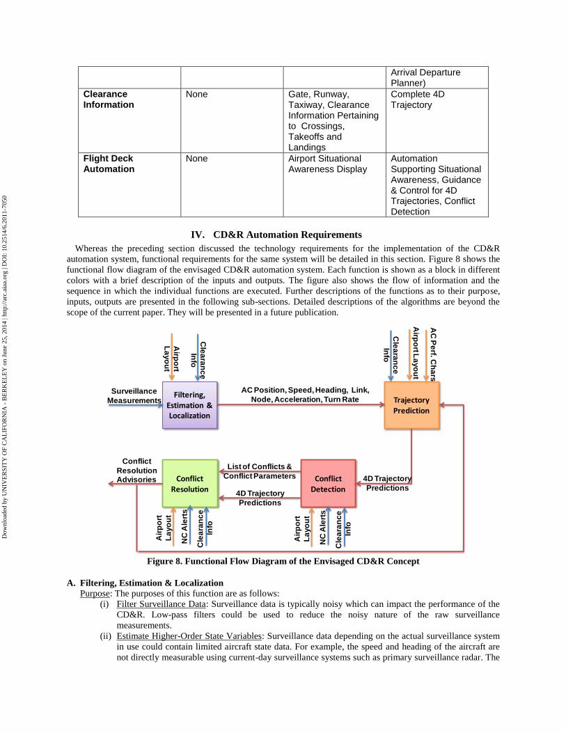
IV. CD&R Automation Requirements

Whereas the preceding section discussed the technology requirements for the implementation of the CD&R

automation system, functional requirements for the same system will be detailed in this section. Figure 8 shows the

functional flow diagram of the envisaged CD&R automation system. Each function is shown as a block in different

colors with a brief description of the inputs and outputs. The figure also shows the flow of information and the

sequence in which the individual functions are executed. Further descriptions of the functions as to their purpose,

inputs, outputs are presented in the following sub-sections. Detailed descriptions of the algorithms are beyond the

scope of the current paper. They will be presented in a future publication.

Filtering, Estimation & Localization

Surveillance

Measurements

Conflict Detection

Conflict Resolution

Trajectory Prediction

Airp

ort

La

yo

ut

Cle

ara

nc

e

Info

AC Position, Speed, Heading, Link,

Node, Acceleration, Turn Rate

Airp

ort L

ayo

ut

Cle

ara

nc

e

Info

List of Conflicts &

Conflict Parameters

Conflict

Resolution Advisories

AC

Pe

rf. Ch

ars

4D Trajectory

Predictions

4D Trajectory

Predictions

Air

po

rt

La

yo

ut

Cle

ara

nc

e

Info

NC

Ale

rts

Air

po

rt

La

yo

ut

Cle

ara

nc

e

Info

NC

Ale

rts

Figure 8. Functional Flow Diagram of the Envisaged CD&R Concept

A. Filtering, Estimation & Localization

Purpose: The purposes of this function are as follows:

(i) Filter Surveillance Data: Surveillance data is typically noisy which can impact the performance of the

CD&R. Low-pass filters could be used to reduce the noisy nature of the raw surveillance

measurements.

(ii) Estimate Higher-Order State Variables: Surveillance data depending on the actual surveillance system

in use could contain limited aircraft state data. For example, the speed and heading of the aircraft are

not directly measurable using current-day surveillance systems such as primary surveillance radar. The

Dow

nloa

ded

by U

NIV

ER

SIT

Y O

F C

AL

IFO

RN

IA -

BE

RK

EL

EY

on

June

25,

201

4 | h

ttp://

arc.

aiaa

.org

| D

OI:

10.

2514

/6.2

011-

7050

estimation function in this case would estimate the speed and heading angle of the aircraft. The

estimation function can also be used to estimate acceleration level states which can be used to better

predict the aircraft’s future motion, in turn leading to more accurate conflict detection.

(iii) Localize the Aircraft: Whereas the surveillance data generates position coordinates of the aircraft with

respect to some reference frame, it is of interest to map these coordinates on to the geometric layout of

the airport and associate a link and node to each aircraft.

Inputs: Surveillance measurements. The nature of these measurements is dependent upon the type of surveillance

system (e.g., PSR, ADS-B). The number of aircraft states available for measurement, their accuracy and update rate

can be different for individual surveillance systems.

Outputs: Aircraft state vector. The aircraft state vector can consist of multiple pieces of aircraft information such

as position (x, y) coordinates, link, node, speed, heading, and possibly acceleration and turn-rate also. The number of

components of the state vector depends on their observability with respect to the available surveillance

measurements.

B. Trajectory Prediction

Purpose: A rigorous approach to predicting conflicts requires accurate prediction of aircraft trajectories. An

essential precursor to the prediction of trajectories is the inference trajectory parameters such as the route, speed, and

turn rates. The parameters are then used to synthesize 4D trajectories suitable for conflict detection. Trajectory

prediction can be done from a strategic perspective using intent information and also from a tactical perspective

using only the current aircraft state information. Tactical trajectory prediction will also be useful for ground vehicles

of which the intent is not necessarily known to the automation system. Another level of sophistication in trajectory

prediction involves the usage of stochastic trajectory models to represent the uncertainty associated with the

trajectory predictions.

Inputs: AC state estimates from the filtering, estimation, and localization module, layout of the airport,

configuration of the airport, aircraft performance characterstics, and most importantly clearance information (if

available, including conflict resolutions).

Outputs: Time history of the aircraft position variables (t, x, y, z) starting from the current time and ending at

some selected time instant in the future. Stochastic trajectory predictions are also expected to output the uncertainty

associated with the predictions using a probability distribution.

C. Conflict Detection

Purpose: The purpose of conflict detection function is to parse the 4D-trajectory predictions and determine if any

pair of aircraft is expected to violate required safety criteria. The predicted states of every pair of aircraft are

evaluated using a conflict definition. Conflict definition involves defining the conflicts in terms of a pair of aircraft

states using mathematical and logical operators. The definition of conflict could simply be that two aircraft be

separated by a certain pre-chosen distance or it could be more complex as is the case with runway incursions.

Inputs: Inputs for this function are the predicted 4D trajectories and non-conformance alerts.

Outputs: Conflicting aircraft IDs, time to conflict, location of the conflict, predicted minimum separation.

D. Conflict Resolution

Purpose: The purpose of the conflict resolution function is to stop or slow aircraft or cancel clearances as needed

to avoid a collision or violation, re-plan aircraft movements to recover from the conflict situation, and issue

advisories.

Inputs: List of conflicts and conflict parameters from the Conflict Detection module and non-conformance alerts

from conformance monitoring function.

Outputs: In the near-term and mid-term NextGen timeframe, clearance advisories will take the form of the current

voice communications that tell the flights to stop, go behind another aircraft, depart, cross, go around, and change

taxi route. In the far term it is anticipated that advisories can be in the form of 4D trajectories.

Dow

nloa

ded

by U

NIV

ER

SIT

Y O

F C

AL

IFO

RN

IA -

BE

RK

EL

EY

on

June

25,

201

4 | h

ttp://

arc.

aiaa

.org

| D

OI:

10.

2514

/6.2

011-

7050

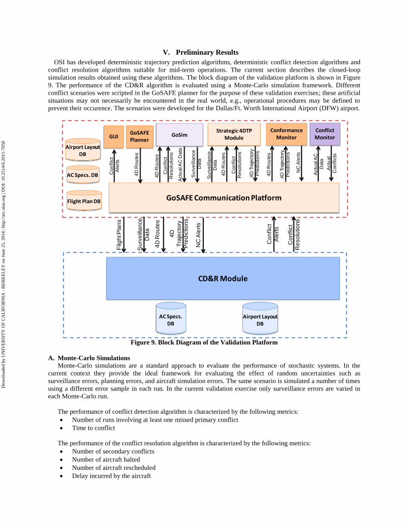
V. Preliminary Results

OSI has developed deterministic trajectory prediction algorithms, deterministic conflict detection algorithms and

conflict resolution algorithms suitable for mid-term operations. The current section describes the closed-loop

simulation results obtained using these algorithms. The block diagram of the validation platform is shown in Figure

9. The performance of the CD&R algorithm is evaluated using a Monte-Carlo simulation framework. Different

conflict scenarios were scripted in the GoSAFE planner for the purpose of these validation exercises; these artificial

situations may not necessarily be encountered in the real world, e.g., operational procedures may be defined to

prevent their occurence. The scenarios were developed for the Dallas/Ft. Worth International Airport (DFW) airport.

AC Specs. DB

Airport Layout DB

CD&R Module

Flig

ht P

lan

s

4D

Tra

jecto

ry

Pre

dic

tio

ns

GoSAFE Communication Platform

GoSAFEPlanner

GoSimGUI

Co

nflic

t

Ale

rts

Co

nflic

t

Re

so

lutio

ns

Co

nfl

ict

Ale

rts

4D

Ro

ute

s

4D

Ro

ute

sS

urv

eill

an

ce

Da

ta

4D

Ro

ute

s

Flight Plan DB

Airport Layout DB

AC Specs. DB

Strategic 4DTP Module

Su

rve

illa

nce

Da

ta

Su

rve

illa

nce

Da

ta

4D

Tra

jecto

ry

Pre

dic

tio

ns

4D

Ro

ute

s

Conformance Monitor

4D

Tra

jecto

ry

Pre

dic

tio

ns

4D

Ro

ute

s

NC

Ale

rts

NC

Ale

rts

Conflict Monitor

Actu

al A

C D

ata

Actu

al A

C

Da

ta

Actu

al

Co

nfl

icts

Co

nfl

ict

Re

so

lutio

ns

Co

nfl

ict

Re

so

lutio

ns

Figure 9. Block Diagram of the Validation Platform

A. Monte-Carlo Simulations

Monte-Carlo simulations are a standard approach to evaluate the performance of stochastic systems. In the

current context they provide the ideal framework for evaluating the effect of random uncertainties such as

surveillance errors, planning errors, and aircraft simulation errors. The same scenario is simulated a number of times

using a different error sample in each run. In the current validation exercise only surveillance errors are varied in

each Monte-Carlo run.

The performance of conflict detection algorithm is characterized by the following metrics:

Number of runs involving at least one missed primary conflict

Time to conflict

The performance of the conflict resolution algorithm is characterized by the following metrics:

Number of secondary conflicts

Number of aircraft halted

Number of aircraft rescheduled

Delay incurred by the aircraft

Dow

nloa

ded

by U

NIV

ER

SIT

Y O

F C

AL

IFO

RN

IA -

BE

RK

EL

EY

on

June

25,

201

4 | h

ttp://

arc.

aiaa

.org

| D

OI:

10.

2514

/6.2

011-

7050

B. Taxiway Head-On Collision

Figure 10 shows a snapshot of a taxiway head-on collision between flight AAL1117 and flight AAL1116

detected 170 seconds before the occurrence of the conflict. The conflicting aircraft are indicated by yellow circles

and the locations of the aircraft at the time of the conflict are indicated in yellow squares. AAL1117 would make a

right turn on to the link occupied by AAL1116 and AAL1448 at the time of conflict.

AAL1117

AAL1544

AAL1116

AAL1448

Figure 10. Snapshot of the CD&R GUI Capturing the Head-On Collision

The conflict resolution algorithm in this case first issues a halt advisory to AAL1117. However, this leads to a

secondary conflict with AAL1544 which results in a halt advisory for AAL1544 as shown in Figure 11. The

conflict resolution algorithm then computes new schedules for the two aircraft along the same taxiway routes that

were assigned to them before the conflict.

Dow

nloa

ded

by U

NIV

ER

SIT

Y O

F C

AL

IFO

RN

IA -

BE

RK

EL

EY

on

June

25,

201

4 | h

ttp://

arc.

aiaa

.org

| D

OI:

10.

2514

/6.2

011-

7050

AAL1117

AAL1544

AAL1116 AAL1448

Figure 11. Snapshot of the CD&R GUI with the Halt Advisories Issued

The performance of the CD&R algorithm has been evaluated in 199 Monte-Carlo simulations runs, each run

resulting in a different surveillance time history. The Monte-Carlo simulation settings for this scenario are shown in

Table 8. The CD trajectory time step refers to the time discretization used by the conflict detection algorithm. TP

refers to trajectory prediction. The performance of the conflict detection and conflict resolution algorithms are

shown in Table 9 and Table 10, respectively. The primary conflict is identified in all Monte-Carlo runs at least 168

seconds before the occurrence of the conflict. It should be noted that the time horizon for trajectory prediction is 180

seconds which also would be the upper limit on the ―Time to Conflict.‖

Table 8. Monte-Carlo Simulation Settings

Dow

nloa

ded

by U

NIV

ER

SIT

Y O

F C

AL

IFO

RN

IA -

BE

RK

EL

EY

on

June

25,

201

4 | h

ttp://

arc.

aiaa

.org

| D

OI:

10.

2514

/6.2

011-

7050

Table 9. Conflict Detection Performance

The performance of the conflict resolution is consistent in all but one Monte-Carlo run that resulted in a delay of

316 seconds for AAL1117.

Table 10. Conflict Resolution Performance

C. Runway Incursion Scenario 1

The runway incursion scenario shown in Figure 12 involves a departure aircraft, EFG643, and an arrival aircraft,

EFG642, which has just landed and is attempting to cross the same runway. In the current implementation of the

conflict resolution algorithm for runway incursions, all the crossing aircraft are stopped and the departure aircraft are

given precedence in using the runway. Figure 13 shows the halt advisories issued to EFG642 (in the upper right

table of the display) as well as another crossing aircraft, AAL1118, which was supposed to cross the runway after

EFG643 and before AAL730. The conflict resolution algorithm instead allows the two departure flights EFG643 and

AAL730 to take off first and then issues the clearance for the crossing flights EFG642 and AAL1118. The second

departure flight AAL730 benefits from this resolution and departs 23 seconds earlier. Detailed descriptions of the

performance metrics is given in Table 11–Table 13.

Dow

nloa

ded

by U

NIV

ER

SIT

Y O

F C

AL

IFO

RN

IA -

BE

RK

EL

EY

on

June

25,

201

4 | h

ttp://

arc.

aiaa

.org

| D

OI:

10.

2514

/6.2

011-

7050

EGF643

EGF642

Figure 12. Snapshot of the CD&R GUI after the Runway Incursion Is Detected

EGF642

AAL1118

AAL730

Figure 13. Snapshot of the CD&R GUI after the Halt Advisories Are Issued

Dow

nloa

ded

by U

NIV

ER

SIT

Y O

F C

AL

IFO

RN

IA -

BE

RK

EL

EY

on

June

25,

201

4 | h

ttp://

arc.

aiaa

.org

| D

OI:

10.

2514

/6.2

011-

7050

Table 11. Monte-Carlo Simulation Settings

Table 12. Conflict Detection Performance

Table 13. Conflict Resolution Performance

Dow

nloa

ded

by U

NIV

ER

SIT

Y O

F C

AL

IFO

RN

IA -

BE

RK

EL

EY

on

June

25,

201

4 | h

ttp://

arc.

aiaa

.org

| D

OI:

10.

2514

/6.2

011-

7050

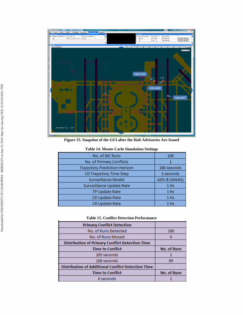
D. Runway Incursion Scenario 2

The previous runway incursion scenario involved a conflict between departing aircraft and crossing aircraft. The

current scenario involves a crossing aircraft, AAL1446, and an arrival aircraft, AAL1447, which is about to land.

The locations of the conflicting aircraft at the time of the conflict are shown with yellow squares in Figure 14.

Conflict resolution issues a halt advisory to AAL1446 which results in a secondary conflict with AAL1118 that is

also halted as shown in Figure 15. Both flights AAL1446 and AAL1118 are issued new schedules. The performance

of the CD&R algorithm evaluated using Monte-Carlo simulations is given in Table 14–

Table 16.

AAL1446

Figure 14. Snapshot of the GUI after the Runway Incursion Is Detected

Dow

nloa

ded

by U

NIV

ER

SIT

Y O

F C

AL

IFO

RN

IA -

BE

RK

EL

EY

on

June

25,

201

4 | h

ttp://

arc.

aiaa

.org

| D

OI:

10.

2514

/6.2

011-

7050

AAL1446

AAL1118

AAL1447

Figure 15. Snapshot of the GUI after the Halt Advisories Are Issued

Table 14. Monte-Carlo Simulation Settings

Table 15. Conflict Detection Performance

Dow

nloa

ded

by U

NIV

ER

SIT

Y O

F C

AL

IFO

RN

IA -

BE

RK

EL

EY

on

June

25,

201

4 | h

ttp://

arc.

aiaa

.org

| D

OI:

10.

2514

/6.2

011-

7050

Table 16. Conflict Resolution Performance

VI. Conclusion

The paper discusses the role of a surface conflict detection and resolution automation system in the context of

near-term, mid-term, and far-term operations. It draws out the differences in the enabling technologies that are

expected to be available to the conflict detection and resolution system in the three different timeframes. Functional

requirements generated as part of this paper are expected to form the basis for the design of conflict detection and

resolution algorithms. Preliminary closed-loop simulation results indicate the importance of intent-based trajectory

prediction algorithms for effective conflict detection as well as resolution. Work related to development as well

improvement of the algorithms for estimation, localization, trajectory prediction, conflict detection, and conflict

resolution is currently in progress.

Acknowledgments

This research has been performed under NASA support through an NRA contract from Ames Research Center.

The authors thank Ms. Sandy Lozito, Dr. Yoon-Jung, and other researchers from the Safe and Efficient Surface

Operations (SESO) group for their inputs, suggestions, and feedback.

Dow

nloa

ded

by U

NIV

ER

SIT

Y O

F C

AL

IFO

RN

IA -

BE

RK

EL

EY

on

June

25,

201

4 | h

ttp://

arc.

aiaa

.org

| D

OI:

10.

2514

/6.2

011-

7050

References 1Airport Surface Detection Equipment—Model X (ASDE-X), NAS Subsystem Level Specification, Version 1.1,

Federal Aviation Administration, Washington DC, May 24, 2001. 2Scardina, J., ―Overview of the FAA ADS-B Link Decision,‖ Office of System Architecture and Investment

Analysis, Federal Aviation Administration, June 7, 2002. 3Capezzutto, V., Olster, D., Curry, M., and Pendergast, S. L., ―Runway Incursion Reduction Program

Surveillance System, NASA/FAA Atlanta Demonstration‖, Proceedings of 17th Digital Avionics Conference, 1998. 4Ianiello, J. W., and Kruczek, R. M., ―Airport Surface Collision Warning System Implementation‖, Proceedings

of the Vehicle Navigation and Information Systems Conference, 1993. 5Eggert, J. R., B. R. Howes, M. Picardi Kuffner, H. Wilhelmsen, and D. J. Bernays, ―Operational Evaluation of

Runway Status Lights,‖ Lincoln Laboratory Journal, Vol. 16, No. 1, 2003 6Foyle, D. C., A. D. Andre, R. S. McCann, E. M. Wenzel, D. R. Begault, and V. Battiste, ―Taxiway Navigation

and Situation Awareness (T-NASA) System: Problem, Design Philosophy, and Description of an Integrated Display

Suite for Low-Visibility Airport Surface Operations,‖ SAE Transactions: Journal of Aerospace, Vol. 105, pp. 1411–

1418, 1996. 7McCann, R. S., D. C. Foyle, B. L. Hooey, A. D. Andre, B. Parke, and B. Kanki, ―An Evaluation of the

Taxiway Navigation and Situation Awareness (T-NASA) System in High-Fidelity Simulation,‖ SAE Transactions:

Journal of Aerospace, Vol. 107 , 1612–1625, 1998. 8Jones, D., ―Runway Incursion Prevention System – Demonstration and Testing at the Dallas/Fort Worth

International Airport,‖ Proceedings of the 20th Digital Avionics Systems Conference, Daytona Beach, FL, 2001. 9Young, S. D., and D. R. Jones, ―Runway Incursion Prevention: A Technology Solution,‖ Proceedings of the

Flight Safety Foundation 54th Annual International Air Safety Seminar, 54, 1–22, Athens, Greece: Flight Safety

Foundation, 2001. 10

Jones, D. R., ―Collision Avoidance for Airport Traffic (CAAT),‖ NASA Airspace Systems Program Technical

Interchange Meeting, Austin, TX, March 18–20, 2008. 11

Anon, ―Runway Incursion Alerting System,‖ Information Brochure by QinetiQ. 12

Atkins, S., and C. Brinton, ―Concept Description and Development Plan for the Surface Management

System,‖ Journal of Air Traffic Control, 2002. 13

Atkins, S., Y. Jung, C. Brinton, S. Stell, and S. Rogowski, ―Surface Management System Field Trial Results,‖

Proceedings of the AIAA 4th Aviation Technology, Integration and Operations (ATIO) Forum, Chicago, IL,

September 20–22, 2004, Paper AIAA 2004-6241. 14

Brinton, C. R., S. C. Atkins, and A. Hall, ―Analysis of Taxi Conformance Monitoring Algorithms and

Performance,‖ 7th Integrated Communications, Navigation, and Surveillance (ICNS) Conference, Herndon, VA,

May 1–3, 2007. 15

Pledgie, S., B. Gallet, Y. Zhao and D. Wu, ―4D Surface Trajectory Synthesis,‖ NASA Airspace Systems

Program Technical Interchange Meeting, San Antonio, TX, October 13–16, 2009. 16

Meier, C., J. Jakobi, P. Adamson, S. Lozito, and L. Martin, ―Benefits of Advanced Surface Movement

Guidance and Control Systems (A-SMGCS),‖ Air Traffic Control Quarterly, Vol. 13, No. 4, pp. 329–356, 2006. 17

Smeltink, J. W., M. J. Soomer, P. R. de Waal, and R. D. van der Mei, ―An Optimisation Model for Airport

Taxi Scheduling,‖ Technical Report, National Aerospace Laboratory NLR, June 11, 2004. 18

―Operational Requirements Document (ORD-Update),‖ Document No. D1.3.5, Version No. 1.0, European

Airport Movement Management by A-SMGCS (EMMA), April 25, 2006. 19

Moller, M., ―EMMA Air-Ground Operational Service and Environmental Description (OSED-update),‖

Document No. D1.3.1.u, Version No. 1.0, European Airport Movement Management by A-SMGCS (EMMA), April

25, 2006. 20

Jakobi, J., ―A-SMGCS Services, Procedures, and Operational Requirements (SPOR): A Preliminary Concept

and Framework for Validation Activities in EMMA2,‖ Document No. 2-D1.1.1, Version No. 1.0, European Airport

Movement Management by A-SMGCS (EMMA), December 2, 2008. 21

―Air Transportation System Capacity-Increasing Concepts Research — Surface Operation Automation

Research (SOAR),‖ NASA Contract No. NAS2-02073, funded by NASA Ames Research Center, April 15, 2002,

Optimal Synthesis Inc., Los Altos, CA. 22

Cheng, V. H. L., ―Collaborative Automation Systems for Enhancing Airport Surface Traffic Efficiency and

Safety,‖ Proceedings of the 21st IEEE/AIAA Digital Avionics Systems Conference, Irvine, CA, October 29–31,

2002, Paper 1D4.

Dow

nloa

ded

by U

NIV

ER

SIT

Y O

F C

AL

IFO

RN

IA -

BE

RK

EL

EY

on

June

25,

201

4 | h

ttp://

arc.

aiaa

.org

| D

OI:

10.

2514

/6.2

011-

7050

23Cheng, V. H. L., ―Airport Surface Operation Collaborative Automation Concept,‖ Proc. AIAA Guidance,

Navigation, and Control Conf., Austin, TX, August 11–14, 2003, AIAA Paper 2003-5773. 24

Cheng, V. H. L., ―Surface Operation Automation Research for Airport Tower and Flight Deck Automation,‖

Proceedings of the 2004 IEEE Intelligent Transportation Systems (2004 ITSC), Washington, DC, October 3–5,

2004, Paper TuC2.4. 25

Cheng, V. H. L., ―Research Progress on an Automation Concept for Surface Operation with Time Based

Trajectories,‖ 7th Integrated Communications, Navigation, and Surveillance (ICNS) Conference, Herndon, VA,

May 1–3, 2007. 26

Cheng, V. H. L., V. Sharma, and D. C. Foyle, ―Study of Aircraft Taxi Performance for Enhancing Airport

Surface Traffic Control,‖ IEEE Trans. Intelligent Transportation Systems, Vol. 2, No. 2, pp. 39–54, June 2001. 27

Sweriduk, G. D., V. H. L. Cheng, A. D. Andre, and D. C. Foyle, ―Automation Tools for High-Precision

Taxiing,‖ submitted for presentation at the 26th

Digital Avionics Systems Conference, Dallas, TX, October 21–25,

2007. 28

Cheng, V. H. L., G. D. Sweriduk, C. H. Yeh, A. D. Andre, and D. C. Foyle, ―Flight-Deck Automation for

Collaborative Surface Operation Concept,‖ accepted for presentation at the AIAA Guidance, Navigation, and

Control Conf., Honolulu, HI, August 18–21, 2008. 29

FAA Advisory Circular AC-150-5340-1, U. S. Dept. of Transportation, Federal Aviation Administration,

Washington, DC, 200X. 30

FAA Advisory Circular AC-150-5340-18, U. S. Dept. of Transportation, Federal Aviation Administration,

Washington, DC, 200X. 31

FAA Aeronautical Information Manual: Official Guide to Basic Flight Information and ATC Procedures, U.

S. Dept. of Transportation, Federal Aviation Administration, Washington, DC, 2004. 32

http://www.flightglobal.com/articles/2007/04/10/213116/faa-sets-2017-atc-datalink-deadline.html 33

Cheng, V. H. L., Crawford, L. S., Lam, T., and Sweriduk, G. D, ―Navigation and Situational Awareness for

Landing and Runway Crossing, Ground-Operation Situational Awareness and Flow Efficiency (GO-SAFE),‖ Final

Report Prepared Under NASA SBIR Contract No. NAS2-9905, June, 2001. 34

Wei, W., J. Tsao, L. Martin, J. Poage, V. Cheng, A. Seo, and D. David, ―Integrated Approaches for Surface

Traffic Optimization in the Presence of Uncertainties,‖ NASA Airspace Systems Program Technical Interchange

Meeting, Austin, TX, March 18–20, 2008. 35

Jung, Y. C., Hoang, T., Montoya, J., Gupta, G., Malik, W., and Toibas, L., ―A Concept and Implementation of

Optimized Operations of Airport Surface Traffic,‖ Proceedings of the 2010 AIAA Aviation, Technology, Integration

and Operations Conference, September, 2010. 36

Malik, W., Gupta, G., and Jung, Y. C., ―Managing Departure Airport Release for Efficient Airport Surface

Operations,‖ Proceedings of the 2010 AIAA Guidance, Navigation, Control Conference and Exhibit, August, 2010. 37

Gupta, G., Malik, W., and Jung, Y. C., ―A Mixed Integer Linear Program for Airport Departure Scheduling,‖

Proceedings of the 2009 AIAA Aviation, Technology, Integration and Operations Conference, September, 2009. 38

Gupta, G., Malik, W., and Jung, Y. C., ―Incorporating Active Runway Crossings in Airport Departure

Scheduling,‖ Proceedings of the 2010 AIAA Guidance, Navigation, Control Conference and Exhibit, August, 2010. 39

Rathinam, S., Montoya, J., and Jung, Y. C., ―An Optimization Model for Reducing Aircraft Taxi Times at the

Dallas Fort Worth International Airport,‖ Proceedings of the 2008 AIAA Aviation, Technology, Integration and

Operations Conference, September, 2008. 40

Rathinam, S., J. Montoya, and Y. Jung, ―Algorithms for Scheduling and Routing of Aircraft at Airports,‖

NASA Airspace Systems Program Technical Interchange Meeting, Austin, TX, March 18–20, 2008.

Dow

nloa

ded

by U

NIV

ER

SIT

Y O

F C

AL

IFO

RN

IA -

BE

RK

EL

EY

on

June

25,

201

4 | h

ttp://

arc.

aiaa

.org

| D

OI:

10.

2514

/6.2

011-

7050


Recommended