-1- AECL - OFFICIAL USE ONLY / À USAGE EXCLUSIF - EACL Concept Review of Canadian Supercritical Water Reactor and Probabilistic Safety Assessment Thambiayah (Nithy) Nitheanandan 2015 March 24
Transcript
-1- AECL - OFFICIAL USE ONLY / À USAGE EXCLUSIF - EACL
Concept Review of Canadian Supercritical Water
Reactor and Probabilistic Safety Assessment
Thambiayah (Nithy) Nitheanandan
2015 March 24
-2- AECL - OFFICIAL USE ONLY / À USAGE EXCLUSIF - EACL
Outline
Introduction
Canadian Supercritical Water Reactor Design
Features
Physics Design and Analysis
Fuel Channel and Material Selection
Thermalhydraulics Analysis
Safety Philosophy for Canadian SCWR
Summary
-3- AECL - OFFICIAL USE ONLY / À USAGE EXCLUSIF - EACL
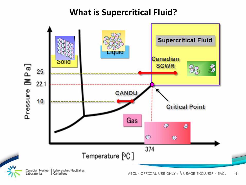
What is Supercritical Fluid?
-4- AECL - OFFICIAL USE ONLY / À USAGE EXCLUSIF - EACL
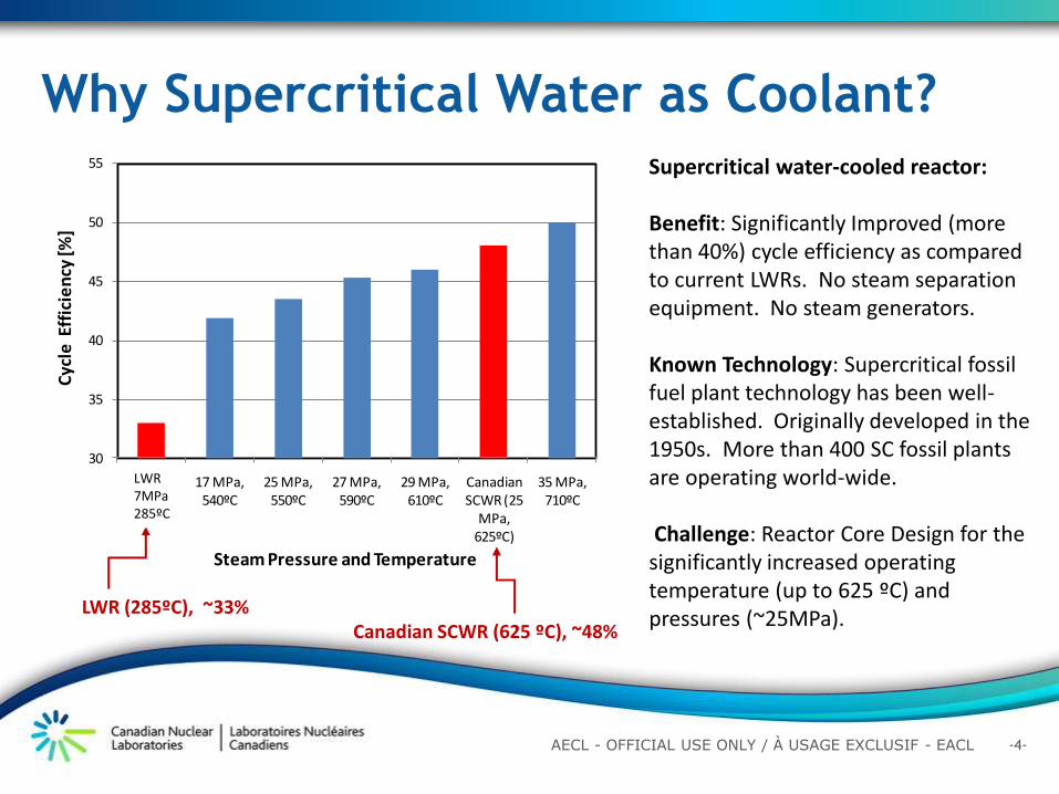
Why Supercritical Water as Coolant? Supercritical water-cooled reactor: Benefit: Significantly Improved (more than 40%) cycle efficiency as compared to current LWRs. No steam separation equipment. No steam generators. Known Technology: Supercritical fossil fuel plant technology has been well-established. Originally developed in the 1950s. More than 400 SC fossil plants are operating world-wide. Challenge: Reactor Core Design for the significantly increased operating temperature (up to 625 ºC) and pressures (~25MPa).
LWR (285ºC), ~33% Canadian SCWR (625 ºC), ~48%
30
35
40
45
50
55
CANDU 6 (5 MPa, 265ºC)
17 MPa, 540ºC
25 MPa, 550ºC
27 MPa, 590ºC
29 MPa, 610ºC
Canadian SCWR (25
MPa, 625ºC)
35 MPa, 710ºC
Cyc
le E
ffic
ien
cy [%
]
Steam Pressure and Temperature
LWR 7MPa 285ºC
-5- AECL - OFFICIAL USE ONLY / À USAGE EXCLUSIF - EACL
Outline
Introduction
Canadian Supercritical Water Reactor Design
Features
Physics Design and Analysis
Fuel Channel and Material Selection
Thermalhydraulics Analysis
Safety Philosophy for Canadian SCWR
Summary
-6- AECL - OFFICIAL USE ONLY / À USAGE EXCLUSIF - EACL
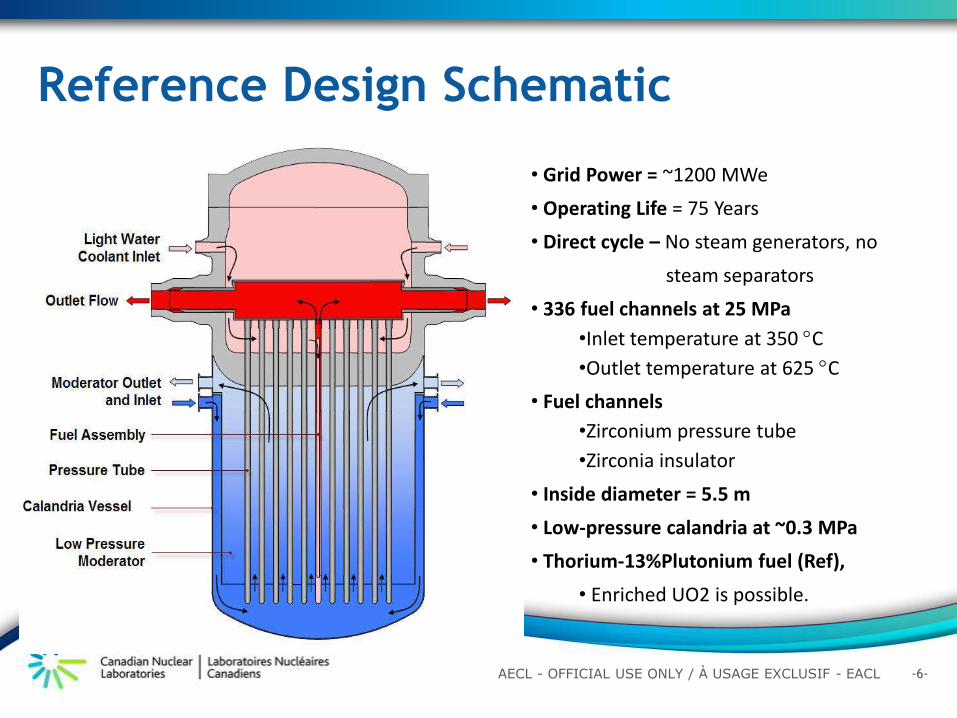
Reference Design Schematic
• Grid Power = ~1200 MWe
• Operating Life = 75 Years
• Direct cycle – No steam generators, no
steam separators
• 336 fuel channels at 25 MPa
•Inlet temperature at 350 C
•Outlet temperature at 625 C
• Fuel channels
•Zirconium pressure tube
•Zirconia insulator
• Inside diameter = 5.5 m
• Low-pressure calandria at ~0.3 MPa
• Thorium-13%Plutonium fuel (Ref),
• Enriched UO2 is possible.
-7- AECL - OFFICIAL USE ONLY / À USAGE EXCLUSIF - EACL
• SCW is single-phase fluid. Hence, no steam separators (as in BWRs) or steam generators (as in PWRs and CANDUs) are needed. As a result, a direct steam cycle is adopted.
• SCW turbine technology is mature. SCW turbines exist that operate at 600ºC.
• Batch fuelling and vertical orientation are adopted. This allows the use of a simpler gantry crane fuelling machine instead of a high-pressure robotic on-line fuelling machine typical in CANDUs,
• Passive safety systems are adopted for all safety cases. These systems have very few or no moving components, and hence are more reliable and simpler to maintain.
Main design features and simplifications
-8- AECL - OFFICIAL USE ONLY / À USAGE EXCLUSIF - EACL
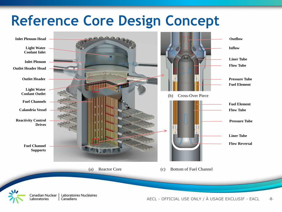
Reference Core Design Concept
Light Water
Coolant Inlet
Inlet Plenum
Outlet Header Head
Outlet Header
Fuel Channels
Calandria Vessel
Fuel Channel
Supports
Light Water
Coolant Outlet
Outflow
Inflow
Liner Tube
Flow Tube
Pressure Tube
Fuel Element
Fuel Element
Flow Tube
Liner Tube
Pressure Tube
Flow Reversal
Inlet Plenum Head
(a) Reactor Core
(b) Cross-Over Piece
(c) Bottom of Fuel Channel
Reactivity Control
Drives
-9- AECL - OFFICIAL USE ONLY / À USAGE EXCLUSIF - EACL
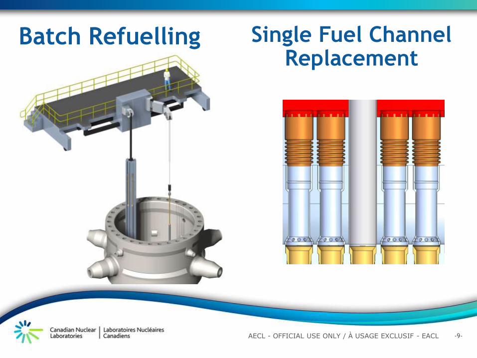
Batch Refuelling Single Fuel Channel Replacement
-10- AECL - OFFICIAL USE ONLY / À USAGE EXCLUSIF - EACL
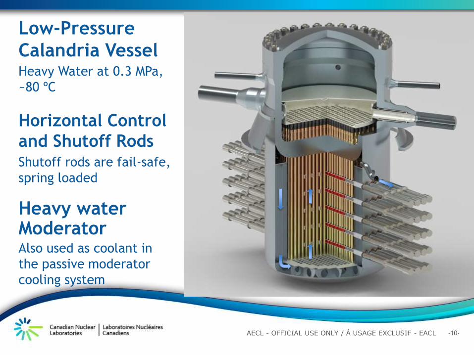
Low-Pressure
Calandria Vessel Heavy Water at 0.3 MPa,
~80 ºC
Horizontal Control
and Shutoff Rods Shutoff rods are fail-safe,
spring loaded
Heavy water Moderator Also used as coolant in
the passive moderator
cooling system
-11- AECL - OFFICIAL USE ONLY / À USAGE EXCLUSIF - EACL
Inlet plenum and outlet header connections
Inlet Plenum Head
Inlet Plenum
Coolant Inlet Nozzle
Coolant Outlet Nozzle
Tubesheet
Outlet Header Head
Outlet Header
Pressure Tube Extension
Outlet Header Supports
-12- AECL - OFFICIAL USE ONLY / À USAGE EXCLUSIF - EACL
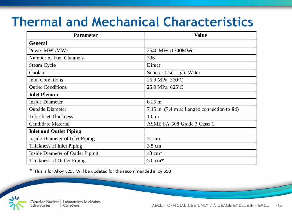
Thermal and Mechanical Characteristics Parameter Value
General
Power MWt/MWe 2540 MWt/1200MWe
Number of Fuel Channels 336
Steam Cycle Direct
Coolant Supercritical Light Water
Inlet Conditions 25.3 MPa, 350ºC
Outlet Conditions 25.0 MPa, 625ºC
Inlet Plenum
Inside Diameter 6.25 m
Outside Diameter 7.15 m (7.4 m at flanged connection to lid)
Tubesheet Thickness 1.0 m
Candidate Material ASME SA-508 Grade 3 Class 1
Inlet and Outlet Piping
Inside Diameter of Inlet Piping 31 cm
Thickness of Inlet Piping 3.5 cm
Inside Diameter of Outlet Piping 43 cm*
Thickness of Outlet Piping 5.0 cm*
* This is for Alloy 625. Will be updated for the recommended alloy 690
-13- AECL - OFFICIAL USE ONLY / À USAGE EXCLUSIF - EACL
Fuel Channel Extensions
(a) Fuel Assembly Support
and Locking Mechanism
(b) Locked
(c) Unlocked
Fuel Assembly
Outlet
Locking Mechanism
Spring
Locking Balls
Metallic ‘E’ Seal
Fuel Channel
Extension
Inner Sleeve
Equipped with
ramp
Locking Balls
(Retracted Position)
Outlet
Header
Locking
Mechanism
Fuel Assembly
Support and
Seal
Inlet Plenum
Tubesheet
Fuel Assembly
-14- AECL - OFFICIAL USE ONLY / À USAGE EXCLUSIF - EACL
Outlet Header Thermal Sleeve
Outlet Header
Thermal Isolation Sleeve
Liner Sleeve
Outlet Piping
Expansion Bellows
Guide Bushing
-15- AECL - OFFICIAL USE ONLY / À USAGE EXCLUSIF - EACL
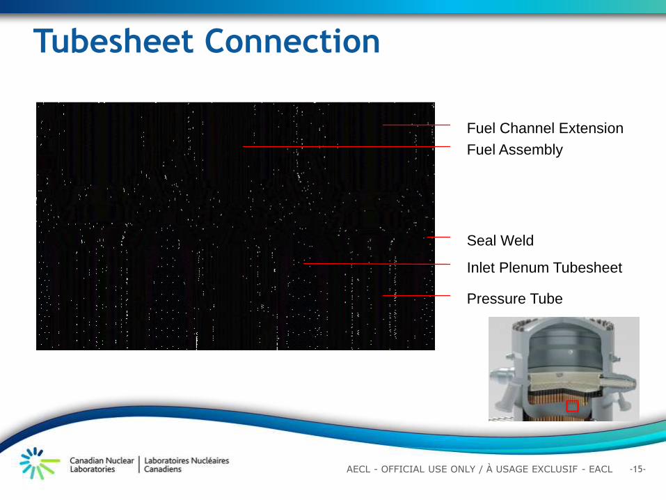
Tubesheet Connection
Fuel Channel Extension
Fuel Assembly
Pressure Tube
Inlet Plenum Tubesheet
Seal Weld
-16- AECL - OFFICIAL USE ONLY / À USAGE EXCLUSIF - EACL
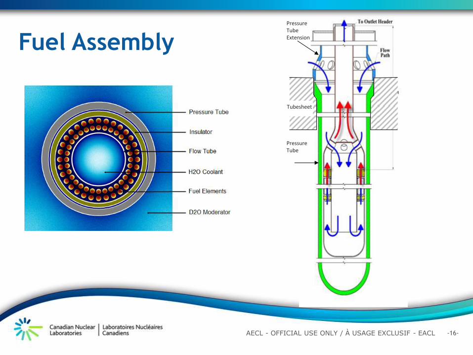
Fuel Assembly
Pressure Tube
Pressure Tube Extension
Tubesheet
-17- AECL - OFFICIAL USE ONLY / À USAGE EXCLUSIF - EACL
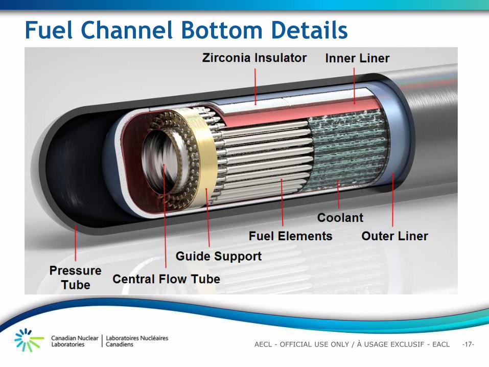
Fuel Channel Bottom Details
-18- AECL - OFFICIAL USE ONLY / À USAGE EXCLUSIF - EACL
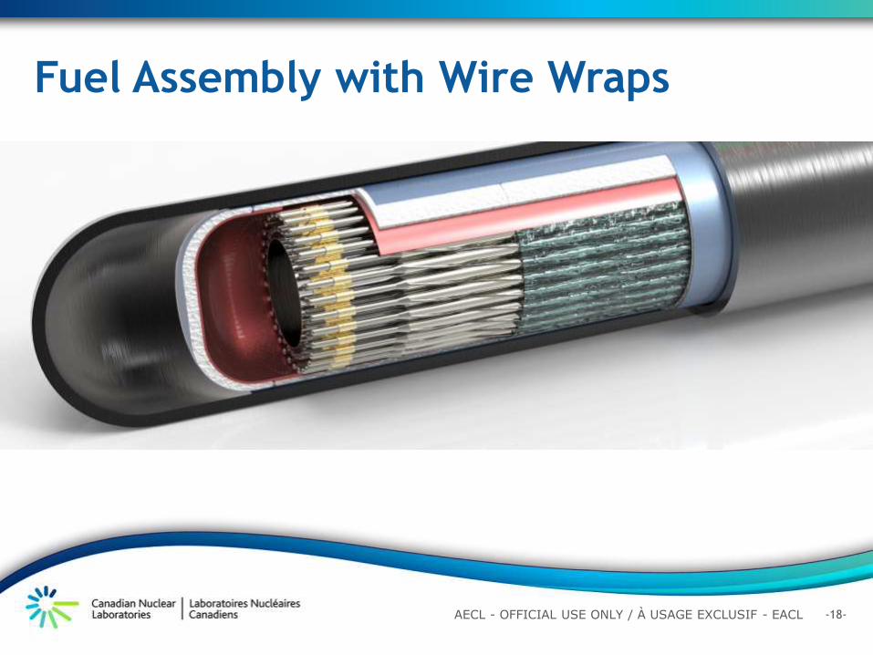
Fuel Assembly with Wire Wraps
-19- AECL - OFFICIAL USE ONLY / À USAGE EXCLUSIF - EACL
Computational Fluid Dynamics (CFD)
Analysis of the Inlet Plenum
7 m/s
30 m/s
-20- AECL - OFFICIAL USE ONLY / À USAGE EXCLUSIF - EACL
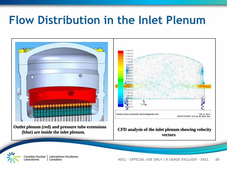
Flow Distribution in the Inlet Plenum
Outlet plenum (red) and pressure tube extensions
(blue) are inside the inlet plenum.
CFD analysis of the inlet plenum showing velocity
vectors
Outlet plenum (red) and pressure tube extensions
(blue) are inside the inlet plenum.
CFD analysis of the inlet plenum showing velocity
vectors
-21- AECL - OFFICIAL USE ONLY / À USAGE EXCLUSIF - EACL
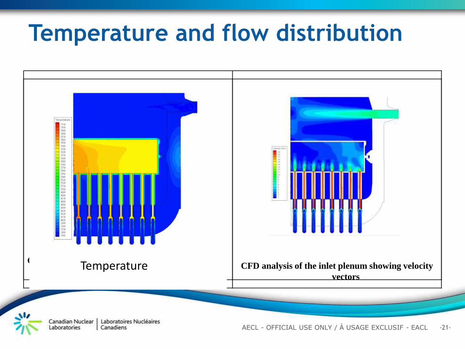
Temperature and flow distribution
Outlet plenum (red) and pressure tube extensions
(blue) are inside the inlet plenum.
CFD analysis of the inlet plenum showing velocity
vectors
Temperature
-22- AECL - OFFICIAL USE ONLY / À USAGE EXCLUSIF - EACL
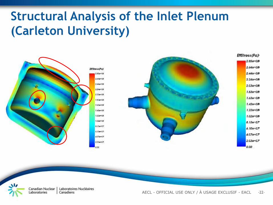
Structural Analysis of the Inlet Plenum
(Carleton University)
-23- AECL - OFFICIAL USE ONLY / À USAGE EXCLUSIF - EACL
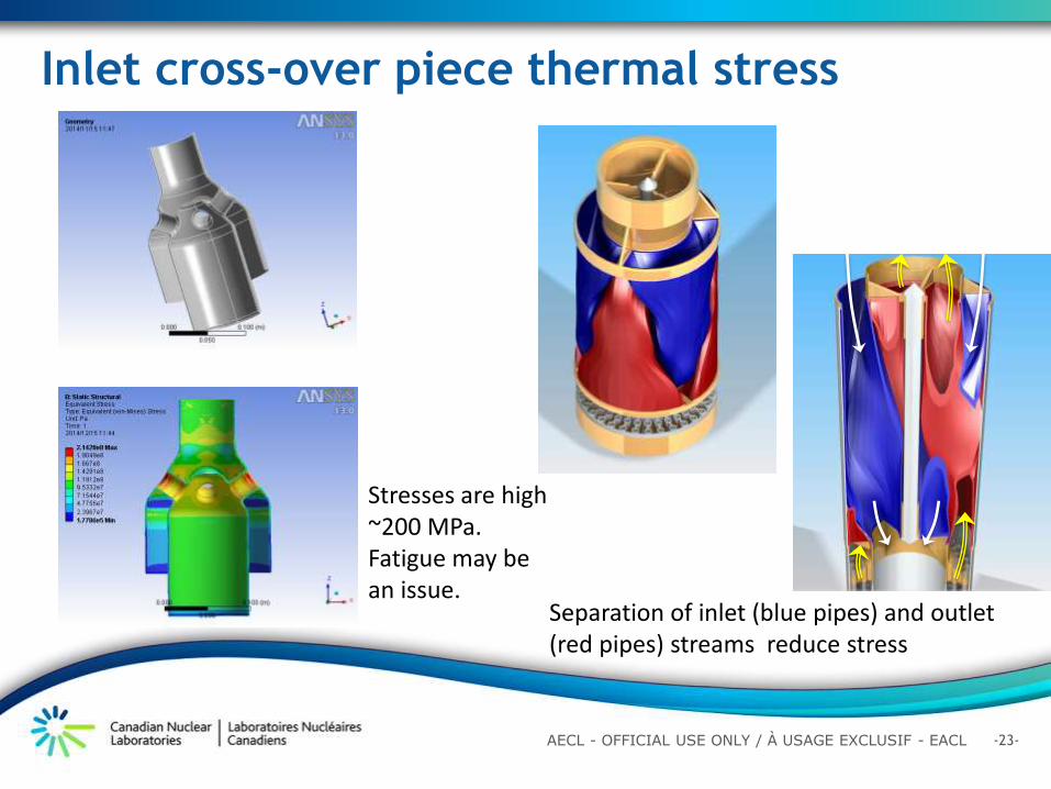
Inlet cross-over piece thermal stress
Stresses are high ~200 MPa. Fatigue may be an issue.
Separation of inlet (blue pipes) and outlet (red pipes) streams reduce stress
-24- AECL - OFFICIAL USE ONLY / À USAGE EXCLUSIF - EACL
Outline
Introduction
Canadian Supercritical Water Reactor Design
Features
Physics Design and Analysis
Fuel Channel and Material Selection
Thermalhydraulics Analysis
Safety Philosophy for Canadian SCWR
Summary
-25- AECL - OFFICIAL USE ONLY / À USAGE EXCLUSIF - EACL
Analytical Tools
•Toolset for conventional HWR modeling:
• Nuclear data libraries: “in-house” ENDF/B-VII.0-based libraries
• Lattice physics: WIMS-AECL
• Post processing: WIMS-UTILITIES
• Core physics: RFSP
-26- AECL - OFFICIAL USE ONLY / À USAGE EXCLUSIF - EACL
WIMS-AECL Lattice Level Modeling
• 2D deterministic code, 89-group cross sections
• Representation of cross section of fuel bundle, channel and surrounding moderator
• Calculates energy and space dependent neutron flux distribution
• Calculates fuel depletion versus time based on flux or power history
-27- AECL - OFFICIAL USE ONLY / À USAGE EXCLUSIF - EACL
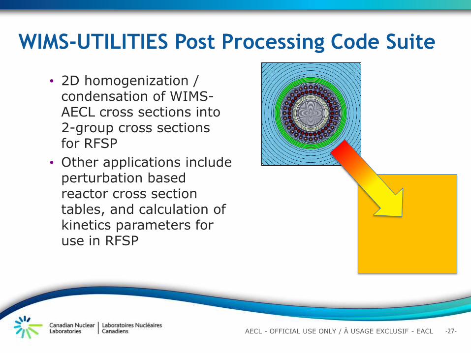
WIMS-UTILITIES Post Processing Code Suite
• 2D homogenization / condensation of WIMS-AECL cross sections into 2-group cross sections for RFSP
• Other applications include perturbation based reactor cross section tables, and calculation of kinetics parameters for use in RFSP
-28- AECL - OFFICIAL USE ONLY / À USAGE EXCLUSIF - EACL
RFSP Core Level Modeling • 3D 2-group neutron
diffusion code
• Solves for k-eff and 3d flux / power distribution
• Core follow mode
• Interpolation of reactor tables gives burnup dependent cross sections
• Transient analysis capable when coupled with T/H code, e.g. CATHENA
-29- AECL - OFFICIAL USE ONLY / À USAGE EXCLUSIF - EACL
Lattice Physics – Generic Behaviour
• Balance between maximizing exit burnup and minimizing CVR
• Similar challenge with power shaping / reactivity suppression and exit burnup
-30- AECL - OFFICIAL USE ONLY / À USAGE EXCLUSIF - EACL
-31- AECL - OFFICIAL USE ONLY / À USAGE EXCLUSIF - EACL
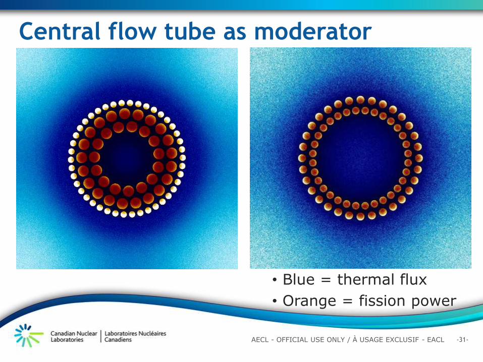
Central flow tube as moderator
• Blue = thermal flux
• Orange = fission power
-32- AECL - OFFICIAL USE ONLY / À USAGE EXCLUSIF - EACL
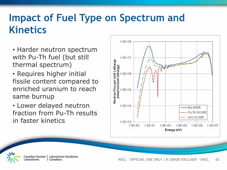
Impact of Fuel Type on Spectrum and
Kinetics
• Harder neutron spectrum with Pu-Th fuel (but still thermal spectrum)
• Requires higher initial fissile content compared to enriched uranium to reach same burnup
• Lower delayed neutron fraction from Pu-Th results in faster kinetics
-33- AECL - OFFICIAL USE ONLY / À USAGE EXCLUSIF - EACL
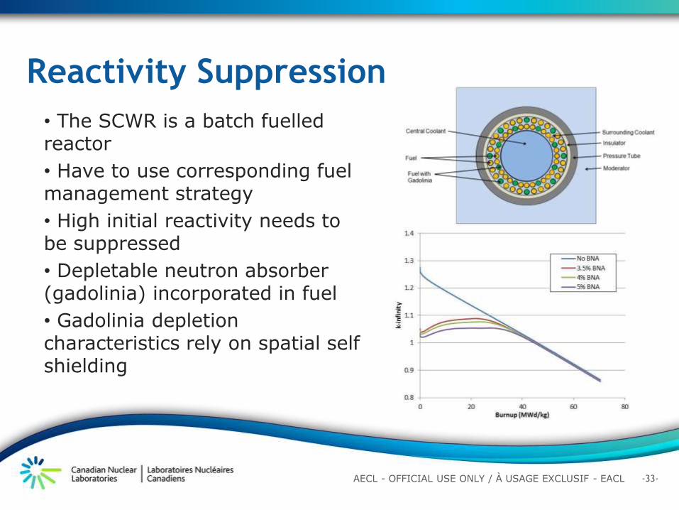
Reactivity Suppression
• The SCWR is a batch fuelled reactor
• Have to use corresponding fuel management strategy
• High initial reactivity needs to be suppressed
• Depletable neutron absorber (gadolinia) incorporated in fuel
• Gadolinia depletion characteristics rely on spatial self shielding
-34- AECL - OFFICIAL USE ONLY / À USAGE EXCLUSIF - EACL
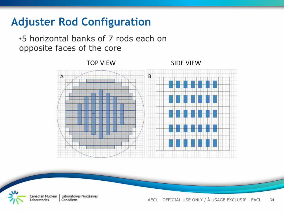
Adjuster Rod Configuration
•5 horizontal banks of 7 rods each on opposite faces of the core
TOP VIEW SIDE VIEW
-35- AECL - OFFICIAL USE ONLY / À USAGE EXCLUSIF - EACL
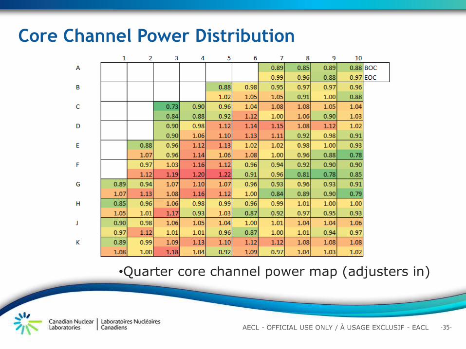
Core Channel Power Distribution
•Quarter core channel power map (adjusters in)
-36- AECL - OFFICIAL USE ONLY / À USAGE EXCLUSIF - EACL
Emergency Liquid Injection Shutdown System
keff decrease by more than 100 mk in less than two seconds
-37- AECL - OFFICIAL USE ONLY / À USAGE EXCLUSIF - EACL
Outline
Introduction
Canadian Supercritical Water Reactor Design
Features
Physics Design and Analysis
Fuel Channel and Material Selection
Thermalhydraulics Analysis
Safety Philosophy for Canadian SCWR
Summary
-38- AECL - OFFICIAL USE ONLY / À USAGE EXCLUSIF - EACL
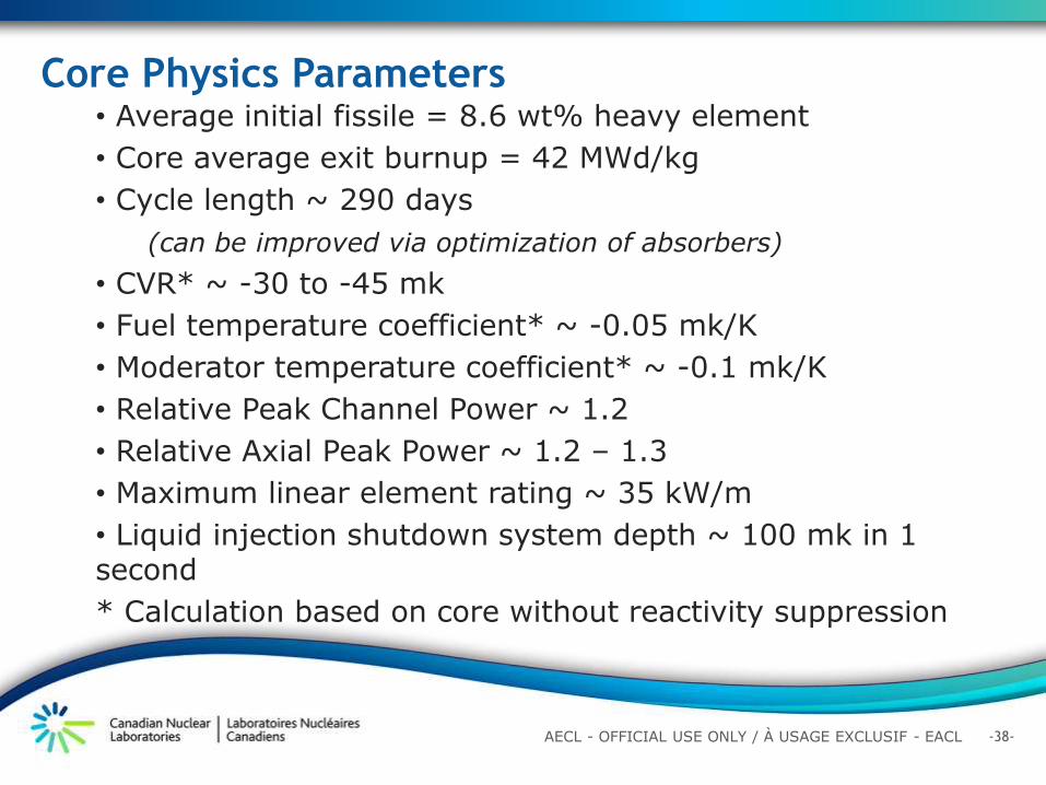
Core Physics Parameters • Average initial fissile = 8.6 wt% heavy element
• Core average exit burnup = 42 MWd/kg
• Cycle length ~ 290 days
(can be improved via optimization of absorbers)
• CVR* ~ -30 to -45 mk
• Fuel temperature coefficient* ~ -0.05 mk/K
• Moderator temperature coefficient* ~ -0.1 mk/K
• Relative Peak Channel Power ~ 1.2
• Relative Axial Peak Power ~ 1.2 – 1.3
• Maximum linear element rating ~ 35 kW/m
• Liquid injection shutdown system depth ~ 100 mk in 1 second
* Calculation based on core without reactivity suppression
-39- AECL - OFFICIAL USE ONLY / À USAGE EXCLUSIF - EACL
• In-core materials should be neutron “transparent”.
• Targeted maximum operating temperatures up to 650oC.
• High strength to retain coolant (pressure tube at 25 MPa).
• Resistance to irradiation induced deformation.
• 75 year life-time operation.
• Separation (seal) between the high-temperature coolant and low-temperature moderator.
• Allowance for single channel replacement.
Requirements of the Canadian SCWR Fuel
Channel
-40- AECL - OFFICIAL USE ONLY / À USAGE EXCLUSIF - EACL
Canadian SCWR Fuel Channel
Fuel Channel Bellows Alloy 625
Welded to the bottom plate of the outlet header which facilitates differential movement between the outlet header and the channel
Pressure Tube Extension Alloy 718
Which connects the pressure tube to the outlet header.
Seal weld between the pressure-tube extension and the inlet plenum which allows coolant to enter into the fuel channel and subsequently to the fuel assembly.
Pressure Tube Excel
-41- AECL - OFFICIAL USE ONLY / À USAGE EXCLUSIF - EACL
Canadian SCWR Fuel Channel
Bellows Pressure tube extension Seal Weld To allow seal welding of the pressure tube to the inlet plenum, the pressure tube transitions from Alloy 718 to zirconium at a point 0.5m above the fuelled region. Excel pressure tube
moderator
tubesheet
Inlet plenum
Outlet header
-42- AECL - OFFICIAL USE ONLY / À USAGE EXCLUSIF - EACL
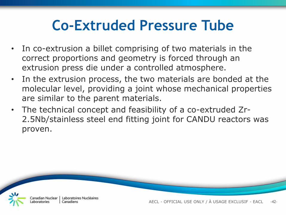
• In co-extrusion a billet comprising of two materials in the correct proportions and geometry is forced through an extrusion press die under a controlled atmosphere.
• In the extrusion process, the two materials are bonded at the molecular level, providing a joint whose mechanical properties are similar to the parent materials.
• The technical concept and feasibility of a co-extruded Zr-2.5Nb/stainless steel end fitting joint for CANDU reactors was proven.
Co-Extruded Pressure Tube
-43- AECL - OFFICIAL USE ONLY / À USAGE EXCLUSIF - EACL
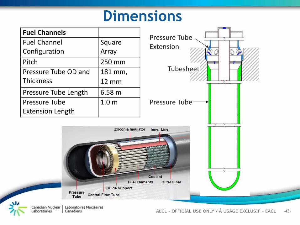
Dimensions Fuel Channels
Fuel Channel Configuration
Square Array
Pitch 250 mm
Pressure Tube OD and Thickness
181 mm,
12 mm
Pressure Tube Length 6.58 m
Pressure Tube Extension Length
1.0 m Pressure Tube
Pressure Tube Extension
Tubesheet
-44- AECL - OFFICIAL USE ONLY / À USAGE EXCLUSIF - EACL
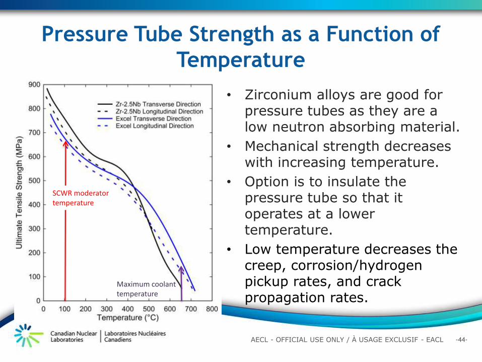
Pressure Tube Strength as a Function of
Temperature
• Zirconium alloys are good for
pressure tubes as they are a low neutron absorbing material.
• Mechanical strength decreases with increasing temperature.
• Option is to insulate the pressure tube so that it operates at a lower temperature.
• Low temperature decreases the creep, corrosion/hydrogen pickup rates, and crack propagation rates.
Maximum coolant temperature
SCWR moderator temperature
-45- AECL - OFFICIAL USE ONLY / À USAGE EXCLUSIF - EACL
The Canadian SCWR fuel channel incorporates concepts from the Re-Entrant Channel (REC) design.
Evolution of the Canadian SCWR Fuel
Channel Concept
REC
Light Water
Coolant Inlet
Inlet Plenum
Outlet Header Head
Outlet Header
Fuel Channels
Calandria Vessel
Fuel Channel
Supports
Light Water
Coolant Outlet
Outflow
Inflow
Liner Tube
Flow Tube
Pressure Tube
Fuel Element
Fuel Element
Flow Tube
Liner Tube
Pressure Tube
Flow Reversal
Inlet Plenum Head
(a) Reactor Core
(b) Cross-Over Piece
(c) Bottom of Fuel Channel
Reactivity Control
Drives
The pressure tube is different from the REC in that an insulator rather than the coolant keeps the pressure tube at a low temperature .
-46- AECL - OFFICIAL USE ONLY / À USAGE EXCLUSIF - EACL
• Each pressure tube is in direct contact with the moderator at 120oC and 150oC.
• The pressure tube is thermally insulated from the hot coolant by an insulator.
• The coolant pressure of 25 MPa is transmitted to the pressure tube.
SCWR Pressure Tube
-47- AECL - OFFICIAL USE ONLY / À USAGE EXCLUSIF - EACL
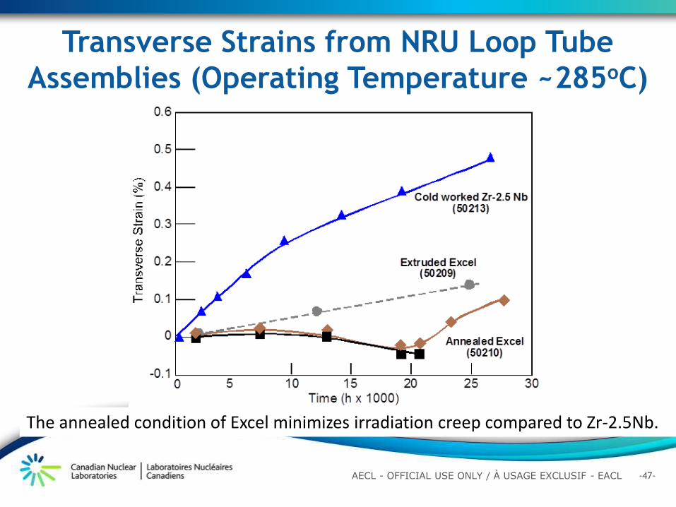
Transverse Strains from NRU Loop Tube
Assemblies (Operating Temperature ~285oC)
The annealed condition of Excel minimizes irradiation creep compared to Zr-2.5Nb.
-48- AECL - OFFICIAL USE ONLY / À USAGE EXCLUSIF - EACL
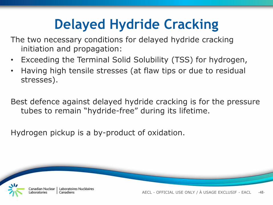
The two necessary conditions for delayed hydride cracking initiation and propagation:
• Exceeding the Terminal Solid Solubility (TSS) for hydrogen,
• Having high tensile stresses (at flaw tips or due to residual stresses).
Best defence against delayed hydride cracking is for the pressure tubes to remain “hydride-free” during its lifetime.
Hydrogen pickup is a by-product of oxidation.
Delayed Hydride Cracking
-49- AECL - OFFICIAL USE ONLY / À USAGE EXCLUSIF - EACL
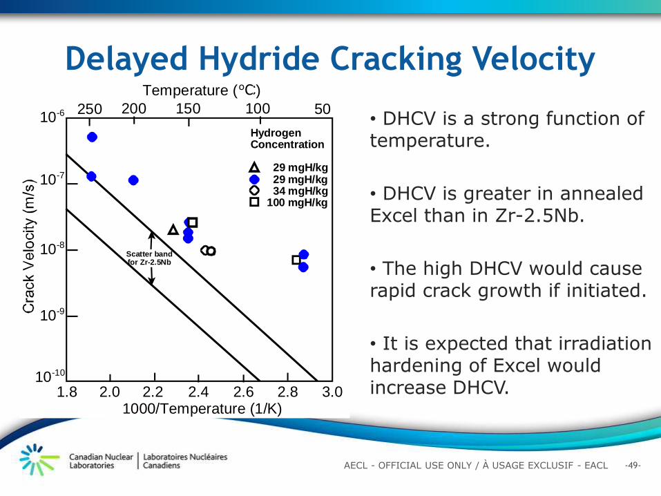
Delayed Hydride Cracking Velocity
• DHCV is a strong function of temperature.
• DHCV is greater in annealed Excel than in Zr-2.5Nb.
• The high DHCV would cause rapid crack growth if initiated.
• It is expected that irradiation hardening of Excel would increase DHCV.
25010-6 150200
1000/Temperature (1/K)
HydrogenConcentration
29 mgH/kg29 mgH/kg34 mgH/kg
100 mgH/kg
50100
Temperature (C)
1.8 2.2 2.4 2.82.0 3.02.6
Scatter bandfor Zr-2.5Nb
10-8
10-9
10-10
10-7
oC
-50- AECL - OFFICIAL USE ONLY / À USAGE EXCLUSIF - EACL
Single Channel Replacement
• The bellows and fuel channel extension are removed by cutting the weld above the pressure tube, and removing this through the outlet header.
• The pressure tube maintains the boundary between the moderator and coolant.
-51- AECL - OFFICIAL USE ONLY / À USAGE EXCLUSIF - EACL
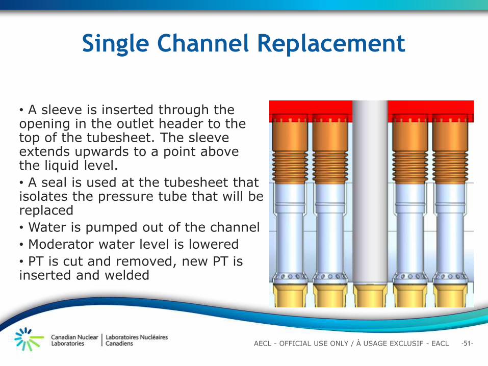
Single Channel Replacement
• A sleeve is inserted through the opening in the outlet header to the top of the tubesheet. The sleeve extends upwards to a point above the liquid level.
• A seal is used at the tubesheet that isolates the pressure tube that will be replaced
• Water is pumped out of the channel
• Moderator water level is lowered
• PT is cut and removed, new PT is inserted and welded
-52- AECL - OFFICIAL USE ONLY / À USAGE EXCLUSIF - EACL
Outline
Introduction
Canadian Supercritical Water Reactor Design
Features
Physics Design and Analysis
Fuel Channel and Material Selection
Thermalhydraulics Analysis
Safety Philosophy for Canadian SCWR
Summary
-53- AECL - OFFICIAL USE ONLY / À USAGE EXCLUSIF - EACL
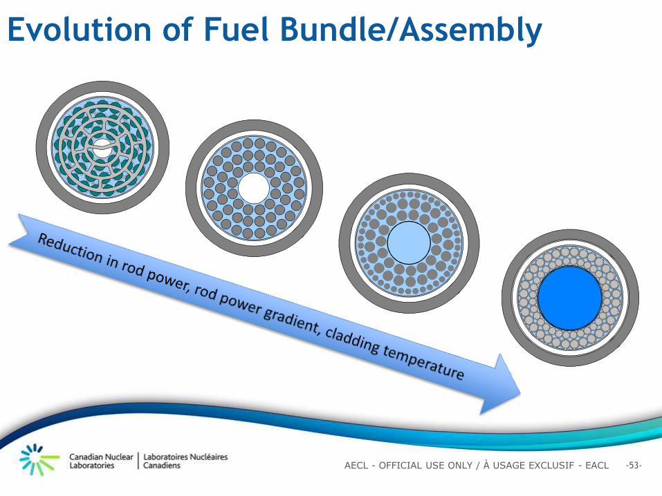
Evolution of Fuel Bundle/Assembly
-54- AECL - OFFICIAL USE ONLY / À USAGE EXCLUSIF - EACL
• Subchannel code (ASSERT) to establish the cladding temperature distributions at normal operating conditions Fully qualified for bundle analyses at sub-critical pressures
Supercritical water properties and heat-transfer correlations implemented
• Computational fluid dynamic (CFD) tool (Star-CCM+) to quantify the effect of wire-wrapped spacers Supercritical water properties implemented Sensitivity of turbulence models and mesh generation assessed
Analytical Tools and Models
-55- AECL - OFFICIAL USE ONLY / À USAGE EXCLUSIF - EACL
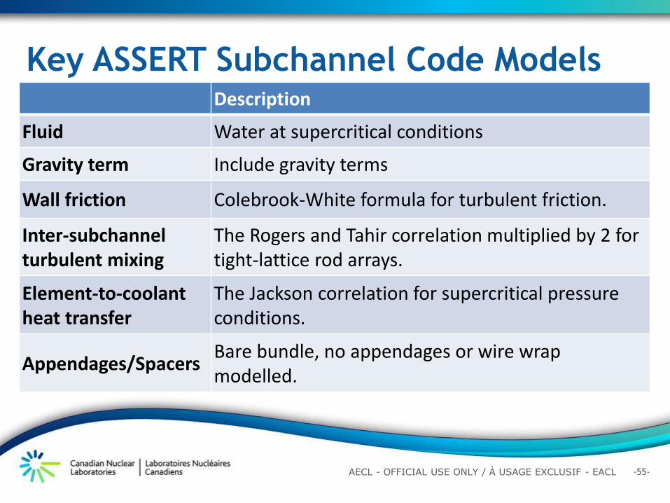
Description
Fluid Water at supercritical conditions
Gravity term Include gravity terms
Wall friction Colebrook-White formula for turbulent friction.
Inter-subchannel turbulent mixing
The Rogers and Tahir correlation multiplied by 2 for tight-lattice rod arrays.
Element-to-coolant heat transfer
The Jackson correlation for supercritical pressure conditions.
Appendages/Spacers Bare bundle, no appendages or wire wrap modelled.
Key ASSERT Subchannel Code Models
-56- AECL - OFFICIAL USE ONLY / À USAGE EXCLUSIF - EACL
-57- AECL - OFFICIAL USE ONLY / À USAGE EXCLUSIF - EACL
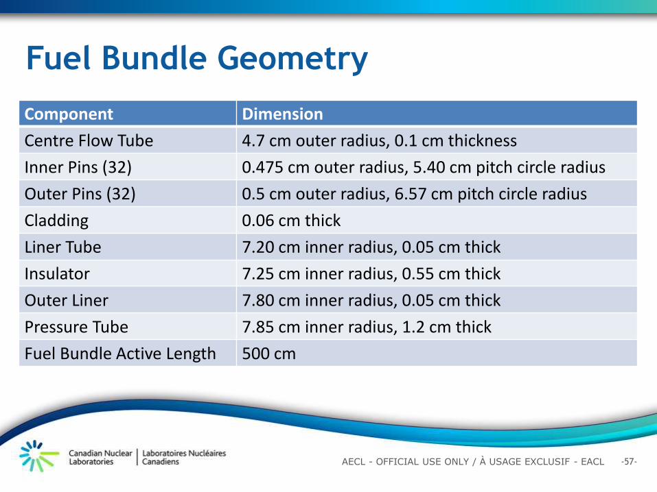
Component Dimension
Centre Flow Tube 4.7 cm outer radius, 0.1 cm thickness
Inner Pins (32) 0.475 cm outer radius, 5.40 cm pitch circle radius
Outer Pins (32) 0.5 cm outer radius, 6.57 cm pitch circle radius
Cladding 0.06 cm thick
Liner Tube 7.20 cm inner radius, 0.05 cm thick
Insulator 7.25 cm inner radius, 0.55 cm thick
Outer Liner 7.80 cm inner radius, 0.05 cm thick
Pressure Tube 7.85 cm inner radius, 1.2 cm thick
Fuel Bundle Active Length 500 cm
Fuel Bundle Geometry
-58- AECL - OFFICIAL USE ONLY / À USAGE EXCLUSIF - EACL
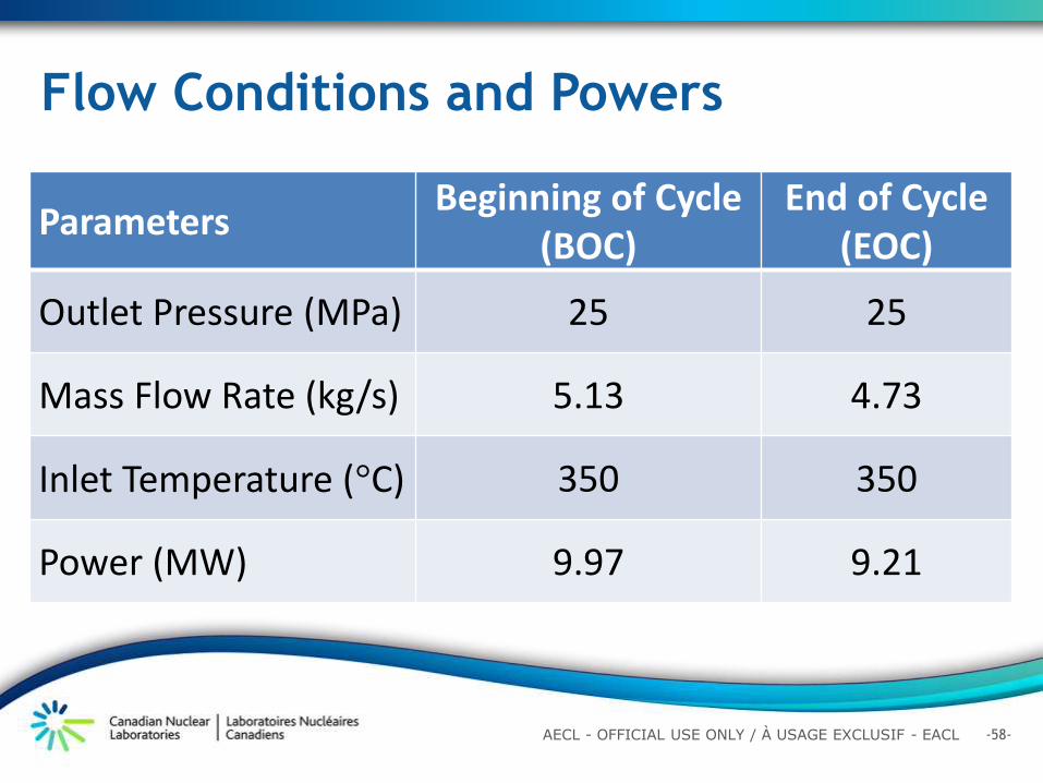
Parameters Beginning of Cycle
(BOC) End of Cycle
(EOC)
Outlet Pressure (MPa) 25 25
Mass Flow Rate (kg/s) 5.13 4.73
Inlet Temperature (°C) 350 350
Power (MW) 9.97 9.21
Flow Conditions and Powers
-59- AECL - OFFICIAL USE ONLY / À USAGE EXCLUSIF - EACL
• Bundle geometry is maintained (no distortion or variation)
• No change in cladding surface conditions • No wire-wrapped spacers and grid spacers at two ends • Negligible heat transfer to the downward inlet flow through the centre tube and to the moderator through the insulator and pressure tube
• Negligible conduction heat transfer through the fuel cladding between subchannels
• Uniform flow conditions at the entrance of the fuel bundle
• Deterioration heat transfer regime is not present in bundle with wire-wrapped spacers.
Key Modelling Assumptions
-60- AECL - OFFICIAL USE ONLY / À USAGE EXCLUSIF - EACL
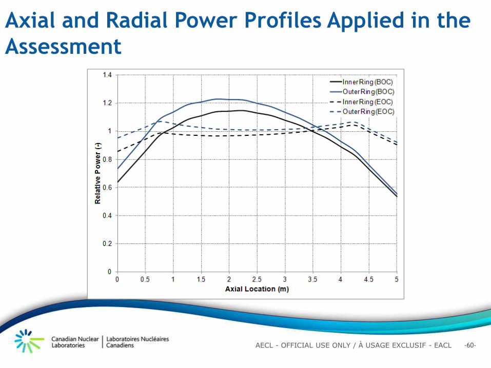
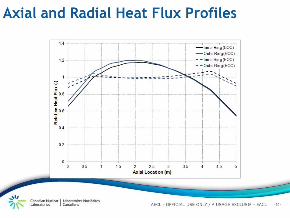
Axial and Radial Power Profiles Applied in the
Assessment
-61- AECL - OFFICIAL USE ONLY / À USAGE EXCLUSIF - EACL
Axial and Radial Heat Flux Profiles
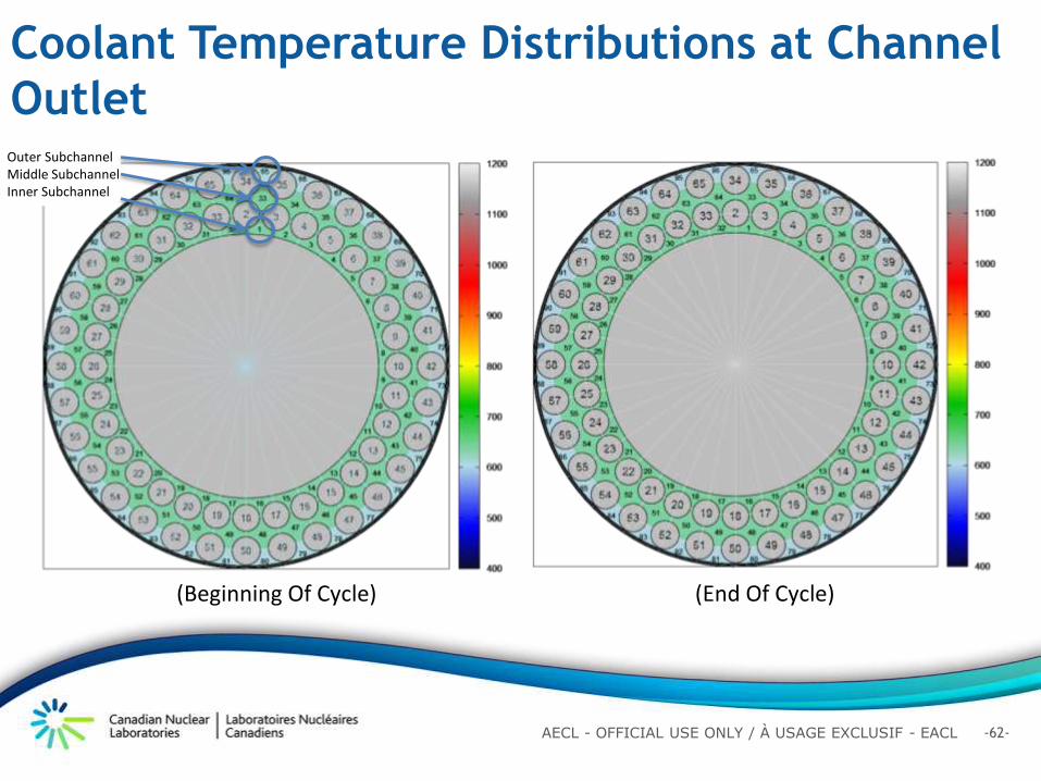
-62- AECL - OFFICIAL USE ONLY / À USAGE EXCLUSIF - EACL
-63- AECL - OFFICIAL USE ONLY / À USAGE EXCLUSIF - EACL
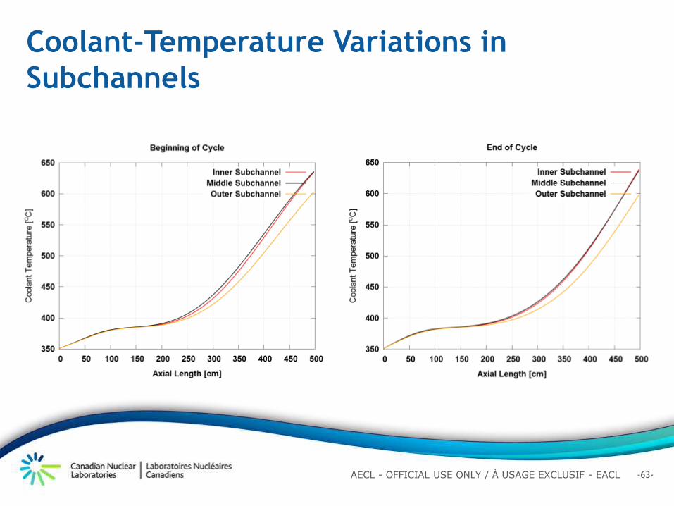
Coolant-Temperature Variations in
Subchannels
-64- AECL - OFFICIAL USE ONLY / À USAGE EXCLUSIF - EACL
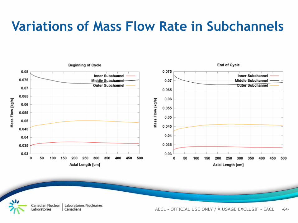
Variations of Mass Flow Rate in Subchannels
-65- AECL - OFFICIAL USE ONLY / À USAGE EXCLUSIF - EACL
Cladding-Temperature Variations in
Subchannels
808 °C
-66- AECL - OFFICIAL USE ONLY / À USAGE EXCLUSIF - EACL
• Subchannel analysis focused on bare bundle only (i.e., no spacers)
• Wire-wrapped spacers have been incorporated to maintain gap sizes between rods and minimize vibration
• Previous studies demonstrated enhancement effect of wire-wrapped spacers on heat transfer leading to cladding temperature reduction in tubes, annuli and bundle subassembly Current subchannel analysis would
overpredict the cladding temperature (hence conservative)
• Confirmatory analysis for SCWR fuel assembly using a CFD tool
Effect of Wire-Wrapped Spacers
-67- AECL - OFFICIAL USE ONLY / À USAGE EXCLUSIF - EACL
•Low Reynolds y+ k-ω turbulence model
The first node point set to a corresponding wall y+ value of ~1
•Variable fluid properties
Star-CCM+ CFD Tool Models
-68- AECL - OFFICIAL USE ONLY / À USAGE EXCLUSIF - EACL
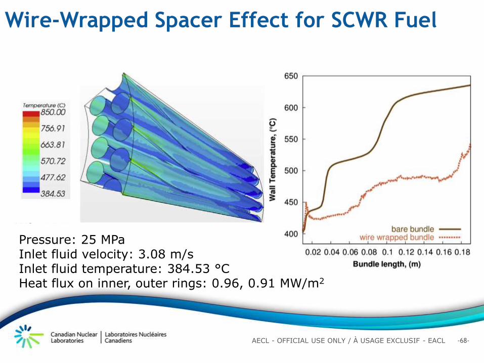
Wire-Wrapped Spacer Effect for SCWR Fuel
Pressure: 25 MPa Inlet fluid velocity: 3.08 m/s Inlet fluid temperature: 384.53 °C Heat flux on inner, outer rings: 0.96, 0.91 MW/m2
-69- AECL - OFFICIAL USE ONLY / À USAGE EXCLUSIF - EACL
• Power profiles for a device free core without burnable neutron absorber (BNA) were applied in the analysis
• Power profiles for a core with BNA and adjuster rods are different Local powers at the peak
temperature locations are lower Peak cladding temperatures are
anticipated to be lower Current predicted peak cladding
temperature is conservative
Changes in Axial Power Profiles
Core with BNA and Adjuster Rods (BOC)Core with BNA and Adjuster Rods (EOC)
-70- AECL - OFFICIAL USE ONLY / À USAGE EXCLUSIF - EACL
Outline
Introduction
Canadian Supercritical Water Reactor Design
Features
Physics Design and Analysis
Fuel Channel and Material Selection
Thermalhydraulics Analysis
Safety Philosophy for Canadian SCWR
Summary
-71- AECL - OFFICIAL USE ONLY / À USAGE EXCLUSIF - EACL
Safety Philosophy for Canadian SCWR
Safety advances are made possible through:
Adoption of ambitious safety objectives to drive research
Continued emphasis on principle of “defense-in-depth”
Systematic application of an integrated safety approach,
both deterministic and probabilistic, to ensure that safety
is “built in” rather than “added on”
-72- AECL - OFFICIAL USE ONLY / À USAGE EXCLUSIF - EACL
Integrated Safety Assessment Methodology
Five practical and flexible tools to identify
vulnerabilities and relative contributions to risk
commensurate with design maturity
-73- AECL - OFFICIAL USE ONLY / À USAGE EXCLUSIF - EACL
Completed QSR , PIRT, and PSA to assess the
Risk & Safety of CSCWR – the three most appropriate tools
applicable to a Conceptual Design
Integrated Safety Assessment Methodology
-74- AECL - OFFICIAL USE ONLY / À USAGE EXCLUSIF - EACL
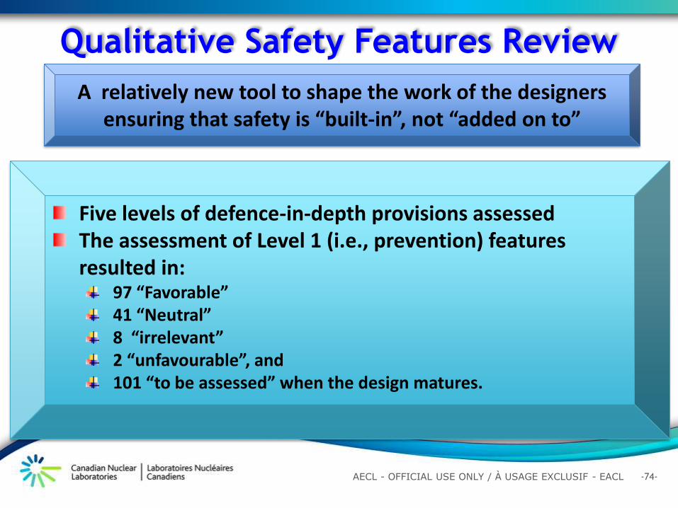
Qualitative Safety Features Review
A relatively new tool to shape the work of the designers ensuring that safety is “built-in”, not “added on to”
Five levels of defence-in-depth provisions assessed The assessment of Level 1 (i.e., prevention) features resulted in:
97 “Favorable” 41 “Neutral” 8 “irrelevant” 2 “unfavourable”, and 101 “to be assessed” when the design matures.
-75- AECL - OFFICIAL USE ONLY / À USAGE EXCLUSIF - EACL
A Sample QSR Assessment Table
Index Content of Recommendation QSR Team Comments Qualitative
Assessment
1.1
Work out and set up a design
for the plant (i.e., the reactor
core, primary circuits and
balance-of-plant (BOP), that will
allow simple procedures for
the reactor operations and
maintenance during normal
conditions (i.e., minimize
process complexity and avoid
inherent instability; systematic
consideration of human factors
and the human–machine
interface for operation and shut
down).
Majority of the reactor core transport system and feedwater
circuit calculation for concept design is complete (Matt). Favourable
Plant energy balance has been completed (Matt) Favourable