Concepts and Theory • Information can be transmitted by varying some physical property of a signal. – Voltage – Current – Intensity – Magnetic Orientation • Usually the information is transmitted as an electric signal.
Transcript
Concepts and Theory
• Information can be transmitted by varying some physical property of a signal.– Voltage– Current– Intensity– Magnetic Orientation
• Usually the information is transmitted as an electric signal.
Direct Current
• An electric current is called direct current if the electrons are always flowing in the same direction.
• Direct current can be either continuous or intermittent
5v
0v
Alternating Current
• An alternating voltage reverses its polarity, which produces current that reverses its direction.
• In the US, house current is 120 volts AC.
Periodic Waves
Amplitude
Cycle Cycle Cycle
• The frequency of a periodic wave, measured in hertz (Hz), is the number of cycles that occur per second
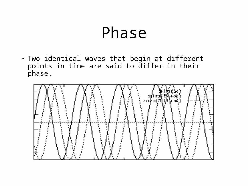
Phase
• Two identical waves that begin at different points in time are said to differ in their phase.
Fourier Analysis
• Any reasonably behaved periodic function, g(t), with period T can be constructed by summing a (possibly infinite) number of sines and cosines:
)2cos()2sin(2
1)(
11nfbnftactg
nn
nn
Where f=1/T is the fundamental frequency and an and bn are the sine and cosine amplitudes of the nth harmonics (terms)
Fourier in Practice
• Say you wanted to send the following signal
1 0 1 1 0 0 0 1 0 1
Components of a Digital Signal
Components of a Digital Signal
Components of a Digital Signal
Components of a Digital Signal
Components of a Digital Signal
How does this affect communication?
• No transmission facility can transmit signals without loosing some power in the process.
• If all Fourier components were equally diminished, the resulting signal would be reduced in amplitude but not distorted.
• Usually, the amplitudes are transmitted undiminished from 0 up to some frequency fc with all frequencies above the cutoff strongly attenuated.
Communication over a telephone
• An ordinary telephone line has an artificially introduced cutoff frequency near 3000Hz.
• If we transmit digital data at a rate of b bits/sec, the time required to send 8 bits is 8/b seconds, so the frequency of the first harmonic is b/8Hz.
• This means on a telephone line the number of the highest harmonic passed through is 3000/(b/8) or 24,000/b.
Data Rates and Harmonics
Bps T (msec) First Harmonic (Hz) Harmonics Sent300 26.67 37.5 80600 13.33 75 40
• The speed at which analog transmissions take place is usually measured in terms of BAUD.
• The BAUD rate is the rate of signaling changes per second on a channel. The BAUD rate does not have to equal the bit rate.
• Based on the Fourier analysis of a voice grade telephone line the highest BAUD rate that can be used is 2400 BAUD.
Multi-Level Encoding
• Multi-level encoding sends several bits in a single signal unit.
Red00
Green01
Blue10
White11
Multi-Level Encoding
01
00
10
11
Signal Changes
10 00 11 01 Bit Stream
Multi-Level EncodingBits Encoded Modulation Rate
(Bauds)Bits Transmitted
1 2400 2400
2 2400 4800
3 2400 7200
4 2400 9600
5 2400 1200
6 2400 14400
8 2400 192006
Bandwidth
• Bandwidth: the information carrying capability of a channel.
• The bandwidth for a given transmission medium is fixed.
• Different mediums have different bandwidths.• “never underestimate the bandwidth of a station
wagon full of tapes hurtling down the highway.”
Bandwidth
Ball size represents the Data Rate
LOW SPEED HIGH SPEED
Box size represents the Bandwidth
Analog Transmission
• Analog transmission has dominated all communication for the past 100 years.
• Even though long-distance trunks are now digital, the local loop is still analog and will probably stay that way for a long time.
• So when a computer uses a telephone to send data, the data must be converted to analog form for transmission.
Modems
• A device that converts digital data into a modulated analog carrier signal that can be sent over analog transmission lines is called a modem.
• MODEM stands for MOdulator/DEmodulator.• Modulation refers to the process of superimposing
digital data onto an analog carrier signal.• Demodulation refers to the process of recovering
the digital data from the modulated carrier.
THE DTE/DCE Interface
DTE
DCE
The DTE/DCE Interface
• DTE - Data Terminal Equipment– typically an end-user device– supports end-user applications
• DCE - Data Communications Equipment– connects the DTE into the communications
circuit
• The data communications path is the physical path between the DCEs.
Digital to Analog Conversion
• Three basic methods of digital-to-analog modulation exist– amplitude
– frequency
– phase
• The modulation techniques superimpose data onto a carrier signal– a carrier signal is a signal with known properties
Amplitude Modulation
• AM modems alter the carrier signal’s amplitude.
• In its simplest form, the carrier is switched on and off to represent the binary state.
• AM modulation is not often used because of power and signal distortion problems.
Frequency Modulation
• FM changes the frequency of the carrier in accordance with the digital bit stream.
• The most common form of FM modulation is frequency shift key (FSK) which uses 4 frequencies within the telephone line bandwidth:– 1070/1270Hz represent 0 (space)
– 2025/2225Hz represent 1 (mark)
• FSK was widely used in low-speed modems.
Phase Modulation
• Phase modulation is used almost exclusively on high speed modems
• The phase modulation method is also called phase shift keying (PSK).
• PSK can be used to provide multi-level encoding: Data Phase Shift
11 4510 13501 22500 315
PSK
4PSK4800bps
4PSK4800 bps
8PSK7200bps
0180
9090
0180
270 270
45 45135 135
225 225315 315
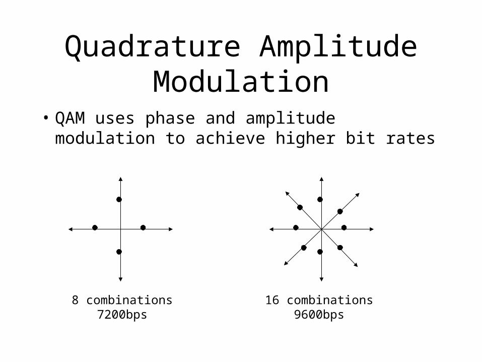
Quadrature Amplitude Modulation
• QAM uses phase and amplitude modulation to achieve higher bit rates
8 combinations7200bps
16 combinations9600bps
Speed, I want speed!!!
• So we are now up to 9600bps, can we go faster?• The next step up is 14400bps. This can be
achieved by transmitting 6 bits per sample. Its constellation pattern has 64 points.
• At these speeds small amounts of noise can cause big problems.
• Many modems add a parity bit, the points are then coded to minimize error. This is called trellis coding.
Transmission Media
• Transmission media refers to the way in which two computers are connected.
• A wide variety of media exists, but they fall into two main classes:– Bounded: the data is confined to specific pathways.
Common examples include wire and fiber optic cable.
– Unbounded: transmit the data carrying signal through space. Broadcast radio and television are examples of unbounded media.
Bounded Media
• Some important characteristics of cable include:– Resistance to EMI
– Bandwidth
– Attenuation (how the cable reduces the strength of the signal with distance)
– Cost
– Installation
– Maintenance
Twisted Pair
• A twisted pair consists of two insulated wires twisted together in a helical form.
• The purpose of twisting the wires is to reduce electrical interference from similar pairs close by.
• The most common application of twisted pair is the telephone system.
• The bandwidth of the pair depends on the thickness of the wire and the distance traveled.
Types of Twisted Pair Cabling
• Twisted pair comes in several varieties, two of which are important for networking– Category 3 consists of two insulated wires twisted
together. Four such pairs are typically grouped together in a plastic sheath.
– Category 5 cabling has more twists per centimeter and uses Teflon insulation. This results in less crosstalk and a better quality signal over long distances.
• Both of these wiring types are usually called UTP (unshielded twisted pair).
Twisted Pair Summary
• Advantages– telephone cable standards are mature
– Materials are plentiful and easy to work with.
– It may be possible to use existing wiring
– UTP is the lowest cost cabling
• Disadvantages– STP is expensive and hard to work with
– TP is sensitive to EMI
– International standards for some uses do not exist.
Coaxial Cable
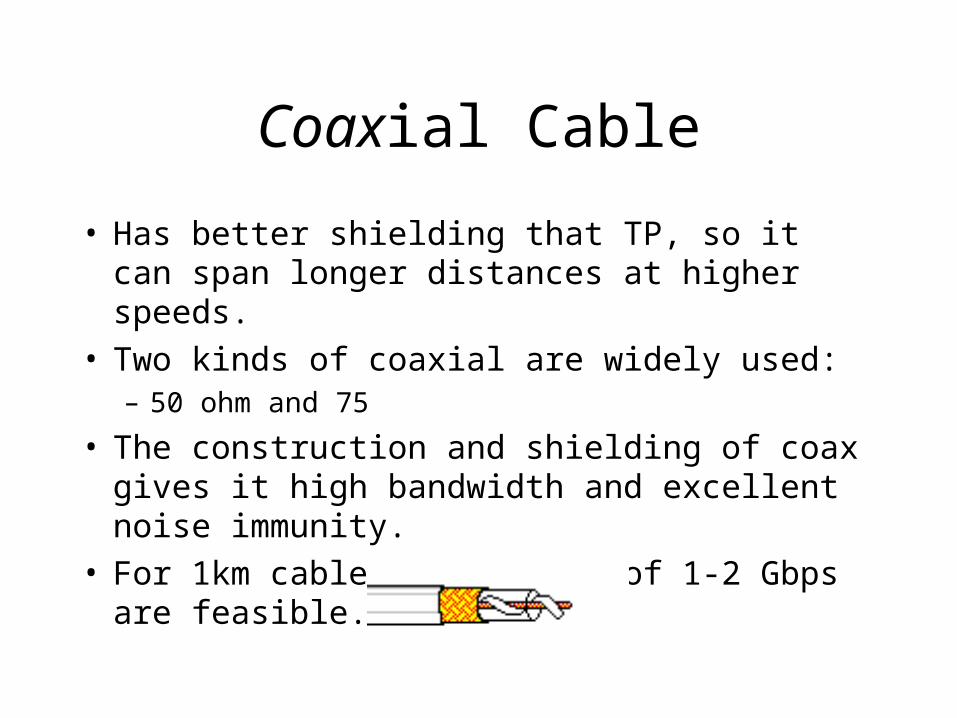
• Has better shielding that TP, so it can span longer distances at higher speeds.
• Two kinds of coaxial are widely used:– 50 ohm and 75
• The construction and shielding of coax gives it high bandwidth and excellent noise immunity.
• For 1km cables data rates of 1-2 Gbps are feasible.
Types of Coaxial Cable
• A wide variety of coaxial cable is available:– RG-8 and RG-11 are 50 ohm cables used for
thickwire Ethernet (10base5)– RG-58 is a smaller 50 ohm cable used with
thinwire (cheaper-net) Ethernet (10base2).– RG-59 is a 75 ohm cable used to wire cable TV
and is used in some token ring networks.– RG-62 is a 93 ohm cable used for ARCnet.
Types of Coaxial Cable
• In addition to impedance the cables may differ in the type of center conductor:– solid copper
– twisted
• The coating used on most coaxial cables is PVC which cannot be used in some situations. It is possible to get Teflon coated coaxial cable which is referred to as plenum.
Broadband Coaxial Cable
• The broadband coaxial cable system uses analog transmission on standard cable television cabling.
• Broadband:– Telephone world: anything with a bandwidth greater
than 4Khz.
– Computer world: any cable using analog transmission.
• Because analog transmission is being used bandwidths up to 300Mhz that can run for nearly 100km.
Broadband Coaxial Cable
• Broadband systems are divided into multiple channels, frequently the 6Mhz channels used for television broadcasting.
• Broadband systems typically need analog amplifiers to boost the signal periodically. The amplifiers can transmit in one direction only.
• This results in two types of broadband systems:– dual cable– single cable
Coaxial Cable Summary
• Advantages:– Good resistance to EMI
– High Bandwidth
– Capable of withstanding harsh environments
– Very mature technology
– Easy to install
• Disadvantages– Bulky
– Expensive
Fiber Optics
• An optical transmission system consists of three components:– light source– transmission medium– detector
• Conventionally, a pulse of light indicates a 1-bit and the absence of light indicates a 0-bit.
Fiber Cable Summary
• Advantages– High bandwidth– Immune to EMI– No RF emissions
• Disadvantages– Expensive
Cable CharacteristicsCableType
CableCost
Installation Cost EMI Sensitivity Bandwidth
UTP Lowest Lowest (mayalready be in place)
Highest Lowest
STP Medium Moderate Low Moderate
Coaxial Medium Moderate Low High
Fiber Highest Highest None Very High
Unbounded Media
• Broadcasting data signals through space.• Advantages
– Easy to relocate equipment– Mobility– Cost effective in certain circumstances
• Radio frequencies extend from the KHz range, through the MHz range, and into the low GHz range.
• Radio transmissions can extend beyond line of sight communication.
• Radio signals are usually broadcast on a wide beam and are an effective way to transmit to a large number of receivers.
Radio Transmission
• Advantages– Easy to generate
– Can travel long distances
– Penetrate buildings easily
– Omnidirectional
• Disadvantages– Few frequencies are available
– Noise and interference
– Limited bandwidth
Microwave Transmission
• Microwaves have frequencies that extend into the GHz range.
• At this frequency, the waves travel in straight lines and can be narrowly focused– concentrating the beam gives a higher signal to noise
ratio
– sender and receiving antennas must be accurately aligned.
• Microwave Communications Inc.
Microwave Summary
• Advantages– High Bandwidth
– Relatively Inexpensive
– Some Bands do not need licensing
• Disadvantages– Shortage of spectrum
– Absorption by water (8GHz and higher)
– Line of sight
– Multipath fading
Infrared
• Advantages– Relatively directional– Cheap– Easy to Build
• Disadvantages– Short distances– Do not pass through solid objects (+ and -)
Unbounded MediaMedia Coverage EMI Sensitivity
TerrestrialMicrowave
Narrow beam Moderate
SatelliteMicrowave
Narrow or broadbeam
Moderate
Radio Broad Beam High
Laser Very Narrow None
Infrared Narrow or broadbeam
None
Multiplexing
• It is often the case that the bandwidth provided by a channel must be shared.
• Multiplexing– combining multiple data channels onto a single
medium; user data are interleaved on a bit, byte, or block basis (time division) or separated by different carrier frequencies (frequency division).
• It is often cheaper to run one big bandwidth cable than several cables of smaller bandwidth.
Frequency Division Multiplexing
• The frequency channel is divided into logical channels, with each having exclusive use of some frequency band– AM/FM radio
– Cable TV
60 64 68 72
Time Division Multiplexing
• The logical channels take turns using the the transmission medium. Each one, in a round robin fashion, periodically gets the entire bandwidth for a short period of time.– Timesharing computers– Chess Master– Music/Ads on a radio station
• Lets look at TDM in the phone system.
TDM
• TDM is used to combine 64Kbps digital voice streams to form higher bandwidth streams.
• A synchronous TDM has n identical input links and one output link that is at least n times as fast.
• The multiplexor buffers incoming bits and places them, in turn, on the output line.
• Each set of n output samples, along with some additional overhead bits, constitutes a frame.
The T1 Carrier
• The T1 carrier consists of 24 input channels multiplexed together.
• Each channel, in turn, gets to insert 8 bits into the output stream (7 data, 1 control).
193 Bit Frame (125sec)
……..
Channel 1 Channel 2 Channel 3 Channel 24
Data
ControlFraming
Switching
• The telephone system can be divided into two parts:– outside plant (local loops, trunks, …)– inside plant (the switches)
• A switch is responsible for finding a path between two channels
• Two switching techniques are used:– circuit switching– packet switching
Circuit Switching
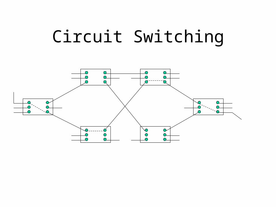
• When using circuit switching, the switching equipment seeks out a physical path.
• An important property of circuit switching is that an end-to-end path must be established before data can be sent.
• Circuit switching typically has three phases:– circuit establishment– data transfer– circuit breakdown
Circuit Switching
Advantages of Circuit Switching
• Advantages– once circuit is established only delay for data is
the propagation time for the signal.– fixed/known bandwidth– no danger of congestion
Message Switching
• No physical path is established, instead the communication is broken down into blocks. The blocks are then routed through the network independently.
• This type of network is often referred to as a store and forward network.
• Message switching does not limit the block size.
Message Switching
Packet Switching
• Some problems with message switching:– large messages may tie up lines for a long period of
time.
– Amount of memory required at switches for buffers.
• Packet switching limits the size of the messages• Packet switched networks are well suited to
handling interactive traffic.
Circuit vs. Packet SwitchingItem Circuit-
SwitchedPacket-switched
Dedicated path Yes NoBandwidth available Fixed DynamicPotentially wasted bandwidth Yes NoStore-and-forward transmission No YesEach packet follows same route Yes NoCall setup Yes No*When can congestion occur At setup On every packetWhen routing occurs At setup On every packetCharging Per minute Per packet