Concepts in Imaging and Microscopy Imaging Membrane Potential With Voltage-Sensitive Dyes MICHAL ZOCHOWSKI, 1, * MATT WACHOWIAK, 1 CHUN X. FALK, 2 LAWRENCE B. COHEN, 1,2 YING-WAN LAM, 1 SRDJAN ANTIC, 1 AND DEJAN ZECEVIC 1 1 Department of Cellular and Molecular Physiology, Yale University School of Medicine New Haven, Connecticut 06520; and 2 RedShirtImaging, LLC, Fairfield, Connecticut 06432 Abstract. Membrane potential can be measured optically using a variety of molecular probes. These measurements can be useful in studying function at the level of an indi- vidual cell, for determining how groups of neurons generate a behavior, and for studying the correlated behavior of populations of neurons. Examples of the three kinds of measurements are presented. The signals obtained from these measurements are generally small. Methodological considerations necessary to optimize the resulting signal-to- noise ratio are discussed. Introduction An optical measurement of membrane potential using a molecular probe can be beneficial in a variety of circum- stances. One advantage is the ability to measure from many locations simultaneously. This is especially important in the study of nervous systems in which many parts of an indi- vidual cell, or many cells, or many regions of the nervous system are active at the same time. In addition, optical recording offers the possibility of recording from processes that are too small or fragile for electrode recording. Several optical properties of membrane-bound dyes are sensitive to membrane potential, including fluorescence, absorption, dichroism, birefringence, fluorescence reso- nance energy transfer, nonlinear second harmonic genera- tion, and resonance Raman absorption. However, because the vast majority of applications have involved fluorescence or absorption, these will be emphasized in this review. All of the optical signals described here are “fast” signals (Co- hen and Salzberg, 1978) that are presumed to arise from membrane-bound dye; they follow changes in membrane potential with time courses that are rapid compared to the rise time of an action potential. Studies of the molecular mechanisms that result in po- tential-dependent optical properties have produced evidence supporting three mechanisms (for different dyes): dipole rotation, electrochromism, and a potential-sensitive mono- mer-dimer equilibrium. Dye mechanisms are discussed in Waggoner and Grinvald (1977), Loew et al. (1985), and Fromherz et al. (1991). We begin with examples of results obtained from mea- surements addressing three quite different neurobiological problems. In all three instances the camera was a photo- diode array with only 464 pixels (NeuroPlex; RedShirt- Imaging, LLC, Fairfield, CT). Despite this low spatial res- olution, the camera resolution was not limiting in any of the examples. On the positive side, this camera has an outstand- ing dynamic range; with an incident intensity of more than 10 10 photons per frame, it measures signals that are a fractional change (DI/I) of one part in 10 5 . In addition, it has a frame rate of 1.6 kHz (fast enough to measure most neurobiologically important signals). On the other hand, recently introduced CCD cameras not only have similar frame rates but also have lower dark noise. Thus, in one of the three measurements, we think that improved signal-to- noise ratios could be obtained with a cooled CCD camera. The optical signals in the example measurements are not large—they represent fractional changes in light intensity (DI/I) of from 10 24 to 3 3 10 22 . Nonetheless, they can be measured with an acceptable signal-to-noise ratio after at- tention to details of the measurement that are described in the second part of the paper. Figure 1 illustrates three qualitatively different areas of neurobiology in which imaging membrane potential has been useful. First (left panel), to know how a neuron inte- grates its synaptic input into its action potential output, one must be able to measure membrane potential wherever synaptic input occurs and at the places where spikes are initiated. Second (middle panel), to understand how a ner- vous system generates a behavior, the action potential ac- tivity of many (all) of the participating neurons must be Received 22 June 1999; accepted 19 October 1999. * To whom correspondence should be addressed. E-mail: mrz@ fred.med.yale.edu This is the fourth in a series of articles entitled “Concepts in Imaging and Microscopy.” This series is supported by the Optical Imaging Association (OPIA) and was introduced with an editorial in the April 1998 issue of this journal (Biol. Bull. 194: 99). Other articles in the series are listed on The Biological Bulletin’s website at http://www.mbl.edu/html/BB/home. BB.html. Reference: Biol. Bull. 198: 1–21. (February 2000) 1
Transcript
Concepts in Imaging and Microscopy
Imaging Membrane Potential With Voltage-Sensitive Dyes
MICHAL ZOCHOWSKI,1,* MATT WACHOWIAK, 1 CHUN X. FALK,2 LAWRENCE B. COHEN,1,2
YING-WAN LAM, 1 SRDJAN ANTIC,1 AND DEJAN ZECEVIC1
1 Department of Cellular and Molecular Physiology, Yale University School of Medicine New Haven, Connecticut06520; and2 RedShirtImaging, LLC, Fairfield, Connecticut 06432
Abstract. Membrane potential can be measured opticallyusing a variety of molecular probes. These measurementscan be useful in studying function at the level of an indi-vidual cell, for determining how groups of neurons generatea behavior, and for studying the correlated behavior ofpopulations of neurons. Examples of the three kinds ofmeasurements are presented. The signals obtained fromthese measurements are generally small. Methodologicalconsiderations necessary to optimize the resulting signal-to-noise ratio are discussed.
Introduction
An optical measurement of membrane potential using amolecular probe can be beneficial in a variety of circum-stances. One advantage is the ability to measure from manylocations simultaneously. This is especially important in thestudy of nervous systems in which many parts of an indi-vidual cell, or many cells, or many regions of the nervoussystem are active at the same time. In addition, opticalrecording offers the possibility of recording from processesthat are too small or fragile for electrode recording.
Several optical properties of membrane-bound dyes aresensitive to membrane potential, including fluorescence,absorption, dichroism, birefringence, fluorescence reso-nance energy transfer, nonlinear second harmonic genera-tion, and resonance Raman absorption. However, becausethe vast majority of applications have involved fluorescenceor absorption, these will be emphasized in this review. Allof the optical signals described here are “fast” signals (Co-hen and Salzberg, 1978) that are presumed to arise frommembrane-bound dye; they follow changes in membrane
potential with time courses that are rapid compared to therise time of an action potential.
Studies of the molecular mechanisms that result in po-tential-dependent optical properties have produced evidencesupporting three mechanisms (for different dyes): dipolerotation, electrochromism, and a potential-sensitive mono-mer-dimer equilibrium. Dye mechanisms are discussed inWaggoner and Grinvald (1977), Loewet al. (1985), andFromherzet al. (1991).
We begin with examples of results obtained from mea-surements addressing three quite different neurobiologicalproblems. In all three instances the camera was a photo-diode array with only 464 pixels (NeuroPlex; RedShirt-Imaging, LLC, Fairfield, CT). Despite this low spatial res-olution, the camera resolution was not limiting in any of theexamples. On the positive side, this camera has an outstand-ing dynamic range; with an incident intensity of more than1010 photons per frame, it measures signals that are afractional change (DI/I) of one part in 105. In addition, it hasa frame rate of 1.6 kHz (fast enough to measure mostneurobiologically important signals). On the other hand,recently introduced CCD cameras not only have similarframe rates but also have lower dark noise. Thus, in one ofthe three measurements, we think that improved signal-to-noise ratios could be obtained with a cooled CCD camera.The optical signals in the example measurements are notlarge—they represent fractional changes in light intensity(DI/I) of from 1024 to 3 3 1022. Nonetheless, they can bemeasured with an acceptable signal-to-noise ratio after at-tention to details of the measurement that are described inthe second part of the paper.
Figure 1 illustrates three qualitatively different areas ofneurobiology in which imaging membrane potential hasbeen useful. First (left panel), to know how a neuron inte-grates its synaptic input into its action potential output, onemust be able to measure membrane potential whereversynaptic input occurs and at the places where spikes areinitiated. Second (middle panel), to understand how a ner-vous system generates a behavior, the action potential ac-tivity of many (all) of the participating neurons must be
Received 22 June 1999; accepted 19 October 1999.* To whom correspondence should be addressed. E-mail: mrz@
fred.med.yale.eduThis is the fourth in a series of articles entitled “Concepts in Imaging and
Microscopy.” This series is supported by the Optical Imaging Association(OPIA) and was introduced with an editorial in the April 1998 issue of thisjournal (Biol. Bull. 194: 99). Other articles in the series are listed onTheBiological Bulletin’s website at http://www.mbl.edu/html/BB/home.BB.html.
Reference:Biol. Bull. 198: 1–21. (February 2000)
1
measured simultaneously. Third (right panel), responses tosensory stimuli and generation of motor output in the ver-tebrate brain are often accompanied by synchronous activa-tion of many neurons in widespread brain areas; voltage-sensitive dye recordings allow simultaneous measurementof population signals from many areas. In these three in-stances, optical recordings have provided kinds of informa-tion about the function of the nervous system that werepreviously unobtainable.
In the second half of the article, we describe the experi-mental details that are important in obtaining the signal-to-noise ratios achieved in the experiments described in thefirst section. We discuss signal type, dyes, light sources,photodetectors, and optics.
Three Examples
1. Processes of an individual neuron (Fig. 1, left panel)
Understanding the biophysical properties of single neu-rons and how they process information is fundamental tounderstanding how the brain works. With the developmentof new measuring techniques that allow more direct inves-
tigation of individual nerve cells, it became widely recog-nized, especially during the last 20 years, that dendriticmembranes of many vertebrate CNS neurons contain activeconductances such as voltage-activated Na1, Ca21, and K1
channels (e.g.,Stuart and Sakmann, 1994; Sprustonet al.,1995; Magee and Johnston, 1995; Mageeet al., 1995). Animportant consequence of active dendrites is that regionalelectrical properties of branching neuronal processes will beextraordinarily complex, dynamic, and, in the general case,impossible to predict in the absence of detailed measure-ments.
To obtain such a measurement one would, ideally, like tomonitor, at multiple sites, subthreshold events as they travelfrom the sites of origin on neuronal processes and summateat particular locations to influence the initiation of actionpotentials. This goal has not been achieved in any neuron,vertebrate or invertebrate, due to the technical limitations ofmeasurements that employ electrodes. Better spatial resolu-tion necessitates a turn from direct electrical recording toindirect, optical measurements using voltage-sensitive dyes.Recently, the sensitivity of intracellular voltage-sensitivedye techniques for monitoring neuronal processesin situhas
Figure 1. Schematic of the three kinds of measurements described as examples. (Left) An individual corticalhippocampal CA1 pyramidal cell. Each pixel of the 464-element photodiode array receives light from a smallpart of the dendrite, axon, or cell body of the neuron. An optical measurement of membrane potential providesinformation about how the neuron converts its synaptic input into its spike output. (Middle) A slice through aninvertebrate ganglion with its cell bodies in a cortex around the outside and neuropil in the middle. Here eachdetector receives light from one or a small number of cell bodies. A voltage-sensitive dye measurement of spikeactivity while the ganglion is generating a behavior provides information about how the behavior is generated.(Right) A vertebrate brain with the superimposed 464-element photodiode array (used in all three examples).Each pixel of the array receives light from thousands of cells and processes. The signal is the population averageof the change in membrane potential in those cells and processes. The image of the hippocampal neuron wastaken from Mainenet al. (1996).
2 M. ZOCHOWSKI ET AL.
been improved by a factor of roughly 150, allowing directrecording of subthreshold and action potential signals fromthe neurites of invertebrate neurons (Antic and Zecevic,1995; Zecevic, 1996). The improvement in the signal-to-noise ratio is based on previous experience from otherlaboratories (Davilaet al.,1974; Grinvaldet al.,1987) andon (1) finding an intracellular dye that provides a relativelylarge fractional change in fluorescence and (2) improve-ments in the apparatus to increase the incident light inten-
sity, to lower the noise, and to filter more efficiently. En-couraging results have also been obtained in initial studieson vertebrate CNS neurons in brain slices (see below).
An invertebrate neuron.A typical result of a multi-sitevoltage-sensitive dye recording is shown in Figure 2. Thefluorescent image of a metacerebralHelix neuron follow-ing injection with the fluorescent voltage-sensitive dyeJPW1114 is shown in Figure 2A. The image of the cell wasprojected onto the array of photodiodes as indicated in
Figure 2. (A) Giant metacerebral neuron from the left cerebral ganglion 12 h after injection with thefluorescent voltage-sensitive dye JPW1114. The cell body and main processes are clearly visible in the unfixedpreparation. Excitation wavelength: 5406 30 nm; dichroic mirror: 570 nm, long-pass barrier filter: 610 nm. (B)(Ba) Voltage-sensitive dye recording of action potential signals from elements of the photodiode array positionedover the image of axonal arborizations of a metacerebral cell in the left cerebral ganglion. Axonal branches aremarked Br 1–4. Spikes were evoked by transmembrane current steps, as shown in (Bb), delivered through therecording microelectrode in the soma. Each optical trace in (Ba) represents 70 ms of recording centered aroundthe peak of the spike as indicated by the time bar in (Bb). Each diode received light from a 503 50 mm areain the object plane. (Bc) Recordings from four locations indicated in panel (Ba), scaled to the same height, arecompared to determine the site of the origin of the action potential and the direction of propagation. (Bd)Color-coded representation of the data shown in (Ba) indicating the size and location of the primary spike-triggerzone and the pattern of spike propagation. Consecutive frames represent data points that are 1.6 ms apart. Thecolor scale is relative, with the peak of the action potential for each detector shown in red (modified fromZecevic, 1996).
3IMAGING MEMBRANE POTENTIAL
Figure 2Ba. This panel represents multi-site recording ofaction-potential signals from axonal branches Br2, Br3, andBr4, evoked by a transmembrane current step (Fig. 2Bb).Optical signals associated with action potentials, expressedas fractional changes in fluorescent light intensity (DF/F),were between 33 1023 and 33 1022 in recordings fromthe processes. With these measurements it is straightfor-ward to determine the direction and velocity of action-potential propagation in neuronal processes. In Figure 2Bc,recordings from different locations, scaled to the sameheight, are compared to determine the site of origin of theaction potential. The earliest action potential, in response tosoma stimulation, was generated near location 2, in theaxonal branch Br4, situated in the cerebral-buccal connec-tive outside the ganglion. The spike propagated orthodromi-cally from the site of initiation toward the periphery inbranch Br4 and antidromically toward the soma and into thebranch Br3 in the external lip nerve. The direction ofpropagation is clear from the color-coded representation ofthe data (Fig. 2Bd). This figure shows the potential changesin the branching structure at nine different times separatedby 1.6 ms. Red corresponds to the peak of the actionpotential. The panels show the position of the action-poten-tial trigger zone at location 2 and orthodromic and anti-dromic spread of the nerve impulse from the site of initia-tion. The earliest spike was evoked about 1 mm from thesoma. The spike-initiation segment in the axon is roughly300mm in length and remote from the soma. It appears thatunder normal conditions, slow depolarizing voltage pulsesapplied to the soma are electrotonically spread into theprocesses with little attenuation. These depolarizing pulsesinitiate action potentials in the processes at remote sites thatare more excitable than neighboring segments.
Light scattering in the ganglion limits the maximumuseful spatial resolution in this kind of measurement. Thusthe 243 24 pixel resolution of NeuroPlex appears to beadequate in this circumstance.
On the basis of similar measurements, we recently deter-mined that theHelix neuron in Figure 2 has multiple triggerzones that can be independently activated. The precise pat-tern of action-potential initiation and propagation within thewhole branching structure of a neuron can be analyzed bymulti-site recording. The information about the spatial andtemporal dynamics of neuronal signals can be used to con-strain the choice of channel densities and geometrical fac-tors in biophysical models that are used to describe func-tional properties of neurons.
A vertebrate neuron.It is of considerable interest to applythe same technique to dendrites of vertebrate CNS neuronsin brain slices. Apart from our preliminary experiments(Koganet al.,1995), there is no previous experience in thisfield. Experiments were carried out on pyramidal neurons inslices from the neocortex of 14- to 18-day-old rats. Thefluorescent image of the cell was projected onto the octag-
onal photodiode array. In the example shown in Figure 3A,the neuron was stimulated, by depolarizing the cell body, toproduce a burst of two action potentials. Each trace inFigure 3B represents the output of one photodiode for 44ms. Optical signals associated with action potentials, ex-pressed as fractional changes in fluorescent light intensity(DF/F), were between 1022 and 3 3 1022 in recordingsfrom the processes. In Figure 3C, the electrical recordingsfrom the soma (smooth line) were compared with the opticalsignals filtered to eliminate high-frequency noise (dashedline). The time courses of electrical and optical recordingsagree well. In panel D, recordings from different locations,scaled to the same height, are compared on an expandedtime scale. Each trace is a spatial average from two adjacentdetectors. Both spikes in the burst originated near the somaand propagated centrifugally along the apical and basolat-eral dendrites (action potential back-propagation; Stuart andSakmann, 1994).
These initial experiments demonstrate several importantmethodological results. First, it is possible to deposit the dyeinto the cell without staining the surrounding tissue (keep-ing background fluorescence low). Second, the pharmaco-logical effects of the dye were completely reversible if thestaining pipette was withdrawn, and the cell was allowed torecover for 1–2 h. Third, the level of photodynamic damagealready allows meaningful measurements and could be re-duced further. Finally, the sensitivity of the dye was com-parable to that achieved in the experiments on invertebrateneurons (Zecevic, 1996). In these preliminary experiments,the dye spread for roughly 500mm into dendritic processeswithin 2 h. One way to improve the staining is to attach thedye electrode to the distal region on a dendrite as donepreviously with calcium-sensitive dyes (e.g.,Markram andSakmann, 1994; Schilleret al., 1995). This approach willshorten the time needed for diffusion.
The light intensity at the photodetector in the measure-ments from the distal process of these neurons is low; thedark noise of the 464-element photodiode array was thelimiting noise. In this circumstance a better signal-to-noiseratio should be obtained with a cooled CCD camera (seebelow). For neurons on the surface of the slice, where lightscattering is less of a factor, the additional spatial resolutionof the CCD camera might also be useful.
2. Action potentials from individual neurons(Fig. 1, middle panel)
Aplysia abdominal ganglion.Nervous systems are madeup of large numbers of neurons, and many of these areactive during the generation of behaviors. The originalmotivation for developing optical methods was the hopethat they could be used to record all of the action-potentialactivity of all the neurons in simpler invertebrate gangliaduring behaviors (Davilaet al., 1973). Techniques that use
4 M. ZOCHOWSKI ET AL.
microelectrodes are limited in that they can observe single-cell activity in only as many cells as one can simultaneouslyplace electrodes (typically four or fewer neurons). Informa-tion about the activity of many cells is essential for under-standing the roles of the individual neurons in generatingbehavior and for understanding how nervous systems areorganized.
In the first attempt to use voltage-sensitive dyes in gan-glia (Salzberget al.,1973), we were fortunate to be able tomonitor activity in asingle neuron because the photody-namic damage was severe and the signal-to-noise ratiosmall. Now, however, with better dyes and methods, thespike activity of hundreds of individual neurons can berecorded simultaneously (Zecevicet al., 1989; Nakashimaet al., 1992). In the experiments described below, we mea-sured the spike activity of up to 50% of the approximately
1000 cells in theAplysia abdominal ganglion. Opistho-branch molluscs are favored for this kind of measurementbecause their central nervous systems have relatively few,relatively large neurons, and almost all of the cell bodies arefully invaded by the action potential. In addition, opistho-branch ganglia are organized with cell bodies on the outsideand neuropil in the center. These characteristics are impor-tant because the dyes we used stained only the outer, cellbody, layer, and the signal-to-noise ratio for action-potentialrecording would be reduced if the cell bodies did not havea full-sized action potential.
The 464-element silicon photodiode array was placed inthe image plane formed by a microscope objective of 2530.4 NA. A single-pole high-pass and a four-pole low-passBessel filter in the amplifiers limited the frequency responseto 1.5–200 Hz. We used the isolated siphon preparation
Figure 3. (A) Outline of the 464-element photodiode array superimposed over the fluorescent image of apyramidal neuron. (B) Single-trial recording of action-potential-related optical signals. Each trace represents theoutput of one diode. Traces are arranged according to the disposition of the detectors in the array. Each tracerepresents 44 ms of recording. Each diode received light from a 143 14 mm area in the object plane. Spikeswere evoked by a somatic current pulse. (C) Comparison of electrical and optical recordings. Upper panel: spatialaverage of optical signals from eight individual diodes from the somatic region (dotted line) are superimposedon the electrical recording from the soma (solid line). Lower panel: same electrical signal compared with asingle-trial optical recording. (D) Action potentials from individual detectors at different locations along thebasal, oblique, and apical dendrites. Traces from different locations are scaled to the same height. The increasingdelay between the signal from the somatic region and most proximal dendritic segments reflects the propagationvelocity (0.22 m/s). At a distance of 230mm from the soma, the half-width increased from 1.7 to 2.3 ms for thefirst spike and from 2.2 to 4.6 ms for the second spike in the burst. (Modified from Antic, Major, and Zecevic,1999.)
5IMAGING MEMBRANE POTENTIAL
developed by Kupfermannet al.(1971). Considerable effortwas made to find conditions that maximized the dye stainingwhile causing minimal pharmacologic effects on the gill-withdrawal behavior. Intact ganglia were incubated in a0.15 mg/ml solution of the oxonol dye RH155 (Fig. 9), or itsdiethyl analog, using a protocol developed by Nakashimaetal. (1992). A light mechanical stimulation (1–2 g) wasdelivered to the siphon.
The signal-to-noise ratio in the measurements from indi-vidual cell bodies is optimal when the light from one cellbody falls on one photodetector. With more photodetectors,the light from an individual cell is divided onto more thanone detector (with a concomitant reduction in signal-to-noise ratio); with fewer photodetectors than cells, the lightfrom more than one neuron falls on one detector, with areduction in signal-to-noise ratio for the individual neurons.Thus an array of only 464 detectors is approximately opti-mal for a ganglion of 1000 neurons.
Because the image of a ganglion is formed on a rectilin-ear diode array, there is no simple correspondence betweenimages of cells and photodetectors. The light from largercell bodies falls on several detectors, and its activity isrecorded as simultaneous events on neighboring detectors.In addition, because these preparations are multilayered,most detectors receive light from several cells. Thus, asorting step is required to determine the activity in neuronsfrom the spike signals on individual photodiodes. In the topright of Figure 4, the raw data from seven photodiodes froman array are shown. The activity of four neurons (shown inthe raster diagram at the bottom) can account for the spikesignals in the top section. Two problems are illustrated inthis figure. Both arise from the signal-to-noise ratio. First,there may be an additional spike on detector 116 just beforethe stimulus (at the arrow), but the signal-to-noise ratio isnot large enough to be certain. Second, following the stim-ulus, there is a great deal of activity, which will obscuresmall signals. Both problems suggest that the optical record-ings are not complete; attempts to determine the complete-ness suggested that we were detecting the activity of about50% of the neurons in theAplysiaabdominal ganglion (Wuet al., 1994b). The fractional change in transmitted light(DI/I) in these signals ranges from about 1024 to 1.5 31023; the noise is substantially smaller.
The result of a complete analysis is shown in the rasterdiagram of Figure 5. The 0.5-s mechanical stimulus startedat the time indicated by the line labeled “stim.” The activityof 135 neurons was detected optically. Similar results havebeen obtained by Nakashimaet al. (1992). Because thisrecording is only 50% complete, the actual number ofactivated neurons during the gill-withdrawal reflex was es-timated to be about 300.
We were surprised at the large number of neurons thatwere activated by the light touch. Furthermore, a substantialnumber of the remaining neurons were likely to either be
inhibited by the stimulus or receive a large subthresholdexcitatory input. It is almost as if theAplysia nervoussystem is designed so that every cell in the abdominalganglion cares about this (and perhaps every) sensory stim-ulus. In addition, more than 1000 neurons in other gangliaare activated by this touch (Tsauet al., 1994). Clearly,information about this very mild and localized stimulus ispropagated widely in theAplysia nervous system. Theseresults impose a more pessimistic view of the present un-derstanding of the neuronal basis of apparently simple be-haviors in relatively simple nervous systems. Elsewhere wepresent arguments suggesting that the abdominal ganglionmay function as a distributed system (Wuet al., 1994a, b;Tsauet al., 1994).
Guinea pig ganglion.Recently, similar measurementshave been made from a vertebrate system, the ganglia of thesubmucous plexus of the guinea pig small intestine (Obaidet al., 1999). It will be interesting to see if this vertebratepreparation also functions in a distributed manner.
3. Population signals (Fig. 1, right panel)
Turtle olfactory bulb.In the above experiments onAply-sia ganglia, each photodetector received light from one or asmall number of neurons. In contrast, in measurements froma vertebrate brain (Fig. 1, right panel), each detector re-ceived light from a volume of the brain that includes thou-sands of neurons and processes. The resulting signal is apopulation average of the change in membrane potential ofall of these cells. Populations signals have been recordedfrom many preparations (e.g., Grinvald et al., 1982a; Or-bach and Cohen, 1983; Sakaiet al., 1985; Kauer, 1988;Cinelli and Salzberg, 1992; Albowitz and Kuhnt, 1993); theresults from turtle are described because of our familiaritywith them.
Odor stimuli induce stereotyped local field-potential re-sponses consisting of sinusoidal oscillations of 10 to 80 Hzriding on top of a slow “DC” signal. Since their firstdiscovery in the hedgehog (Adrian, 1942), odor-inducedoscillations have been seen in phylogenetically distant spe-cies including locust (Laurent and Naraghi, 1994), turtle(Beuerman, 1975), and monkey (Hughes and Mazurowski,1962). We measured the voltage-sensitive dye signal thataccompanies these oscillations in the box turtle; our mea-surements allowed a more detailed visualization of thespatiotemporal characteristics of the oscillations.
The turtles were anesthetized by placing them in ice for2 h, then a craniotomy was performed over the olfactorybulb. The dura and arachnoid mater were carefully removedto facilitate staining. The exposed olfactory bulb wasstained by covering it with dye solution (RH414, 0.02–0.2mg/ml) for 60 min; excess dye was washed away with turtlesaline. The odor output from the olfactometer was more-or-less square and had a latency of about 100 ms from the onset
6 M. ZOCHOWSKI ET AL.
of the command pulse to the solenoid controlling odordelivery.
We optimized the optics for measurements of epifluores-cence at low magnification. In this circumstance the inten-sity reaching the objective image plane is proportional to thefourth power of the numerical aperture (NA) of the objec-tive (Inoue, 1986). Because conventional microscope opticshave small numerical apertures at low magnifications, weassembled a microscope (macroscope) based on a 25-mmfocal length, 0.95 f, C-mount, camera lens (used withthe C-mount end facing the preparation) (Salama, 1988;Ratzlaff and Grinvald, 1991; Kleinfeld and Delaney, 1996).
With a magnification of 43, the intensity reaching thephotodetector was 100 times larger with this lens than witha conventional 43, 0.16 NA microscope lens. Additionaldetails of the apparatus are given in Wu and Cohen (1993),Wu et al. (1998), and Lamet al. (2000).
With this 43 magnification each detector will receivelight from an area of the object plane that is 1703 170mm2.Because of light scattering by the preparation (see Fig. 12),it would not be possible to achieve better spatial resolutioneven if the camera had more pixels.
In Figure 6, the recordings from seven selected diodes ina single trial are shown. The location of these diodes is
Figure 4. Optical recordings from a portion of a photodiode array from anAplysiaabdominal ganglion. Thedrawing to the left represents the relative position of the detectors whose activity is displayed. In the top right,the original data from seven detectors are illustrated. The numbers to the right of each trace identify the detectorfrom which the trace was taken. The bottom section shows the raster diagram illustrating the results of oursorting of these data into the spike activity of four neurons. At the number 1 in the top section there aresynchronously occurring spike signals on all seven detectors. A synchronous event of this kind occurs more than20 times; we presume that each event represents an action potential in one relatively large neuron. The activityof this cell is represented by the vertical lines on trace 1 of the bottom section. The activity of a second cell isindicated by small signals at the number 4 on 119 and its neighbor, 124. The activity of this cell is representedby the vertical lines on trace 4 of the bottom section. The activity of neurons 2 and 3 was similarly identified.(Modified from Zecevicet al., 1989.)
7IMAGING MEMBRANE POTENTIAL
indicated on the image by the numbered squares on the left.In rostral locations (detectors 1 and 2), we found a singleoscillation with a relatively high frequency. On a diode froma middle location (detector 4) there was a relatively brief,short-latency oscillation, and on a diode from the caudalbulb (detector 7), the oscillation was of a lower frequencyand a long latency. In areas between two regions, therecorded oscillations were combinations of two signals:rostral/middle in detector 3 and middle/caudal in detectors 5and 6. We named the three oscillationsrostral, middle,andcaudal. The fractional change in fluorescence (DF/F) inthese three signals ranged from about 23 1024 to 1023; thenoise was substantially smaller. In addition, a DC signal,which appears as a single peak after high-pass filtering inFigure 6, was observed over most of the ipsilateral olfactorybulb. Figure 7A shows the time course of an unfilteredrecording. Following the start of the odor command pulse,the optical signal rose to a plateau and then continued forseveral seconds. After a short delay, the rostral oscillationsappeared on the DC response. The rostral oscillation had along latency and a high frequency. The middle oscillationhad a short latency and a frequency that was similar to therostral oscillation. The caudal oscillation had a lower fre-quency and the longest latency. In addition to differences infrequency and latency, the three oscillations also had dif-ferent shapes—the rostral and caudal oscillations had rela-tively sharp peaks, whereas the middle oscillation was moresinusoidal.
Figure 7 shows the time courses of the signals from fourdetectors from this trial together with multiple-frame im-ages indicating the position and propagation during onecycle of each oscillation. The rostral, middle, and caudaloscillations are clearer after the DC signal was reduced witha high-pass filter (Fig. 7B, C, D). In these multi-frameimages, the red color and the area enclosed by the black lineindicate the areas in which the signals are larger than 80%and 20% of the maximum signal respectively. The DCsignal covered most of the olfactory bulb. The rostral signal(D) propagated in the caudal direction, the middle signal (B)did not appear to propagate, and the caudal signal (C)propagated in a lateral-caudal direction. Prechtlet al.(1997)also found that propagation was a characteristic of manyoscillations in the turtle visual cortex.
Oscillations are not restricted to the olfactory system.Despite their ubiquity, the roles and functions of oscillationare not well understood. Nevertheless, their ubiquity and thelarge number of neurons that they involve make it reason-
this recording is incomplete and that the actual number of active neuronswas between 250 and 300. Most neurons are activated by the touch, butone, #4334 (about 1/3 down from the top), was inhibited. This inhibitionwas seen in repeated trials in this preparation. (Modified from Wuet al.,1994b.)
Figure 5. Raster diagram of the action-potential activity recordedoptically from anAplysia abdominal ganglion during a gill-withdrawalreflex. The 0.5-s touch to the siphon began at the time of the line labeledSTIM. In this recording, activity in 135 neurons was measured. We think
8 M. ZOCHOWSKI ET AL.
able to speculate that oscillations may be important inperception. Our data show that the odor-induced oscillationsin the olfactory bulb are substantially more complicatedthan had been anticipated and that multiple functional pop-ulation domains are processing olfactory input in parallel.
In vivo mammalian brain.Population signals are moredifficult to measure fromin vivo mammalian preparationsthan from the turtle because the noise from the heartbeatand respiration is greater and because staining is moredifficult. Two methods for reducing the movement arti-facts from the heartbeat are, together, quite effective.First, a subtraction procedure is used in which two re-cordings are made but only one of the trials has a stim-ulus (Orbachet al., 1985). Both recordings are triggeredfrom the upstroke of the electrocardiogram, so theyshould have similar heartbeat noise. When the trial with-
out the stimulus is subtracted from the trial with thestimulus, the heartbeat artifact is reduced. Second, anairtight chamber is fixed onto the skull surrounding thecraniotomy (Blasdel and Salama, 1986). When this cham-ber is filled with silicon oil and closed, the movementsdue to heartbeat and respiration are substantially reduced.In combination, these methods reduce the noise frommovement artifacts enough that it is no longer the mainsource of noise in the measurements.
Methods
The three examples given above involve fractional intensitychanges that ranged from 1024 to 33 1022. To measure thesesignals, the noise in the measurements had to be an evensmaller fraction of the resting intensity. In the sections that
Figure 6. Simultaneous optical recordings from seven areas of an olfactory bulb. An image of the olfactorybulb is shown on the left. Signals from seven selected pixels are shown on the right. The positions of these pixelsare labeled with squares and numbers on the image of the bulb. All seven signals have a filtered version of theDC signal at the time indicated by the bar labeled DC. The oscillation in the rostral region has a high frequencyand relatively long latency and duration (detectors 1 and 2). The oscillation from the middle region has a highfrequency and short latency and duration (detector 4). The oscillation from the caudal region has a lowerfrequency and the longest latency (detector 7). The signal from detectors between these regions (3, 5, and 6)appears to contain a mixture of two components. The horizontal line labeled “10% cineole” indicates the timeof the command pulse to the odor solenoid. The data are filtered by a high-pass digital RC (5 Hz) and low-passGaussian (30 Hz) filters. (Modified from Lamet al., 2000.)
9IMAGING MEMBRANE POTENTIAL
follow, some of the considerations necessary to achieve such alow noise are outlined. Two topics that were discussed inearlier reviews will not be covered here: first, evidence show-ing that these optical signals are fast and potential-dependent;second, evidence that pharmacological effects and photody-namic damage resulting from the voltage-sensitive dyes aremanageable (see,e.g.,Cohen and Salzberg, 1978; Waggoner,1979; Salzberg, 1983; Sakaiet al., 1985; Cohen and Lesher,1986; Grinvaldet al.,1988; Momose-Satoet al.,1995).
Signal Type
Sometimes it is possible to decide in advance which kind ofoptical signal will give the best signal-to-noise ratio, but inother situations an experimental comparison is necessary. Thechoice of signal type often depends on the optical characteris-
tics of the preparation. Birefringence signals are relativelylarge in preparations that, like axons, are cylindrical and havea radial optic axis. However, in preparations with sphericalsymmetry (e.g.,cell soma), the birefringence signals in adja-cent quadrants cancel (Boyle and Cohen, 1980).
Thick preparations (e.g.,mammalian cortex) also dictatethe choice of signal. In this circumstance transmitted lightmeasurements are not easy (a subcortical implantation of alight guide would be necessary), and the small size of theabsorption signals that are detected in reflected light (Rosset al., 1977; Orbach and Cohen, 1983) means that fluores-cence is optimal (Orbachet al., 1985).
Another factor that affects the choice of absorption orfluorescence is that the signal-to-noise ratio in fluorescenceis more strongly degraded by dye bound to extraneous
Figure 7. The locations and propagation of the four components from the trial shown in Figure 6.Multiframe pseudo-color displays of the signals are overlaid on the image of the olfactory bulb. The red colorand the black contour lines label the areas where the signals are larger than 80% and 20% of the peak. The DCcomponent in this animal covers almost the entire bulb. The other three panels show the position and propagationof one cycle (indicated by the red and green lines) of the three different oscillations. The black horizontal barsindicate the time of the odor command-pulse. The data are filtered by a high-pass digital RC (5 Hz) and low-passGaussian (30 Hz) filters. (Modified from Lamet al., 2000.)
10 M. ZOCHOWSKI ET AL.
material. Figure 8 illustrates a spherical cell surrounded byextraneous material. In Figure 8A, dye is bound only to thecell; in 8B, there is 10 times as much dye bound to extra-neous material. To calculate the transmitted intensity inFigures 8A and B, we assume that there is one dye moleculefor every 2.5 phospholipid molecules and a large extinctioncoefficient (105). The amount of light absorbed by the cellis still only 0.01 of the incident light Io and thus thetransmitted light is 0.99 Io. Thus, even if this dye completelydisappeared due to a change in potential, the fractionalchange in transmission,DI/I o, would be only 1% (1022).The amount of light reaching the photodetector in fluores-cence is much lower, say 0.0001 Io, but even so, disappear-ance of dye would result in a 100% decrease in fluores-cence, a fractional change of 100. Thus, in situations inwhich dye is bound only to the cell membrane and only onecell is in the light path, the fractional change in fluorescenceis much larger than the fractional change in transmission.
However, the relative advantage of fluorescence is re-duced if dye binds to extraneous material. When 10 times asmuch dye is bound to the extraneous material as was boundto the cell membrane (Fig. 8B), the transmitted intensity isreduced to about 0.9 Io, but the fractional change in trans-mission is nearly unaffected. In contrast, the resting fluo-rescence is now higher by a factor of 10, and the fractionalfluorescence change is reduced by the same factor. It doesnot matter whether the extraneous material is connectivetissue, glial membrane, or neighboring neuronal mem-branes.
In Figure 8B, the fractional change in fluorescence wasstill larger than in transmission. However, in fluorescence,the light intensity was about 103 smaller, which reduces the
signal-to-noise ratio. Partly because of the signal degrada-tion due to extraneous dye, fluorescence signals have mostoften been used in monitoring activity from tissue-culturedneurons. Both fluorescence and absorption signals havebeen used in measurements from ganglia and brain slices.Fluorescence has always been used in measurements fromintact brains.
Dyes
Several voltage-sensitive dyes have been used to monitorchanges in membrane potential in a variety of preparations.Figure 9 illustrates four different chromophores: for each,about 100 analogs were synthesized in an attempt to opti-mize the signal-to-noise ratio that can be obtained in avariety of preparations. This screening was made possibleby the efforts of three laboratories: Jeff Wang, RavenderGupta, and Alan Waggoner, then at Amherst College; RinaHildesheim and Amiram Grinvald at the Weizmann Insti-tute; and Joe Wuskell and Leslie Loew at the University ofConnecticut Health Center.
For each of the four chromophores, 10 or 20 dyes gaveroughly the same signal size on squid axons (Guptaet al.,1981). Unfortunately, they often gave very different re-sponses on other preparations, so that several dyes had to betested. Often, dyes that worked well in squid did poorly inother preparations because they failed to penetrate throughconnective tissue or along intercellular spaces to the mem-brane of interest. Others dyes appeared to have a relativelylow affinity for neuronalversusnon-neuronal tissue. Fi-nally, in some cases, the dye penetrated well and the stain-
Figure 8. (A) The light transmission and fluorescence intensity when only a neuron binds dye and (B) whenboth the neuron and extraneous material binds dye. In (A), assuming that one dye molecule is bound for every2.5 phospholipid molecules, 0.99 of the incident light is transmitted. If a change in membrane potential causesthe dye to disappear, the fractional change in transmission is 1%, but in fluorescence it is 100%. In (B), ninetimes as much dye is bound to extraneous material. Now the transmitted intensity is reduced to 0.9, but thefractional change is still 1%. The fluorescence intensity is increased 10-fold, and therefore the fractional changeis reduced by the same factor. Thus, extraneously bound dye degrades fluorescence fractional changes andsignal-to-noise ratios more rapidly. (Redrawn from Cohen and Lesher, 1986.)
11IMAGING MEMBRANE POTENTIAL
ing appeared to be specific, but nonetheless the signals weresmall.
The voltage-sensitive dye signals discussed in this articleare presented as the fractional intensity change (DI/I). Thesesignals give information about the time course of the po-tential change but no direct information about its magni-tude. In some instances, indirect information about themagnitude of the voltage change can be obtained (e.g.,Orbach et al., 1985; Delaneyet al., 1994; Antic andZecevic, 1995). Another approach is the use of ratiometricmeasurements at two independent wavelengths (Grossetal., 1994). However, to determine the amplitude of thevoltage change from a ratio measurement, one must knowthe fraction of the fluorescence that results from dye notbound to active membrane, a requirement that is only ap-proximately met in special circumstances (e.g., tissue cul-ture).
Measuring Technology
Noise.
1. Shot noise. The accuracy with which light can bemeasured is limited by the shot noise arising from thestatistical nature of photon emission and detection.The number of photons emitted per unit time fluctu-ates, and if an ideal light source (tungsten filament at3300°F) emits an average of 1016 photons/ms, theroot-mean-square (RMS) deviation in the numberemitted is the square root of this number, or 108
photons/ms. The signal-to-noise ratio is directly pro-portional to the square root of the number of mea-sured photons and inversely proportional to the
square root of the bandwidth of the photodetectionsystem (Braddick, 1960; Malmstadtet al., 1974).The basis for the square-root dependence on intensityis illustrated in Figure 10: in 10A, the result of usinga random number table to distribute 20 photons into20 time windows is shown; in 10B, the same proce-dure was used to distribute 200 photons into the same20 bins. Relative to the average light level, there ismore noise in the top trace (20 photons) than in thebottom trace (200 photons). The measured signal-to-noise ratios are listed on the right side of Figure 10,and we show that the improvement from A to B issimilar to that expected from the square-root rela-tionship. This square-root relationship is indicated bythe dotted line in Figure 11, which plots the lightintensity divided by the noise in the measurementversus the light intensity. In a shot-noise–limitedmeasurement, the signal-to-noise ratio can only beimproved by (a) increasing the illumination intensity,(b) increasing the light-gathering efficiency of themeasuring system, or (c) reducing the bandwidth.
Because only a small fraction of the 1016 pho-tons/ms emitted by a tungsten filament is measured,a signal-to-noise ratio of 108 (see above) cannot beachieved. A partial listing of the light losses follows.A 0.9-NA lamp collector lens would collect 0.1 ofthe light emitted by the source. Only 0.2 of that lightis in the visible wavelength; the remainder is infrared(heat). Limiting the incident wavelengths to thosethat have the signal means that only 0.1 of the visiblelight is used. Thus, the light reaching the preparationmight typically be reduced to 1013 photons/ms. If the
Figure 9. Examples of four different chromophores that have been used to monitor membrane potential. Themerocyanine dye, XVII (WW375), and the oxonol dye, RH155, are commercially available as NK2495 andNK3041 from Nippon Kankoh-Shikiso Kenkyusho Co. Ltd., Okayama, Japan. The oxonol, XXV (WW781) andstyryl, di-4-ANEPPS, are available commercially as dye R-1114 and D-1199 from Molecular Probes, JunctionCity, Oregon.
12 M. ZOCHOWSKI ET AL.
light-collecting system that forms the image is effi-cient (e.g., in an absorption measurement), about1013 photons/ms reach the image plane. (In a fluo-rescence measurement much less light is measuredbecause (a) only a fraction of the incident photons areabsorbed by the fluorophores, (b) only a fraction ofthe absorbed photons appear as emitted photons, and(c) only a fraction of the emitted photons are col-lected by the objective.) If the camera has a quantumefficiency of 1.0, then, in absorption, a total of 1013
photoelectrons/ms are measured. With a camera of1000 pixels, there are 1010 photoelectrons/ms/pixel.The shot noise is 105 photoelectrons/ms/pixel; thusthe best that can be expected is a relative noise 1025
of the resting light (a signal-to-noise ratio of 100 db).The extra light losses in a fluorescence measurementfurther reduce the maximum obtainable signal-to-noise ratio.
One way to compare the performance of camerasystems and to understand their deviations from op-timal (shot-noise–limited) is to determine the lightintensity divided by the noise in the measurementand plot that value against the number of photonsreaching the photodetector. The dotted line in Figure11 is such a plot for the ideal case. At high lightintensities this ratio is large, and thus small changes
in intensity can be detected. For example, at 1010
photons/ms, a fractional intensity change of 0.1%can be measured with a signal-to-noise ratio of 100.On the other hand, at low intensities, the ratio ofintensity divided by noise is small, and only largesignals can be detected. For example, at 104 photons/ms, the same fractional change of 0.1% can be mea-sured with a signal-to-noise ratio of 1 only afteraveraging 100 trials.
In addition, Figure 11 compares the performanceof two camera systems, a photodiode array (solidlines) and a cooled CCD camera (dashed lines), withthe shot-noise ideal. The photodiode array ap-proaches the shot-noise limitation over the range ofintensities from 33 106 to 1010 photons/ms. This isthe range of intensities obtained in absorption mea-surements and fluorescence measurements onin vitroslices and intact brains. On the other hand, the cooledCCD camera approaches the shot-noise limit over therange of intensities from 53 103 to 53 106 photons/ms. This is the range of intensities obtained fromfluorescence experiments on individual cells andneurons. In the discussion that follows we indicatethe aspects of the measurements and the characteris-tics of the two camera systems that cause them todeviate from the shot-noise ideal. The camera sys-
Figure 10. Plots of the results of using a table of random numbers to distribute 20 photons (top, A) or 200photons (bottom, B) into 20 time bins. The result illustrates that when more photons are measured, thesignal-to-noise ratio is improved. On the right, the signal-to-noise ratio is measured for the two results. The ratioof the two signal-to-noise ratios was 0.43, which is close to the value predicted by the relationship that thesignal-to-noise ratio is proportional to the square root of the measured intensity. (Redrawn from Wu and Cohen,1993.)
13IMAGING MEMBRANE POTENTIAL
tems illustrated in Figure 11 have relatively gooddark noise and saturation characteristics; other cam-eras would be dark-noise–limited at higher light in-tensities and would saturate at lower intensities.
2. Extraneous noise. A second type of noise, termedextraneous, or technical, noise, is more apparent athigh light intensities at which the sensitivity of themeasurement is high because the fractional shotnoise and dark noise are low. One source of extra-neous noise is fluctuations in the output of the lightsource (see below). Two other sources are vibrationsand movement of the preparation. A number of pre-cautions for reducing vibrational noise have beendescribed (Salzberget al., 1977; London et al.,1987). The pneumatic isolation mounts on manyvibration isolation tables reduce vertical vibrationsmore efficiently than they reduce horizontal move-ments. We now use air-filled tubes made of soft
rubber (Newport Corp, Irvine, CA). Nevertheless ithas been difficult to reduce vibrational noise to lessthan 1025 of the total light. With this amount ofvibrational noise, increases in measured intensity be-yond 1010 photons/ms would not improve the signal-to-noise ratio. Because of vibrational noise, the per-formance of the photodiode array system is shownreaching a ceiling in Figure 11 (segment A, solidline).
3. Dark noise. Dark noise degrades the signal-to-noiseratio at low light levels. Because the CCD camera iscooled, its dark noise is substantially lower than thatof the photodiode array system. The excess darknoise in photodiode array explains why segment C inFigure 11 is substantially to the right of segment D.
Light sources.Three kinds of sources have been used.Tungsten filament lamps are a stable source, but their intensity
Figure 11. The ratio of light intensity divided by the noise in the measurement as a function of light intensityin photons per millisecond for each 0.2% of the object plane. The theoretical optimum signal-to-noise ratio(dotted line) is the shot-noise limit. Two camera systems are shown, a photodiode array with 464 pixels (solidlines) and a cooled, back-illuminated CCD camera with a 2-kHz frame rate and a 743 74 pixel resolution(dashed lines). The photodiode array provides an optimal signal-to-noise ratio at higher intensities, whereas theCCD camera is better at lower intensities. The approximate light intensity per detector in fluorescencemeasurements from a single neuron, fluorescence measurements from a slice orin vivo preparation, and inabsorption measurements from a ganglion or a slice is indicated along thex axis. The signal-to-noise ratio forthe photodiode array falls away from the ideal at high intensities (A) because of extraneous noise and at lowintensities (C) because of dark noise. The lower dark noise of the cooled CCD allows it to function at theshot-noise limit at lower intensities until read noise dominates (D). The CCD camera saturates at intensitiesabove 53 106 photons/ms/0.2% of the object plane.
14 M. ZOCHOWSKI ET AL.
is relatively low, particularly at wavelengths less than 450 nm.Arc lamps are somewhat less stable but can provide moreintense illumination. Until recently, measurements made withlaser illumination have been substantially noisier.
1. Tungsten filament lamps. It is not difficult to providea power supply stable enough that the output of thebulb fluctuates by less than 1 part in 105. In absorp-tion measurements, where the fractional changes inintensity are relatively small, only tungsten filamentsources have been used. In contrast, fluorescencemeasurements often have larger fractional changesthat will better tolerate light sources with systematicnoise, and the measured intensities are lower, makingimprovements in signal-to-noise ratio from brightersources attractive.
2. Arc lamps. Opti-Quip, Inc., provides 150-W and250-W xenon power supplies, lamp housings, andarc lamps with noise in the range of 1 part in 104. At520 6 45 nm, the 150-W bulb yielded 2–3 timesmore light than a tungsten filament bulb, and the250-W bulb was 2–3 times brighter than the 150-Wbulb. The extra intensity is especially useful forfluorescence measurements from single neurons. Ifthe dark noise is dominant, then the signal-to-noiseratio improves linearly with intensity; if the shotnoise is dominant, the ratio improves as the squareroot of intensity (Fig. 11).
3. Lasers. It has been possible to take advantage of onecharacteristic of laser sources. In preparations withminimal light scattering, the laser output can befocused onto a small spot, allowing measurement ofmembrane potential from small processes in tissue-cultured neurons (Bullenet al., 1997). How-ever, there may be excess noise due to laser speckle(Dainty, 1984).
Optics.
1. Numerical aperture. The need to maximize the numberof measured photons has also been a dominant factor inthe choice of optical components. In epifluorescence,both the excitation light and the emitted light passthrough the objective, and the intensity reaching thephotodetector is proportional to the fourth power of thenumerical aperture (Inoue, 1986).
2. Objective efficiency. Direct comparison of the inten-sity reaching the image plane has shown that thelight-collecting efficiency of an objective is not com-pletely determined by the stated magnification andNA. Lenses of the same specification can differ by afactor of 5. We presume that these differences de-pend on the number of lenses, the coatings, andabsorbances of glasses and cements. We recommendempirical tests of several lenses for efficiency.
3. Depth of focus. Salzberget al. (1977) determined theeffective depth of focus for a 0.4-NA objective lensby recording an optical signal from a neuron when itwas in focus and then moving the neuron out of focusby various distances. The neuron had to be moved300 mm out of focus to reduce the size of the signalby 50%. (This result is obtained only when the di-ameter of the neuron image and the diameter of thedetector are similar.) With 0.5-NA optics, a 50%reduction was obtained at 100mm out of focus(Kleinfeld and Delaney, 1996).
4. Light scattering and out-of-focus light. Light scatter-ing can limit the spatial resolution of an opticalmeasurement. Londonet al. (1987) measured the
Figure 12. Effects of focus and scattering on the distribution of lightfrom a point source onto the array. (A) A 40-mm pinhole in aluminum foilcovered with saline was illuminated with light at 750 nm. The pinhole wasin focus. More than 90% of the light fell on one detector. (B) The stage wasmoved downward by 500mm. Light from the out-of-focus pinhole wasnow seen on several detectors. (C) The pinhole was in focus but coveredby a 500-mm slice of salamander cortex. Again the light from the pinholewas spread over several detectors. A 103 0.4 NA objective was used.Kohler illumination was used before the pinhole was placed in the objectplane. The recording gains were adjusted so that the largest signal in eachof the three trials would be approximately the same size in the figure.(Redrawn from Orbach and Cohen, 1983.)
15IMAGING MEMBRANE POTENTIAL
scattering of 705-nm light inNavanaxbuccal gan-glia. Inserting a ganglion in the light path causedlight from a 30-mm spot to spread so that the diam-eter of the circle of light that included intensitiesgreater than 50% of the total was roughly 50mm.The spread was greater, to about 100mm, with lightof 510 nm. Figure 12 illustrates the results of similarexperiments on the olfactory bulb of the salamander.When no tissue is present, essentially all of the light(750 nm) from a small spot falls on one detector (topof figure); when a 500-mm-thick slice of olfactorybulb is present, the light from the small spot is spreadto about 200mm (bottom of figure). Scattering ap-pears to be greater with mammalian cortex than witholfactory bulb. Thus, light scattering blurs signals inadult vertebrate preparations.
A second source of blurring is signal from regionsthat are out of focus. For example, if the active regionis a cylinder (a column) perpendicular to the plane offocus, and the objective is focused at the middle ofthe cylinder, then the light from the in-focus plane
has the correct diameter at the image plane. How-ever, the light from the regions above and below isout of focus, and its diameter is too large. The middlesection of Figure 12 illustrates the effect of movingthe small spot of light 500mm out of focus: the lightis spread to about 200mm. Thus, in preparations withconsiderable scattering or with out-of-focus signals,the spatial resolution may be limited by the prepara-tion and not by the number of pixels in the imagingdevice.
Comparison of voltage-sensitive dye and local field po-tential measurements of population signals.The results inFigure 12 suggest that the spatial resolution of a populationsignal in a vertebrate brain is limited to about 200mm bylight scattering and out-of-focus signals. This spatial reso-lution is substantially better than that obtained by recordinglocal field potentials from the surface of the brain. Becausethe current sources driving these potentials can be below thesurface, the spatial patterns are smoothed by the volume-conductor properties of the cortical tissue. Freeman (1978)
Figure 13. Comparison of simultaneous optical and local-field-potential recordings from two positions onturtle visual cortex that were separated by 2.3 mm. The top pair of superimposed traces are the local-field-potential recordings from the two sites. The bottom pair of traces are the voltage-sensitive-dye recordings fromthe two sites. There is much less overlap in the optical recordings. Thus, the voltage-sensitive dye recordingshave better spatial resolution. Both sets of recordings were band-pass filtered (10–30 Hz). (J. Prechtl, L. B.Cohen, and D. Kleinfeld, unpubl. data.)
16 M. ZOCHOWSKI ET AL.
reported that spatial Fourier transforms from local fieldpotential measurements had a sharp cutoff at about 1 cycle/mm, suggesting a resolution on the order of 1 mm. Simi-larly, in the frequency range below 30 Hz, Bullock andMcClune (1989) reported a correlation of about 0.9 betweentwo local field potential electrodes spaced 2–3 mm apart onthe surface of the brain.
We compared the spatial resolution of the two kinds ofmeasurements by examining simultaneous pairs of record-ings from two positions on turtle visual cortex that wereseparated by 2.3 mm. The top pair of superimposed traces inFigure 13 are the local field potentials. The recordings fromthe two sites show considerable overlap: the correlationcoefficient was 0.9. The bottom pair of traces are the volt-age-sensitive dye recordings. These show less overlap—their correlation coefficient was 0.6. Thus, the spatial dif-ferences are less blurred with the optical recordings thanwith the electrode recordings.
We estimated the relative spatial resolution of the twomethods by determining the distance on the cortex at whichthe correlation coefficients would be equal for a pair ofvoltage-sensitive dye recordings and a pair of local fieldpotential recordings. In six trials from two preparations thecorrelation coefficients were equal when the two opticalmeasurements were a distance apart that was 0.216 0.05(SEM) of the distance of the two electrodes. Thus, theoptical measurement has a linear spatial resolution about 5times better than the electrode measurement and a two-dimensional resolution about 25 times better.
Confocal and two-photon microscopes.The confocal mi-croscope (Petran and Hadravsky, 1966) substantially re-duces both the scattered and out-of-focus light that contrib-utes to the image. A recent modification using two-photonexcitation of the fluorophore further reduces out-of-focusfluorescence and photobleaching (Denket al., 1995). Thespatial resolution of images from intact vertebrate prepara-tions is much better with these types of microscope thanwith ordinary microscopy. These microscopes have beensuccessfully used to monitor changes in calcium concentra-tion inside small processes of neurons (Eilerset al., 1995;Yuste and Denk, 1995). However, at present the sensitivityof these microscopes is relatively poor and they are rela-tively slow; there are no reports of their use to measure thesmall signals obtained with voltage-sensitive dyes of thetype discussed in this article. On the other hand, slowervoltage-sensitive dye signals have been measured confo-cally (Loew, 1993).
Random-access fluorescence microscopy.Bullen et al.(1997) have used acousto-optic deflectors to construct arandom-scanning microscope and were able to measuresignals from parts of cultured hippocampal neurons. Toreduce the effects of fluctuations in the laser output, thefluorescence signals were divided by the output of a pho-todetector sampling the incident light. Relatively large
signal-to-noise ratios were obtained using voltage-sensitivedyes. This method has the advantage that only a smallproportion of the preparation is illuminated, thereby reduc-ing photodynamic damage from the very bright laser lightsource. However, this method will probably be restricted topreparations such as cultured neurons, in which there isrelatively little light scattering.
Photodetectors.Because the signal-to-noise ratio in ashot-noise–limited measurement is proportional to thesquare root of the number of photons converted into pho-toelectrons (see above), quantum efficiency is important.Silicon photodiodes have quantum efficiencies approachingthe ideal (1.0) at wavelengths at which most dyes absorb oremit light (500–900 nm). In contrast, only specially chosenvacuum photocathode devices (phototubes, photomultipli-ers, or image intensifiers) have a quantum efficiency as highas 0.15. Thus, in shot-noise–limited situations, a silicondiode has a signal-to-noise ratio that is at least 2.5 timeslarger. Photographic film has an even smaller quantumefficiency (0.01; Shaw, 1979), and thus has not been usedfor the kinds of measurements discussed in this paper.
Imaging devices.Many factors must be considered inchoosing an imaging system. Perhaps the most importantare the requirements for spatial and temporal resolution.Because the signal-to-noise ratio in a shot-noise–limitedmeasurement is proportional to the number of measuredphotons, increases in either temporal or spatial resolutionreduce the signal-to-noise ratio. Our discussion considerssystems that have frame rates near 1 kHz. In most of thesesystems, the camera has been placed in the objective imageplane of a microscope. However, Tank and Ahmed (1985)suggested a scheme by which a hexagonal close-packedarray of optical fibers is positioned in the image plane, andindividual photodiodes are connected to the other end of theoptical fibers. NeuroPlex, a 464-pixel photodiode arraycamera (RedShirtImaging, LLC, Fairfield, CT) is based onthis scheme.
Silicon diode arrays.
1. Parallel readout arrays. Diode arrays with from 124to 1020 elements are now used in several laboratories(e.g., Iijima et al., 1989; Zecevicet al., 1989; Na-kashimaet al.,1992; Hirotaet al.,1995). In addition,Hammamatsu has constructed a system with 2500elements. These arrays are designed for parallel read-out; each detector is followed by its own amplifier,whose output can be digitized at frame rates of 1kHz. Although the need to provide a separate ampli-fier for each diode element limits the number ofpixels in parallel read-out systems, it contributes tothe very large (105) dynamic range that these systemscan achieve. Amplifiers have been discussed by Wuand Cohen (1993). Two parallel readout array sys-tems are commercially available: Argus-50 (256 pix-
17IMAGING MEMBRANE POTENTIAL
els), manufactured by Hammamatsu Photonics K.K.(www.hpk.co.jp), and NeuroPlex (464 pixels), byRedShirtImaging, LLC (www.redshirtimaging.com).
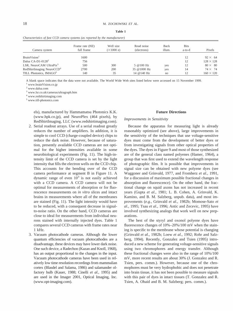
2. Serial readout arrays. Use of a serial readout greatlyreduces the number of amplifiers. In addition, it issimple to cool CCD (charge-coupled device) chips toreduce the dark noise. However, because of satura-tion, presently available CCD cameras are not opti-mal for the higher intensities available in someneurobiological experiments (Fig. 11). The high-in-tensity limit of the CCD camera is set by the lightintensity that fills the electron wells on the CCD chip.This accounts for the bending over of the CCDcamera performance at segment B in Figure 11. Adynamic range of even 103 is not easily achievedwith a CCD camera. A CCD camera will not beoptimal for measurements of absorption or for fluo-rescence measurements onin vitro slices and intactbrains in measurements where all of the membranesare stained (Fig. 11). The light intensity would haveto be reduced, with a consequent decrease in signal-to-noise ratio. On the other hand, CCD cameras areclose to ideal for measurements from individual neu-rons stained with internally injected dyes. Table 1compares several CCD cameras with frame rates near1 kHz.
3. Vacuum photocathode cameras. Although the lowerquantum efficiencies of vacuum photocathodes are adisadvantage, these devices may have lower dark noise.One such device, a Radechon (Kazan and Knoll, 1968),has an output proportional to the changes in the input.Vacuum photocathode cameras have been used in rel-atively low time resolution recordings from mammaliancortex (Blasdel and Salama, 1986) and salamander ol-factory bulb (Kauer, 1988; Cinelliet al., 1995) andare used in the Imager 2001, Optical Imaging, Inc.(www.opt-imaging.com).
Future Directions
Improvements in Sensitivity
Because the apparatus for measuring light is alreadyreasonably optimized (see above), large improvements inthe sensitivity of the techniques that use voltage-sensitivedyes must come from the development of better dyes orfrom investigating signals from other optical properties ofthe dyes. The dyes in Figure 9 and most of those synthesizedare of the general class named polyenes (Hamer, 1964), agroup that was first used to extend the wavelength responseof photographic film. It is possible that improvements insignal size can be obtained with new polyene dyes (seeWaggoner and Grinvald, 1977, and Fromherzet al., 1991,for a discussion of maximum possible fractional changes inabsorption and fluorescence). On the other hand, the frac-tional change on squid axons has not increased in recentyears (Guptaet al., 1981; L. B. Cohen, A. Grinvald, K.Kamino, and B. M. Salzberg, unpub. data), and most im-provements (e.g.,Grinvald et al., 1982b; Momose-Satoetal., 1995; Tsauet al.,1996; Antic and Zecevic, 1995) haveinvolved synthesizing analogs that work well on new prep-arations.
The best of the styryl and oxonol polyene dyes havefluorescence changes of 10%–20%/100 mV when the stain-ing is specific to the membrane whose potential is changing(Grinvald et al., 1982b; Loewet al., 1992; Rohr and Salz-berg, 1994). Recently, Gonzalez and Tsien (1995) intro-duced a new scheme for generating voltage-sensitive signalsusing two chromophores and energy transfer. Althoughthese fractional changes were also in the range of 10%/100mV, more recent results are about 30% (J. Gonzalez and R.Tsien, pers. comm.). However, because one of the chro-mophores must be very hydrophobic and does not penetrateinto brain tissue, it has not been possible to measure signalswith this pair of dyes in intact tissues (T. Gonzalez and R.Tsien, A. Obaid and B. M. Salzberg; pers. comm.).
Table 1
Characteristics of fast CCD camera systems (as reported by the manufacturer)
A blank space indicates that the data were not available. The World Wide Web sites listed below were accessed on 15 November 1999.1 www.brainVision.co.jp2 www.dalsa.com3 www.lsr.co.uk/cameras/ultragraph.htm4 www.redshirtimaging.com5 www.till-photonics.com
18 M. ZOCHOWSKI ET AL.
Bouevitchet al. (1993) and Ben-Orenet al. (1996) foundthat membrane potential changed the generation of nonlin-ear second harmonics from styryl dyes in cholesterol bilay-ers and in fly eyes. Large (50%) fractional changes weremeasured. It is hoped that improvements in the illuminationintensity will result in larger signal-to-noise ratios.
Ehrenberg and Berezin (1984) have used resonance Ra-man to study surface potential; these methods might also beapplicable for measuring transmembrane potential.
Improvements in Selectivity
An important new direction is the development of meth-ods for neuron-type–specific staining. Three quite differentapproaches have been tried. First, the use of retrogradestaining has been investigated in the embryonic chick andlamprey spinal cords (Tsauet al., 1996). An identified cellclass (motoneurons) was selectively stained. In lampreyexperiments, spike signals from individual neurons weresometimes measured (Hickieet al.,1996). Further efforts tooptimize this staining procedure are needed. Second is theuse of cell-type–specific staining developed for fluoresceinby Nirenberg and Cepko (1993). It might be possible to usesimilar techniques to selectively stain cells with voltage-sensitive or ion-sensitive dyes. Third, Siegel and Isacoff(1997) constructed a genetically encoded combination of apotassium channel and green fluorescent protein. Whenintroduced into a frog oocyte, this molecule had a (relativelyslow) voltage-dependent signal with a fractional fluores-cence change of 5%. Neuron-type–specific staining wouldmake it possible to determine the role of specific neurontypes in generating the input-output function of a brainregion.
Optical recordings already provide unique insights intobrain activity and organization. Improvements in sensitivityor selectivity would make these methods more powerful.
Acknowledgments
The authors are indebted to their collaborators VicencioDavila, Amiram Grinvald, Kohtaro Kamino, Les Loew, BillRoss, Brian Salzberg, Alan Waggoner, Jian-young Wu, andJoe Wuskell for numerous discussions about optical meth-ods. The experiments carried out in our laboratories weresupported by NIH grant NS08437 and NSF grant IBN-9812301.
Literature Cited
Adrian, E. D. 1942. Olfactory reactions in the brain of the hedgehog.J. Physiol.100: 459–473.
Albowitz, B., and U. Kuhnt. 1993. Spread of epileptiform potentials inthe neocortical slice: recordings with voltage-sensitive dyes.Brain Res.631: 329–333.
Antic, S., and D. Zecevic. 1995. Optical signals from neurons withinternally applied voltage-sensitive dyes.J. Neurosci.15: 1392–1405.
Antic, S., G. Major, and D. Zecevic. 1999. Fast optical recording ofmembrane potential changes from dendrites of pyramidal neurons.J. Neurophysiol.82: 1615–1621.
Ben-Oren, I., G. Peleg, A. Lewis, B. Minke, and L. Loew. 1996.Infrared nonlinear optical measurements of membrane potential inphotoreceptor cells.Biophys. J.71: 1616–1620.
Beuerman, R. W. 1975. Slow potentials of the turtle olfactory bulb inresponse to odor stimulation of the nose.Brain Res.97(1): 61–78.
Blasdel, G. G., and G. Salama. 1986.Voltage-sensitive dyes reveal amodular organization in monkey striate cortex.Nature321: 579–585.
Bouevitch, O., A. Lewis, I. Pinevsky, J. Wuskell, and L. Loew. 1993.Probing membrane potential with nonlinear optics.Biophys. J.65:672–679.
Boyle, M. B., and L. B. Cohen. 1980. Birefringence signals that monitormembrane potential in cell bodies of molluscan neurons.Fed. Proc.39:2130.
Braddick, H. J. J. 1960. Photoelectric photometry.Rep. Prog. Physics23: 154–175.
Bullen, A., S. S. Patel, and P. Saggau. 1997.High-speed, random-access fluorescence microscopy: I. High resolution optical recordingwith voltage-sensitive dyes and ion indicators.Biophys. J.73: 477–491.
Bullock, T. H., and M. C. McClune. 1989. Lateral coherence of theelectrocorticogram: a new measure of brain synchrony.Electroen-cephalogr. Clin. Neurophysiol.73: 479–498.
Cinelli, A. R., and B. M. Salzberg. 1992. Dendritic origin of late eventsin optical recordings from salamander olfactory bulb.J. Neurophysiol.68: 786–806.
Cinelli, A. R., S. R. Neff, and J. S. Kauer. 1995. Salamander olfactorybulb neuronal activity observed by video rate, voltage-sensitive dyeimaging. I. Characterization of the recording system.J. Neurophysiol.73: 2017–2032.
Cohen, L. B., and S. Lesher. 1986. Optical monitoring of membranepotential: methods of multisite optical measurement.Soc. Gen. Physiol.Ser.40: 71–99.
Cohen, L. B., and B. M. Salzberg. 1978. Optical measurement ofmembrane potential.Rev. Physiol. Biochem. Pharmacol.83: 35–88.
Dainty, J. C. 1984. Laser Speckle and Related Phenomena.Springer-Verlag, New York.
Davila, H. V., B. M. Salzberg, L. B. Cohen, and A. S. Waggoner. 1973.A large change in axon fluorescence that provides a promising methodfor measuring membrane potential.Nat. New. Biol.241: 159–160.
Davila, H. V., L. B. Cohen, B. M. Salzberg, and B. B. Shrivastav. 1974.Changes in ANS and TNS fluorescence in giant axons fromLoligo. J.Membr. Biol.15: 29–46.
Delaney, K. R., A. Gelperin, M. S. Fee, J. A. Flores, R. Gervais, D. W.Tank, and D. Kleinfeld. 1994. Waves and stimulus-modulated dy-namics in an oscillating olfactory network.Proc. Nat. Acad. Sci.91:669–673.
Denk, W., D. W. Piston, and W. Webb. 1995. Two-photon molecularexcitation in laser-scanning microscopy. Pp. 445–458 inHandbook ofBiological Confocal Microscopy,J. W. Pawley ed. Plenum Press, NewYork.
Ehrenberg, B., and Y. Berezin. 1984. Surface potential on purplemembranes and its sidedness studied by resonance Raman dye probe.Biophys. J.45: 663–670.
Eilers, J., G. Callewaert, C. Armstrong, and A. Konnerth. 1995. Cal-cium signaling in a narrow somatic submembrane shell during synapticactivity in cerebellar Purkinje neurons.Proc. Nat. Acad. Sci. US92:10272–10276.
Freeman, W. J. 1978. Spatial Properties of an EEG Event in the Olfac-tory Bulb and Cortex.Electroencephalogr. Clin. Neurophysiol.44:586–605.
Fromherz, P., K. H. Dambacher, H. Ephardt, A. Lambacher, C. O.
19IMAGING MEMBRANE POTENTIAL
Muller, R. Neigl, H. Schaden, O. Schenk, and T. Vetter. 1991.Fluorescent dyes as probes of voltage transients in neuron membranes:progress report.Ber. Bunsen-Ges. Phys. Chem.95: 1333–1345.
Gonzalez, J. E., and R. Y. Tsien. 1995. Voltage sensing by fluorescenceresonance energy transfer in single cells.Biophys. J.69: 1272–1280.
Grinvald, A., A. Manker, and M. Segal. 1982a. Visualization of thespread of electrical activity in rat hippocampal slices by voltage-sensitive optical probes.J. Physiol. (Lond)333: 269–291.
Grinvald, A., R. Hildesheim, I. C. Farber, and L. Anglister. 1982b.Improved fluorescent probes for the measurement of rapid changes inmembrane potential.Biophys. J.39: 301–308.
Grinvald, A., B. M. Salzberg, V. Lev-Ram, and R. Hildesheim. 1987.Optical recording of synaptic potentials from processes of single neu-rons using intracellular potentiometric dyes.Biophys. J.51: 643–651.
Grinvald, A., R. D. Frostig, E. Lieke, and R. Hildesheim. 1988. Op-tical imaging of neuronal activity.Physiol. Rev.68: 1285–1366.
Gross, E., R. S. Bedlack Jr., and L. M. Loew. 1994. Dual-wavelengthratiometric fluorescence measurements of the membrane dipole poten-tial. Biophys. J.67: 208–216.
Gupta, R. K., B. M. Salzberg, A. Grinvald, L. B. Cohen, K. Kamino, S.Lesher, M. B. Boyle, A. S. Waggoner, and C. H. Wang. 1981.Improvements in optical methods for measuring rapid changes inmembrane potential.J. Membr. Biol.58: 123–137.
Hamer, F. M. 1964. The Cyanine Dyes and Related Compounds.Wiley,New York.
Hickie, C., P. Wenner, M. O’Donovan, Y. Tsau, J. Fang, and L. B.Cohen. 1996. Optical monitoring of activity from individual andidentified populations of neurons retrogradely labeled with voltage-sensitive dyes.Soc. Neurosci. Abstr.22: 321.
Hirota, A., K. Sato, Y. Momose-Sato, T. Sakai, and K. Kamino. 1995.A new simultaneous 1020-site optical recording system for monitoringneural activity using voltage-sensitive dyes.J. Neurosci. Methods56:187–194.
Hughes, J. R., and J. A. Mazurowski. 1962. Studies on the supracal-losal mesial cortex of unanesthetized, conscious mammals. II Monkey.B. Responses from the olfactory bulb.Electroencephalogr. Clin. Neu-rophysiol.14: 635–645.
Iijima, T., M. Ichikawa, and G. Matsumoto. 1989. Optical monitoringof LTP and related phenomena.Soc. Neurosci. Abstr.15: 398.
Inoue, S. 1986. Video Microscopy.Plenum Press, New York. p 128.Kauer, J. S. 1988. Real-time imaging of evoked activity in local circuits
of the salamander olfactory bulb.Nature331: 166–168.Kazan, B., and M. Knoll. 1968. Electronic Image Storage.Academic
Press, New York.Kleinfeld, D., and K. R. Delaney. 1996. Distributed representation of
vibrissa movement in the upper layers of somatosensory cortex re-vealed with voltage-sensitive dyes.J. Comp. Neurol.375: 89–108.
Kogan, A., W. N. Ross, D. Zecevic, and N. Lasser-Ross. 1995.Opticalrecording from cerebellar Purkinje cells using intracellularly injectedvoltage-sensitive dyes.Brain Res.700: 235–239.
Kupfermann, I., H. Pinsker, V. Castellucci, and E. R. Kandel. 1971.Central and peripheral control of gill movements inAplysia. Science174: 1252–1256.
Lam, Y.-w., Lawrence B. Cohen, Matt Wachowiak, and Michal R.Zochowski. 2000. Odors elicit three different oscillations in the turtleolfactory bulb.J. Neurosci.In press.
Laurent, G., and M. Naraghi. 1994. Odorant-induced oscillations in themushroom bodies of the locust.J. Neurosci.14(5 Pt 2): 2993–3004.
Loew, L. M. 1993. Confocal microscopy of potentiometric fluorescentdyes.Methods Cell Biol.38: 195–209.
Loew, L. M., L. B. Cohen, B. M. Salzberg, A. L. Obaid, and F.Bezanilla. 1985. Charge-shift probes of membrane potential. Char-acterization of aminostyrylpyridinium dyes on the squid giant axon.Biophys. J.47: 71–77.
Loew, L. M., L. B. Cohen, J. Dix, E. N. Fluhler, V. Montana, G.Salama, and J. Y. Wu. 1992. A napthyl analog of the aminostyrylpyridinium class of potentiometric membrane dyes shows consistentsensitivity in a variety of tissue, cell, and model membrane prepara-tions.J. Memb. Biol.130: 1–10.
London, J. A., D. Zecevic, and L. B. Cohen. 1987. Simultaneousoptical recording of activity from many neurons during feeding inNavanax. J. Neurosci.7: 649–661.
Magee, J. C., and D. Johnston. 1995.Synaptic activation of voltage-gated channels in the dendrites of hippocampal pyramidal neurons.Science268: 301–304.
Magee, J. C., G. Christofi, H. Miyakawa, B. Christie, N. Lasser-Ross,and D. Johnston. 1995. Subthreshold synaptic activation of voltage-gated calcium channels mediate a localized calcium influx into den-drites of hippocampal pyramidal neurons.J. Neurophysiol.74: 335–342.
Mainen, Z. F., N. T. Carnevalle, A. M. Zador, B. J. Claiborne, andT. H. Brown. 1996. Electronic architecture of hippocampal CA1pyramidal neurons based on three-dimensional reconstructions.J. Neu-rophysiol.76: 1904–1923.
Malmstadt, H. V., C. G. Enke, S. R. Crouch, and G. Harlick. 1974.Electronic Measurements for Scientists.Benjamin, Menlo Park, CA.
Markram, H., and B. Sakmann. 1994. Calcium transients in dendritesof neocortical neurons evoked by single subthreshold excitatorypostsynaptic potentialsvia low-voltage-activated calcium channels.Proc. Nat. Acad. Sci.91: 5207–5211.
Momose-Sato, Y., K. Sato, T. Sakai, A. Hirota, K. Matsutani, and K.Kamino. 1995. Evaluation of optimal voltage-sensitive dyes for op-tical measurement of embryonic neural activity.J. Membr. Biol.144:167–176.
Nakashima, M., S. Yamada, S. Shiono, M. Maeda, and F. Satoh. 1992.448-detector optical recording system: development and application toAplysiagill-withdrawal reflex.IEEE Trans. Biomed. Eng.39: 26–36.
Nirenberg, S., and C. Cepko. 1993. Targeted ablation of diverse cellclasses in the nervous systemin vivo. J. Neurosci.13: 3238–3251.
Obaid, A. L., T. Koyano, J. Lindstrom, T. Sakai, and B. M. Salzberg.1999. Spatiotemporal patterns of activity in an intact mammaliannetwork with single-cell resolution: optical studies of nicotinic activityin an enteric plexus.J. Neurosci.19: 3073–3093.
Orbach, H. S., and L. B. Cohen. 1983. Optical monitoring of activityfrom many areas of thein vitro andin vivo salamander olfactory bulb:a new method for studying functional organization in the vertebratecentral nervous system.J. Neurosci.3: 2251–2262.
Orbach, H. S., L. B. Cohen, and A. Grinvald. 1985. Optical mappingof electrical activity in rat somatosensory and visual cortex.J. Neuro-sci. 5: 1886–1895.
Petran, M., and M. Hadravsky. 1966. Czechoslovakian patent 7720.Prechtl, J. C., L. B. Cohen, B. Peseran, P. P. Mitra, and D. Kleinfeld.
1997. Visual stimuli induce waves of electrical activity in turtlecortex.Proc. Nat. Acad. Sci. USA94: 7621–7626.
Ratzlaff, E. H., and A. Grinvald. 1991. A tandem-lens epifluorescencemicroscope: hundred-fold brightness advantage for wide-field imaging.J. Neurosci. Meth.36: 127–137.
Rohr, S., and B. M. Salzberg. 1994. Multiple site optical recording oftransmembrane voltage in patterned growth heart cell cultures: assess-ing electrical behavior, with microsecond resolution, on a cellular andsubcellular scale.Biophys. J.67: 1301–1315.
Ross, W. N., and L. F. Reichardt. 1979. Species-specific effects on theoptical signals of voltage-sensitive dyes.J. Membr. Biol.48: 343–356.
Ross, W. N., B. M. Salzberg, L. B. Cohen, A. Grinvald, H. V. Davila,A. S. Waggoner, and C. H. Wang. 1977. Changes in absorption,fluorescence, dichroism, and birefringence in stained giant axons: op-tical measurement of membrane potential.J. Membr. Biol.33: 141–183.
20 M. ZOCHOWSKI ET AL.
Sakai, T., A. Hirota, H. Komuro, S. Fujii, and K. Kamino. 1985.Optical recording of membrane potential responses from early embry-onic chick ganglia using voltage-sensitive dyes.Brain Res.349: 39–51.
Salama, G. 1988. Voltage-sensitive dyes and imaging techniques revealnew patterns of electrical activity in heart and cortex.Proc. SPIE (Int.Soc. Optical Eng.)94: 75–86.
Salzberg, B. M. 1983. Optical recording of electrical activity in neuronsusing molecular probes. Pp. 139–187 inCurrent Methods in CellularNeurobiology.J. L. Barker and J. F. McKelvy, eds. Wiley, New York.
Salzberg, B. M., H. V. Davila, and L. B. Cohen. 1973. Optical record-ing of impulses in individual neurones of an invertebrate central ner-vous system.Nature246: 508–509.
Salzberg, B. M., A. Grinvald, L. B. Cohen, H. V. Davila, and W. N.Ross. 1977. Optical recording of neuronal activity in an invertebratecentral nervous system: simultaneous monitoring of several neurons.J. Neurophysiol.40: 1281–1291.
Schiller, J., F. Helmchen, and B. Sakmann. 1995. Spatial profile ofdendritic calcium transients evoked by action potentials in rat neocor-tical pyramidal neurons.J. Physiol.487: 583–600.
Shaw, R. 1979. Photographic detectors.Appl. Optics Optical Eng.7:121–154.
Siegel, M. S., and E. Y. Isacoff. 1997. A genetically encoded opticalprobe of membrane voltage.Neuron19: 735–41.
Spruston, N., Y. Schiller, G. Stuart, and B. Sakmann. 1995. Activity-dependent action potential invasion and calcium influx into hippocam-pal CA1 dendrites.Science268: 297–300.
Stuart, G. J., and B. Sakmann. 1994. Active propagation of somaticaction potentials into neocortical pyramidal cell dendrites.Nature367:69–72.
Tank, D., and Z. Ahmed. 1985. Multiple-site monitoring of activity incultured neurons.Biophys. J.47: 476A.
Tsau, Y., J. Y. Wu, H. P. Hopp, L. B. Cohen, D. Schiminovich, and
C. X. Falk. 1994. Distributed aspects of the response to siphon touchin Aplysia: spread of stimulus information and cross-correlation anal-ysis.J. Neurosci.14: 4167–4184.
Tsau, Y., P. Wenner, M. J. O’Donovan, L. B. Cohen, L. M. Loew, andJ. P. Wuskell. 1996. Dye screening and signal-to-noise ratio forretrogradely transported voltage-sensitive dyes.J. Neurosci. Meth.70:121–129.
Waggoner, A. S. 1979. Dye indicators of membrane potential.Annu.Rev. Biophys. Bioeng.8: 47–68.
Waggoner, A. S., and A. Grinvald. 1977. Mechanisms of rapid opticalchanges of potential sensitive dyes.Annu. NY Acad. Sci.303:217–241.
Wu, J. Y., and L. B. Cohen. 1993. Fast multisite optical measurementsof membrane potential. Pp. 389–404 inFluorescent and LuminescentProbes for Biological Activity.W. T. Mason, ed. Academic Press,London.
Wu, J. Y., L. B. Cohen, and C. X. Falk. 1994a. Neuronal activityduring different behaviors suggests a distributed neuronal organizationin the Aplysiaabdominal ganglion.Science263: 820–823.
Wu, J. Y., Y. Tsau, H. P. Hopp, L. B. Cohen, A. C. Tang, and C. X.Falk. 1994b. Consistency in nervous systems: trial-to-trial and ani-mal-to-animal variations in the response to repeated application of asensory stimulus inAplysia. J. Neurosci.14: 1366–1384.
Wu, J. Y., Y. W. Lam, C. X. Falk, L. B. Cohen, J. Fang, L. Loew, J. C.Prechtl, D. Kleinfeld, and Y. Tsau. 1998. Voltage-sensitive dyes formonitoring multi-neuronal activity in the intact CNS.Histochem. J.30:169–187.
Yuste, R., and W. Denk. 1995. Dendritic spines as basic functional unitsof neuronal integration.Nature375: 682–684.
Zecevic, D. 1996. Multiple spike-initiation zones in single neurons re-vealed by voltage-sensitive dyes.Nature381: 322–325.
Zecevic, D., J. Y. Wu, L. B. Cohen, J. A. London, H. P. Hopp, and C. X.Falk. 1989. Hundreds of neurons in theAplysiaabdominal ganglionare active during the gill-withdrawal reflex.J. Neurosci.9: 3681–3689.