44
Concepts of Special Relativity Michel Betz January 22, 2020

Concepts of SpecialRelativity
Michel Betz
January 22, 2020
Preamble
This text presents the main basic kinematics concepts of Special Relativity, namely, timedilation, length contraction and the combination law for collinear velocities. The popular“twin paradox” is also discussed.
The approach employed was developed by the British cosmologist Hermann Bondi andis known in the literature as “k calculus”, for it makes use, as basic quantity to specify therelationship between two observers in relative motion, of an adimensional factor for whichBondi adopted the notation k. This factor is nothing more than the factor characteristic of theDoppler effect for light, that is, the ratio between the period of emission of light signals, byone of the observers, and the corresponding period of reception by the other. Bondi showedthat the use of this factor in the analysis of specific situations involving the exchange of lightpulses between two, or more, observers affords a particularly simple deduction of the, apriori counterintuitive, effects implied by the postulates of Special Relativity.
In the present work, each relevant situation is presented and analysed successively in ageneric (algebraic) mathematical notation. In an appendix, concrete cases are consideredfor which numerical results are obtained. Diagrams for the visualization of the involvedmotions in space-time, known as Minkowski diagrams, are used to illustrate the genericsituations and the specific examples as well.
This text accompanies a set of computerized animations which allow, for each situation,the visualization on the screen of the motions of the various observers, light pulses and otherbodies, together with the simultaneous dynamical construction of the Minkowski diagram andof a table registering the occurrence times of the relevant events.
i
Chapter 1
A few basic concepts
1.1 Introduction
This chapter defines a few basic concepts, which are indispensable for the development ofrelativistic kinematics and will be used repeatedly in all the arguments. It also introduces agraphical representation of the motions, which will facilitate the visualization of the situationsconsidered for establishing the main consequences of the principles of Special Relativity.
1.2 Event
An event is something that happens in some specific place at some specific time. Your birth,or the emission of a flash by a photographic camera, are examples of events. Evidently, oneis dealing, in most cases, with an idealization, valid if the phenomenon in question had abrief duration and happened in a region of small spatial extension.
1.3 Observer
An observer is somebody who observes and describes events. Distinct observers maydescribe the same event in different manners. It should be emphasized that one is notreferring here to any subjective difference, but rather to differences that can be rationallyexplained in terms of the states of motion of the observers.
1.4 Referential
In order to describe an event with precision, an observer utilizes a reference system, orreferential. A referential consists of a position coordinate system, employed to specifywhere the event takes place, and of a time scale, used to stipulate the instant at which theevent occurs. Positions can be determined with a metric tape (to measure distances) and atheodolite (to measure angles). Times can be measured with a clock. Thus, concretely, onemay associate a referential to an observer equipped with a metric tape, a theodolite and a
1
CHAPTER 1. A FEW BASIC CONCEPTS 2
clock. In general, distinct observers will attribute to the same event different positions anddifferent times.
1.5 Space-time
In the study of Relativity, it is frequently convenient to join the (three-dimensional) positionspace together with the (one-dimensional) time scale to form a single (four-dimensional)space called space-time. To every event, is associated a point in space-time. The historyof any localized entity may be considered as a continuous succession of events. Therefore,such history is represented in space-time by a continuous line, known as the entity’s worldline.
1.6 Minkowski diagram
The space-time of events and the world lines of physical entities may be visualized with thehelp of a Minkowski diagram. It is not possible to draw in four dimensions and thereforeone must “forget” at least one of the position directions in order to draw a Minkowski diagram.Given that a sheet of paper, or the screen of a computer, are two-dimensional surfaces, moreclarity in the drawing is achieved if one can “forget” two spatial directions. The condition forthis to be possible is that all events considered happen on the same straight line of positionspace. This will be the case for all situations considered in this text.
In a Minkowski diagram, an event is represented by a point. Defining in the diagram asystem of orthogonal axes, the event’s occurrence time is measured along one of the axesand the event’s position is measured along the other axis. In this text, we stipulate thatthe occurrence time is given in abscissa (horizontal axis on the computer screen) and theposition is given in ordinate (vertical axis on the screen). We should emphasize that thisconvention is arbitrary and many Relativity textbooks, as well as research articles,make use of the opposite convention. The convention adopted here offers the advantageof corresponding to the usual graphic representation of a function, in which the values of thevariable are indicated in abscissa and the corresponding values of the function in ordinate.In a Minkowski diagram, the world line of an entity shows the variation of the entity’s positionas a function of time.
As will be seen in the presentation of the postulates of Special Relativity, the velocity oflight in vacuum plays an important role in the theory, namely that of a fundamental universalconstant. For this reason, it is convenient to use a unit of distance related to the unit of timein such a way that the velocity of light be equal to one. One example of such a distanceunit, ordinarily used in Astronomy, is the light-year, which is the distance traveled by lightin a year. Obviously then, the velocity of light is one light-year per year. With such units,during a unit time interval, a light pulse moves over a unit distance. Consequently, theworld lines of light pulses are straight lines inclined at 45 degrees in a Minkowski diagram.According to Special Relativity, no signal or body can move with velocity above the speed oflight. Therefore, in a Minkowski diagram, no world line can have an inclination superior to 45degrees with respect to the horizontal axis. As a consequence, the width of such diagrams
CHAPTER 1. A FEW BASIC CONCEPTS 3
will usually be greater than their height. One should stress that this characteristic resultsfrom the choice of the horizontal direction for the time axis and constitutes an additionalmotivation for adopting that convention: the present text accompanies an animation programand a computer screen is, at least in its usual orientation, wider than it is high.
Since the space and time coordinates depend on the referential used, one always needsto specify which observer is measuring the values indicated in abscissa and in ordinate in aMinkowski diagram. .
..........
..........
..........
..........
..........
..........
..........
..........
..........
..........
..........
..........
..........
..........
..........
..........
..........
..........
..........
..........
..........
..........
..........
..........
..........
..........
..........
..........
..........
..........
..........
..........
..........
..........
..........
..........
..........
..........
..........
..........
..........
..........
..........
..........
..........
..........
..........
..........
..........
.........................
.................x
............................................................................................................................................................................................................................................................................................................................................................................................................................................................................................................................................................................................................................................................................................................................................................................................ .................A
...........................................................................................................................................................................................................................................................................................................................................................................................................................................................................................................................................................................................................................................................................................................................................................................D
t..............................................................................
..............................................................................
..............................................................................
..............................................................................
..............................................................................
..............................................................................
..............................................................................
..............................................................................
..............................................................................
.......................................................................
B’
.........................................................................................................................................................................................................................................................................................................................................................................................................................................................................................................................................................................................................................................................................................................................C”
............................
............................
............................
............................
............................
............................
............................
............................
........................................................................................................................................................................................................................................................................................................................ ................................
................................
................................
................................................................
O
P
Q
I
R
F..........................................................................................................................................................................................................................................................................................
tR
xR
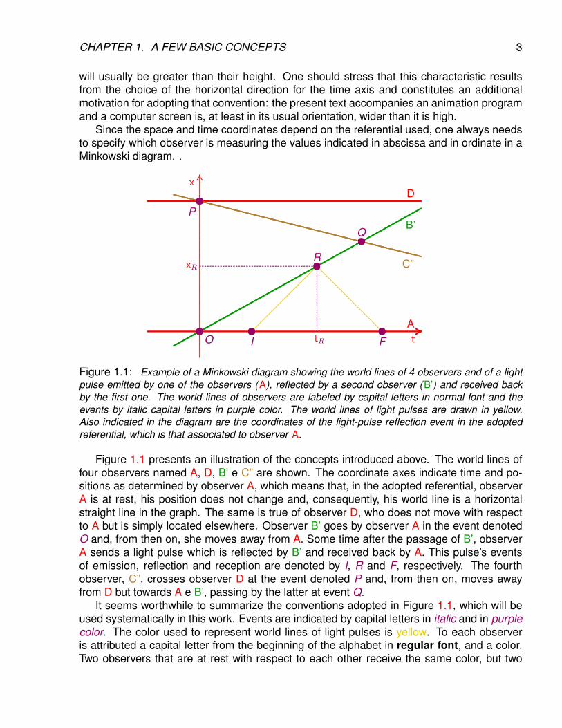
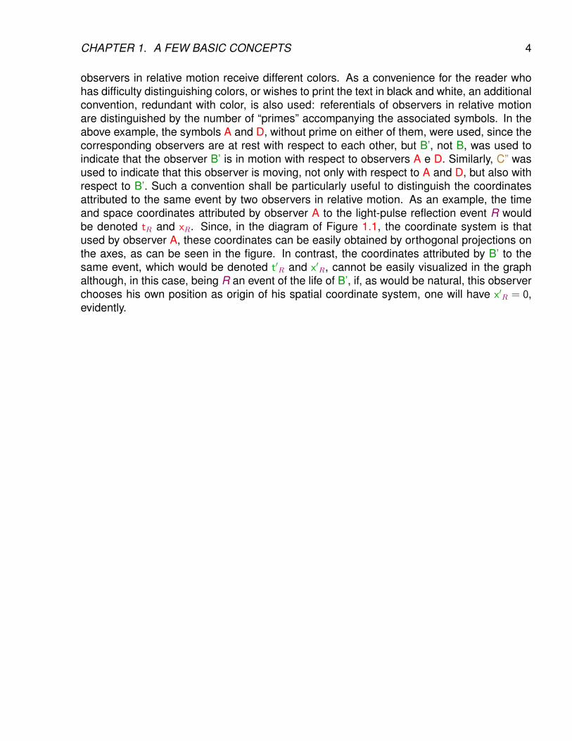
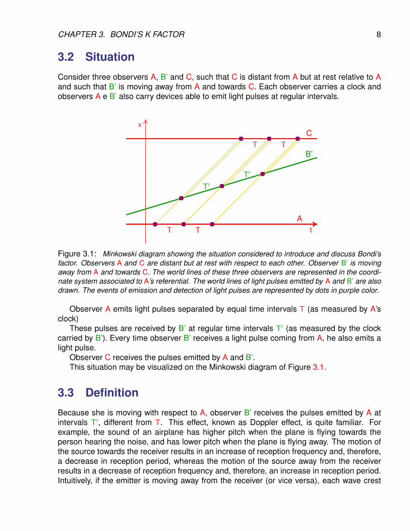
Figure 1.1: Example of a Minkowski diagram showing the world lines of 4 observers and of a lightpulse emitted by one of the observers (A), reflected by a second observer (B’) and received backby the first one. The world lines of observers are labeled by capital letters in normal font and theevents by italic capital letters in purple color. The world lines of light pulses are drawn in yellow.Also indicated in the diagram are the coordinates of the light-pulse reflection event in the adoptedreferential, which is that associated to observer A.
Figure 1.1 presents an illustration of the concepts introduced above. The world lines offour observers named A, D, B’ e C” are shown. The coordinate axes indicate time and po-sitions as determined by observer A, which means that, in the adopted referential, observerA is at rest, his position does not change and, consequently, his world line is a horizontalstraight line in the graph. The same is true of observer D, who does not move with respectto A but is simply located elsewhere. Observer B’ goes by observer A in the event denotedO and, from then on, she moves away from A. Some time after the passage of B’, observerA sends a light pulse which is reflected by B’ and received back by A. This pulse’s eventsof emission, reflection and reception are denoted by I, R and F, respectively. The fourthobserver, C”, crosses observer D at the event denoted P and, from then on, moves awayfrom D but towards A e B’, passing by the latter at event Q.
It seems worthwhile to summarize the conventions adopted in Figure 1.1, which will beused systematically in this work. Events are indicated by capital letters in italic and in purplecolor. The color used to represent world lines of light pulses is yellow. To each observeris attributed a capital letter from the beginning of the alphabet in regular font, and a color.Two observers that are at rest with respect to each other receive the same color, but two
CHAPTER 1. A FEW BASIC CONCEPTS 4
observers in relative motion receive different colors. As a convenience for the reader whohas difficulty distinguishing colors, or wishes to print the text in black and white, an additionalconvention, redundant with color, is also used: referentials of observers in relative motionare distinguished by the number of “primes” accompanying the associated symbols. In theabove example, the symbols A and D, without prime on either of them, were used, since thecorresponding observers are at rest with respect to each other, but B’, not B, was used toindicate that the observer B’ is in motion with respect to observers A e D. Similarly, C” wasused to indicate that this observer is moving, not only with respect to A and D, but also withrespect to B’. Such a convention shall be particularly useful to distinguish the coordinatesattributed to the same event by two observers in relative motion. As an example, the timeand space coordinates attributed by observer A to the light-pulse reflection event R wouldbe denoted tR and xR. Since, in the diagram of Figure 1.1, the coordinate system is thatused by observer A, these coordinates can be easily obtained by orthogonal projections onthe axes, as can be seen in the figure. In contrast, the coordinates attributed by B’ to thesame event, which would be denoted t′R and x′R, cannot be easily visualized in the graphalthough, in this case, being R an event of the life of B’, if, as would be natural, this observerchooses his own position as origin of his spatial coordinate system, one will have x′R = 0,evidently.
Chapter 2
Introduction and Principles
2.1 Introduction
In this chapter, a few important aspects of classical physics are briefly reviewed, more specif-ically those related to the motion of bodies and the propagation of waves. Then the twofundamental postulates of Relativity are enunciated, with emphasis upon their relations toand differences from the classical concepts previously recalled.
2.2 Classical Mechanics
Classical or Newtonian mechanics sets forth the general laws of motion of bodies when theirvelocities are much smaller than the velocity of light.
Newton’s first law states that there exists a class of referentials in which all bodies, freefrom any influence of other bodies, are in uniform rectilinear motion or at rest. Such referen-tials are called inertial referentials. A referential in uniform rectilinear motion with respectto an inertial referential is also inertial.
In Newtonian mechanics, time is absolute, that is, it is the same in all referentials. Thelaws of classical mechanics are formulated in inertial referentials and are the same inall inertial referentials.
Newton’s second law introduces the concept of force to represent the influence of otherbodies on the motion of a given body. It states that force produces acceleration.
Newtonian mechanics embodies Galileo’s principle according to which it is not possible,through the observation of physical phenomena happening within a closed laboratory, todetermine whether the latter is in uniform rectilinear motion or at rest.
In the conceptual framework of Newtonian mechanics, there is no limit to the value thatthe propagation velocity of a particle or signal can assume. As a consequence, that the-ory admits the notion of instantaneous influence at a distance. As emphasized below, inEinstein’s Relativity, a more general and precise theory, there is a limit to the propagationvelocity of any signal and instantaneous action at a distance can only be assumed as anapproximation valid in certain circumstances.
5
CHAPTER 2. INTRODUCTION AND PRINCIPLES 6
2.3 Waves in a material medium
The laws of propagation of material waves are normally formulated in a referential inwhich the propagation medium is at rest. For a sound wave, for example, the propagationvelocity with respect to the medium is a characteristic property of that medium.
If the material medium of propagation is moving in the referential of the observer, theobserved wave propagation velocity results from the combination of the medium velocity withthe wave propagation velocity with respect to the medium. Therefore, the velocity attributedto the wave by the observer depends on the velocity of the medium.
The observed frequency is affected by the velocity, with respect to the propagationmedium, of the emitter as well as of the receiver.
2.4 Light
Light is a wave phenomenon, more precisely, an electromagnetic wave which, contrary tosound, can propagate in regions of space in which there is no matter. All attempts to identifya propagation medium (the hypothetical ether) have failed and it may be stated that lightpropagates in vacuum.
2.5 Postulates of Special Relativity
Special Relativity is essentially contained in two postulates that can be enunciated verysimply:
• All laws of Physics are valid in all inertial referentials.
• The velocity of light in vacuum is a universal constant, independent of frequencyand of the source’s motion.
However, the simultaneous acceptation of these postulates immediately leads to a dramaticconclusion: the velocity of light assumes the same value in all inertial referentials.This conclusion conflicts with our intuitive notions on the combination of velocities but itsvalidity was confirmed by a famous experiment realized by Michelson and Morley, whoshowed that the velocity of light in a terrestrial laboratory is not affected by the Earth’s orbitalmotion around the Sun. Given this, the development of Special Relativity will clearly requirea profound revision of our concepts of space and time.
Simply on the basis of the two postulates stated above, the possibility of some particleor signal propagating faster than light could not be discarded. Such entities, known in theliterature as tachyons, have been a frequent subject of theoretical study and experimentalsearch. It may be claimed, however, that there is no convincing evidence for their existence,which would be quite problematic from a conceptual point of view for it would imply thepossibility of the future influencing the past. This question will not be further addressedin this work, which shall adopt the additional hypothesis that the speed of light is a limitthat is reached by electromagnetic waves and possibly other fields or particles, but is neverovercome.
Chapter 3
Bondi’s k factor
3.1 Introduction
In the development of Special Relativity, an essential task is to establish the relationshipsbetween measurements of time, distance and other related quantities, performed by twoinertial observers. For this purpose, it is first necessary to characterize the motion of one ofthe observers with respect to the other. The procedure most usually used is to stipulate therelative velocity of the observers. However, as already anticipated in the previous chapter,the concept of velocity itself will need to be reassessed in Special Relativity and to invoke itfrom the start is questionable from a conceptual point of view and, in fact, fairly inconvenientin practice.
Seeking an alternative approach, the cosmologist Hermann Bondi proposed as a startingpoint to consider light pulses emitted by the first observer and received by the second. Theratio between the reception and emission time intervals of such pulses, which Bondi called kfator, can be conveniently adopted as the basic quantity to specify the relationship betweenthe observers. If these are at rest with respect to each other, the k factor will obviouslybe equal to one, but if they are moving towards or away from each other, the value of kwill be different from one. One only needs to imagine a sequence of pulses emitted (andtherefore also received) at regular time intervals to be able to interpret the k factor as theration between the repetition periods of reception and emission. The fact that this ratio differsfrom unity when the receiver is moving with respect to the emitter is nothing else than theDoppler effect, well known from classical wave theory.
Bondi’s k factor will be used systematically in all developments of this work as basicquantity to characterize the relation between observers in uniform rectilinear motion withrespect to each other. In the present chapter, a few elementary properties of the k factor willbe discussed on the basis of the Special Relativity postulates
7
CHAPTER 3. BONDI’S K FACTOR 8
3.2 Situation
Consider three observers A, B’ and C, such that C is distant from A but at rest relative to Aand such that B’ is moving away from A and towards C. Each observer carries a clock andobservers A e B’ also carry devices able to emit light pulses at regular intervals.
..........
..........
..........
..........
..........
..........
..........
..........
..........
..........
..........
..........
..........
..........
..........
..........
..........
..........
..........
..........
..........
..........
..........
..........
..........
..........
..........
..........
..........
..........
..........
..........
..........
..........
..........
..........
..........
..........
..........
..........
..........
..........
..........
..........
..........
..........
....................
.................x
......................................................................................................................................................................................................................................................................................................................................................................................................................................................................................................................................................................................................................................................................................................................................................... .................A
........................................................................................................................................................................................................................................................................................................................................................................................................................................................................................................................................................................................................................................................................................................................................C
tT T
T T
..................................................................................................................................
..................................................................................................................................
..................................................................................................................................
..................................................................................................................................
..................................................................................................................................
.............................................................................................B’
T′T′
............................
............................
............................
............................
............................
............................
............................
............................
............................
............................
............................
............................
............................
............................
............................
............................
.....
............................
............................
............................
............................
............................
............................
............................
............................
............................
............................
............................
............................
............................
............................
............................
............................
.....
............................
............................
............................
............................
............................
............................
............................
............................
............................
............................
............................
........
............................
............................
............................
............................
............................
............................
............................
............................
......................
............................
............................
............................
............................
............................
............................
.............
....................... ....................... .......................
....................... ....................... .......................
..............................................
.......................
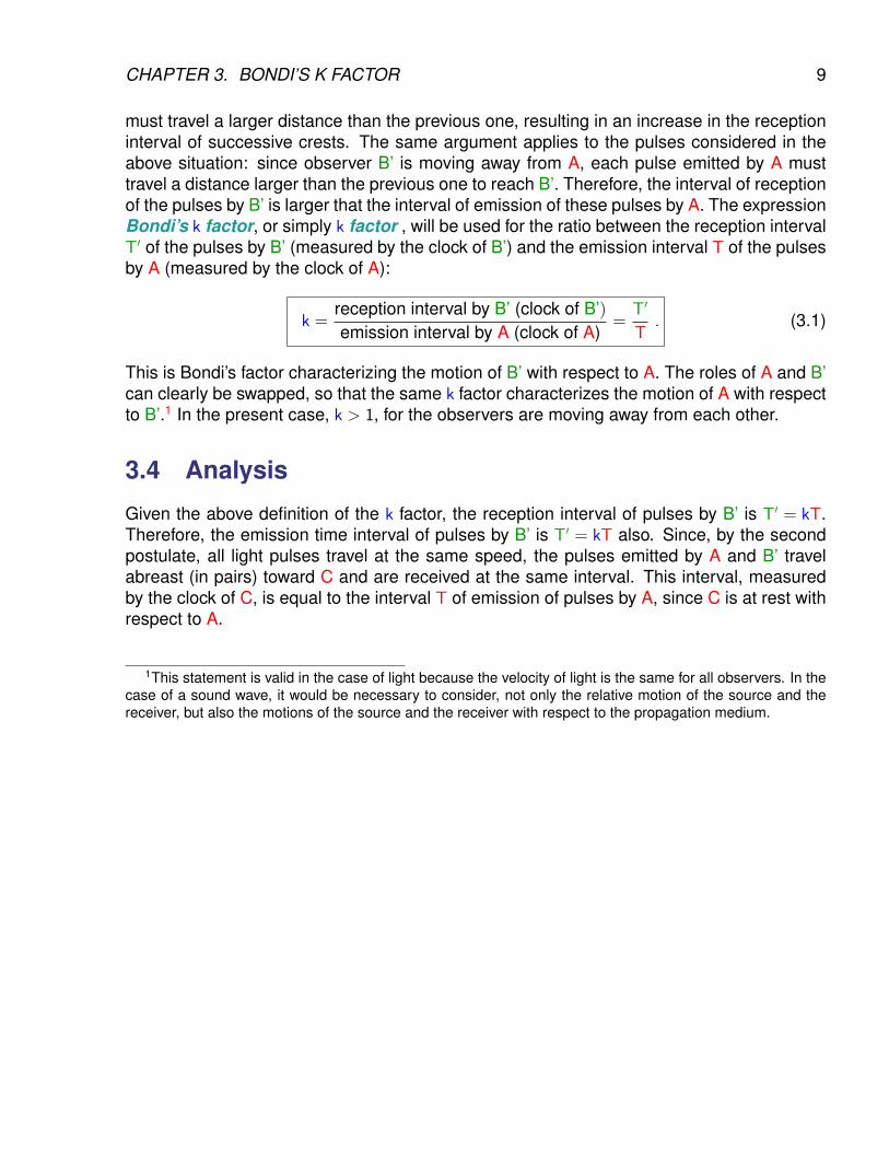
Figure 3.1: Minkowski diagram showing the situation considered to introduce and discuss Bondi’sfactor. Observers A and C are distant but at rest with respect to each other. Observer B’ is movingaway from A and towards C. The world lines of these three observers are represented in the coordi-nate system associated to A’s referential. The world lines of light pulses emitted by A and B’ are alsodrawn. The events of emission and detection of light pulses are represented by dots in purple color.
Observer A emits light pulses separated by equal time intervals T (as measured by A’sclock)
These pulses are received by B’ at regular time intervals T′ (as measured by the clockcarried by B’). Every time observer B’ receives a light pulse coming from A, he also emits alight pulse.
Observer C receives the pulses emitted by A and B’.This situation may be visualized on the Minkowski diagram of Figure 3.1.
3.3 Definition
Because she is moving with respect to A, observer B’ receives the pulses emitted by A atintervals T′, different from T. This effect, known as Doppler effect, is quite familiar. Forexample, the sound of an airplane has higher pitch when the plane is flying towards theperson hearing the noise, and has lower pitch when the plane is flying away. The motion ofthe source towards the receiver results in an increase of reception frequency and, therefore,a decrease in reception period, whereas the motion of the source away from the receiverresults in a decrease of reception frequency and, therefore, an increase in reception period.Intuitively, if the emitter is moving away from the receiver (or vice versa), each wave crest
CHAPTER 3. BONDI’S K FACTOR 9
must travel a larger distance than the previous one, resulting in an increase in the receptioninterval of successive crests. The same argument applies to the pulses considered in theabove situation: since observer B’ is moving away from A, each pulse emitted by A musttravel a distance larger than the previous one to reach B’. Therefore, the interval of receptionof the pulses by B’ is larger that the interval of emission of these pulses by A. The expressionBondi’s k factor, or simply k factor , will be used for the ratio between the reception intervalT′ of the pulses by B’ (measured by the clock of B’) and the emission interval T of the pulsesby A (measured by the clock of A):
k =reception interval by B’ (clock of B’)emission interval by A (clock of A)
=T′
T. (3.1)
This is Bondi’s factor characterizing the motion of B’ with respect to A. The roles of A and B’can clearly be swapped, so that the same k factor characterizes the motion of A with respectto B’.1 In the present case, k > 1, for the observers are moving away from each other.
3.4 Analysis
Given the above definition of the k factor, the reception interval of pulses by B’ is T′ = kT.Therefore, the emission time interval of pulses by B’ is T′ = kT also. Since, by the secondpostulate, all light pulses travel at the same speed, the pulses emitted by A and B’ travelabreast (in pairs) toward C and are received at the same interval. This interval, measuredby the clock of C, is equal to the interval T of emission of pulses by A, since C is at rest withrespect to A.
1This statement is valid in the case of light because the velocity of light is the same for all observers. In thecase of a sound wave, it would be necessary to consider, not only the relative motion of the source and thereceiver, but also the motions of the source and the receiver with respect to the propagation medium.
CHAPTER 3. BONDI’S K FACTOR 10
3.5 Summary
A B’ Cemission interval T −→ reception interval kT
emission interval kT −→ reception interval T
3.6 Conclusion
The ratio between the reception interval of pulses by C (measured by the clock of C) and theemission interval by B’ (measured by the clock of B’) is
k =reception interval by C (clock of C)
emission interval by B’ (clock of B’)=
T
T′=
T
kT=
1
k. (3.2)
The k factor thus defined characterizes the motion of observer C with respect to observerB’ or, equivalently, the motion of observer B’ with respect to observer C. In this case, k < 1,since the two observers in question are moving toward each other.
3.7 Synopsis
Relative motion of emitter and receiver reception intervalemission interval
away from each other ktoward each other 1/k
3.8 Comments
The notion of a k factor different from unity is not peculiar to Special Relativity, it is merelythe Doppler effect. But the relationship displayed in the above synopsis is characteristic ofSpecial Relativity, for it embodies the independence of the velocity of a light signal from thevelocities of the source and of the receptor.
The k factor is quite convenient to characterize the relative motion of two inertial ob-servers but, once this concept is introduced, the relative velocity v, more customarily utilizedas starting point in presentations of Special Relativity, can naturally be deduced as a functionof k. This will be done in the next chapter.
Chapter 4
Relation between the k factor andthe relative velocity v
4.1 Introduction
Most presentations of Relativity utilize the relative velocity to specify the kinematic relationbetween two observers. Although less convenient than Bondi’s factor, this variable is impor-tant and this chapter is devoted to establishing the relationship between the two quantities.
4.2 Situation
An observer B’ is in uniform rectilinear motion with respect to another observer A. ObserverA carries a device capable of emitting and detecting light pulses, whereas observer B’ carriesa mirror capable of reflecting the pulses sent by A.
When B’ passes by A, both reset their clocks to zero; denoting this event by O, one hastherefore tO = t′O = 0.
Also when B’ passes by A, the latter sends a first light pulse to B’. Since A and B’ areat the same place at that instant, this pulse is reflected essentially instantaneously by themirror and the reflected pulse is received by A at the same instant. That is, one may considerthat the events of emission, reflection and reception of this first pulse all coincide with eventO.
Observer B’ then begins to move away from A. This motion of one observer with respectto the other may be characterized by the Bondi factor k.
Some time later, observer A sends a second light pulse to B’; this pulse is reflected bythe mirror and received back by A. One may denote by I, R and F, respectively, the eventsof emission (by A), reflection (by B’) and reception (by A) of this pulse.
The situation described above is represented in the Minkowski diagram of Figure 4.1.Naturally, the first pulse, the existence of which has arbitrarily short duration, is not visible.Besides the elements introduced above, the graph shows the necessary construction inorder to extract the coordinates (tR, xR) of the event R of reflection of the second pulse;these coordinates play a central role in the analysis of the next section.
11
CHAPTER 4. RELATION BETWEEN THE K FACTOR AND THE RELATIVE VELOCITY V12
..........
..........
..........
..........
..........
..........
..........
..........
..........
..........
..........
..........
..........
..........
..........
..........
..........
..........
..........
..........
..........
..........
..........
..........
..........
..........
..........
..........
..........
..........
..........
..........
..........
..........
..........
..........
..........
..........
..........
..........
..........
..........
........................
.................x
......................................................................................................................................................................................................................................................................................................................................................................................................................................................................................................................................................................................................................................................................................................................................................... .................AttR
xR
..............................................................................
..............................................................................
..............................................................................
..............................................................................
..............................................................................
..............................................................................
..............................................................................
..............................................................................
..............................................................................
.......................................
B’
............................
............................
............................
............................
............................
............................
............................
............................
............................................................................................................................................................................................................................................................................................................... .......................
.......................
.......................O I
R
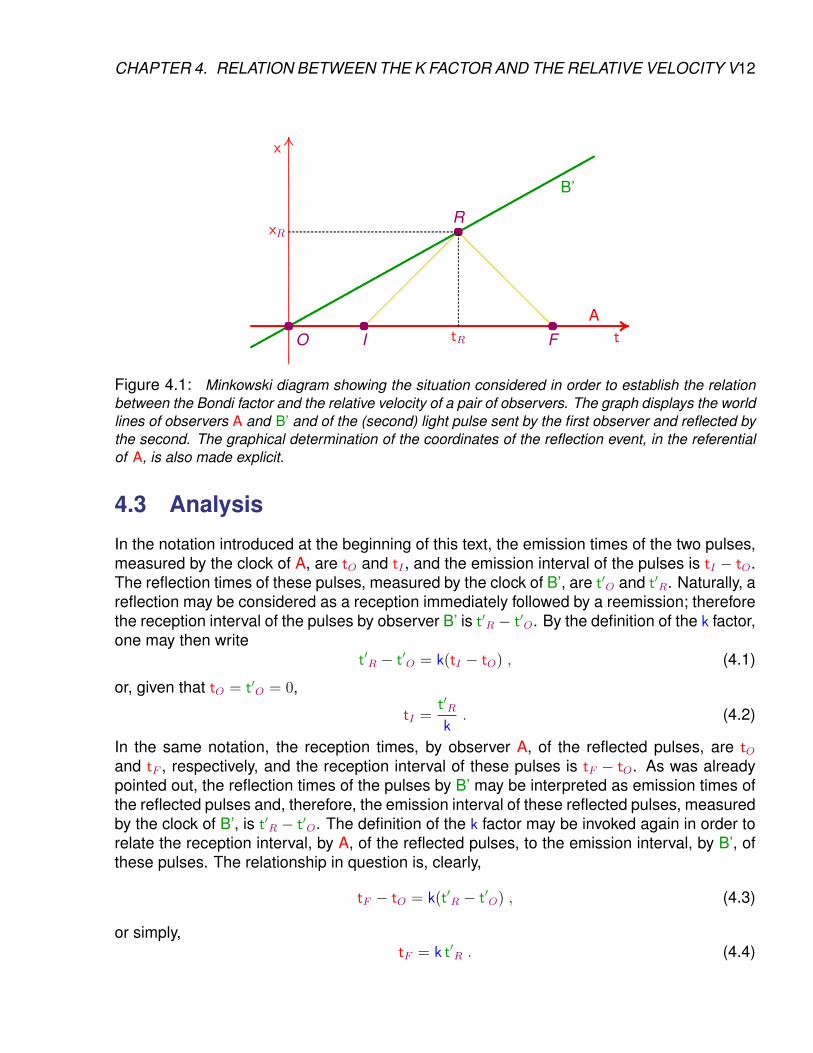
F..........................................................................................................................................................................................................................................................................................
Figure 4.1: Minkowski diagram showing the situation considered in order to establish the relationbetween the Bondi factor and the relative velocity of a pair of observers. The graph displays the worldlines of observers A and B’ and of the (second) light pulse sent by the first observer and reflected bythe second. The graphical determination of the coordinates of the reflection event, in the referentialof A, is also made explicit.
4.3 Analysis
In the notation introduced at the beginning of this text, the emission times of the two pulses,measured by the clock of A, are tO and tI , and the emission interval of the pulses is tI − tO.The reflection times of these pulses, measured by the clock of B’, are t′O and t′R. Naturally, areflection may be considered as a reception immediately followed by a reemission; thereforethe reception interval of the pulses by observer B’ is t′R − t′O. By the definition of the k factor,one may then write
t′R − t′O = k(tI − tO) , (4.1)
or, given that tO = t′O = 0,
tI =t′Rk. (4.2)
In the same notation, the reception times, by observer A, of the reflected pulses, are tOand tF , respectively, and the reception interval of these pulses is tF − tO. As was alreadypointed out, the reflection times of the pulses by B’ may be interpreted as emission times ofthe reflected pulses and, therefore, the emission interval of these reflected pulses, measuredby the clock of B’, is t′R − t′O. The definition of the k factor may be invoked again in order torelate the reception interval, by A, of the reflected pulses, to the emission interval, by B’, ofthese pulses. The relationship in question is, clearly,
tF − tO = k(t′R − t′O) , (4.3)
or simply,tF = k t′R . (4.4)
CHAPTER 4. RELATION BETWEEN THE K FACTOR AND THE RELATIVE VELOCITY V13
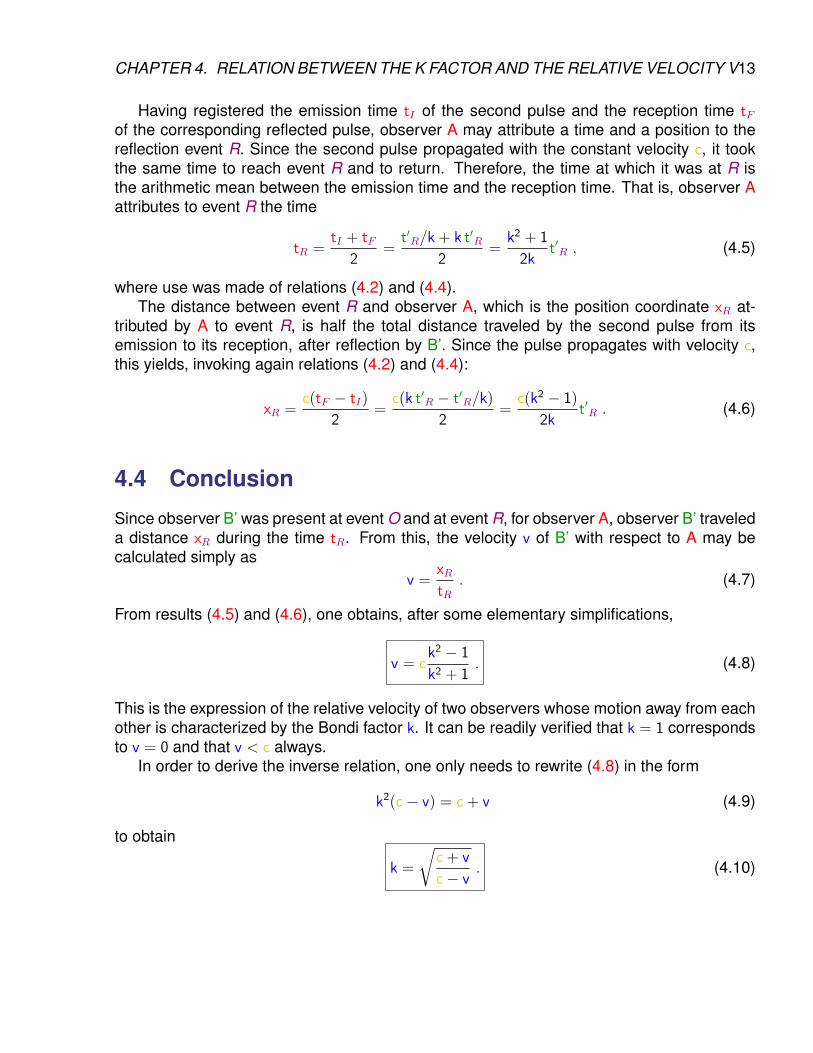
Having registered the emission time tI of the second pulse and the reception time tFof the corresponding reflected pulse, observer A may attribute a time and a position to thereflection event R. Since the second pulse propagated with the constant velocity c, it tookthe same time to reach event R and to return. Therefore, the time at which it was at R isthe arithmetic mean between the emission time and the reception time. That is, observer Aattributes to event R the time
tR =tI + tF
2=
t′R/k + k t′R2
=k2 + 1
2kt′R , (4.5)
where use was made of relations (4.2) and (4.4).The distance between event R and observer A, which is the position coordinate xR at-
tributed by A to event R, is half the total distance traveled by the second pulse from itsemission to its reception, after reflection by B’. Since the pulse propagates with velocity c,this yields, invoking again relations (4.2) and (4.4):
xR =c(tF − tI)
2=
c(k t′R − t′R/k)
2=
c(k2 − 1)
2kt′R . (4.6)
4.4 Conclusion
Since observer B’ was present at event O and at event R, for observer A, observer B’ traveleda distance xR during the time tR. From this, the velocity v of B’ with respect to A may becalculated simply as
v =xRtR
. (4.7)
From results (4.5) and (4.6), one obtains, after some elementary simplifications,
v = ck2 − 1
k2 + 1. (4.8)
This is the expression of the relative velocity of two observers whose motion away from eachother is characterized by the Bondi factor k. It can be readily verified that k = 1 correspondsto v = 0 and that v < c always.
In order to derive the inverse relation, one only needs to rewrite (4.8) in the form
k2(c− v) = c + v (4.9)
to obtain
k =
√c + v
c− v. (4.10)
CHAPTER 4. RELATION BETWEEN THE K FACTOR AND THE RELATIVE VELOCITY V14
4.5 Comments
The relationship between the Bondi factor k and the relative velocity v obtained in the previ-ous section is valid in the case of two observers who are moving away from each other.
As shown in the previous chapter, if the observers were moving towards each other, theBondi factor would be
k =1
k=
√c− v
c + v. (4.11)
Expressions (4.10) e (4.11) are encountered in the majority of Relativity textbooks in thediscussion of the Doppler effect1 for light (or for an electromagnetic wave in general), for thesituations in which the detector moves away or towards the source, respectively.
It may be worth while to emphasize that the quantity v considered here is, to be precise,the modulus or absolute value of the relative velocity of the observers. A more conventionalapproach consists in attributing arbitrarily a positive sense to the line of motion of the secondobserver with respect to the first and in considering v > 0 if the sense of motion coincideswith this arbitrary sense and v < 0 if they are opposite. Such an attribution specifies therelative motion by the value of v ∈]− c,+c[, for the whole duration of the motion, withoutdistinguishing between the situations in which the observers are moving away or towardeach other. In contrast, in Bondi’s approach, which is used in this text, if the relative motion isspecified by k > 1 in the phase of the motion when the observers are moving away from eachother, the same motion had to be specified by k = 1/k < 1 in the phase of approximation ofthe observers.
1In the form presented here, these expressions give the ratio between the periods of reception and emission.If one considers frequencies rather than periods, the expressions are exchanged, since frequency is the inverseof period.
Chapter 5
Time dilation
5.1 Introduction
One frequently hears the affirmation that Einstein established that time is relative. A moreprecise statement would be that observers in relative motion will attribute different values tothe interval of time between two events. For example, if an observer compares to his ownclock the clock carried by an other observer in motion with respect to him, he will concludethat the moving clock is running slow, for the interval between ticks of the moving clock islarger than the interval between ticks of his own clock. The ratio between these intervals isa simple function of the Bondi factor - or the velocity - which characterizes the motion of oneobserver with respect to the other.
5.2 Situation
The situation to be considered is the same as in the previous chapter and is represented inthe Minkowski diagram of Figure 4.1. The pair of events of interest are two ticks of the clockcarried by observer B’. The first tick occurs at event O, when the observers pass by eachother. The second tick occurs when the second light pulse is reflected by the mirror carriedby B’, that is, at event R.
As in the previous chapter, it is convenient to suppose that the observers both reset theirclocks to zero when they pass by each other, so that the clocks both indicate zero time whenthe first tick occurs: tO = t′O = 0. The time indicated by the clock of B’ when the second tickoccurs is denoted by t′R and the time attributed by observer A to this event is denoted by tR.The interval between the ticks is therefore t′R by the clock of B’ and tR by the clock of A. Theratio tR/t′R between these intervals is the quantity of interest. If time were universal, flowingequally for all observers, this ratio would be, evidently, equal to unity.
15
CHAPTER 5. TIME DILATION 16
5.3 Analysis
Since the second tick of the clock carried by observer B’ coincides with event R, the timeindicated by the clock of observer A when it happens is the time attributed by A to event R,which was already calculated in the previous chapter, with the result [see expression (4.5)]
tR =t′R/k + k t′R
2. (5.1)
The ratio between the intervals separating the ticks, as measured by each observer, is there-fore
tRt′R
=1/k + k
2≡ γ , (5.2)
where the conventional notation γ was introduced for this important quantity, known as theLorentz factor. Using expression (4.10) previously obtained for the k factor in terms of therelative velocity v, it is easy to obtain the expression of the Lorentz factor in terms of v:
γ =1
2(
√c− v
c + v+
√c + v
c− v) =
c√c2 − v2
, (5.3)
or
γ =1√
1− v2/c2. (5.4)
Naturally, γ = 1 if the observers are at rest with respect to each other. For observers inrelative motion, γ > 1 always and the γ factor grows indefinitely when the relative velocity ofthe observers approaches the velocity of light.
5.4 Summary
In order to express in a more general notation the result obtained above, it is convenient toadopt the Greek letter ∆ to indicate an interval of variation of some quantity. For example,the notation ∆t′ indicates the variation (in this case, between events O and R) of the timeindicated by the clock carried by observer B’ and the expression ∆t refers to the variationof the time marked by the clock of observer A (between the same pair of events). In thedevelopment above, one has ∆t′ = t′R and ∆t = tR. Therefore, relation (5.2) takes the form
∆t = γ∆t′ . (5.5)
The essential difference between observers B’ and A is that, for the first, the clock whoseticks are the events of interest is at rest whereas, for the second, that clock is moving withvelocity v. In order to emphasize this essential point, it is convenient to use the notation ∆t0for the time interval indicated by the clock at rest and the notation ∆tv for the correspondinginterval, measured by the clock of an observer who sees the first clock moving with velocity v.In the situation analyzed above, one has then ∆t′ = ∆t0 and ∆t = ∆tv, so that relation (5.5)reads
∆tv = γ∆t0 with γ =1√
1− v2/c2> 1 . (5.6)
CHAPTER 5. TIME DILATION 17
The phrasing proper time interval is frequently used in reference to ∆t0, the time intervalbetween ticks of a clock, measured in a referential in which this clock is at rest.
5.5 Conclusion
Watching the pointer’s rotation of a moving clock, an observer notes that it indicates atime interval ∆t0. Comparing with the pointer’s rotation of the clock at his wrist, he no-tices that it does not correspond to the same time interval, but to interval ∆tv, such that∆tv = γ∆t0 > ∆t0. Trusting, evidently, his own clock, he concludes that the moving clockis running slow. This phenomenon is known as time dilation.
It is worth while to emphasize the following points:
• It can be easily verified that expression (5.2) is invariant under the exchange k↔ 1/kand, therefore, for a given value of the relative velocity, time dilation is the same whenthe two observers are moving toward each other as when they are moving apart. Thisdifference between the Doppler effect and time dilation should be stressed: in theDoppler effect, one observes an increase in the period when the source is movingaway and a decrease in the period when the source is getting closer; in contrast, thepassage of time is subject to dilation only, time compression never occurs.
• The effect is reciprocal. For B’, it is the clock carried by A which is moving and is,therefore, running slow.
• From a theoretical point of view, time dilation is an irrefutable consequence of thepostulates of Relativity.
5.6 Illustration
Time dilation is verified experimentally, for example in the decay times of unstable particlesproduced by cosmic rays when they impinge on the Earth’s atmosphere. One can imaginethat such particles possess an “internal clock” which determines their proper lifetimes ∆t0.In the referential of the Earth, the particles propagate with velocity v close (although inferior)to the speed of light. The time they take to traverse the atmosphere is ∆t = H/v, whereH is the atmosphere’s height, measured in the referential of the Earth.1 It turns out that∆t > ∆t0, so that, if time dilation did not occur, the particles would vanish before they couldbe detected in laboratories installed on the Earth’s surface. But thanks to time dilation, thelifetime of these particles in the Earth’s referential is ∆tv, much larger than ∆t0, since theLorentz factor γ is much larger than unity. For a particle with velocity sufficiently close to thespeed of light, ∆tv will be larger than ∆t and the particle will survive long enough to crossthe whole atmosphere and be detected at ground level.
1The importance of stating explicitely in what referential a height, or a length, is measured, is the topicdiscussed in the next chapter.
Chapter 6
Length contraction
6.1 Introduction
In order to establish the geometry of space, it is necessary to give meaning to the distancebetween two points or, more concretely, to the length of a rigid object. If the object is atrest, there is no difficulty. For example, if an observer is on a platform which is at rest, hewill be able to determine its length by walking from an extremity to the other and countingthe number of steps. Since the platform is not moving, there is no need to worry about thesimultaneity of the events used in the measurement, the observer may take all the time hewants to complete the walk. Naturally, for a more precise determination, use can be madeof the fundamental principles of physics and, in particular, of the invariance of the speed oflight. One may set a mirror at one of the platform’s extremities and, from the other extremity,send a light pulse to be reflected by the mirror. Letting E be the pulse’s emission event andD the event of detection of the reflected pulse, the length of the platform will be given byL0 = c tD−tE
2, where c is the speed of light and the times tD and tE are measured by the clock
of the observer who is at rest on the platform. The length thus determined is known as restlength, or proper length of the platform, since it is measured by an observer who is at restrelative to the platform.
When the object whose length is to be measured is moving with respect to the observerwho will perform the measurement, care must be taken to guarantee that the events se-lected at each extremity of the object, in order to calculate the distance between them, occursimultaneously for the observer in question.
6.2 Situation
Observer A wishes to determine the length L (for him) of a platform which is moving withvelocity v, corresponding to the Bondi factor k. Two observers B’ and C’ are at rest on theplatform, each at an extremity. Both carry a mirror. For them, the platform’s length is L′.Since the platform is at rest with respect to these observers, this is the proper length L0
of the platform. One has, then, L′ = L0. One may assume that this length was previouslymeasured by B’, for example, by sending a light pulse to the mirror of C’ and detecting the
18
CHAPTER 6. LENGTH CONTRACTION 19
reflected pulse, following the procedure described in Section 6.1. One may further assumethat B’ communicated the result to A.
In order to determine the length of the platform, as observed by him, A needs to calculatethe distance between two events occurring simultaneously (for him) at each extremity of theplatform. These events shall be reflections of light pulses by the mirrors.
It shall be assumed that B’ passes by A before C’ and, in order to simplify the arguments,it shall be further assumed that, when C’ passes by A, both reset their clocks to zero. Onemay imagine that A sends a pulse to C’ at that event; this pulse (which shall be referred to aspulse 0) is received and reflected instantaneously by C’, and the reflected pulse is receivedinstantaneously by A. In other words, the events of emission, reflection and reception of thispulse 0 all coincide and this event will be denoted by O. By notational convention, tO shallrepresent the time attributed by observer A to this event and t′O shall represent the timeattributed by observer C’ to the same event. In the conditions stated above, tO = t′O = 0.Evidently, the clock carried by B’ should also be reset so that, for B’ and C’, their clocks willalways indicate the same time, since they are at rest with respect to each other.
..........
..........
..........
..........
..........
..........
..........
..........
..........
..........
..........
..........
..........
..........
..........
..........
..........
..........
..........
..........
..........
..........
..........
..........
..........
..........
..........
..........
..........
..........
..........
..........
..........
..........
..........
..........
..........
..........
..........
..........
..........
..........
..........
..........
..........
..........
..........
..........
..........
.........................
.................x
................................................................................................................................................................................................................................................................................................................................................................................................................................................................................................................................................................................................................................................................................................................................................................................................................................ .................At....................................................
........................................................................................................
........................................................................................................
........................................................................................................
........................................................................................................
........................................................................................................
........................................................................................................
.......................................................................................
........................................................................................................
........................................................................................................
........................................................................................................
........................................................................................................
........................................................................................................
........................................................................................................
........................................................................................................
...................................B’
C’
............................
............................
............................
............................
............................
............................
............................
............................
............................
............................
............................
............................
............................
............................
........................................................................................................................................................................................................................................................................................................................................................................................................................................................
............................
............................
............................
............................
............................
.............................................................................................................................................................................................
...........................
.................................................................................
...........................
...........................
O,I
R
FJ
S
G
P
................................................................................................................................................................................................................................................
............................................................................................................................................................................................................
.................................................................................
.......
.....
.......
.....
.......
.....
.......
............
...........
.......
.....
.......
.....
.......
................
...........
...................................................
.......................................................................................................
.......
.....
.......
.....
.......
.....
.......
.....
.......
.....
.......
.....
.......
................
...........
dR
dS
L
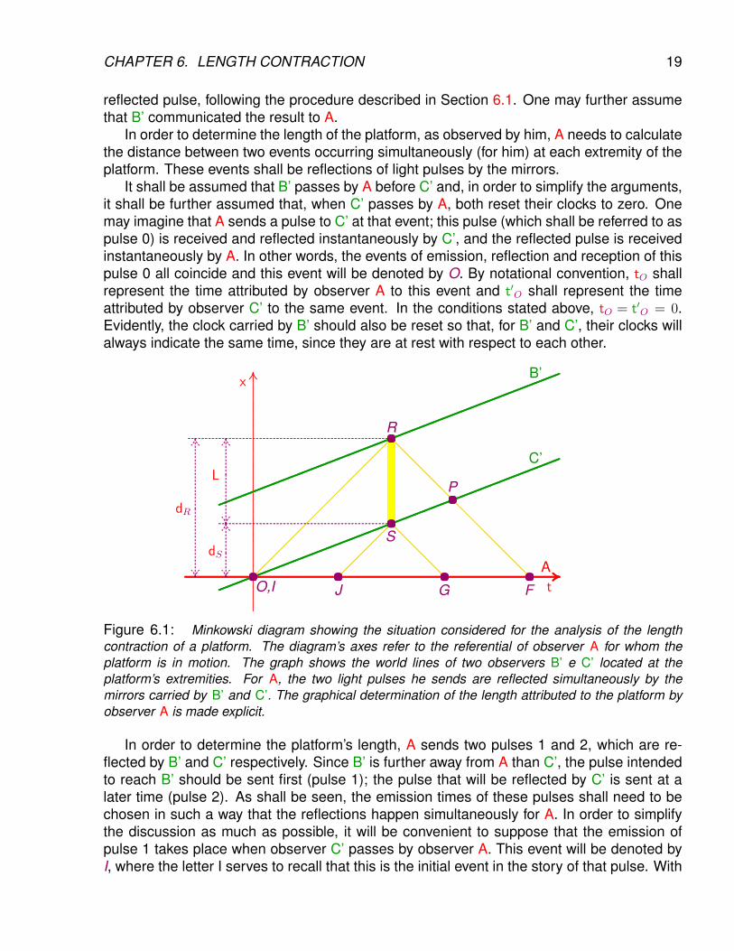
Figure 6.1: Minkowski diagram showing the situation considered for the analysis of the lengthcontraction of a platform. The diagram’s axes refer to the referential of observer A for whom theplatform is in motion. The graph shows the world lines of two observers B’ e C’ located at theplatform’s extremities. For A, the two light pulses he sends are reflected simultaneously by themirrors carried by B’ and C’. The graphical determination of the length attributed to the platform byobserver A is made explicit.
In order to determine the platform’s length, A sends two pulses 1 and 2, which are re-flected by B’ and C’ respectively. Since B’ is further away from A than C’, the pulse intendedto reach B’ should be sent first (pulse 1); the pulse that will be reflected by C’ is sent at alater time (pulse 2). As shall be seen, the emission times of these pulses shall need to bechosen in such a way that the reflections happen simultaneously for A. In order to simplifythe discussion as much as possible, it will be convenient to suppose that the emission ofpulse 1 takes place when observer C’ passes by observer A. This event will be denoted byI, where the letter I serves to recall that this is the initial event in the story of that pulse. With
CHAPTER 6. LENGTH CONTRACTION 20
this convention, event I coincides, in fact, with event O and one has tI = t′I = 0. The eventof reflection of pulse 1 by B’ will be denoted by R and the event of reception by A of thecorresponding reflected pulse will be denoted by F, where the letter F reminds the reader ofthe fact that this is the final event in this pulse’s history.
Pulse 2, which will be reflected by C’, is sent by A some time later. In analogy with theevent succession I → R→ F in the history of pulse 1, the sequence J → S → G will refer tothe important events in the history of pulse 2, that is, J shall denote the event of emission ofthis pulse and G the event of reception by A of the corresponding reflected pulse. The letterS will be used to indicate the event of reflection of this pulse by observer C’.
The Minkowski diagram illustrating the situation described above is presented in Fig-ure 6.1.
6.3 Analysis
The events of emission, by observer A, of pulses 0 and 2 are O and J, respectively. There-fore, the emission interval of these pulses, measured by the clock of A, is tJ − tO. Thereception events of these pulses by observer C’ are O and S, respectively. Therefore, thereception interval of these pulses, measured by the clock of C’, is t′S − t′O. By definition ofthe Bondi factor
t′S − t′O = k(tJ − tO) , (6.1)
or simply, given that tO = t′O = 0,t′S = k tJ . (6.2)
Observer C’ sends the reflected pulse 0 at event O and the reflected pulse 2 at event S.Therefore, the emission time interval of these reflected pulses is t′S − t′O. The receptionevents, by A, of these reflected pulses are O and G, respectively. The reception interval ofthese reflected pulses is therefore, tG − tO. Invoking again the definition of the Bondi factor,one may write
tG − tO = k(t′S − t′O) , (6.3)
or, recalling once more that tO = t′O = 0,
tG = k t′S = k2 tJ , (6.4)
where use was made of relation (6.2).One may now focus the attention on pulse 1. After reflection by B’, it passes by C’ on its
way back to A, an event one may denote by P. The detection, by C’, of the pulse that passesby him may be considered as a reception followed by immediate reemission. Therefore, onemay consider that observer C’ emitted pulses at the events O (the pulse 0) and P (the pulse1 detected on its way back to A). The emission interval of these pulses is t′P − t′O. Thesepulses are received by A at events O and F, respectively. The reception interval, measuredby the clock of the receiver, is then tF − tO. Using again the definition of the Bondi factor,one may write
tF − tO = k(t′P − t′O) , (6.5)
or simply,tF = k t′P . (6.6)
CHAPTER 6. LENGTH CONTRACTION 21
Between events I and P, pulse 1 went from C’ to B’ and back to C’. From the point of view ofC’ and B’, it traveled a distance 2 L′ between instants t′I and t′P ; therefore, one has
2 L′ = c(t′P − t′I) = c t′P , (6.7)
since t′I = 0. From (6.6) and (6.7), one gets
tF =2 k L′
c. (6.8)
Since light takes the same time to go from A to B’ and to come back, observer A attributesto the event of reflection of pulse 1 by B’ the time
tR =tI + tF
2=
k L′
c, (6.9)
where use was made of relation (6.8), remembering that tI = 0. By the same argument,observer A attributes to the event of reflection of pulse 2 by C’ the time
tS =tJ + tG
2=
1 + k2
2tJ , (6.10)
where relation (6.4) was used.In order that the above procedure constitute a measurement, by A, of the platform’s
length, observer A must send the second pulse at the instant such that the events utilizedin the measurement, that is, the reflection events R and S at the two extremities of theplatform, be simultaneous (for him, observer A). In other words, he needs to choose thetime tJ at which he emits the second pulse in such a way as to fulfill the condition tS = tR,which, by (6.9) and (6.10), requires
tJ =2 k L′
(1 + k2)c. (6.11)
By assumption, observer A knows the values of the Bondi factor k which characterizes themotion of the platform relative to himself and the length L′, which was measured and com-municated by the observers at rest on the platform. Therefore, observer A can perform thecalculation (6.11) and send pulse 2 at the right moment.
One may denote by dR and dS the distances, with respect to observer A, of the placesof occurrence of events R and S, respectively. Since light always propagates with velocity c,one has, using (6.8) and recalling that tI = 0 by choice:
2 dR = c(tF − tI) = 2 k L′ . (6.12)
Similarly, using (6.4) and (6.11), one has
2 dS = c(tG − tJ) = c(k2 − 1)tJ =2 k(k2 − 1)
k2 + 1L′ . (6.13)
The length attributed to the platform by observer A will then obviously be
L = dR − dS = (1− k2 − 1
k2 + 1)k L′ =
2k
k2 + 1L′ . (6.14)
CHAPTER 6. LENGTH CONTRACTION 22
Recalling the relationship previously obtained between the Bondi factor k and the velocityv for two observers moving away from each other, namely [equation (4.10)],
k =
√c + v
c− v, (6.15)
it can be easily verified that2k
k2 + 1=
√1− v2
c2=
1
γ, (6.16)
where γ is the (already well known) Lorentz factor.
6.4 Summary
Inserting the result (6.16) in relation (6.14), one concludes that
L =L′
γ. (6.17)
The essential difference between observers B’ and A is that, for the first, the platform whoselength is being measured is at rest, whereas, for the second, it is moving with velocity v. Inorder to emphasize this essential point, it is convenient to employ the notation L0 (alreadyintroduced above) for the length of the platform at rest and the notation Lv for the corre-sponding length, measured by an observer who sees the platform moving with velocity v. Inthe situation analyzed above, one has then L′ = L0 and L = Lv, so that relation (6.17) reads
Lv =L0
γwith γ =
1√1− v2/c2
> 1 . (6.18)
As already mentioned, the expression proper length is frequently used in reference to L0,the length of the platform, or of any other object, measured in the referential in which theobject in question is at rest.
6.5 Conclusion
Generalizing the above result, it may be stated that to someone who observes a movingobject, this object appears contracted in the direction of its motion. This phenomenonis known as length contraction or Lorentz contraction, in homage to the physicist who firstintroduced it, although on the basis of arguments significantly different from those pertinentto Einstein’s theory of Special Relativity.
The following points deserve to be emphasized:
• For this effect, it is irrelevant whether the moving object is getting closer or more distant,since the γ factor is the same in both situations, for a given value of the relative velocityv.
CHAPTER 6. LENGTH CONTRACTION 23
• The effect is reciprocal: an object at rest with respect to observer A would seem con-tracted, by the same γ factor, to observers B’ and C’.
• It is a real kinematic effect, not an illusion related to the observation of the object withlight.
6.6 Illustration
The propagation toward the Earth’s surface and the detection of unstable particles producedby cosmic rays entering the atmosphere, that were mentioned at the end of the previouschapter as an illustration of time dilation, may also be analyzed invoking length contraction.
For this purpose, one needs only adopt the point of view of an observer who accompa-nies a particle propagating, with velocity v, from the atmosphere’s upper region to groundlevel. For consistency with the conventions adopted in the discussion of the previous chap-ter, this observer shall be called B’ and the observer at rest on the Earth’s surface shall becalled A. Because of length contraction, the observer who rides with the particle sees theground (and therefore also the detector), initially at a distance H′ = Hv = H0/γ, where H0 ≡ His the atmosphere’s height measured by the terrestrial observer A and γ is the Lorentz fac-tor associated with velocity v. Since the ground is approaching with velocity v, the detectorin the terrestrial laboratory takes the time interval ∆t′ = H′/v = Hv/v = H0/(γv) to reach theparticle. If velocity v is sufficiently close to the speed of light, the Lorentz factor γ will bevery large and the interval ∆t′ will be less than the proper lifetime ∆t0 of the particle. Con-sequently, the particle will be reached by the detector before it decays and its detection willoccur.
Chapter 7
Combination of velocities
7.1 Introduction
According to the familiar understanding of velocity, the combination law for velocities associ-ated to motions in the same direction is simple arithmetic addition. For example, somebodywalking at 5 km/h on a belt rolling at 3 km/h is moving at the velocity of 8 km/h with respectto the airport hall. It is easy to perceive that this law must lose its validity when velocities areappreciable fractions of the speed of light, for it could lead to a resulting velocity larger thanthe speed of light, which is not allowed in Special Relativity.
In this chapter, the relativistic law of velocity combination is deduced, in the special caseof parallel velocities. The combination of Bondi factors, which follows almost trivially fromthe definition, is obtained first. On the basis of this law and of the relation between Bondifactor and velocity, already established in Chapter 4, the desired result is easily obtained.
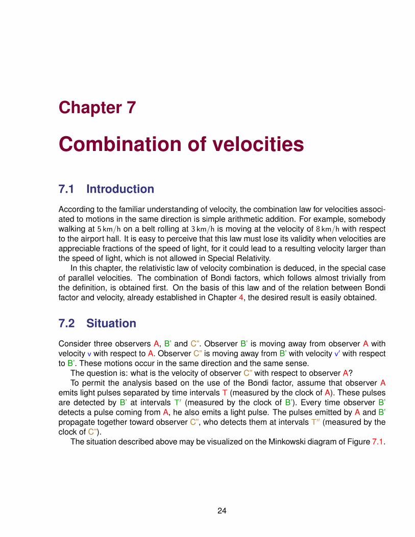
7.2 Situation
Consider three observers A, B’ and C”. Observer B’ is moving away from observer A withvelocity v with respect to A. Observer C” is moving away from B’ with velocity v′ with respectto B’. These motions occur in the same direction and the same sense.
The question is: what is the velocity of observer C” with respect to observer A?To permit the analysis based on the use of the Bondi factor, assume that observer A
emits light pulses separated by time intervals T (measured by the clock of A). These pulsesare detected by B’ at intervals T′ (measured by the clock of B’). Every time observer B’detects a pulse coming from A, he also emits a light pulse. The pulses emitted by A and B’propagate together toward observer C”, who detects them at intervals T′′ (measured by theclock of C”).
The situation described above may be visualized on the Minkowski diagram of Figure 7.1.
24
CHAPTER 7. COMBINATION OF VELOCITIES 25
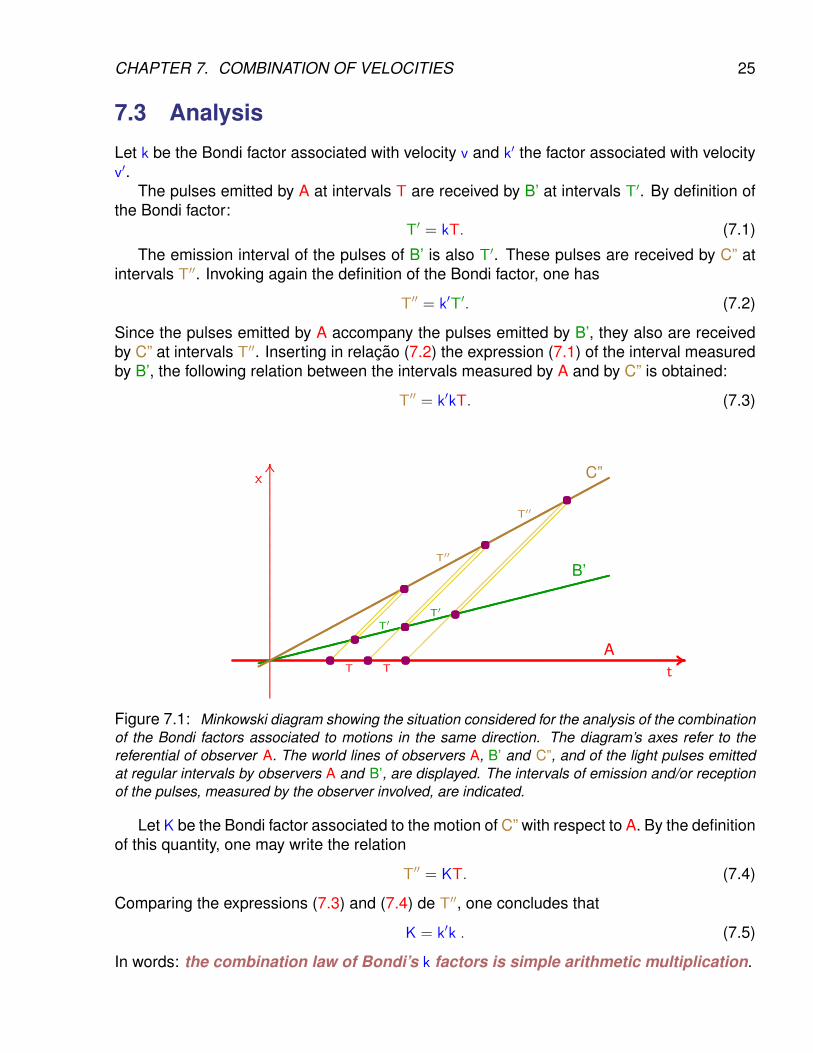
7.3 Analysis
Let k be the Bondi factor associated with velocity v and k′ the factor associated with velocityv′.
The pulses emitted by A at intervals T are received by B’ at intervals T′. By definition ofthe Bondi factor:
T′ = kT. (7.1)
The emission interval of the pulses of B’ is also T′. These pulses are received by C” atintervals T′′. Invoking again the definition of the Bondi factor, one has
T′′ = k′T′. (7.2)
Since the pulses emitted by A accompany the pulses emitted by B’, they also are receivedby C” at intervals T′′. Inserting in relacao (7.2) the expression (7.1) of the interval measuredby B’, the following relation between the intervals measured by A and by C” is obtained:
T′′ = k′kT. (7.3)
..........
..........
..........
..........
..........
..........
..........
..........
..........
..........
..........
..........
..........
..........
..........
..........
..........
..........
..........
..........
..........
..........
..........
..........
..........
..........
..........
..........
..........
..........
..........
..........
..........
..........
..........
..........
..........
..........
..........
..........
..........
..........
..........
..........
...................
.................x
....................................................................................................................................................................................................................................................................................................................................................................................................................................................................................................................................................................................................................................................................................................................................................................................................................................................................................................... .................At
..........................................................................................................................................................
..........................................................................................................................................................
..........................................................................................................................................................
..........................................................................................................................................................
..................................................................B’
................................................................................
................................................................................
................................................................................
................................................................................
................................................................................
................................................................................
................................................................................
................................................................................
................................................................................
................................C”
............................
............................
............................
............................
............................
............................
....................
............................
............................
............................
............................
............................
............................
............................
............................
............................
............................
..........................
............................
............................
............................
............................
............................
............................
............................
............................
............................
............................
............................
............................
............................
............................
............................
...
............................
............................
............................
............................
.....................
............................
............................
............................
............................
............................
............................
............................
......................
............................
............................
............................
............................
............................
............................
............................
............................
............................
............................
......................
....................... ....................... .............................................. ....................... ..............................................
..............................................
T T
T′T′
T′′
T′′
Figure 7.1: Minkowski diagram showing the situation considered for the analysis of the combinationof the Bondi factors associated to motions in the same direction. The diagram’s axes refer to thereferential of observer A. The world lines of observers A, B’ and C”, and of the light pulses emittedat regular intervals by observers A and B’, are displayed. The intervals of emission and/or receptionof the pulses, measured by the observer involved, are indicated.
Let K be the Bondi factor associated to the motion of C” with respect to A. By the definitionof this quantity, one may write the relation
T′′ = KT. (7.4)
Comparing the expressions (7.3) and (7.4) de T′′, one concludes that
K = k′k . (7.5)
In words: the combination law of Bondi’s k factors is simple arithmetic multiplication.
CHAPTER 7. COMBINATION OF VELOCITIES 26
7.4 Conclusion
Let V be the velocity of observer C” with respect to observer A. Making use of relation-ship (4.8), one obtains the expression of velocity V in terms of the Bondi factor K:
V = cK2 − 1
K2 + 1. (7.6)
Substituting in this relation the expression (7.5) of K in terms of k′ and k and then insertingthe expressions of these in terms of v′ and v, given by formula (4.10), one has
V = ck′2k2 − 1
k′2k2 + 1= c
c+v′
c−v′ ×c+vc−v − 1
c+v′
c−v′ ×c+vc−v + 1
= cv′c + vc
c2 + v′v, (7.7)
or, finally,
V =v′ + v
1 + v′vc2
, (7.8)
which constitutes the relativistic composition law for collinear velocities.
7.5 Comments
The above formula makes evident the following properties:
• V = c if v = c or v′ = c, which corresponds to the invariance of the speed of light: ifa body or signal moves with the velocity of light for one observer, it moves with thevelocity of light for all observers.1
• V is always smaller than c if v and v′ are small than c: if a body or signal moves withvelocity inferior to the velocity of light for one observer, it moves with a velocity inferiorto the velocity of light for all observers.
• If velocities v and v′ are both much smaller than the velocity of light c, the secondterm in the denominator of expression (7.8) will be much smaller than unity and therelativistic combination rule for velocities will be reduced, in very good approximation,to the familiar law of additive combination, V ' v′ + v.
1Since v e v′ are relative velocities of two observers, they cannot be put exactly equal to c; however, onemay consider velocities arbitrarily close to c.
Chapter 8
Twin paradox
8.1 Introduction
In Chapter 5, it was seen that a clock in uniform motion runs slow compared to the clockcarried by an inertial observer who witnesses the motion. This result may be applied tothe aging of a person, considered to be governed by an internal biological clock. If oneimagines a pair of twins born on Earth but who, someday, separate because one of themdecides to embark on a long trip to somewhere else in the Universe, one concludes thatthe twin who remains on Earth must think that his brother is aging more slowly than himself.However, since time dilation is a reciprocal effect, for the traveler, it should be his brother,who remained on Earth, who is keeping younger. As long as the twins are far away fromeach other, both can be right without manifest conflict since they cannot compare objectivelytheir physical and mental states.
But suppose that, after a few years, the traveling twin decides to return home. When thetwins meet again, the comparison will be possible and if one of the brothers is really youngerthan the other, both will have to agree that this is the case. The present chapter is devotedto the intriguing question.
8.2 Situation
Consider three observers A, B’ and C”. Observer B’ is moving with velocity v with respectto observer A. Observer C” is also moving with velocity v with respect to observer A, in thesame direction but in the opposite sense.
Initially, B’ and C” are getting closer to A; B’ is already near A but C” is still far away.When B’ passes by A, both reset their clocks to zero. Denoting by O this event, one hasthen tO = t′O = 0. At the said event, observer B’ sends a first light pulse to A, who receivesit essentially instantaneously, since A and B’ are at the same spot.
Observer B’ begins then to move away from A and toward C”. The meeting of observersB’ e C” shall be named event P . At this event, observer C” adjusts his clock in accordancewith that of B’, so that t′′P = t′P . As they cross, observers B’ and C” both send light pulsesto A. These pulses travel together and are received by A at the same event, which will bedenoted by R.
27
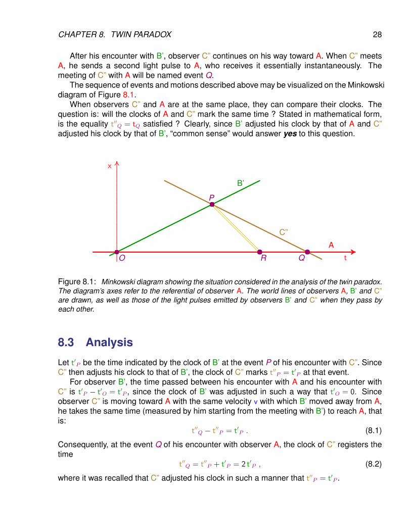
CHAPTER 8. TWIN PARADOX 28
After his encounter with B’, observer C” continues on his way toward A. When C” meetsA, he sends a second light pulse to A, who receives it essentially instantaneously. Themeeting of C” with A will be named event Q.
The sequence of events and motions described above may be visualized on the Minkowskidiagram of Figure 8.1.
When observers C” and A are at the same place, they can compare their clocks. Thequestion is: will the clocks of A and C” mark the same time ? Stated in mathematical form,is the equality t′′Q = tQ satisfied ? Clearly, since B’ adjusted his clock by that of A and C”adjusted his clock by that of B’, “common sense” would answer yes to this question.
..........
..........
..........
..........
..........
..........
..........
..........
..........
..........
..........
..........
..........
..........
..........
..........
..........
..........
..........
..........
..........
..........
..........
..........
..........
..........
..........
..........
..........
..........
..........
..........
..........
..........
..........
..........
..........
.....................
.................x
.................................................................................................................................................................................................................................................................................................................................................................................................................................................................................................................................................................................................................................................................................................................................................................................................................................................................................................................................................................................................................................... .................At..........................................
....................................................................................
....................................................................................
....................................................................................
....................................................................................
....................................................................................
....................................................................................
.................................................................................B’.................................................................................................................................................................................................................................................................................................................................................................................................................................................................................................................................................................................................................................................................................
C”
............................................................................................................................................................................................................................................................
...................................................................................................................................................................................................................................................................................
............................
............................ ............................O
P
R Q
Figure 8.1: Minkowski diagram showing the situation considered in the analysis of the twin paradox.The diagram’s axes refer to the referential of observer A. The world lines of observers A, B’ and C”are drawn, as well as those of the light pulses emitted by observers B’ and C” when they pass byeach other.
8.3 Analysis
Let t′P be the time indicated by the clock of B’ at the event P of his encounter with C”. SinceC” then adjusts his clock to that of B’, the clock of C” marks t′′P = t′P at that event.
For observer B’, the time passed between his encounter with A and his encounter withC” is t′P − t′O = t′P , since the clock of B’ was adjusted in such a way that t′O = 0. Sinceobserver C” is moving toward A with the same velocity v with which B’ moved away from A,he takes the same time (measured by him starting from the meeting with B’) to reach A, thatis:
t′′Q − t′′P = t′P . (8.1)
Consequently, at the event Q of his encounter with observer A, the clock of C” registers thetime
t′′Q = t′′P + t′P = 2 t′P , (8.2)
where it was recalled that C” adjusted his clock in such a manner that t′′P = t′P .
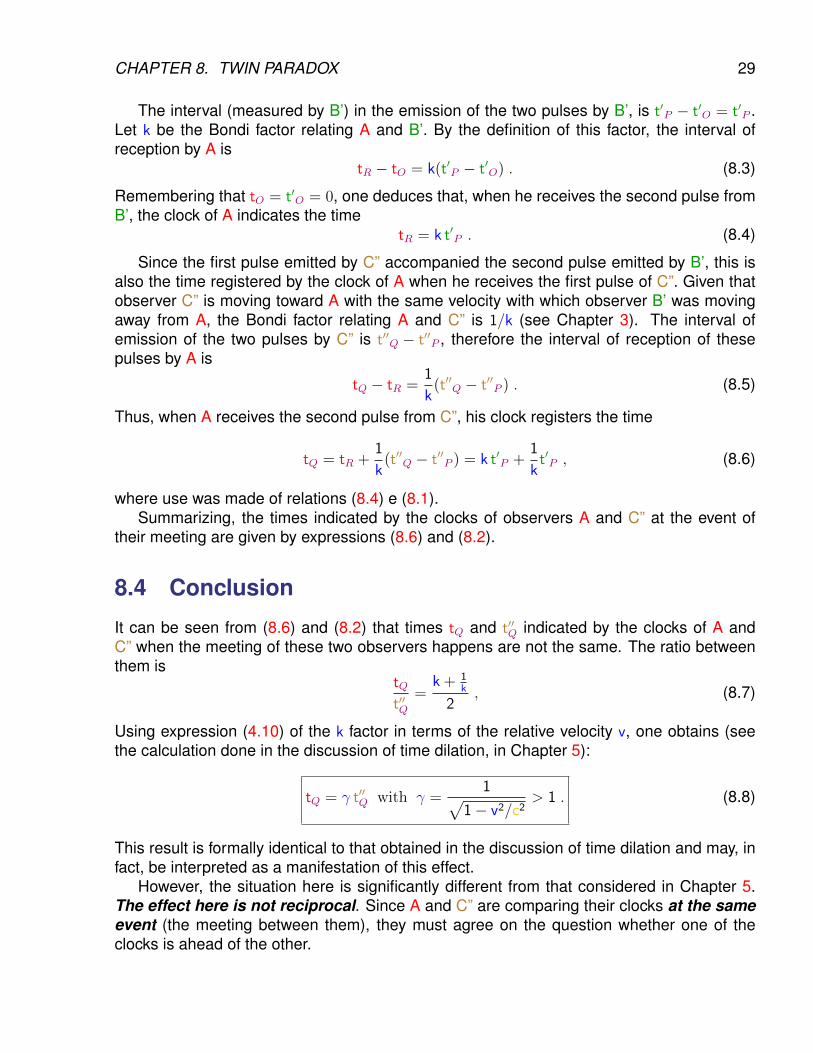
CHAPTER 8. TWIN PARADOX 29
The interval (measured by B’) in the emission of the two pulses by B’, is t′P − t′O = t′P .Let k be the Bondi factor relating A and B’. By the definition of this factor, the interval ofreception by A is
tR − tO = k(t′P − t′O) . (8.3)
Remembering that tO = t′O = 0, one deduces that, when he receives the second pulse fromB’, the clock of A indicates the time
tR = k t′P . (8.4)
Since the first pulse emitted by C” accompanied the second pulse emitted by B’, this isalso the time registered by the clock of A when he receives the first pulse of C”. Given thatobserver C” is moving toward A with the same velocity with which observer B’ was movingaway from A, the Bondi factor relating A and C” is 1/k (see Chapter 3). The interval ofemission of the two pulses by C” is t′′Q − t′′P , therefore the interval of reception of thesepulses by A is
tQ − tR =1
k(t′′Q − t′′P ) . (8.5)
Thus, when A receives the second pulse from C”, his clock registers the time
tQ = tR +1
k(t′′Q − t′′P ) = k t′P +
1
kt′P , (8.6)
where use was made of relations (8.4) e (8.1).Summarizing, the times indicated by the clocks of observers A and C” at the event of
their meeting are given by expressions (8.6) and (8.2).
8.4 Conclusion
It can be seen from (8.6) and (8.2) that times tQ and t′′Q indicated by the clocks of A andC” when the meeting of these two observers happens are not the same. The ratio betweenthem is
tQt′′Q
=k + 1
k
2, (8.7)
Using expression (4.10) of the k factor in terms of the relative velocity v, one obtains (seethe calculation done in the discussion of time dilation, in Chapter 5):
tQ = γ t′′Q with γ =1√
1− v2/c2> 1 . (8.8)
This result is formally identical to that obtained in the discussion of time dilation and may, infact, be interpreted as a manifestation of this effect.
However, the situation here is significantly different from that considered in Chapter 5.The effect here is not reciprocal. Since A and C” are comparing their clocks at the sameevent (the meeting between them), they must agree on the question whether one of theclocks is ahead of the other.
CHAPTER 8. TWIN PARADOX 30
8.5 Illustration
The above conclusion may be invoked to answer the question raised in the introduction tothis chapter.
Suppose observer A lives on Earth and is the father of twins John and Peter. Observer B’,an extraterrestrial being traveling in his spaceship, passes by A and picks John up, whereasPeter remains on Earth with A. After a few years of traveling, the spaceship of B’ passes byanother spaceship coming in the opposite direction, with the same velocity (with respect tothe Earth). In command of that spaceship is observer C”, another extraterrestrial. Longingfor home, John transfers himself to the spaceship of C” and, after a few more years oftraveling, he is back on Earth and re-encounters his father A and his brother Peter.
When A compares his reunited twins, he notices that John, who traveled, is nowyounger than Peter, who stayed home! Note that everyone has to agree on this. The sit-uation is not symmetric, for John jumped from one inertial referential to another, whereasPeter always remained in the same inertial referential. As he transfered himself from Earthto the first spaceship, from this to the second spaceship, and from the latter back to Earth,John necessarily underwent acceleration. In contrast, Peter was not submitted to any ac-celeration (to the extent that Earth may be considered as constituting an inertial referential1).
The drama imagined above belongs, for the time being, to the realm of science fictiononly. However, the physical effect that is involved is verified in high-precision experimentscomparing clocks carried by airplanes to clocks at rest on Earth.
1This assumption obviously disregards the Earth’s orbital motion about the Sun.
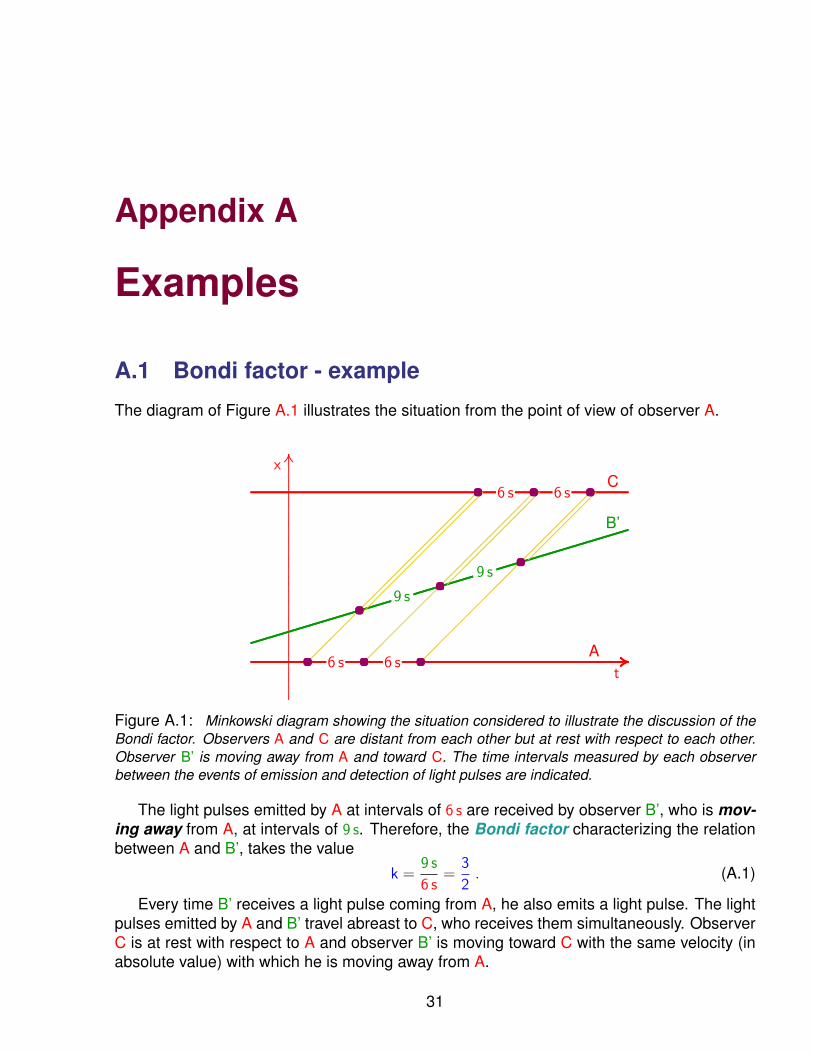
Appendix A
Examples
A.1 Bondi factor - example
The diagram of Figure A.1 illustrates the situation from the point of view of observer A.
..........
..........
..........
..........
..........
..........
..........
..........
..........
..........
..........
..........
..........
..........
..........
..........
..........
..........
..........
..........
..........
..........
..........
..........
..........
..........
..........
..........
..........
..........
..........
..........
..........
..........
..........
..........
..........
..........
..........
..........
..........
..........
..........
..........
..........
..........
....................
.................x
......................................................................................................................................................................................................................................................................................................................................................................................................................................................................................................................................................................................................................................................................................................................................................... .................A
........................................................................................................................................................................................................................................................................................................................................................................................................................................................................................................................................................................................................................................................................................................................................C
t
..................................................................................................................................
..................................................................................................................................
..................................................................................................................................
..................................................................................................................................
..................................................................................................................................
.............................................................................................B’
...........................................................................
6 s 6 s
6 s 6 s
9 s
9 s
............................
............................
............................
............................
............................
............................
............................
............................
............................
............................
............................
............................
............................
............................
............................
............................
.....
............................
............................
............................
............................
............................
............................
............................
............................
............................
............................
............................
............................
............................
............................
............................
............................
.....
............................
............................
............................
............................
............................
............................
............................
............................
............................
............................
............................
........
............................
............................
............................
............................
............................
............................
............................
............................
......................
............................
............................
............................
............................
............................
............................
.............
....................... ....................... .......................
....................... ....................... .......................
..............................................
.......................
Figure A.1: Minkowski diagram showing the situation considered to illustrate the discussion of theBondi factor. Observers A and C are distant from each other but at rest with respect to each other.Observer B’ is moving away from A and toward C. The time intervals measured by each observerbetween the events of emission and detection of light pulses are indicated.
The light pulses emitted by A at intervals of 6 s are received by observer B’, who is mov-ing away from A, at intervals of 9 s. Therefore, the Bondi factor characterizing the relationbetween A and B’, takes the value
k =9 s
6 s=
3
2. (A.1)
Every time B’ receives a light pulse coming from A, he also emits a light pulse. The lightpulses emitted by A and B’ travel abreast to C, who receives them simultaneously. ObserverC is at rest with respect to A and observer B’ is moving toward C with the same velocity (inabsolute value) with which he is moving away from A.
31
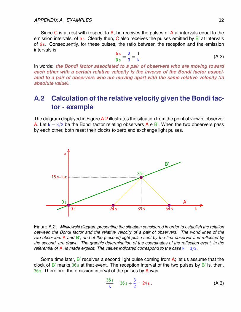
APPENDIX A. EXAMPLES 32
Since C is at rest with respect to A, he receives the pulses of A at intervals equal to theemission intervals, of 6 s. Clearly then, C also receives the pulses emitted by B’ at intervalsof 6 s. Consequently, for these pulses, the ratio between the reception and the emissionintervals is
6 s
9 s=
2
3=
1
k. (A.2)
In words: the Bondi factor associated to a pair of observers who are moving towardeach other with a certain relative velocity is the inverse of the Bondi factor associ-ated to a pair of observers who are moving apart with the same relative velocity (inabsolute value).
A.2 Calculation of the relative velocity given the Bondi fac-tor - example
The diagram displayed in Figure A.2 illustrates the situation from the point of view of observerA. Let k = 3/2 be the Bondi factor relating observers A e B’. When the two observers passby each other, both reset their clocks to zero and exchange light pulses.
..........
..........
..........
..........
..........
..........
..........
..........
..........
..........
..........
..........
..........
..........
..........
..........
..........
..........
..........
..........
..........
..........
..........
..........
..........
..........
..........
..........
..........
..........
..........
..........
..........
..........
..........
..........
..........
..........
..........
..........
..........
..........
........................
.................x
..................................................................................................................................................................................................................................................................................................................................................................................................................................................................................................................................................................................................................................................................................................................................................................................................................................................................................................................................................................................................................................................... .................At
15 s−luz
39 s........................................................................................................
........................................................................................................
........................................................................................................
........................................................................................................
........................................................................................................
........................................................................................................
........................................................................................................
........................................................................................................
.......B’
............................
............................
............................
............................
............................
............................
............................
............................
................................................................................................................................................................................................................................................................................................................... ...........................
...........................
...........................0 s 24 s 54 s
0 s
36 s
.......
.....
.......
.....
.......
.....
.......
.....
.......
.....
.......
.....
.......
.....
.......
.....
..........................................................................................................................................................................................................................................................................
Figure A.2: Minkowski diagram presenting the situation considered in order to establish the relationbetween the Bondi factor and the relative velocity of a pair of observers. The world lines of thetwo observers A and B’, and of the (second) light pulse sent by the first observer and reflected bythe second, are drawn. The graphic determination of the coordinates of the reflection event, in thereferential of A, is made explicit. The values indicated correspond to the case k = 3/2.
Some time later, B’ receives a second light pulse coming from A; let us assume that theclock of B’ marks 36 s at that event. The reception interval of the two pulses by B’ is, then,36 s. Therefore, the emission interval of the pulses by A was
36 s
k= 36 s÷ 3
2= 24 s . (A.3)

APPENDIX A. EXAMPLES 33
Since the first pulse was sent by A when his clock read 0 s, the second pulse was emittedwhen the clock of A indicated 24 s.
Observer B’ sends the pulse back to A. The emission interval between the two pulsessent to A by B’ is 36 s, by the clock of B’. The reception interval of these pulses by A is,therefore,
36 s× k = 36 s× 3
2= 54 s . (A.4)
Since the first pulse was received by A at the instant 0 s, the clock of A reads 54 s when hereceives the reflected pulse, which is the second pulse coming from B’.
For A, the reflection event of the second pulse occurred at the middle instant betweenthe emission and reception instants, that is, when the clock of A marked
24 s + 54 s
2= 39 s . (A.5)
Consequently, for A, the second light pulse he sent took
39 s− 24 s = 15 s (A.6)
to reach the event of reflection by B’. Hence, this event happened at a distance of 15 light−s.Since B’ was present at the reflection event (he provoked it!), A may conclude from thisanalysis that B’ covered 15 light−s in 39 s. The velocity of B’ with respect to A is then
v =15 light−s
39 s=
5
13c . (A.7)
The reader may verify that the relation between k and v, in this example, corresponds to thegeneral formula [see relation (4.10)]
k =
√c + v
c− v, (A.8)
that is, he may check that √1 + 5/13
1− 5/13=
3
2. (A.9)
A.3 Time Dilation - example
In order to illustrate this effect, one may consider the situation presented in section A.2 andvisualized in Figure A.2, taking advantage of much of the associated analysis. The Bondifactor relating observers A and B’ is k = 3/2.
When the two observers pass by each other, both set their clock to zero; therefore, atthis event, the clock of A marks the time 0 s and the clock of B’ also marks 0 s.
However, according to the argument developed in section A.2, when the mirror carried byB’ reflects the second pulse sent by A, the clock of B’ displays the time 36 s but the clock of Aalready indicates 39 s. Hence, for A, the moving clock carried by B’ is running slow. The
APPENDIX A. EXAMPLES 34
ratio between the time intervals measured by the clock at rest and by the clock in motion,known as Lorentz γ factor is
γ =39 s
36 s=
13
12. (A.10)
As demonstrated in the previous section, in this example, the velocity of observer B’ withrespect to observer A is v = 5/13× c. The relationship between the Lorentz factor γ and therelative velocity v, deduced in Chapter 5, is
γ =1√
1− v2/c2. (A.11)
The reader may easily verify that this relation is satisfied in the present example, merely bychecking that
1√1− (5/13)2
=13
12. (A.12)
A.4 Length contraction - example
As explained in chapter 6, one considers a platform whose proper (that is, at rest) length isgiven and one asks what length will be attributed to this same platform by an observer forwhom it is moving with a given velocity.
In this numerical example, it will be assumed that the proper length of the platform is1
L0 = 26 s−luz (A.13)
and that the platform moves with velocity
v =5
13c (A.14)
which, as calculated in Sections A.2 and A.3, corresponds to the Bondi factor
k =3
2(A.15)
and to the Lorentz factorγ =
13
12. (A.16)
Denote by A the observer who performs the measurement of the length of the movingplatform. The procedure utilized by A consists in sending light pulses to be reflected simul-taneously (from his point of view) by mirrors carried by observers B’ and C’ who are locatedeach at one extremity of the platform and are standing still on it.
The diagram of Figure A.3 depicts the situation from the point of view of observer A.Observer B’ passes by observer A first; some time later, observer C’ passes by observer A
1This is quite a respectable length for a platform, about 20 times the distance from the Earth to the Moon!
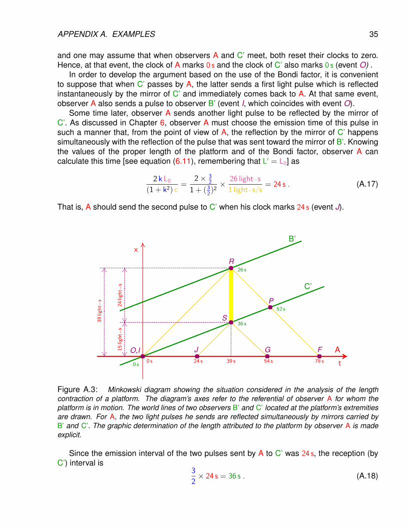
APPENDIX A. EXAMPLES 35
and one may assume that when observers A and C’ meet, both reset their clocks to zero.Hence, at that event, the clock of A marks 0 s and the clock of C’ also marks 0 s (event O) .
In order to develop the argument based on the use of the Bondi factor, it is convenientto suppose that when C’ passes by A, the latter sends a first light pulse which is reflectedinstantaneously by the mirror of C’ and immediately comes back to A. At that same event,observer A also sends a pulse to observer B’ (event I, which coincides with event O).
Some time later, observer A sends another light pulse to be reflected by the mirror ofC’. As discussed in Chapter 6, observer A must choose the emission time of this pulse insuch a manner that, from the point of view of A, the reflection by the mirror of C’ happenssimultaneously with the reflection of the pulse that was sent toward the mirror of B’. Knowingthe values of the proper length of the platform and of the Bondi factor, observer A cancalculate this time [see equation (6.11), remembering that L′ = L0] as
2 k L0
(1 + k2) c=
2× 32
1 + (32)2× 26 light−s
1 light−s/s= 24 s . (A.17)
That is, A should send the second pulse to C’ when his clock marks 24 s (event J).
..........
..........
..........
..........
..........
..........
..........
..........
..........
..........
..........
..........
..........
..........
..........
..........
..........
..........
..........
..........
..........
..........
..........
..........
..........
..........
..........
..........
..........
..........
..........
..........
..........
..........
..........
..........
..........
..........
..........
..........
..........
..........
..........
..........
..........
..........
..........
..........
..........
..........
..........
....................
.................x
............................................................................................................................................................................................................................................................................................................................................................................................................................................................................................................................................................................................................................................................................................................................................................................................................................................................................................................................................................................................ .................A
t........................................................................................................
........................................................................................................
........................................................................................................
........................................................................................................
........................................................................................................
........................................................................................................
........................................................................................................
................................................................................................
........................................................................................................
........................................................................................................
........................................................................................................
........................................................................................................
........................................................................................................
........................................................................................................
........................................................................................................
....B’
C’
............................
............................
............................
............................
............................
............................
............................
............................
............................
............................
............................
............................
............................
............................
............................
............................
............................................................................................................................................................................................................................................................................................................................................................................................................................................................................................................................
............................
............................
............................
............................
............................
..............................................................................................................................................................................................................................................
......................
............................................
......................
......................
......................
O,I
R
FJ
S
G
P
........................................................................................................................................................................................................................................................................................
............................................................................................................................................................................................................................................
...............................................................................................
.......
.....
.......
.....
.......
.....
.......
............
...........
.......
.....
.......
.....
.......
.....
...............
...........
.........................................................
.......................................................................................................................
.......
.....
.......
.....
.......
.....
.......
.....
.......
.....
.......
.....
.......
.....
.......
............
...........
.........................................................................0 s
0 s24 s 54 s39 s 78 s
36 s
52 s
26 s
15light−
s24light−
s
39light−
s
Figure A.3: Minkowski diagram showing the situation considered in the analysis of the lengthcontraction of a platform. The diagram’s axes refer to the referential of observer A for whom theplatform is in motion. The world lines of two observers B’ and C’ located at the platform’s extremitiesare drawn. For A, the two light pulses he sends are reflected simultaneously by mirrors carried byB’ and C’. The graphic determination of the length attributed to the platform by observer A is madeexplicit.
Since the emission interval of the two pulses sent by A to C’ was 24 s, the reception (byC’) interval is
3
2× 24 s = 36 s . (A.18)
APPENDIX A. EXAMPLES 36
Therefore, when C’ receives the second pulse coming from A, his clock marks 36 s (eventS). Since the reflection interval of the two pulses by the mirror of C’ was 36 s, the interval ofreception by A of the reflected pulses must be
3
2× 36 s = 54 s . (A.19)
The time indicated by the clock A when he receives the second pulse reflected by C’ is then54 s (event G).
By the constancy of light velocity, the time attributed by A to the event of reflection, byC’, of the second pulse (event S) must be the median between the time of emission and thetime of reception of the reflected pulse, that is,
24 s + 54 s
2= 39 s . (A.20)
Since, during this time interval, observer C’ moved away from A with velocity 513
c, it is easilydeduced that the reflection event S occurred at a distance from A given by:
5
13× 1 light−s
s× 39 s = 15 light−s . (A.21)
Consider now the light pulse sent by A toward the mirror of B’. It was sent when C’passed by A and reset his clock to zero, therefore at 0 s, by the clocks of B’ and C’. For theseobservers, it took
L0
c=
26 light−s1 light−s
s
= 26 s (A.22)
to reach B’; hence, when his mirror reflects this pulse, the clock of B’ marks 26 s (event R).The reflected pulse takes the same time to get back to C’ and, therefore, when it passes byC’, the clock of C’ marks 52 s (event P). By considering, together with this reflected pulse, theone which was reflected instantaneously when C’ passed by A, one sees that the intervalbetween the passings by C’ of these two pulses was 52 s, by the clock of C’. So, the intervalof reception by A was
3
2× 52 s = 78 s (A.23)
and, when observer A receives the pulse reflected by B’, his clock marks 78 s (event F). Forobserver A, the event of reflection of the pulse by B’ occurred at the median instant betweenthe instant of emission and the instant of reception of the reflected pulse, hence at time
0 s + 78 s
2= 39 s . (A.24)
This confirms then that the reflection events at the two extremities of the platform (eventsR and S) occurred simultaneously for observer A, as had to be the case if the whole operationwas truly to correspond to a measurement, by A, of the platform’s length. To complete thecalculation of this length, it merely remains to determine the distance between observer Aand the most distant extremity of the platform at the time of measurement. Since the lightpulse reflected by B’ took 39 s to reach B’, this distance obviously is
1 light−s
s× 39 s = 39 light−s . (A.25)
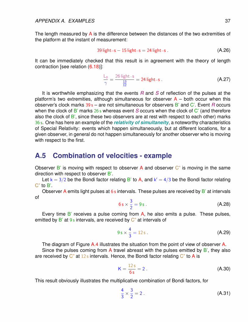
APPENDIX A. EXAMPLES 37
The length measured by A is the difference between the distances of the two extremities ofthe platform at the instant of measurement:
39 light−s− 15 light−s = 24 light−s . (A.26)
It can be immediately checked that this result is in agreement with the theory of lengthcontraction [see relation (6.18)]:
L0
γ=
26 light−s1312
= 24 light−s . (A.27)
It is worthwhile emphasizing that the events R and S of reflection of the pulses at theplatform’s two extremities, although simultaneous for observer A – both occur when thisobserver’s clock marks 39 s – are not simultaneous for observers B’ and C’. Event R occurswhen the clock of B’ marks 26 s whereas event S occurs when the clock of C’ (and thereforealso the clock of B’, since these two observers are at rest with respect to each other) marks36 s. One has here an example of the relativity of simultaneity, a noteworthy characteristicsof Special Relativity: events which happen simultaneously, but at different locations, for agiven observer, in general do not happen simultaneously for another observer who is movingwith respect to the first.
A.5 Combination of velocities - example
Observer B’ is moving with respect to observer A and observer C” is moving in the samedirection with respect to observer B’.
Let k = 3/2 be the Bondi factor relating B’ to A, and k′ = 4/3 be the Bondi factor relatingC” to B’.
Observer A emits light pulses at 6 s intervals. These pulses are received by B’ at intervalsof
6 s× 3
2= 9 s . (A.28)
Every time B’ receives a pulse coming from A, he also emits a pulse. These pulses,emitted by B’ at 9 s intervals, are received by C” at intervals of
9 s× 4
3= 12 s . (A.29)
The diagram of Figure A.4 illustrates the situation from the point of view of observer A.Since the pulses coming from A travel abreast with the pulses emitted by B’, they also
are received by C” at 12 s intervals. Hence, the Bondi factor relating C” to A is
K =12 s
6 s= 2 . (A.30)
This result obviously illustrates the multiplicative combination of Bondi factors, for
4
3× 3
2= 2 . (A.31)
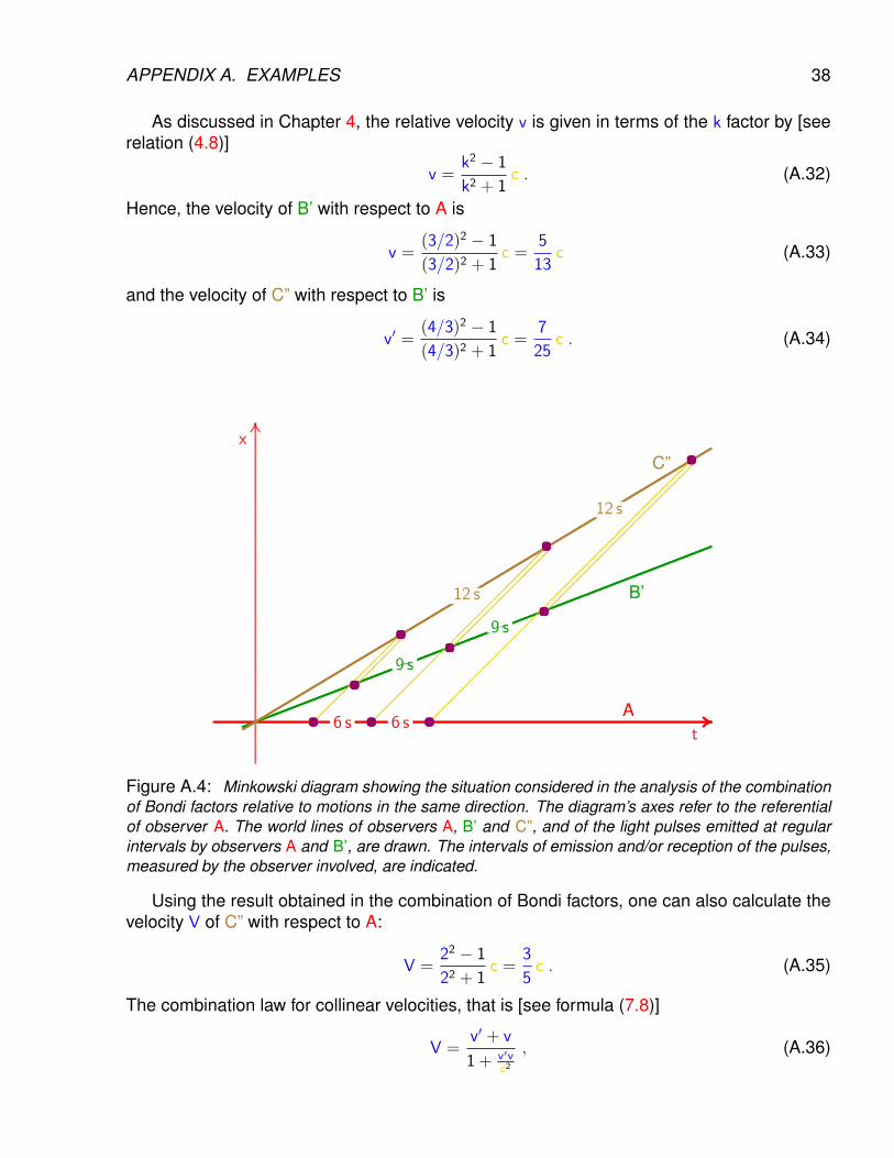
APPENDIX A. EXAMPLES 38
As discussed in Chapter 4, the relative velocity v is given in terms of the k factor by [seerelation (4.8)]
v =k2 − 1
k2 + 1c . (A.32)
Hence, the velocity of B’ with respect to A is
v =(3/2)2 − 1
(3/2)2 + 1c =
5
13c (A.33)
and the velocity of C” with respect to B’ is
v′ =(4/3)2 − 1
(4/3)2 + 1c =
7
25c . (A.34)
..........
..........
..........
..........
..........
..........
..........
..........
..........
..........
..........
..........
..........
..........
..........
..........
..........
..........
..........
..........
..........
..........
..........
..........
..........
..........
..........
..........
..........
..........
..........
..........
..........
..........
..........
..........
..........
..........
..........
..........
..........
..........
..........
..........
..........
..........
..........
..........
..........
..........
..........
..........
..........
..........
..........
..........
..........
..........
.....................
.................x
....................................................................................................................................................................................................................................................................................................................................................................................................................................................................................................................................................................................................................................................................................................................................................................................................................................................................................................... .................At
........................................................................................................
........................................................................................................
........................................................................................................
........................................................................................................
........................................................................................................
........................................................................................................
........................................................................................................
........................................................................................................
..............................
B’
..........................................................................
..........................................................................
..........................................................................
..........................................................................
..........................................................................
..........................................................................
..........................................................................
..........................................................................
..........................................................................
..........................................................................
..........................................................................
..........................................................................
..................................................
C”
............................
............................
............................
............................
............................
............................
............................
................
............................
............................
............................
............................
............................
............................
............................
............................
............................
............................
............................
............................
............................
............................
............................
...
............................
............................
............................
............................
............................
............................
............................
............................
............................
............................
............................
............................
............................
............................
............................
............................
............................
............................
............................
............................
............................
............................
..................
..........................
..........................
..........................
..........................
.....................
............................
............................
............................
............................
............................
............................
............................
............................
.......................
............................
............................
............................
............................
............................
............................
............................
............................
............................
............................
............................
............................
............................
......
....................... ....................... ..............................................
.....................................................................
.......................
.......................
6 s 6 s
9 s
9 s
12 s
12 s
Figure A.4: Minkowski diagram showing the situation considered in the analysis of the combinationof Bondi factors relative to motions in the same direction. The diagram’s axes refer to the referentialof observer A. The world lines of observers A, B’ and C”, and of the light pulses emitted at regularintervals by observers A and B’, are drawn. The intervals of emission and/or reception of the pulses,measured by the observer involved, are indicated.
Using the result obtained in the combination of Bondi factors, one can also calculate thevelocity V of C” with respect to A:
V =22 − 1
22 + 1c =
3
5c . (A.35)
The combination law for collinear velocities, that is [see formula (7.8)]
V =v′ + v
1 + v′vc2
, (A.36)
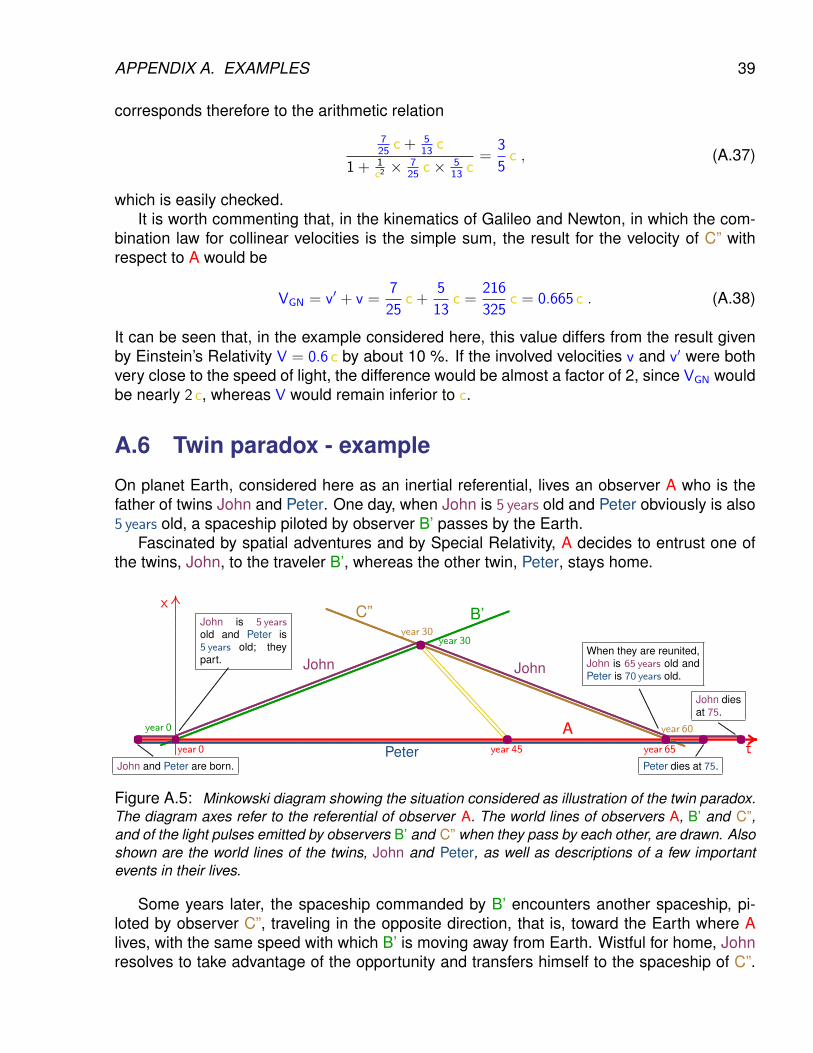
APPENDIX A. EXAMPLES 39
corresponds therefore to the arithmetic relation
725
c + 513
c
1 + 1c2× 7
25c× 5
13c=
3
5c , (A.37)
which is easily checked.It is worth commenting that, in the kinematics of Galileo and Newton, in which the com-
bination law for collinear velocities is the simple sum, the result for the velocity of C” withrespect to A would be
VGN = v′ + v =7
25c +
5
13c =
216
325c = 0.665 c . (A.38)
It can be seen that, in the example considered here, this value differs from the result givenby Einstein’s Relativity V = 0.6 c by about 10 %. If the involved velocities v and v′ were bothvery close to the speed of light, the difference would be almost a factor of 2, since VGN wouldbe nearly 2 c, whereas V would remain inferior to c.
A.6 Twin paradox - example
On planet Earth, considered here as an inertial referential, lives an observer A who is thefather of twins John and Peter. One day, when John is 5 years old and Peter obviously is also5 years old, a spaceship piloted by observer B’ passes by the Earth.
Fascinated by spatial adventures and by Special Relativity, A decides to entrust one ofthe twins, John, to the traveler B’, whereas the other twin, Peter, stays home.
..........
..........
..........
..........
..........
..........
..........
..........
..........
..........
..........
..........
..........
..........
..........
..........
..........
..........
..........
..........
..........
..........
..........
..........
..........
..........
..........
..........
..........
..........................
.................x
................................................................................................................................................................................................................................................................................................................................................................................................................................................................................................................................................................................................................................................................................................................................................................................................................................................................................................................................................................................................................................................................................................................................................................................................................................ .................At....................................................
........................................................................................................
........................................................................................................
........................................................................................................
........................................................................................................
........................................................................................................
........................................................................................................
............................B’....................................................................................................................................................................................................................................................................................................................................................................................................................................................................................................................................................................................................................................................................................................................................................
C”
...........................................................................................................................................................................................................................................................................................................................................................................................................................................................................................................................................................................................................................................................................................................................................................................................................................................................................................................................................................................................................................................................................................................Peter
........................................................................ ........................................................................................................
........................................................................................................
........................................................................................................
........................................................................................................
...............................................................................................................................................................................................................................................................................................................................................................................................................................................................................................................................................................................................................................................................................................................................................
John John
..................................................................................................................................................................................................................................................
....................................................................................................................................................................................................................................................................
.......................
....................... .............................................. ....................... .......................year 0
year 0
year 30year 30
year 45 year 65
year 60
John is 5 yearsold and Peter is5 years old; theypart.
When they are reunited,John is 65 years old andPeter is 70 years old.
John and Peter are born. Peter dies at 75.
John diesat 75.
......................................................................................................................................................
......................
......................
......................
.................
..............................................................
..................................
....
Figure A.5: Minkowski diagram showing the situation considered as illustration of the twin paradox.The diagram axes refer to the referential of observer A. The world lines of observers A, B’ and C”,and of the light pulses emitted by observers B’ and C” when they pass by each other, are drawn. Alsoshown are the world lines of the twins, John and Peter, as well as descriptions of a few importantevents in their lives.
Some years later, the spaceship commanded by B’ encounters another spaceship, pi-loted by observer C”, traveling in the opposite direction, that is, toward the Earth where Alives, with the same speed with which B’ is moving away from Earth. Wistful for home, Johnresolves to take advantage of the opportunity and transfers himself to the spaceship of C”.
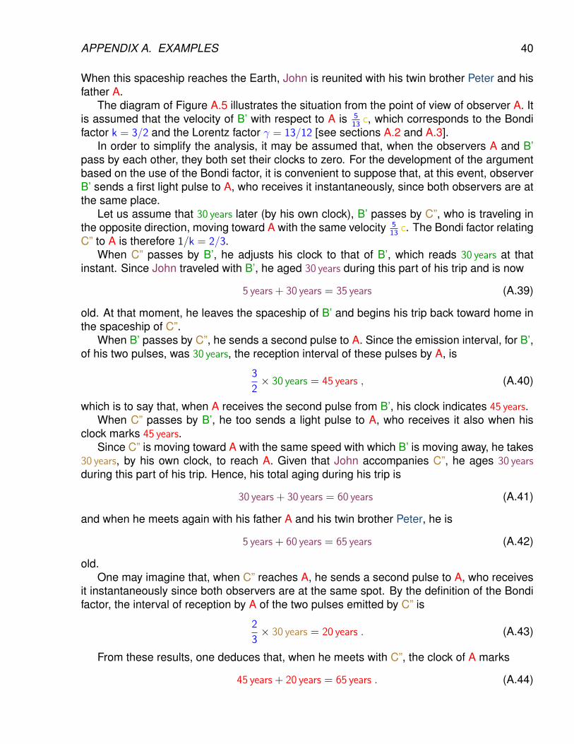
APPENDIX A. EXAMPLES 40
When this spaceship reaches the Earth, John is reunited with his twin brother Peter and hisfather A.
The diagram of Figure A.5 illustrates the situation from the point of view of observer A. Itis assumed that the velocity of B’ with respect to A is 5
13c, which corresponds to the Bondi
factor k = 3/2 and the Lorentz factor γ = 13/12 [see sections A.2 and A.3].In order to simplify the analysis, it may be assumed that, when the observers A and B’
pass by each other, they both set their clocks to zero. For the development of the argumentbased on the use of the Bondi factor, it is convenient to suppose that, at this event, observerB’ sends a first light pulse to A, who receives it instantaneously, since both observers are atthe same place.
Let us assume that 30 years later (by his own clock), B’ passes by C”, who is traveling inthe opposite direction, moving toward A with the same velocity 5
13c. The Bondi factor relating
C” to A is therefore 1/k = 2/3.When C” passes by B’, he adjusts his clock to that of B’, which reads 30 years at that
instant. Since John traveled with B’, he aged 30 years during this part of his trip and is now
5 years + 30 years = 35 years (A.39)
old. At that moment, he leaves the spaceship of B’ and begins his trip back toward home inthe spaceship of C”.
When B’ passes by C”, he sends a second pulse to A. Since the emission interval, for B’,of his two pulses, was 30 years, the reception interval of these pulses by A, is
3
2× 30 years = 45 years , (A.40)
which is to say that, when A receives the second pulse from B’, his clock indicates 45 years.When C” passes by B’, he too sends a light pulse to A, who receives it also when his
clock marks 45 years.Since C” is moving toward A with the same speed with which B’ is moving away, he takes
30 years, by his own clock, to reach A. Given that John accompanies C”, he ages 30 yearsduring this part of his trip. Hence, his total aging during his trip is
30 years + 30 years = 60 years (A.41)
and when he meets again with his father A and his twin brother Peter, he is
5 years + 60 years = 65 years (A.42)
old.One may imagine that, when C” reaches A, he sends a second pulse to A, who receives
it instantaneously since both observers are at the same spot. By the definition of the Bondifactor, the interval of reception by A of the two pulses emitted by C” is
2
3× 30 years = 20 years . (A.43)
From these results, one deduces that, when he meets with C”, the clock of A marks
45 years + 20 years = 65 years . (A.44)
APPENDIX A. EXAMPLES 41
Since Peter remained together with A the whole time, he aged 65 years and is therefore
5 years + 65 years = 70 years (A.45)
old when he meets C”, an event that corresponds also to his re-encounter with his twinbrother John.
One concludes that, when the twins are finally reunited, John is 65 years old and Peter is70 years old. That is to say: the twin who went away and came back aged more slowlythan the other, who stayed home.
It is easy to check that the ratio between the aging of John, who traveled, and the aging ofPeter, who stayed put, is given by the inverse of the Lorentz factor, as formula (8.8) predicts:
60 years
65 years=
12
13=
1
γ. (A.46)
Given that the twins are biologically identical, it is plausible that both die when they reachthe same biological age, 75 years, for example. However, when Peter passes away, at age 75,John will be only 70 years old and he will spend the last 5 years of his life mourning the loss ofhis brother Peter.
Bibliography
[] Hermann Bondi, Relativity and Common Sense: a new Approach to Einstein, DoverPublications Inc, New York, USA, 1980.
42


![[Jeffie Betz] Playing Piano](https://static.documents.pub/doc/80x56/577cd07b1a28ab9e78925f4b/jeffie-betz-playing-piano.jpg)


