AutoCAD MEP (AMEP) is an object-based Computer Aided Design (CAD) software pack-age. It differs from the AutoCAD foundation upon which it is built in a number of ways.The major difference is in its focus on modeling over drafting. The main goal of the soft-ware is to facilitate the creation of a virtual building model from which plans, sections,elevations as well as quantities and other data can be readily extracted. The extracteddrawings serve as two-dimensional “reports” of the “live” 3D model data. The advantagesof this approach are many. From a 2D production point of view, this means less timedrafting and coordinating building data because plans and sections are both being gener-ated from the same source data. If the data changes, both plan and section receive thechange. Schedules and data reports of quantities, component sizes, materials used, andscores of other property data are also within the realm of possibility and fully accessible.To achieve this level of functionality, it is important to understand a bit about whatmakes AMEP tick. That is the goal of this chapter. In particular, the focus will be on threemajor AMEP concepts that are not available in the underlying AutoCAD drafting package.These are: display control, anchors, and object styles. Drawing Management and PropertySets also offer power and flexibility not available within standard AutoCAD; but thesetopics will be covered extensively in Chapters 3 and 14, respectively.
OBJECTIVES
In this chapter, we will explore the meanings of parametric design, Building InformationModeling (BIM) and object-oriented CAD. Following the steps of a tutorial on the displaysystem, you will learn how to display a single drawing model in many different wayswhich serve a variety of drawing and documentation needs. By exploring the Style Man-ager, we will begin to gain comfort with some of the critical conceptual underpinnings ofthe AMEP software package. Upon completion of this chapter you will be able to:
• Understand objects and their properties.
• Work with the display system.
• Understand object styles.
• Locate and quickly import content from a vast library of provided items.
PARAMETRIC DESIGNObjects in AMEP are programmed to represent the real-life objects for which theyare named. All real-life objects have a series of defining characteristics that determinetheir shape, size, and behavior. Parametric Design allows us to design while manipu-lating those real-world parameters directly on the objects.
To get a better sense of what these parameters might be, think of the characteristic towhich you would refer if describing the object verbally to a colleague without the ben-efit of a drawing. Consider, for instance, a duct. If discussing a particular duct neededin a project with the contractor over the telephone, we would rely on descriptive ad-jectives and verbal dimensions such as “the duct is rectangular, has a particular widthand a particular height, and it has insulation.” Once we had settled on the duct re-quired and hung up the phone, we would then need to convey graphically in ourdrawing documents the decisions we had just made regarding that duct (and anyothers like it). In traditional 2D Design, this would mean translating dimensionsand materials into corresponding lines, arcs, circles and/or blocks that represent therequired dimensions and materials in the drawing. In AMEP, dimensions and otherspecifications are simply input into a series of fields and stored with the data for theobject. This data remains accessible throughout the life of the object and the drawingvia the object’s properties. Therefore, the next time we phone the contractor and real-ize that circumstances on the site have forced us to specify a different duct size, ratherthan redraw the duct and manually adjust the adjacent fittings as we would in tradi-tional 2D Design, we now simply re-access the properties for that duct and input thenew values. Not only does the duct itself update because of this change, but the adja-cent fittings connected to the duct update as well. Other linked views such as Eleva-tions and Schedules will also receive the change. This is just one example ofparametric design. Object parameters are always available for editing; data neverneeds to be recreated, only manipulated. Some principles of parametric design are asfollows:
• Draw Once—In traditional 2D Design, each object needs to be drawn for eachrequired view; therefore the same duct or lighting fixture may need to be drawntwo, three or more times. With AMEP, objects need only be drawn once. Theyare then “represented” in each of the required views of Plan, Section andElevation.
• Progressive Refinement—Complete or final design information is rarely knownat the early stages of a design project. Changes occur frequently and often sev-eral times. In traditional 2D Design, it is easy to add new information. However,when major design changes occur, drawings must often undergo time-consuming redrafting. With AMEP, designs can be progressively refined overthe life of the project. As new data is learned or design changes occur, objectparameters may be adjusted appropriately without the need to erase and recre-ate the drawing. The objects are drawn once, and then modified and refined asrequired.
• Style-Based versus Object-Based—Most AMEP objects make use of styles. Astyle is a collection of object parameters saved in a named group. When stylesare assigned to objects, all properties of the style are transferred to the objectin one step. If the style parameters change later, all of the objects using thestyle will change as well. This is similar to the behavior exhibited by text anddimension styles in traditional AutoCAD. AMEP simply utilizes many morestyles, and manages them and their relationships to objects much morecompletely than the corresponding AutoCAD counterparts. In some cases how-ever, object parameters are assigned directly to the individual objects and not
Chap t e r 2 • Con c e p t u a l Und e r p i nn in g s o f Au t oCAD MEP 91
controlled by the style. Consider again the duct object as an example. The DuctSystem style would be used to designate the duct design parameters, such asthe surface roughness, and air density. However, ducts can come in a varietyof sizes; the roughness is a style-based parameter, while the size is an object-based parameter.
• Live versus Linked—Some drawing types in AMEP are edited directly on the“live” model data. This is the case with floor plans or live sections. The displaysystem, discussed later in this Chapter, controls what displays on the screen aswe are working in AMEP. Plan views are live. If changes are made to the objectswithin the plan, those changes will be seen simultaneously on the live model inall other live views. However, some drawing types, namely 2D sections, 2D ele-vations, and schedules, are “linked.” Rather than being a live view of the model,these separate drawings function as “reports” of the model that maintain a linkto the live model data. These views must be periodically refreshed to capturechanges made to the model. Luckily, there are tools and settings to automatethese tasks.
What is AMEP? Simply stated, AMEP is the version of AutoCAD you should beusing if you are tasked with the creation of construction documents for the Mechani-cal, Electrical, and Plumbing (MEP) disciplines in a building project. AMEP embo-dies decades of AutoCAD related drafting standard capabilities, providesfunctionality specifically suited to MEP documentation, and provides flexibility forthe editing drawing elements more quickly and easily than manual drafting techni-ques. In addition to expediting 2D drafting tasks, AMEP elements are also 3D ob-jects which make them suitable for interference detection, quantification, andvisualization that is not possible in traditional 2D workflows (see Table 2.1).
TABLE 2.1 Types of Content in AutoCAD, AutoCAD Architecture, and AutoCAD MEP
AutoCAD AutoCAD Architecture AutoCAD MEP
TemplatesDimension StylesText StylesLayer SettingsPalettesPalette ToolsBlocks,Blocks and moreBlocks
Door StylesWall StylesCurtain Wall StylesWindow StylesSlab StylesStair StylesStructural Member StylesWall Cleanup StylesSpace StylesZone StylesProperty Set DefinitionsProperty Data FormatsSchedulesMulti-View Blocks(Equipment and furnishings)Multi-View Blocks (Tags)
DuctsDuct FittingsFlex DuctDuct System StylesPipesPipe FittingsFlex PipesPipe System StylesConduitConduit FittingsCable TrayCable Tray FittingsElectrical System StylesMulti-View Parts (MvParts)Wire StylesDevice StylesPanel StylesLabel Styles and more…
92 The Aub in A c ad emy Ma s t e r S e r i e s : Au t oCAD MEP 2011
AutoCAD provides the familiar user interface, command line, plotting capabilities,snaps and general foundation for AMEP. Everything that you have and are used tousing in AutoCAD is in AMEP. AMEP is built on top of AutoCAD Architecture,which provides the Object Modeling Framework (OMF) – this is a fancy way of say-ing that in AMEP, you are modeling objects that represent their real world counter-parts (Ducts, Electrical Panels, etc.). The components you interact with in AMEPhave specific common functionality, namely how their display is controlled. In addi-tion to the familiar layering functionality of AutoCAD, the OMF provides the abilityto define multiple representations of an object, and the DisplayManager provides theability to display a particular representation of that object depending on the configu-ration of the display. For example, in a 3D view, an Electrical Device such as a recep-tacle may be represented to look like a junction box with a faceplate, whereas in Planit will be the familiar symbol comprised of a circle with two lines. Similarly, in a 3Dview, a Duct will appear as an extruded solid, whereas in Plan all AMEP needs todraw are the edges of the duct as lines.
There are some fundamental differences between AutoCAD and AMEP objects.The most fundamental is that AMEP provides a Display System that allows MEP(and Architectural) objects to be represented differently under various viewing condi-tions. The most common conditions are 2D, 3D and Section views. Additionally,AMEP objects utilize automatic layering based on industry or office standards. Fur-thermore, a large catalog of pre-built content with components featuring specializedbehaviors is also included. All of these items contribute to what is perhaps the biggestdifference between traditional AutoCAD and AMEP; using AMEP effectivelyrequires a change in work process. When you use AutoCAD, you draft individualdrawings from individual lines, arcs and circles. There is nothing about two parallellines drawn in the shape of a duct run that makes them behave like a duct or somehowimparts duct-like awareness upon them. In other words, AutoCAD cannot distin-guish between two lines representing a duct from two lines representing a wall totwo lines representing a parking space. All are drawn similarly, and to AutoCAD,they are just two lines on a layer.
In AMEP, you do not draft a duct, but rather you “model” a duct. By selecting anappropriate duct, and specifying the characteristics of the run, you build a representa-tion (or model) simulating what will ultimately be built. In this approach you canwork in a traditional 2D view or even work three-dimensionally if preferred. Thereare many advantages to this approach. In the act of laying out your ductwork, youchoose type, size, and other characteristics. As you draw the run, it automatically ap-pears on an appropriate layer. Further, you are able to view the resultant model in planto see a traditional two-dimensional (i.e., two lines) representation of the duct andalso view it three-dimensionally. Such three-dimensional views can be used to assistin understanding the design, making design decisions, and identifying clashes usingthe Interference Detection tool (Analyze ribbon, Inquiry panel). Since a duct or pipeor fixture object simulates the real-world object it is meant to represent, we are able totake advantage of not only the many characteristics of the object itself but also therelationships of elements to one another in the systems as a whole. TraditionalAutoCAD offers none of these benefits. Its only strength by comparison is its famil-iarity and emulation of traditional workflows and procedures. However, once youhave immersed yourself in the lessons of this book, you will find yourself as familiarwith the AMEP workflow as you previously were at AutoCAD.
Chap t e r 2 • Con c e p t u a l Und e r p i nn in g s o f Au t oCAD MEP 93
To begin a more thorough understanding of the whole of AMEP, the main drawingcomponents available in the software for design modeling and documentation arelisted in the following table.
TABLE 2.2 Types of Objects in AutoCAD MEP
Object Type PurposeKey Differentiator fromAutoCAD
Duct Used to represent duct. Avail-able in Rectangular, Round,and Flat Oval
3D components that automaticallyadjust interconnected componentswhen grip editing.
Pipe Used to represent pipe. 3D components that automaticallyadjust interconnected componentswhen grip editing.
Plumbing Line 2D linework to representplumbing systems.
Typical fittings insert automati-cally, and interconnected compo-nents adjust automatically whenediting.
Conduit Used to represent conduitwireways.
3D components that automaticallyadjust interconnected componentswhen editing.
Cable Tray Used to represent cable traywireways.
3D components that automaticallyadjust interconnected componentswhen editing.
Hanger Used to represent structuralelements for supporting duct,pipe, conduit, and cable traysystems.
3D components that can be laidout along a run of routedcomponents.
Device Used to represent buildingelements such as receptacles,lighting fixtures, switches,security devices, fire alarmdevices, and communicationsdevices.
Devices provide the ability todefine power requirements, andmay be circuited to panels.
Panel Used to represent electricaldistribution components thatprovide an origination pointfor circuits.
Provides a mechanism to circuitdevices to panels to maintainelectrical connectivity and com-puted load information.
Wire Used to annotate schematicwiring between devices.
Tick marks are an embedded partof the wire, and wires may be usedto facilitate the circuiting process.Automatically “break” whencrossing other wires. (Note: Wiresare not required for circuiting.)
MvParts Used to represent generalcomponents.
Components with 2D and 3Drepresentations.
94 The Aub in A c ad emy Ma s t e r S e r i e s : Au t oCAD MEP 2011
THE DISPLAY SYSTEMEarly in our design careers, we learned the traditional rules of drafting. Those rulesgoverned such things as what a plan or elevation drawing represents, how to createone, and more importantly, what to include and what not to include in making thedrawing “read.” Although there are accepted universal rules in place, part of the pro-cess involves personal style. Therefore, the rules need to be consistent enough to allowthem to convey information reliably, and flexible enough to allow for stylistic varia-tion. Amazingly enough, although CAD software such as AutoCAD has revolution-ized the way design drawings are created, prior to AMEP, the software offered nospecialized tools to assist the designer in achieving the unique graphical look requiredby architectural documents. Rather, lines were still painstakingly laid out one at atime as they had been in hand drafting, following the internalized prescriptionslearned on the job. If a plan, section, and elevation were required to convey designintent, three completely separate drawings needed to be created and, more impor-tantly, coordinated. The display system in AMEP addresses this situation by incor-porating the rules of drafting directly into the software. Plans, sections, and elevationscan now be generated directly from a single building model. This reduces rework andredundancy by requiring one set of objects, with three different modes of display (seeFigure 2.1). The tools are flexible and fully customizable, so we can fully benefit fromthis powerful tool and still introduce the nuances of our own personal style into theprocess.
MvBlocks (Tags) Used to annotate any informa-tion about an element (i.e.,elevation, circuit, type, etc.)
Automatically update if theunderlying data changes.
Labels Used to annotate information(typically size) along the lengthof Duct, Pipe, Conduit, andCable Tray
Automatically update if the size orother property changes.
Panel Schedules(AutoCAD Tables)
Used to report connected anddemand load information forPanel.
Data is extracted directly from theconnected components, and maybe updated without manuallyentering data into the schedule.
Schedules Used to report type and otherinformation about a group ofobjects.
Data is extracted Property SetData in Property Set Definitions,and is reported in the schedule.
Schematic Symbol 2D schematic diagrammingcomponents.
The best way to quickly understand the display system is to start with the drawing templatefiles (DWT) provided with the software. Much of the display system has already been config-ured for typical design situations in these templates. For most firms, these templates can beused “as-is” or with minor customization. If you are new to AutoCAD MEP, begin with theout-of-the-box templates and display system configurations and then slowly begin customiz-ing them to suit your firm’s particular needs as required. This approach guarantees a com-plete understanding of the tools as you learn by example using suggested settings.The display system is complex, but it is also extremely powerful. In order to fully masterthe use of AMEP, it is important to become very comfortable with the display system.
FIGURE 2.1 Generating plan, section, elevation and schedule views from a single model
96 The Aub in A c ad emy Ma s t e r S e r i e s : Au t oCAD MEP 2011
The Display System’s Relationship to LayersObjects unique to AMEP are referred to as “AEC Objects” (including objects fromAutoCAD Architecture and Civil 3D). They include objects such as Ducts, Devices,Pipes and Schedules. Display control determines how AEC objects are displayedunder different viewing conditions and circumstances. (Display control has no effecton AutoCAD entities such as lines, arcs and circles.) Layers are used as a global orga-nizational tool for the management of drawing data, much like a drawing-wide cate-gorization system. All objects (both AutoCAD and AEC) are placed on a layer whenthey are created. Display control supplements layers in helping you control what isseen and how it is displayed on the screen and in print. Each AEC object contains aseries of components. The display control tools determine the display characteristicsof each of these components. In some cases, the display properties of individual AECobject subcomponents are in fact handled by layers, although this is certainly not re-quired (and in many cases not desired either). To summarize, Layers know nothing ofDisplay; however, Display settings can optionally include Layers. Layers work on allentities, AutoCAD and AEC alike, but Display works only with AEC objects. Bothcan be used to control what is seen on screen and in print. Layers do this globally in anabsolute way—they cannot respond to the condition of the drawing. Display settingscan change if the condition of the drawing meets certain criteria. The Display systemhas been designed specifically with MEP and Architectural drawing needs in mind;Layers have not.
Overview and Key Display System FeaturesThe display system offers many features and benefits:
• AEC objects display differently under various viewing conditions—Displaycontrol settings can dynamically change the display of a building model fromplan to elevation to section or 3D model, with a simple change in the viewingdirection on screen.
• Fully customizable—Configuration of the display system components and theirindividual object properties can be customized to suit specialized needs. Cus-tomization can be as simple as modifying a setting or two in the configurationsprovided in the default templates, or as complex as a completely custom-builtsolution tailored to a project-specific or office-wide need.
• Understands the nuances of MEP and Architectural drafting—Object com-ponents such as Lining (Ducts), Insulation (Ducts and Pipes), provide very spe-cific control over how elements are displayed. Display by Elevation functionalityprovides the further ability to automatically hide or change the linework of ele-ments at different elevations.
The Display System Tool SetThe display system tool set consists of a collection of interconnected components. Itis important to understand some concepts and terminology related to each of thesecomponents before you begin to work with the display system.
• Object/Subcomponents—All AEC objects contain one or more subcompo-nents. These are simply the individual pieces of the object. A duct, for example,contains (among others) the following plan subcomponents: Contour, Insula-tion, Lining, and Center Line. Just like traditionally drafted AutoCAD entities(lines, arcs and circles), the entire object (the Duct in this case) will be assignedAutoCAD properties such as Layer and Lineweight, while the individual
Chap t e r 2 • Con c e p t u a l Und e r p i nn in g s o f Au t oCAD MEP 97
subcomponents may also receive their own individual properties through theirobject display settings.
• Display Properties—Display properties are the collection of display settings fora particular object. These include Visibility mode (On or Off), Layer, Color, Line-type, Lineweight, LTScale, and Plot Style. They also include many object-specificsettings like Rise Drop. These are applied as “Drawing Default,” “System StyleOverride”, “Style Override” or “Object Override” level.
• Drawing Default—In the hierarchy of display settings, the Drawing Default set-tings come first and establish the baseline for a particular type of object: allwalls, all stairs, etc., within a particular drawing.
• System Style Override—System Style Override affects a subset of drawing ob-jects that are assigned to a particular System. Establishing the display settingsat the object’s system level provides a means to distinguish elements that servea particular purpose (such as Chilled Water Piping vs. Condenser Water Pipingor Existing Piping vs. New Piping). System Style-level settings override theDrawing Default settings. Generally, however, the graphical differences are lim-ited to settings on the layer associated with the system.
• Style Override—Style Override affects a subset of drawing objects that belongto the particular style in question only. Style-level settings override the DrawingDefault and, if present, the System Style settings. In general, application ofstyle-level overrides should typically be avoided.
• Object Override—Object Override affects only a single object selected in thedrawing. Object-level settings override those of both the Drawing Default and,if present, the System Style and Style Override. In general, frequent applicationof object-level overrides should typically be avoided.
• Display Representation (Display Rep)—As dictated by the conventional rulesof drafting, each type of object has one or more ways in which it may be drawn.Display representations control the behavior of objects under various drawingsituations such as Plan and Elevation. Representations also control the specificdisplay characteristics of an object’s individual subcomponents from a particularviewpoint (see Figure 2.2).
• Set—Set describes which objects will display in a particular drawing situation,and in which mode—Display Representation—they will be displayed. A Setclosely approximates a particular type of drawing, such as “Floor Plan” or “Build-ing Section” (see Figure 2.2).
• Display Configuration—Configuration controls which Display RepresentationSet will appear on the screen, as determined by a particular viewing direction.Configurations can be “Fixed View” (same set appears regardless of currentview direction) and “View Direction Dependent” (loads a different set basedupon view direction). See Figure 2.2.
Putting It All TogetherSummarizing how all of these components fit together, objects have one or more Dis-play Representations (display modes). These Representations control the On/Offstate, Layer, Color, Linetype, Lineweight, and Plot Style of each of the object’s inter-nal subcomponents. These can be assigned in one of four ways: by Drawing Default,System Style Override, Style Override, or Object Override. Most of these settings areavailable on the Display tab of the Properties palette. Individual objects and theirappropriate Representations are grouped together in a Set. Sets are loaded into theviewport based on the conditions outlined in the Display Configuration. Changingthe viewport view direction will trigger the display of appropriate Sets based on these
98 The Aub in A c ad emy Ma s t e r S e r i e s : Au t oCAD MEP 2011
conditions. Figure 2.2 shows two examples of these relationships (a Device in eleva-tion and in plan) in a flow chart style to illustrate the concept. The far bottom leftshows the Views toolbar. Next to it is the Display Configuration menu on the draw-ing status bar (first shown in Figure 1.3). These two items together trigger the rest ofthe items illustrated. The screen captures in the middle of the figure are from theDisplay Manager, available on the Manage tab, Style and Display panel. The Displaytab of the Properties palette is depicted in two scenarios on the right.
The display system is dynamic. Changes made to its settings are immediately evidentin the drawing. Many aspects of its configuration can be set up once and used fromone drawing to the next, but certain settings will be in a constant state of flux as proj-ect needs dictate. The goal of the display system is to provide a unified tool set forcontrolling the myriad of display needs in architectural and MEP drawings. Thegoal here is twofold: reduce some of the tedium associated with drafting, and createa single building model that is capable of representing itself in all the ways necessaryto display the drawings required in a document set. With the display system, it is nolonger necessary to draw the same data two or three times to accommodate plans,sections, elevations and schedules. Features such as those offered by the displaysystem are central to the concept of Building Information Modeling.
Working with the Display SystemWe begin our exploration of the display system by exploring the settings contained inthe default template files. The display system is configured in much the same way ineach of the out-of-the-box templates. The dataset used here was created from theAecb Model (US Imperial Ctb).dwt template file.
FIGURE 2.2 The relationship of components in the display system
Chap t e r 2 • Con c e p t u a l Und e r p i nn in g s o f Au t oCAD MEP 99
Install the Dataset and Open a FileIf you have not already done so, please install the dataset files from the MasteringAutoCADMEP dataset files from the student companion.
1. Install the dataset files located on the Mastering AutoCAD Architecture 2010dataset files from the student companion.
Refer to “Files Included on the dataset files from the student companion in thePreface for information on installing the sample files included on the datasetfiles from the student companion.
2. Launch AutoCAD MEP 2010.
We are going to load several different Display Configurations. Be sure to Zoom andPan around the drawing a bit after each change to see the complete effect.
3. From the C:\MasterACA 2010\Chapter02 folder, open the file Chapter 02.dwg.
The current Display Configuration is MEP Design. This is the “standard” DisplayConfiguration that may be used for most MEP design work.
Loading a Display Configuration4. On the drawing status bar, on the right side, open the Display Configuration
pop-up menu (it currently reads “MEP Design”).
A menu list of all Display Configurations appears (see Figure 2.3).
5. Choose Mechanical (see Figure 2.4).
Zoom and pan around the drawing to see the change. Notice that all theelectrical objects are screened.
NOTE In the following images, tags hide with their associated objects; however, this won’t happenin your drawing; you will configure this later.
FIGURE 2.3 The Display Configuration pop-up menu on the Drawing status bar
100 The Aub in A c ad emy Ma s t e r S e r i e s : Au t oCAD MEP 2011
Zoom and pan around the drawing to see the change. Notice that power devicesare hidden, and mechanical components (except for Multi-View Parts) arescreened.
7. From the Display Configuration pop-up menu on the drawing status bar, chooseElectrical - Power (see Figure 2.6).
NOTE In each case, you might notice a slight delay while the Display Configuration loads andmakes the change to the drawing.
FIGURE 2.6 Load Electrical-Power from the Display Configurations list
FIGURE 2.7 Load MEP Basic 2-Line from the Display Configurations list
102 The Aub in A c ad emy Ma s t e r S e r i e s : Au t oCAD MEP 2011
Notice the change to the drawing: Lighting Fixtures and Air Terminals are hidden,and Duct and Pipe are screened.
8. From the Display Configuration pop-up menu on the drawing status bar, chooseMEP Basic 2-Line (see Figure 2.7).
In this configuration, the display is very similar to MEP Design where all compo-nents are shown non-screened. However, hidden lines are not computed or drawn,resulting in quicker drawing regeneration time.
As you can see, loading Display Configurations has a broad effect upon the entiredrawing. The goal of a Display Configuration is to adjust the display of all AECobjects within the drawing to suit a particular design or presentation situation. Thosesituations range from floor plans to presentation plans. For most plan drawings, theremay be no need to change the Display Configuration; however, you may periodicallychange the current Display Configuration to help you see things more clearly as youwork. You may also find yourself fine-tuning the Display Configurations to suit yourown particular workflows, and find yourself using layer control less frequently.
9. Reload the MEP Design Display Configuration.
Notice the drawing’s change back to the default Display Configuration.
By loading these Configurations you can begin to see some of the power of the displaysystem; particularly when it comes to displaying the same information in varyinggraphical formats or in more or less detail.
Scale Dependent ObjectsIn addition to the Display Configuration’s dynamically modifying the representationof objects, the drawing scale can also have a significant impact on how the drawingappears. As with typical line types in AutoCAD, MEP elements may have sub-components that are assigned a particular linetype or linetype scale. Changing thescale updates the objects accordingly. Similarly, certain elements are consideredannotative, such as Labels, Tags, Wire components, and even the plan representationof some electrical Devices. Thus, the display of such objects dynamically updates toreflect the current drawing scale.
1. On the drawing status bar, on the right side, open the Annotation Scale pop-upmenu (it currently reads “1/8 00 ¼ 1 0-0 00”).
2. A menu list of Annotation Scales appears (see Figure 2.8).
3. Select 1/4 00 ¼ 1 0-0 00
Notice how the Labels, Tags, and Receptacles were resized according to the newscale. Note also how the hidden lines and gaps at Ducts, Pipes, Conduit, CableTray, and Wires adjusted accordingly.
4. Set the drawing scale back to 1/8 00 ¼ 1 0-0 00
Chap t e r 2 • Con c e p t u a l Und e r p i nn in g s o f Au t oCAD MEP 103
UNDERSTANDING HIDDEN LINEA lot of what AMEP is all about is automating traditional rote drafting tasks; (manyof which involve breaking lines to make them appear hidden when under other ob-jects). Most MEP firms have standards documenting on what layer hidden linesshould appear, what line type they should be, what color, how much gap should“halo” around crossing objects. Most firms have LISP routines and elaborate buttonand menu systems to automate the breaking and relayering process to help with con-sistent drafting output. However, most standards and LISP automation starts tobreak down when things need to be edited. Unless the Architect you work with getsthings right the first time, there is plenty of editing involved in the creation of any setof MEP documents, and as such much grinding of teeth when the beautifully con-structed collection of linework you spent the last few days working on needs somesimple stretching to reconfigure a duct and pipe system layout in a corridor that theArchitect just reconfigured. This is where AMEP really excels. Hidden lines are cre-ated when and where they are needed; they update automatically when things move;settings ensure consistency including colors, layers, gaps, and linetypes; and, for themost part, you can make edits without entering a single command, selecting a singlebutton, or picking a single menu item.
FIGURE 2.8 Select 1/4 00 ¼ 1 0-0 00 from the Annotation Scale list
104 The Aub in A c ad emy Ma s t e r S e r i e s : Au t oCAD MEP 2011
As we already introduced in this chapter, the display characteristics of hidden lines,such as layer, color, and lineweight, are all defined within the respective duct, pipe,conduit, and cable tray system styles. However, certain settings are controlled globallywithin a drawing.
5. From the Application Menu, choose Options (or right-click in the Commandline).
6. Click on the MEP Display Control tab (see Figure 2.9).
The Crossing Objects Display section controls a variety of settings related to hiddenlines. The Apply Gap inside/outside setting controls if “halo” gaps are created wheretwo objects cross. When these boxes are toggled, the preview image in the upper rightcorner of this section updates to reflect the effect of the change. The gap indicated bythe “B” dimension is defined by default as model length; however, this can be speci-fied as a “plot” length and this is enabled by checking the “Apply Annotation Scaleto Gap” option. For example, historically, if you needed a gap of 1/16 00 at a 1/8 00 ¼1 0-0 00 scale, you would need to refer to a chart hanging by your desk to realize that youneed to plug in a value of 6 00. However, by checking the “Apply Annotation Scale”box and specifying 1/16 00, the computer can figure out how long in “model units” tomake the gap, even if the scale of the drawing changes.
The “Save Hidden Lines in Drawing” option helps increase drawing open perfor-mance. This is done by caching the drawn hidden lines in the drawing, instead ofre-computing how to draw them when the file opens. Of course, this results in largerfiles; this is one case where having a larger file actually improves performance!
The last option, “Disable Hidden Lines for Multi-view Parts” does just that(see Figure 2.10).
FIGURE 2.9 MEP Display Control settings in AutoCAD MEP Options
Chap t e r 2 • Con c e p t u a l Und e r p i nn in g s o f Au t oCAD MEP 105
View Direction Dependent ConfigurationsSo far we have looked only at the changes that occur in a Plan (Top) view. Displaycontrol affects the display of objects in all views. A “View Direction Dependent” con-figuration is tied into the viewing direction in the drawing or the active viewport. Thismeans that as the view direction is changed, the Display Configuration will automat-ically adjust what is displayed. View Direction Dependent Configurations contain adefault setting and at least one other condition tied to any of the six orthographicviews: Top, Bottom, Left, Right, Back, and Front. A maximum of six special condi-tions can be specified; one for each orthographic view. There is always a settingconfigured for “Default” which will be displayed either when an orthographic viewdoes not have its own override setting, or if a viewing angle other than the six ortho-graphic views (a 3D view) is chosen. The Display Configurations that are in thedrawings templates that come with AMEP all have a Top and a Default DisplayRepresentation set. The Top view directions are all configured for Plan display,and the Default display configured such that viewing the drawing from any other
FIGURE 2.10 Multi-view Parts can display with or without hidden lines
106 The Aub in A c ad emy Ma s t e r S e r i e s : Au t oCAD MEP 2011
direction results in a Model (3D) display. The net effect can be most easily demon-strated by orbiting from a Plan view to a 3D view:
1. If you do not already have it open, open the Chapter 02.dwg file.
2. The current orientation of the drawing is from a Top view.
3. Hold down the SHIFT key and the middle mouse button. Move the mouse toadjust the view into another orientation.
Note that as you orbit in the drawing (before you release the mouse), all the elementsdisplay in a 2D representation. This is how AMEP optimizes its drawing. All MEPelements, when viewed from the Top, typically have a simplified 2D representation.Once you release the SHIFT key, or the middle mouse button, the drawing regener-ates as 3D objects. Once in a 3D view, as you orbit, the objects will display as 3D.
Fixed View Direction Display ConfigurationsA Display Configuration need not be view direction dependent. It can be assigned asingle fixed configuration. In this case, changing viewing direction has no effecton the Display Configuration. Periodically, it is desirable to display a drawing in a3D/Model view, even when displayed from the Top. There are no Display Config-urations that do this by default, but creating it is easy. We will first change the VisualStyle to Conceptual where the effect is even more pronounced:
4. On the View panel, from the View pop-up, choose View, Top.
5. From the Visual Styles pop-up, choose the Conceptual Visual Style (see Figure 2.11):
6. Note that even though we have specified the Conceptual Visual Style, in thePlan view, the elements still show as 2D elements with hidden lines.
7. On the Drawing Status Bar, make sure the MEP Design Display Configurationis current.
8. On the Manage tab, on the Style & Display panel, click Display Manager.
9. Expand Configurations, and select MEP Design.
10. Click Copy and then Paste (see Figure 2.12).
This will create a new Display Configuration named MEP Design (2).
FIGURE 2.11 Load the Conceptual Visual Style
Chap t e r 2 • Con c e p t u a l Und e r p i nn in g s o f Au t oCAD MEP 107
11. Select MEP Design (2), and then press the F2 key to rename to MEP DesignModel Only.
12. On the Configuration tab, next to Top, choose *None* from the pop-up menu.
13. At the bottom, check the “Override View Direction” checkbox, and make sure“Viewport View Direction” is selected.
Since the Default is set to MEP Design - Model, when viewing from any direc-tion, even Top, the Model Display Set will be used.
14. Click OK.
15. On the Drawing Status Bar, select the MEP Design Model Only DisplayConfiguration.
Notice that the shading now appears in plan. Try orbiting the model again (step 3above) and notice that this time the view shows 3D geometry while orbiting. As anexercise for yourself, see if you can create a Display Configuration that shows only the“MEPDesign – Plan”Display Representation Set, regardless of the view orientation.Name itMEPDesign Plan Only. Please note that when this Display Configurationis active, you may still see some Multi-View Parts in a 3D representation. It dependshow they were created.
Use the Display ManagerThe Display Manager is the primary interface for managing the display system. TheDisplay Manager can be a little overwhelming, but fortunately you do not need to visitit often. In this lesson, you will learn the basics of the DisplayManager. Our aim in thesteps that follow is to give a glimpse of the potential this powerful tool offers. What isimportant here is attaining a general understanding of the concepts presented. In day-to-day production, you are unlikely to need to visit the DisplayManager very often, if atall. The exercises in this topic and the next can safely be considered optional if you wish.More likely you will use the tools and techniques covered below starting in the “EditDisplay Properties using the Properties Palette” topic.
Continue in the Chapter02.dwg file.
1. On the Manage tab, on the Style & Display panel, click the Display Managerbutton.
2. Expand (click the plus sign (þ) next to) Configurations.
Study the icons next to the various configurations in the list (see Figure 2.13).
FIGURE 2.12 Copy the MEP Design Display Configuration and rename it
108 The Aub in A c ad emy Ma s t e r S e r i e s : Au t oCAD MEP 2011
a. AutoCAD Drawing Icon superimposed on icon—Indicates the default displayconfiguration for the drawing. (All the icons have one or more turned cornerpages, this one has the AutoCAD icon on the page). The default is used auto-matically when creating new layouts. To set the default for the drawing, right-click a configuration in the Display Manager and choose Set as Drawing De-fault. In the default templates, MEP Design is the default.
b. Bold text—Indicates that this configuration is active in the current viewport. InFigure 2.13, MEP Design is current in the active viewport.
c. A single sheet of paper icon—Indicates that it is a Fixed View Display Configu-ration. (See the “Fixed View Direction Display Configurations” topic above.)
d. A stack of sheets icon—Indicates that it is a View Direction Dependent DisplayConfiguration. In Figure 2.13, all Configurations except MEP Design Model Onlyare View Direction Dependent. (See the “View Direction Dependent Configura-tions” topic above.)
The Configuration Tab3. Click on the MEP Design Display Configuration in the tree view at left to select it.
4. On the right side of the Display Manager, click the Configuration tab (seeFigure 2.14).
FIGURE 2.13 Understanding the icons used for configurations
FIGURE 2.14 A View Direction Dependent Display Configuration has multiple entries
Chap t e r 2 • Con c e p t u a l Und e r p i nn in g s o f Au t oCAD MEP 109
The Configuration tab lists each of the six orthographic views and also contains anentry for Default under the heading View Direction. Next to each view direction, aDisplay Representation Set can be specified. Display Representation Sets are de-scribed in detail below. When “Override View Direction” is selected, the DisplayConfiguration is fixed. In this case, we can see that MEP Design is a View DirectionDependent Display Configuration, because Override View Direction is not checked.
There are a few other tabs for Display Configurations: General, Cut Plane and Ver-sion History. The General tab contains simply the names and description of the con-figuration. You can use this tab to edit those values if you wish. Many objects (Ducts,Pipes, Conduit, Cable Tray, etc.) use a cut plane when determining what to draw inplan displays. The Cut Plane tab establishes a single cut plane height that is used bysuch objects within the drawing. This “Global Cut Plane” is used to help synchronizeall of these objects relative to a baseline height in the drawing. If you click the CutPlane tab, you will see a Cut Plane of 3 0-6 00. For now, we will leave the default set-tings as is. Version History is used in conjunction with the Project Standards feature.
In this particular configuration, the Top view direction is configured to use theMEPDesign - Plan Display Set. (Display Sets determine which AEC objects display andhow; see the “Understanding Sets” heading below.) This indicates that whenever thedrawing is viewed from the Top, theMEPDesign - Plan Display Representation Setwill be loaded in the viewport. Next to each of the Bottom, Left, Right, Front andBack view directions no Display Representation Set is specified. When configuredto such view orientations, the Set specified for Default is used instead. Additionally,in non-orthogonal views, such as a SW Isometric View, the Set specified for Defaultwill be loaded; in this case,MEP Design - Model (see Figure 2.15).
Nothing in these settings, however, tells a Duct how to look different than a Device.What then, determines why the objects change their graphics when we switch? Let’shave a look at Sets to begin to learn the answer.
Understanding SetsA Set determines which objects are displayed on screen and how they are displayed(meaning what Display Representation(s) each should use).
1. Continuing in the Display Manager, expand the Sets folder (see Figure 2.16).
This will reveal all of the Display Representation Sets (or just “Sets”) available inthis drawing.
FIGURE 2.15 Examine each of the assignments in the MEP Design Configuration
110 The Aub in A c ad emy Ma s t e r S e r i e s : Au t oCAD MEP 2011
As noted above, the Plan set is the active display set in the drawing. This is evidentboth on the Configuration tab of the MEPDesign Display Configuration and by thefact that Plan in the Sets list above is bold. The Model tab (model space) is currentlyset to Top view in the drawing.
Notice the icons next to each Set name:
a. Bold Text—indicates that this is the current Set. In Figure 2.16, MEP Design -Plan is current.
b. A green checkmark in an icon—indicates that the Set is “in use” by one ormore Configurations. The lack of a green square indicates that these havebeen duplicated from default Sets. Several examples appear in Figure 2.16 suchas MEP Schematic – Plan.
c. A green checkmark in an icon with green square in the corner—indicatesthat the Set is “in use” by one or more Configurations. In Figure 2.16, severalappear this way. The green square indicates that these are default Sets that areauto-created by the software and cannot be purged.
d. A small box without a checkmark and no green square—means that the Set isnot currently being used by a Configuration and can be purged. In Figure 2.16,Plan Diagnostic is not in use and can be purged.
e. A green square in the corner—Indicates that these are default Sets that areauto-created by the software and cannot be purged. In Figure 2.16, Reflected isnot in use and can be purged.
MANAGERNOTE
Like most named objects in AutoCAD, Configurations and Sets can be purged from a draw-ing only if they are unused. Highlight the item you wish to delete, and then click the Purgeicon at the top of the Display Manager dialog box (it looks like a little broom). Be cautious,as no dialog will appear to confirm deletion. Purged items can be restored with Undo.Please note: The Sets with the small green square in the corner cannot be purged even ifthey are unused. These are default Sets that are auto-created by the software.
2. Click on the MEP Design - Model Set in the tree view at left to select it.
Just like the Configuration folder above, each Set has four tabs. The General tabserves the same purpose as it did for Configurations. You can use it to change Name
FIGURE 2.16 Expand the Sets folder
Chap t e r 2 • Con c e p t u a l Und e r p i nn in g s o f Au t oCAD MEP 111
and Description. (Default Sets, the ones with the small green square, cannot berenamed.) The Version History tab is used in conjunction with the Project Standardsfeature. There is also a Display Representation Control tab and a Display Optionstab. Let’s take a look at the Display Representation Control tab.
3. On the right side of the dialog box, click the Display Representation Control tab(see Figure 2.17).
4. Scroll both horizontally and vertically on the right side of the dialog box.
If necessary, resize the Display Manager window to make the scroll bars appear.
TIP It is usually a good idea to stretch out the size of this dialog as large as your monitor will allow.
On the left of the Display Representation Control tab is an alphabetical list of allAEC objects. At the top are all of the Display Representations (consolidated fromall objects) within the current drawing. Notice that a Set is comprised of a collectionof checkboxes. Objects that have one or more of their Display Representationschecked in the selected Set are visible on screen or in the current viewport. Objectswith no boxes checked are invisible.
NOTE Not all Display Representations will be available for all object types. If there is not a box fora particular Display Representation, it means that Representation is not available for thatobject type.
For example, perhaps you have decided that Labels, while very valuable for plan view,are not desirable in 3D/model views. Using the power of Sets, you can simply turn offLabel objects in the MEP Design - Model Display Set while leaving them displayedin the other Sets such as MEP Design - Plan.
5. Locate the Label Curve entry, and click on it.
This will highlight the complete row in blue.
6. Clear the checkbox in the General column (see Figure 2.18).
FIGURE 2.17 Access the display control settings of Sets
112 The Aub in A c ad emy Ma s t e r S e r i e s : Au t oCAD MEP 2011
7. Click OK to accept changes and return to the drawing.
There might be a slight delay as the drawing regenerates the current display.Notice that the Labels have disappeared (see Figure 2.19).
It is important to note that this technique is very different from simply freezingthe object’s layer. Had we frozen the layer, Labels would be invisible in all DisplayConfigurations. Note that we only affected the MEP Design - Model Set which isused by the MEP Design configuration. Other Configurations—such as MEP Basic2-Line—which use other Sets—such as MEP Basic 2-Line-Model—are unaffected.See for yourself; try setting other Display Configurations current:
8. Set the MEP Basic 2-Line Display Configuration current using the techniquecovered above in the “Setting a Display Configuration Current” heading.
Notice that the Labels appear here. Had you frozen the Layer, they would havebeen invisible here as well.
9. Return to the Display Manager (Manage tab).
10. Expand Sets again and select MEP Basic 2-Line - Model.
11. Highlight Label Curve on the right side again.
Scroll over and take note of the checkmark that appears in the General column.
Although we cleared the General Display Representation for Labels in MEPDesign - Plan, there is still a checkmark in General the MEP Basic 2-Line Set.This is why Labels still display in 2-Line display.
12. With Label Curve still selected, clear General and instead put a checkmark inthe General Screened column (see Figure 2.20).
FIGURE 2.18 Turning off the Labels in the MEP Design - Model Set
FIGURE 2.19 The Display Configurations file with Labels turned off in the MEP Design - Model Set
Chap t e r 2 • Con c e p t u a l Und e r p i nn in g s o f Au t oCAD MEP 113
13. Click OK to accept changes and return to the drawing.
Labels now display using the General Screened Display Representation when theMEP Basic 2-Line Display Configuration is set Current, and the view orientationis 3D (see Figure 2.21).
This simple exercise shows the versatility of the AMEP object display. With the sim-ple selection of a different display mode in the current Set (or none at all), the drawingcan take on a dramatically different look. Of the two techniques shown here, turningoff the display of Labels in Model views may be a better option than turning off theassociated layer.
TheDisplay Options tab provides the ability to filter the display of certain classificationsof objects. In particular, Devices and Multi-View Parts comprise a variety of differentbuilding components.Multi-View Parts provide a wide variety of mechanical, electrical,and plumbing content. Devices provide a variety of content for lighting, power, firealarm and other low-voltage systems. As we saw previously, selecting the Electrical-Power Display Configuration will hide lighting devices, and selecting the Electrical-LightingDisplay Configuration will hide power devices. This functionality is controlledby the Classification Filter section of a Display Set’s Display Options. Each Display Setcan have its own unique set of object classifications toggled off (see Figure 2.22).
FIGURE 2.20 Making Labels display using the General Screened Display Representation
FIGURE 2.21 Labels display screened
FIGURE 2.22 The Electrical-Lighting Plan Set displays only Lighting, Switch and Junction Box Devices
114 The Aub in A c ad emy Ma s t e r S e r i e s : Au t oCAD MEP 2011
You may have noticed earlier that when selecting the Electrical-Lighting orElectrical-Power Display Representations the associated tags did not hide when theirobjects were hidden. This is easy to configure, but first we need to create a Classifica-tion Definition for Multi-View Block References:
14. On the Manage tab, on the Style & Display panel, click the Style Managerbutton.
15. Expand Multi-Purpose Objects.
16. Right-click on Classification Definitions, and choose New.
This will create a new Classification Definition named New Style.
17. Select the New Style.
18. On the right side of Style Manager, click the General tab. Rename the Classifi-cation Definition to Tag Type.
19. Click the Applies To tab.
20. Check the box for Multi-View Block Reference.
21. Click the Classifications tab.
22. Click the Add button three times.
This will create three new Classifications named New Classification, NewClassification (2), and New Classification (3) (see Figure 2.23).
23. Select New Classification and, in the Item box, rename the classification toLighting.
24. Rename New Classification (2) to Power.
25. Rename New Classification (3) to Air Terminal.
Next, we need to assign these classifications to the respective tags.
26. Under Multi-Purpose Objects, expand Multi-View Block Definitions.
27. Select Aecb_Device_Circuit_Tag.
28. On the Classifications tab, click the browse button next to Tag Type.
29. Select Power, and then click OK.
FIGURE 2.23 Use the Add button at add new Tag Type classifications
Chap t e r 2 • Con c e p t u a l Und e r p i nn in g s o f Au t oCAD MEP 115
30. Select Aecb_Light_ID_Tag and, repeating the process, assign it to the LightingClassification.
31. Select MyAirTerminalTag and, repeating the process, assign it to the AirTerminal Classification.
32. Click OK to close Style Manager.
Now, we can modify the Electrical-Lighting Plan and Electrical-Power PlanDisplay Sets to hide the unnecessary tags.
33. On the Manage tab, on the Style & Display panel, click the Display Managerbutton.
34. Expand Sets, and select Electrical-Power Plan.
35. On the Display Options tab, scroll the Classification Filter box to find Tag Types,and uncheck Lighting and Air Terminal.
36. For the Electrical-Lighting Plan Set, uncheck the Power and Air Terminal TagTypes.
37. Click OK to Close Display Manager.
38. Change the Display Configuration to Electrical-Power.
Notice that the lighting fixture and associated tag are now hidden.
39. Change the Display Configuration to Electrical-Lighting, and note the receptacleand associated tag are hidden.
As an additional exercise, configure the Mechanical-Plan Set to hide theLighting and Power Tag Types.
Notice that the wires are not yet classified as lighting vs. power. However, if you wereto classify the wires using the above methods, the wires would not quite work asexpected. Even if you were to hide the “Power” wire, the “Lighting” wire would stillshow the gap where the power wire crosses it. Typically, however, lighting and powerplans are in separate drawings, and as such, the wires don’t interact to cause gaps inone another when lighting and power plans are XREFed together, so the methodoutlined above may be used to avoid using layers to hide such elements.
Certain elements are configured to be not visible by default. For example, if youchange the view orientation to a 3D view, certain annotative elements, such as tagsand wires are no longer visible.
40. Open Display Manager, and in the tree view, expand Sets, and select the MEPDesign - Model Set.
41. On the Display Representation Control tab, scroll down to Wire.
42. Scroll across, and note that none of the checkboxes are checked in the Wiresrow. Thus, no Wires show up in a Model view.
43. Scroll up and find Multi-View Block Reference.
44. Scroll across, and note the box in the Model column is checked, but the otherboxes are not checked.
A Tag is a Multi-View Block, but doesn’t show up in a model view. This is becauseMulti-View Blocks (and other objects) can have multiple representations, and thedisplay system is configured to only show certain Representations in certain Sets.The next topic discusses these Display Representations in more detail.
As an additional exercise, create a Classification that applies to Label Curves withtypes for Duct, Pipe, Conduit, Cable Tray, and Plumbing Line. Then, assign theClassifications to the Label Styles in the drawing, and configure the Display Setsaccordingly.
116 The Aub in A c ad emy Ma s t e r S e r i e s : Au t oCAD MEP 2011
Understanding Display RepresentationsObjects in AMEP have many different display modes. These are called “DisplayRepresentations” (Reps). Each Representation corresponds to a particular drawingtype such as Plan or 3D, or a level of detail such as 1-Line or 2-Line.
1. Return to the Display Manager.
2. Expand (click the plus sign (þ) next to) Representations by Object (see Figure 2.24).
This will reveal the complete list of AMEP objects (including ACA objects).
3. From the list of objects in the tree view at left, select Multi-View BlockReference.
This will reveal a list of all the Display Representations available for this object typein a column on the right side with all the available Sets listed across the top. Check-boxes again appear, indicating specifically which object Representations are utilizedin each Set.
For the Multi-View Block Reference, note that the General and Plan Display Repre-sentations are used in Plan, but not Model Sets. The Model Display Representationis used in Model Sets, but not Plan sets. If we were to dig into the definition of thetags, we would find that they only have blocks associated with the General Represen-tations; thus, they are not visible in 3D/Model views because they have no blocks as-sociated with the Model Representations. If desired, however, one could associate ablock with theModel Representation of the tag to make it visible in 3D/Model views.
An icon appears next to each Display Representation. AMEP includes several “built-in” Display Representations. These are part of the core program and can be config-ured but not renamed or deleted. Additional user-defined Representations can becreated to meet the needs that are not addressed by the default Reps. You can createuser-defined Representations by duplicating any of the default Reps. User-definedRepresentations can later be renamed and, provided they are not being used, deleted.The General Screened Rep for Label Curves (and several other object types in thisdrawing) are in fact user-defined Reps (see Figure 2.25).
FIGURE 2.24 Expand the Representations by Object list
FIGURE 2.25 Icons differ for default permanent Display Representations and user-created ones
Chap t e r 2 • Con c e p t u a l Und e r p i nn in g s o f Au t oCAD MEP 117
a. A “properties” icon—Indicates that it is one of the default (permanent)representations.
b. A “properties” icon with a portrait icon in the corner—Indicates that it is auser-defined representation.
MANAGERNOTE
To create a user-defined Display Representation, you must duplicate an existing one that issimilar to the one you wish to create. Select the Rep that you wish to duplicate, right-click itand choose Duplicate. Give the new Rep a unique name. As with all named objects, chooseyour name carefully. Once you have created the custom Display Rep, you can configure itsparameters and assign it to a Set. Usually, you will also create a custom Set and Configura-tion along with your new Rep, but this is not required. See the steps that follow for informa-tion on building custom Sets and Configurations.
When you select a particular Display Representation on the left side tree view, the right sideof Display Manager shows the display components for the object’s selected Display Repre-sentation. The Label Curve is a very simple object, and contains only a single display compo-nent, called the Label. Other object types, such as a Duct, are much more complex, and maycontain dozens of display components. The next section will explore display components indetail.
4. Click Cancel to return to the drawing without making changes.
Edit Display PropertiesThe parameters of a Display Representation control all of the individual subcompo-nents of each AEC object. For instance, Ducts have contour, insulation, and liningcomponents, among others. When the display by elevation functionality is enabled,each display component has multiple instances for Below, Low, High and Aboveconditions (see Figure 2.26).
NOTE The display by elevation functionality is described in Chapter 13.
FIGURE 2.26 The Duct Plan Representation contains additional Display Components when Display By Elevationis enabled.
118 The Aub in A c ad emy Ma s t e r S e r i e s : Au t oCAD MEP 2011
The specific subcomponents that an object type contains may vary for each of itsRepresentations. For instance the Duct objects have Hidden components which arevisible when Ducts cross one another at different elevations. However, these compo-nents are accessible only within Display Representations intended for Plan views.In the model views and basic 2-line views, it is not necessary to generate hidden lines,and as such, the associated Display Representations do not have these Components.This means that, although the Configurations and Sets determine which objects arevisible and invisible on screen, it is the Display Representations that determineexactly how those objects will be drawn graphically. If we wish to edit the way aparticular object or objects in the drawing behaves, we often find it easier to edit theobject directly. In this case we will work with Duct objects.
5. Make the MEP Design Configuration current and then select the one of the24�12 duct segments.
6. Open the Properties palette (press CTRL þ 1) and then click the Display tab.
7. At the bottom left corner of the palette, click the Select Component icon.
8. Click on the outside edge of one of the 24�12 duct segments (see Figure 2.27)(you may want to zoom in close).
Notice that the palette will reflect the selection of the duct insulation by showing thatthe Insulation component is selected at the top in the Display component list. Be-neath this, all the parameters of the Insulation component such as its visibility, color,material, etc., are listed.
9. Change the Color to color 8.
A confirmation dialog will appear indicating that you are modifying the domaindrawing default display level—click OK (See Figure 2.28).
10. Change the Linetype to HIDDEN2.
Notice that the insulation on all the Ducts has been updated to reflect the new colorand linetype specifications. Notice, also, that this has happened for all sizes of thesupply and return ducts, as well as the fittings. This was what the confirmation dialogwas indicating. When you edit display properties at the drawing default level, allobjects of that domain are affected, in this case affecting Ducts, Fittings, as well asCustom Fittings and Flex Duct.
FIGURE 2.27 Use the Select Component icon to select the Duct Insulation hatching
Chap t e r 2 • Con c e p t u a l Und e r p i nn in g s o f Au t oCAD MEP 119
11. Press ESC to deselect the Duct or right-click and choose Deselect All.
Apply a Style OverrideEdits to Representations can be applied at four levels: the drawing default, systemstyle, style or object level override. Sets (discussed above) on the other hand can onlybe edited in the Display Manager and their effects are global. Let’s explore the nextlevel of display manipulation: the system style override. Suppose that we wanted tomake the insulation on Supply Duct a different color.
12. Select the 24�12 supply duct connected to the air terminal.
13. On the Duct ribbon tab, on the General panel, click Edit System Style button.
14. In the Duct System Definitions dialog, on the Display Properties tab, click thecheckbox in the Style Override column for the Plan Display Representation(see Figure 2.29).
15. Click the color swatch in the Insulation Display Component row (see Figure 2.30).
FIGURE 2.28 Change the color of the Display Component on the Properties palette.
FIGURE 2.29 Add a Style Override to the Supply Duct System Definition
120 The Aub in A c ad emy Ma s t e r S e r i e s : Au t oCAD MEP 2011
16. Select Red, and then click OK three times to return to the drawing.
Note that the insulation for all the supply ducts is now red, while the return ductsystem still shows insulation in color 8. Now we will apply a Style override.
17. Select one of the 24�12 Ducts (doesn’t matter if it’s supply or return).
18. On the Duct tab, on the General panel, click Edit Duct Style button (seeFigure 2.31).
Note that the Duct Style window indicates 24�12 in Rectangular duct. All ducts ofthis shape and size (which defines the style) will be modified (see Figure 2.32).
19. On the Display Properties tab, Plan row, click the Style Override box.
20. Click the color swatch in the Contour row.
21. Select red, then click OK three times to return to the drawing.
FIGURE 2.30 Modify the color of the Insulation Display Component
FIGURE 2.31 Click the Edit Duct Style button
FIGURE 2.32 Add a Style Override to a Duct segment style
Chap t e r 2 • Con c e p t u a l Und e r p i nn in g s o f Au t oCAD MEP 121
Note that all 24�12 ducts, regardless of system, are now Red. This is what happenswhen you apply a Style Override to any type of segment (Duct, Pipe, Conduit, CableTray). As you will see later in this chapter, a style is a collection of parameters that youapply to an object or objects in your drawing. If you edit the style, the edit will apply toall objects associated with that style. This is why several Duct segments changed eventhough you selected only one to make the edit.
22. Press ESC to deselect the Duct, or right-click and choose Deselect All.
Apply an Object OverrideSo far we have seen three of the four levels available to Display Representations.When we changed the insulation to color 8 and HIDDEN2 linetype, it applied toall duct domain objects in the drawing regardless of their system or style. Nextwe applied a System Style Override to the supply Ducts to color the insulation red.The return ducts did not receive the change, because the change was only applied tothe supply system. We then applied a Style Override to 24x12 Ducts. This applied toall ducts of this Style regardless of the system. We will now apply an Object Overrideto a Duct. When you apply an Object Override, it makes that object completelyunique—no longer using the parameters of the drawing default or any attached styleoverrides.
23. Select any of the 24�12 supply Ducts.
If you closed the Properties palette, right-click, choose Properties and then clickthe Display tab.
24. Click on Display controlled by setting and then choose This object from thepop-up list.
25. In the confirmation dialog, click OK.
26. Toggle on the lightbulb for the Hatch component from the Display componentdrop list (see Figure 2.33).
At this point you have seen several of these confirmation dialogs. If you wish, you canselect the “Don’t show me this message again” checkbox to avoid seeing these mes-sages in the future. However, leaving them enabled can serve as a helpful reminder ofthe level at which the display properties are applied. The choice is up to you.
FIGURE 2.33 Toggle on the Hatch Display Component on the Properties palette
122 The Aub in A c ad emy Ma s t e r S e r i e s : Au t oCAD MEP 2011
Notice that this time the change applies only to the Duct you selected. At this point,this Duct will no longer respond to display edits made to the system or the style. Fur-thermore, none of the supply Ducts will respond to edits made to the drawing defaultof Ducts.
There is one additional point which is very important to note. The four levels ofdisplay that we are witnessing here occur for eachDisplay Representation. This meansif you change the Display Configuration of the drawing to something other than itscurrent MEP Design, everything potentially will change. This means that you canuse Drawing Default for some Reps, System Style Override for others, Style Overridefor others and Object Override for still others—all on the same object and withoutthe need to change layers!
27. From the Drawing status bar, choose MEP Basic 2-Line from the DisplayConfiguration pop-up.
Study the results
Notice that all Ducts, including the ones we modified, now display the same again.This is because in the other configurations—which use different Display Sets (seeabove), which in turn use alternate Representations for Duct objects—have no styleor object overrides. If you change the Display Configuration back to MEP Design,the edits you made previously will reappear (see Figure 2.34).
You can experiment further if you wish. Repeat any of these procedures to get a bettersense of how all the parts fit together. Generally, it will not be necessary to apply over-rides to Systems, Styles, or Objects. However, there are instances when this function-ality is just the right tool for the job… such as hatching a duct to indicate a soundattenuator, instead of manually drafting a hatch.
MANAGERNOTE
Much of the configuration of the display system is best left in the realm of office standards.Poll your team and try to determine which Configurations and associated Sets they will re-quire. Try to use the offerings provided out-of-the-box as much as possible. Set up any cus-tom displays required and save them in the office standard templates. (Again, using thedefault templates as a starting point is an excellent way to begin.) This will greatly enhanceoverall office productivity. You should seek to create the majority of custom user-definedDisplay Representations required by your team as well. However, individual configurationof the properties of each Display Representation will most likely be tweaked on a regularbasis by the users as project needs dictate. Procedures and reasons for doing so are coveredthroughout the remainder of this book as circumstances demand. If you decide that youneed to customize your templates and include custom Display Configurations and Sets, thetopic is covered in greater detail in Chapter 6 of Autodesk Architectural Desktop: An Ad-vanced Implementation Guide by Paul F. Aubin and Matt Dillon.
FIGURE 2.34 Modified display overrides in the MEP Design Configuration (left), and unmodified set-tings in the MEP Basic 2-Line Configuration (right)
Chap t e r 2 • Con c e p t u a l Und e r p i nn in g s o f Au t oCAD MEP 123
OBJECT STYLESVirtually all AEC objects use styles to define global object parameters. These can in-clude both physical and display parameters. (We saw examples of style-based displayparameters in the previous exercise.) Much like text and dimension styles in coreAutoCAD, object styles control all the formatting and configuration of the object.Using styles is a powerful way to control the behavior of objects and quickly makeglobal changes when the design changes. For instance, at any time during project de-sign, a user could simply go back to a style describing a Device and make a modifica-tion, such as changing the load from 42va to 32va, or, as we saw above, turn on or offcertain components. The change would be reflected throughout the drawing on allwall objects that were associated with that Device style. In most cases, it is best tothink of styles as “types” in the same way we commonly distinguish fixture types anddiffuser types in a construction document set. Each type needed in the dataset filesfrom the student companion set would therefore have a corresponding object style.
Working with Styles and Content BrowserFollowing is an overview of key object style features:
• Editing parameters in the style globally updates all objects within the drawingreferencing that style.
• Styles can control physical parameters, display parameters and data propertyset information used for schedules.
• Styles can be shared between drawings using the tools available in the StyleManager, Tool Catalogs and Tool palettes.
Collections of similar styles are saved in individual drawing files. These drawings canbe part of a particular project or a central library accessible to all people in the office. Ifyou create a style in one drawing and wish to use it in another, you can do so easily bysaving the style to a tool catalog. This catalog can be accessed by other users and itstools used in any drawing file, making your style easy to use across multiple projectfiles or throughout the entire office. You can also access a large collection of out-of-the-box tool catalogs provided with AMEP. Tool catalogs are accessed from theContent Browser. Content Browser is a Web browser-like tool that is designed spe-cifically to browse, store and access AMEP Styles and Content items. Before going toContent Browser, it is useful to determine what Styles, if any, are contained withinthe current drawing file.
Styles in the Current DrawingAll MEP and Architectural elements are based on Styles. Some types of objects, suchas Devices and Schematic Symbols can be easily changed from one style to anothersimply by modifying the Style on the Properties palette. It is easy to determine onwhat style a particular object within the drawing is based. To do so, we simply clickto select the object in the drawing editor and then view the listing for Style on theProperties palette.
1. Continue in the Chapter 02.dwg file.
If you did not complete the previous tutorial, follow the steps in the “Install the data-set files from the student companion Files and Load Sample File” heading above toinstall and load the dataset.
Before continuing, load the MEP Design Display Configuration. If you viewed themodel in 3D, be sure to return to View, Top and Visual Styles, 2DWireframe fromthe View panel to reset to a simple 2D view.
124 The Aub in A c ad emy Ma s t e r S e r i e s : Au t oCAD MEP 2011
4. On the Properties palette, click the Design tab.
Toward the top, take note of the Style name and the preview image.
5. With the Device still selected, click on the Style preview image on the Proper-ties palette.
This will activate window to select a different style (see Figure 2.35).
All of the styles on this list are currently available within the current drawing; this isindicated by the Drawing file<Current Drawing> at the top. With Devices, Panels,Schematic Symbols and Plumbing Fittings, you can select a Style from any of thecontent files included on this list.
MANAGERNOTE
The list of Drawing files for Devices, Panels, Schematic Symbols and Plumbing Fittings isgenerated based on the files in the paths specified in the “Options” dialog, on the MEP Cat-alogs tab. There you can view or edit the “Style-Based Content Paths.”
6. From the Drawing file list, select Lighting-Fluorescent (US Imperial)
7. From the Category list, select Emergency.
8. Click the 24�48 Emergency Red (the name may be truncated, but if you hoverthe cursor over a style, the full name will show up in a tool tip.
Note the change to the Device within the drawing.
9. Undo the change by repeating the same steps, and then choosing the originalname, or press CTRL þ Z to undo.
The same technique could be used for any style-based object in the drawing. Tryit on the Schematic Symbol if you like. Be sure to undo any changes when youare done experimenting.
AMEP relies heavily on other Styles that aren’t necessarily specific objects. Forexample, Systems are based on Styles, as are Schematic Lines and Plumbing Lines.To change the System or Line style of an element, the Style must exist within thedrawing.
10. Select one of the 12 00 diameter pipes.
11. On the Properties palette, Design tab, select the System drop list (see Figure 2.36)
FIGURE 2.35 View the list of Device styles contained in the current drawing
Chap t e r 2 • Con c e p t u a l Und e r p i nn in g s o f Au t oCAD MEP 125
If you needed to change the Pipe’s System to Fire Protection -Wet Pipe, you wouldfirst need to import the System Style or create it. (See the “Work with the ContentBrowser” heading next for more information on importing styles, and refer toChapter 9 for more information on creating and editing styles.) You can choose adifferent System Style from the list to change the System of multiple segments andfittings.
MANAGERNOTE
AMEP provides many systems that aren’t in the default template files. Assuming the defaultinstallation paths, these can be found in: C:\ProgramData\Autodesk\MEP 2011\enu\Styles\Imperial \System Definitions (US Imperial).dwg
Work with the Content Browser1. On the Home tab, on the Build panel, click the drop-down button on the
The Content Browser window will open. Content Browser is very similar to a Webbrowser. It is organized in two panes. Navigation is on the left and the content isdisplayed on the right. Standard Web browser navigation buttons (Back, Forward,Refresh, etc.) are arrayed across the top of the left pane. Action buttons for creatingnew catalogs and such are placed at the bottom of the left pane. In the Library home(the main page) there are two such buttons: One creates a new catalog and the othermodifies the Content Browser view options (see Figure 2.37).
FIGURE 2.36 View the list of Pipe System Styles contained in the current drawing
126 The Aub in A c ad emy Ma s t e r S e r i e s : Au t oCAD MEP 2011
AMEP ships with a vast library of pre-made content. Content items include objectstyles, symbols and annotation routines. All of these items can be accessed from theContent Browser. The following is a list of each of the catalogs provided with a briefdescription.
NOTEThe exact list of Catalogs available in your Content Browser varies depending on the optionschosen during installation of AutoCAD MEP. If you performed a Full Install of the US Englishversion, the following Tool Catalogs should be available:
• MEP Stock Tool Catalog—Contains all the standard tools that come withAMEP. There is a tool for each MEP object type and several other corecommands. These tools do not reference any particular unit (imperial/metric)system. In most cases, however, you can access the functionality provided bythese tools directly on the Ribbon.
• MEP Default Tools – Imperial/Metric/Global—Each contains six categoriescorresponding to the six basic tool palette groups installed in the standardout-of-the-box installation. Each of these categories contains a backup copy ofthe installed palettes belonging to the associated units of US Content (imperial/metric), as well as international metric content in the Global library. Thepalettes contain a mix of stock tools, styles and documentation content.
• MEP Documentation Tool Catalog–Imperial/Metric/Global—Each contains avariety of Schedule and Tag styles for a variety of associated model elements.
• My Tool Catalog—This catalog is empty and ready to customize for your ownuse. Use it to store custom tools or your favorites from the standard tools.
FIGURE 2.37 The Content Browser main home page (specific catalogs vary depending on installedoptions)
Chap t e r 2 • Con c e p t u a l Und e r p i nn in g s o f Au t oCAD MEP 127
AMEP also provides all the content and tools that come with AutoCAD Architec-ture. A description of each library is provided below:
• Stock Tool Catalog—contains all the standard tools that come with AutoCADArchitecture. There is a tool for each architectural object type and several othercore commands. These tools do not reference any particular unit system.
• Sample Palette Catalog – Imperial—contains four categories corresponding tothe four basic tool palette groups installed in the standard out-of-the-box instal-lation. Each of these categories contains a backup copy of the installed palettesbelonging to the Imperial units Installation. The palettes contain a mix of stocktools, styles and documentation content.
• Sample Palette Catalog – Metric—contains four categories corresponding tothe four basic tool palette groups installed in the standard out-of-the-box instal-lation. Each of these categories contains a backup copy of the installed palettesbelonging to the Metric units Installation. The palettes contain a mix of stocktools, styles and documentation content
• Design Tool Catalog – Imperial—contains tools that refer to all the architec-tural object styles and AEC design content in Imperial units.
• Design Tool Catalog –Metric—contains tools that refer to all the architecturalobject styles and AEC design content in metric units.
• Documentation Tool Catalog – Imperial—contains tools that refer to all thedocumentation object styles, such as schedule tables and area calculation ob-jects, as well as AEC documentation content in Imperial units.
• Documentation Tool Catalog – Metric—contains tools that refer to all thedocumentation object styles, such as schedule tables and area calculation ob-jects, as well as AEC documentation content in metric units.
• Visualization Catalog—contains a large collection of material definitions, lightsand cameras for use in rendering.
• Content and Plug-ins Catalog—contains links to Web sites containing stylesand other utilities and plug-ins.
To open a Catalog, simply click on it. You can then use the links at the left (or right)to navigate through the categories and palettes to the tools. Once you click a Catalog,you can return to the Catalog Library list by clicking on the Home icon on theNavigation bar.
Access a Tool CatalogThe following procedure describes how to access content within one of the catalogs.
3. With Content Browser open, click on the MEP Documentation Tool Catalog–Imperial (see Figure 2.38).
An introduction page will appear on the right. Read through it and then proceed tothe next step.
128 The Aub in A c ad emy Ma s t e r S e r i e s : Au t oCAD MEP 2011
5. Click on the HVAC Schedules item in the submenu.
Here you will find several pages of HVAC-related schedule styles ready to drag anddrop into your drawings or onto tool palettes. You can scroll through each page ifyou wish. We are going to drag and drop one of these Schedule style tools into thedrawing; it will import the schedule style and associated property sets, and then exe-cute the Schedule command.
6. Locate the Schedule style named Air Terminal Devices.
Each of the tools located in the Content Browser uses an Autodesk technology called“iDrop.” iDrop is a Web-based technology that allows content to be dragged intodrawings from Web pages, complete with all required data, associated parametersand files. In the case of AEC Styles, all style, material and schedule data propertieswill be included.
7. Place your mouse over the small eyedropper icon; click and hold down themouse button and then drag the Air Terminal Devices style tool into the draw-ing window (see Figure 2.39).
Wait for the eyedropper to appear to “fill up” before dragging.
FIGURE 2.38 Navigating through a Catalog
Chap t e r 2 • Con c e p t u a l Und e r p i nn in g s o f Au t oCAD MEP 129
The Schedule command will begin, and all the parameters on the Propertiespalette will be set to match the tool just dropped.
8. At the “Select objects or Enter to schedule external drawing” prompt type ALL,and then press ENTER twice.
9. Pick a point to place the schedule, and then right-click (or press ENTER) toaccept the default scale for the schedule.
Even though the schedule is for Air Terminals, the style is misconfigured to apply toall MvParts, which is why there are three rows in the schedule, instead of one. Thefollowing steps will correct this.
10. Select the schedule, and on the Schedule Table ribbon tab, on the General panel,click the Edit Style button.
11. On the Applies To tab, in the Classifications box, expand MvPart Type.
Since no Classifications are checked, the schedule effectively applies toall Multi-View Parts.
12. Check Air Terminal, and then click OK.
13. With the Schedule still selected, on the Schedule Table ribbon tab, on the Mod-ify panel, click the Update button.
The Schedule updates, and correctly filters on Air Terminals only.
14. With the Schedule still selected, on the Schedule Table ribbon tab, on theModify panel, click the Add All Property Sets button.
The Schedule updates again, populating with default values based on the Property SetDefinitions attached to the Air Terminal objects. Refer to Chapter 16 for more infor-mation on the details of how Property Sets and Schedules work in AMEP.
CONTENT LIBRARYOnce you have gained an understanding of the concepts covered in this chapter, youwill no doubt begin to amass a collection of Styles and Display Configurations that
FIGURE 2.39 Using iDrop to drag and drop styles into the drawing
130 The Aub in A c ad emy Ma s t e r S e r i e s : Au t oCAD MEP 2011
will be useful in future projects. In addition, there are thousands of prebuilt styles, andsystems included with AMEP to get you started. These resources are accessible viathe Content Browser and Style Manager, as we have seen. You can also use the Auto-desk SeekWeb site accessible directly fromMEP on the Insert tab of the ribbon. Justinput a keyword in the search field to open Seek and search for content.
We have discussed styles and the display system here. You should already be familiarwith AutoCAD blocks. Style-based content and Multi-View Parts are objects thatuse one or more AutoCAD blocks in different viewing conditions. This allows cus-tom objects to be created that need to look different from various viewing angles. Forinstance, many MEP elements are drawn differently in plan view than in elevation,such as a plumbing fixtures, air terminals, and electrical devices. Create content torepresent these elements intelligently from these different viewing angles. In thedisplay system described earlier, MEP elements respond automatically to thesedifferent viewing needs.
We have four chapters devoted to creating custom content later in this book:Chapter 9—Content Creation—Styles, Chapter 10—Content Creation–Equipment,Chapter 11—Content Creation–Parametric Fittings and Chapter 12—ContentCreation—Parametric Equipment. Please read those chapters to learn more aboutbuilding your own custom content.
By default all Styles and Content items are stored in a single root folder on the harddrive. This folder is referred to as the Content Library. Your CAD Manager will setits exact location either on your local machine or on your office network. By default,this path is:
C:\ProgramData\Autodesk\MEP 2011\enu
This path can be edited in the “Options” dialog (Application menu) on the AECContent tab. The “Tool Catalog Content Root Path” controls the default locationfor all tools referenced in the Content Browser.
Additionally, on the MEP Catalogs tab, you can specify the MEP Catalog contentlocations, and as pointed out earlier this tab also provides the Style-Based Content
FIGURE 2.40 Configure Content paths in the “Options” dialog
Chap t e r 2 • Con c e p t u a l Und e r p i nn in g s o f Au t oCAD MEP 131
Paths. As new styles and content are accumulated, it is wise to develop a process foradding them to the appropriate content location. The topics of content creation willbe covered in more detail in the chapters ahead.
SUMMARY
• Usage of AMEP is predicated on a process of parametric design and progressiverefinement—instead of draw, erase, redraw, we can draw once and modify manytimes.
• MEP provides a variety of domain specific object types for documenting MEPsystems.
• The display system allows building models to automatically represent a varietyof display modes with a click of the mouse.
• Display components, object and system styles, and display settings provide con-sistency in documentation output.
• The Content Browser provides access to additional tools used for documentingyour designs.
132 The Aub in A c ad emy Ma s t e r S e r i e s : Au t oCAD MEP 2011

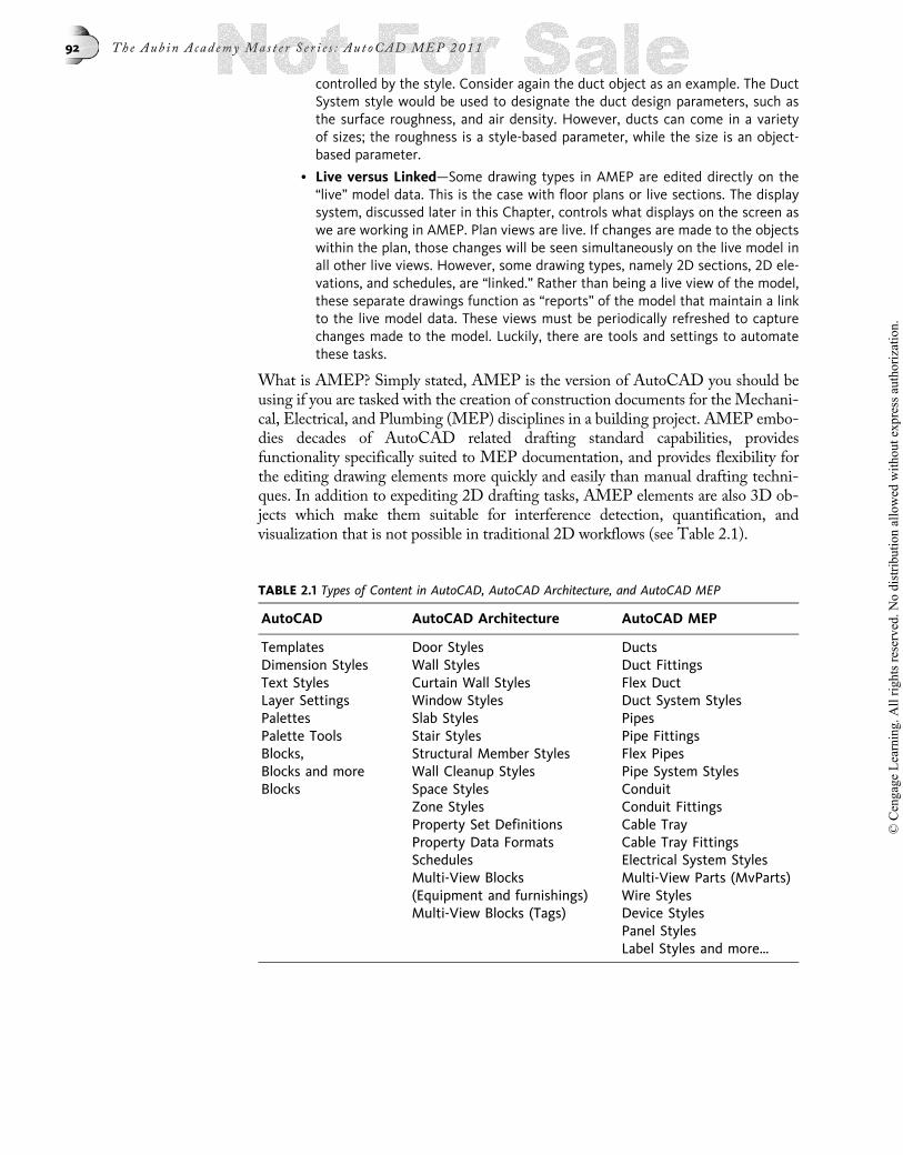
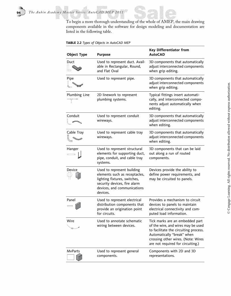
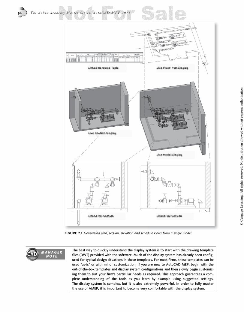
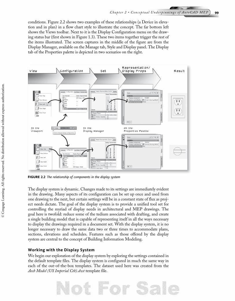
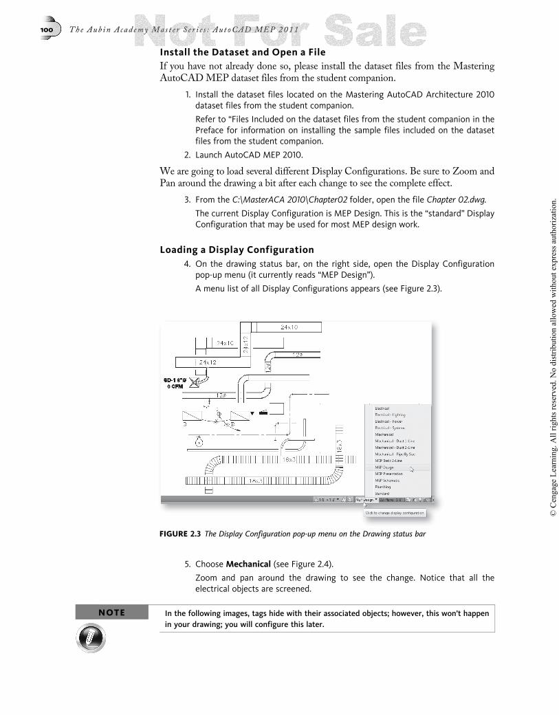
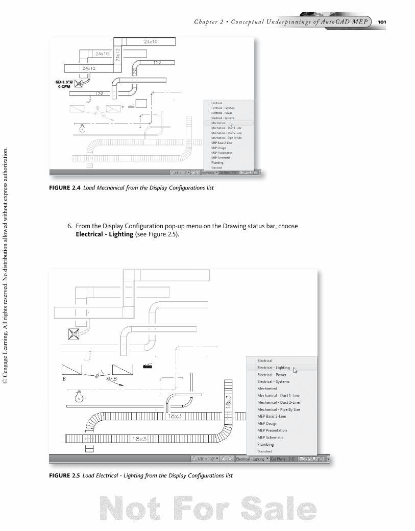
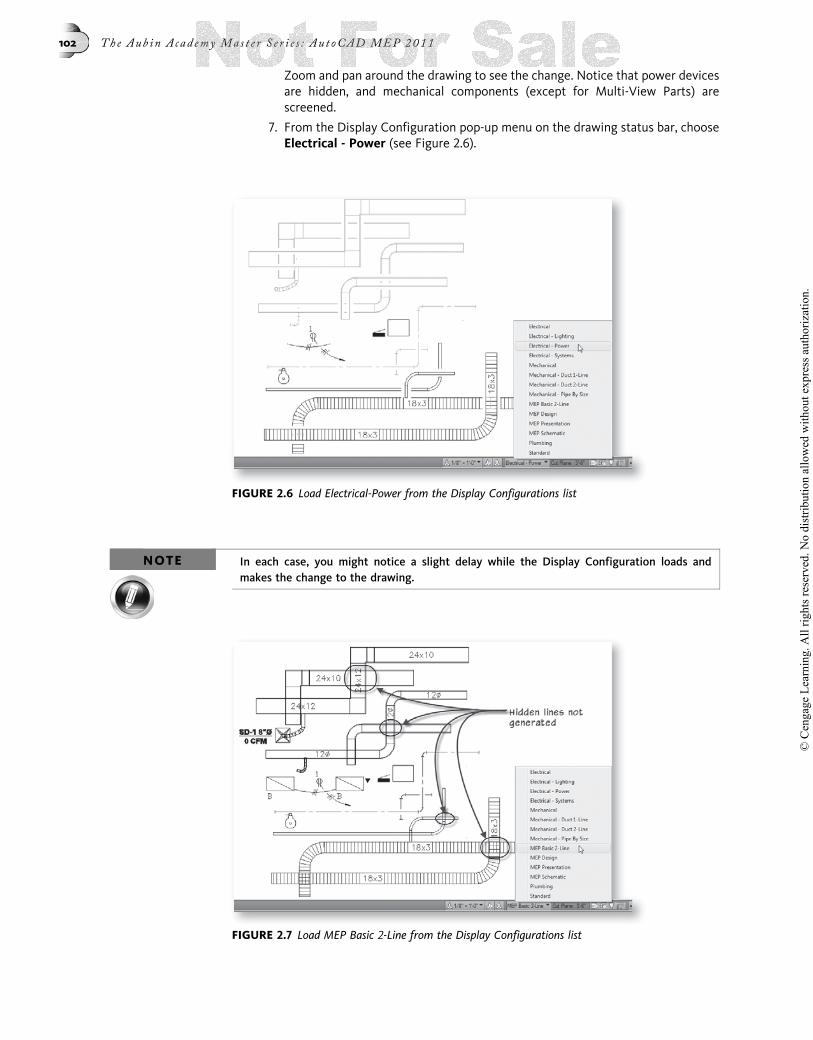
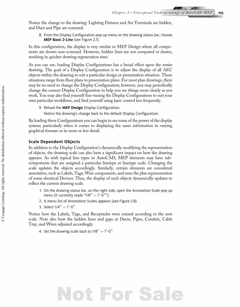
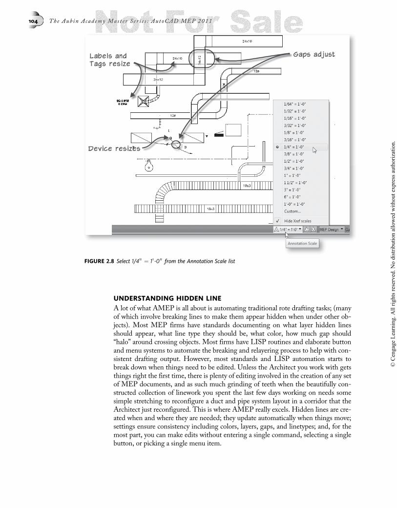
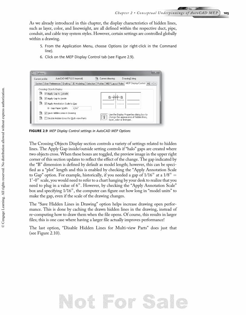

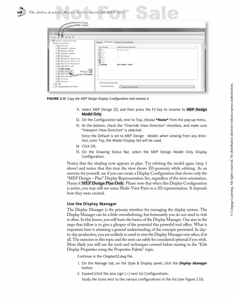
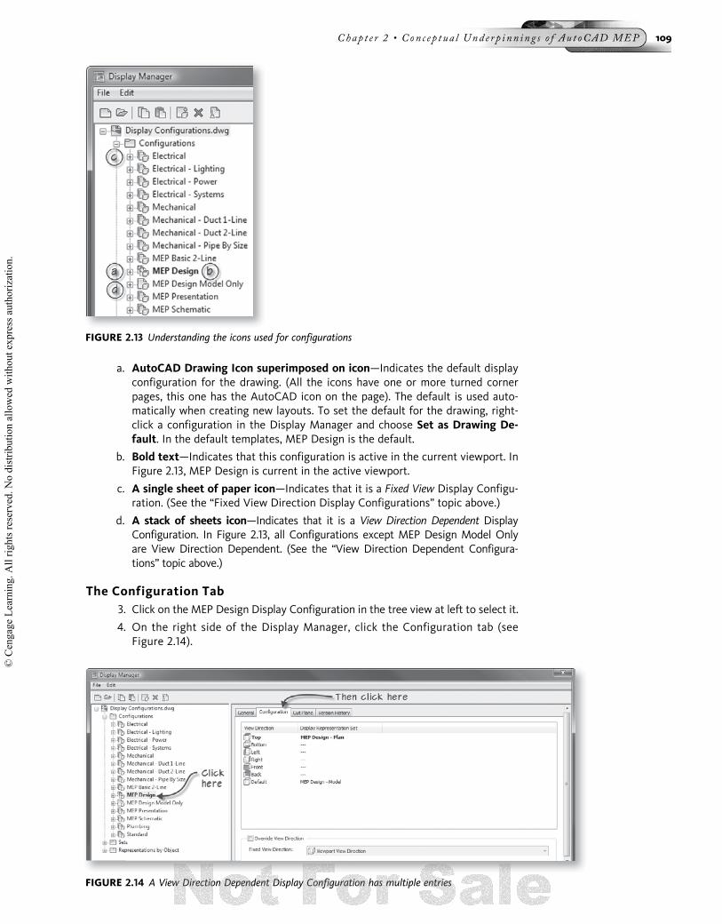
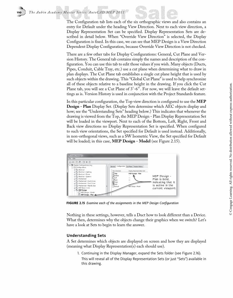
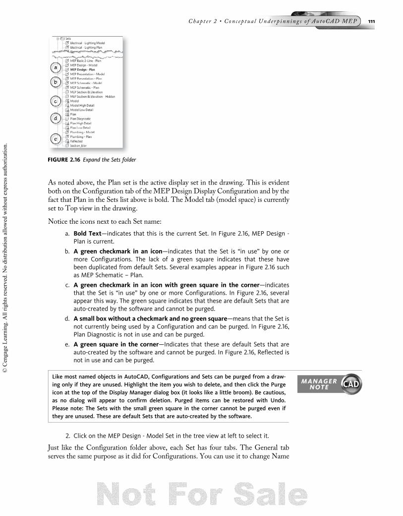
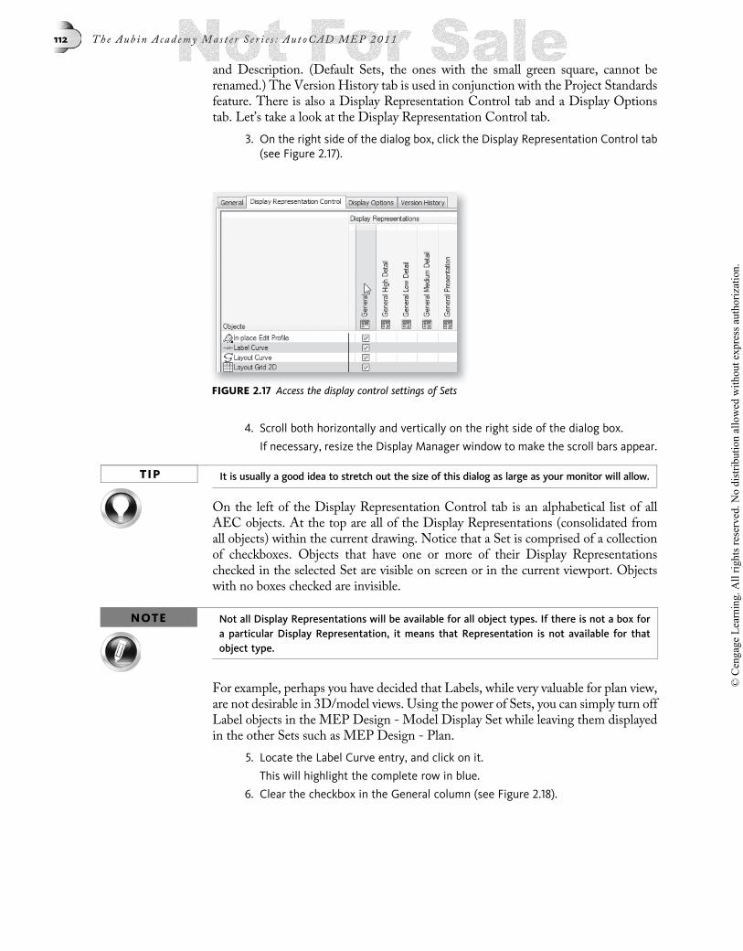
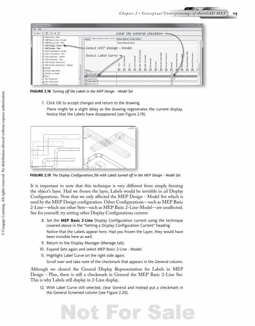
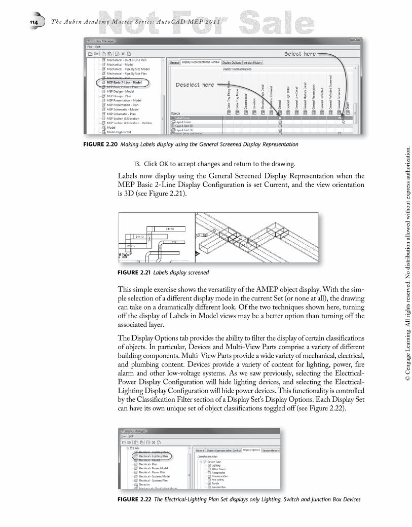
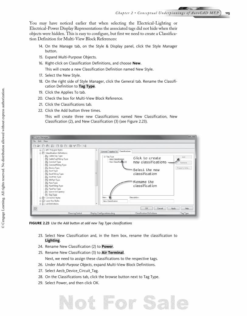

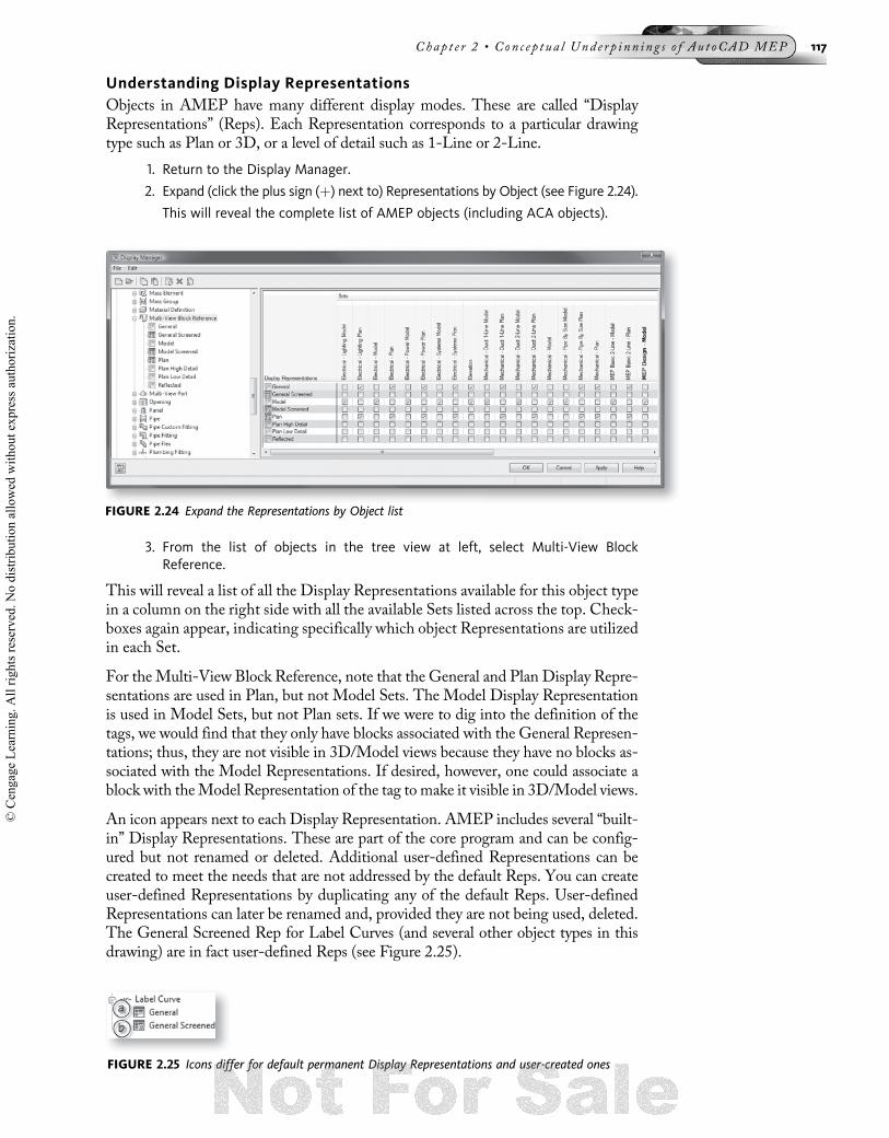
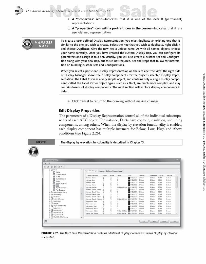
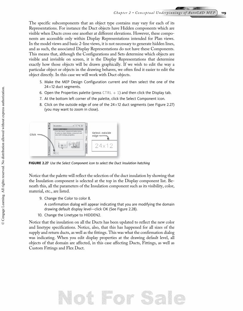
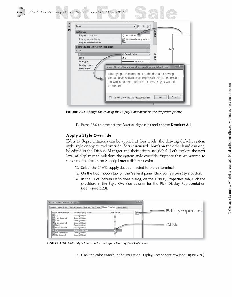
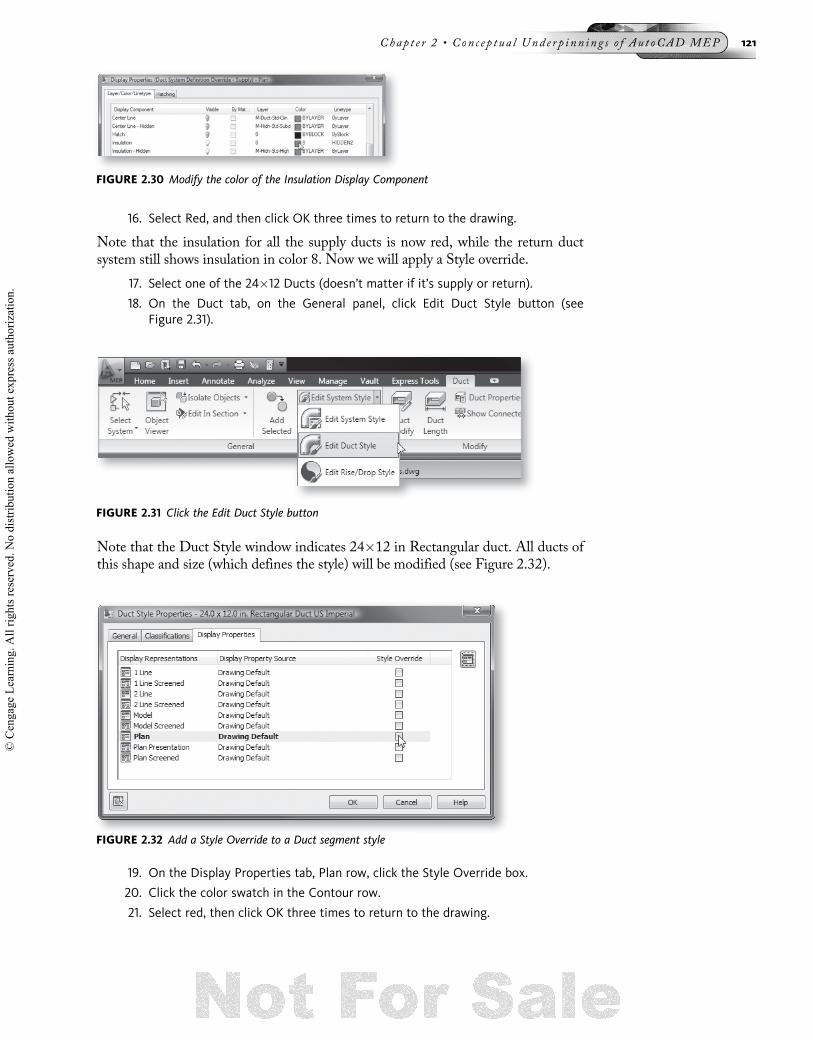
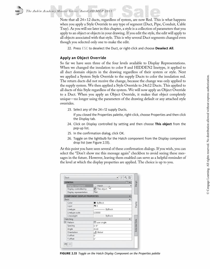
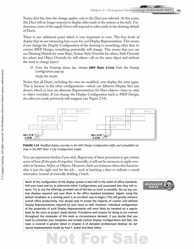
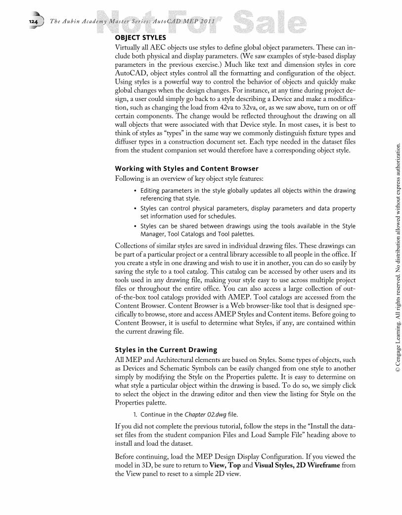
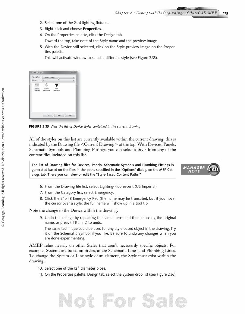
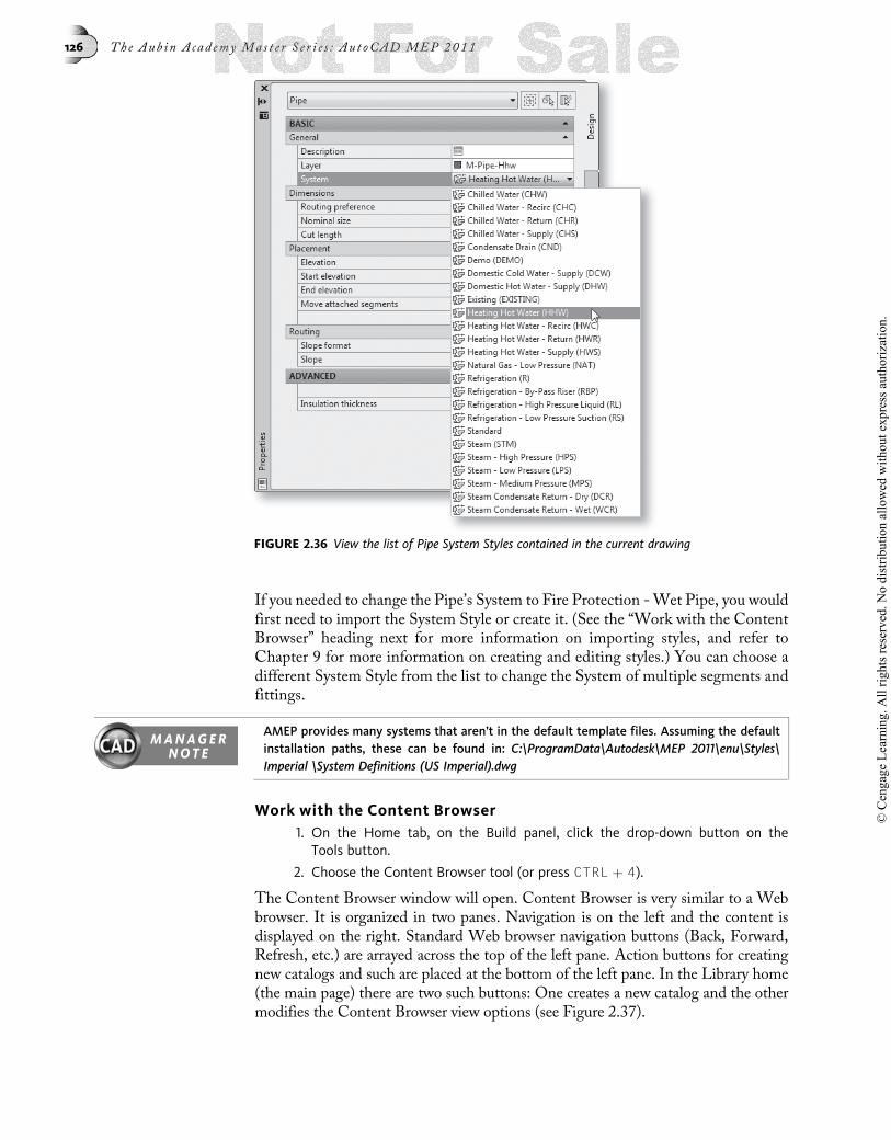
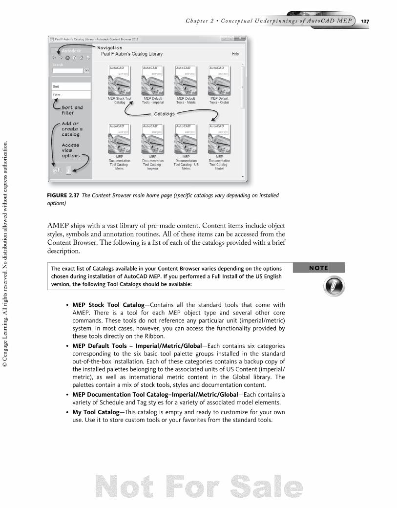

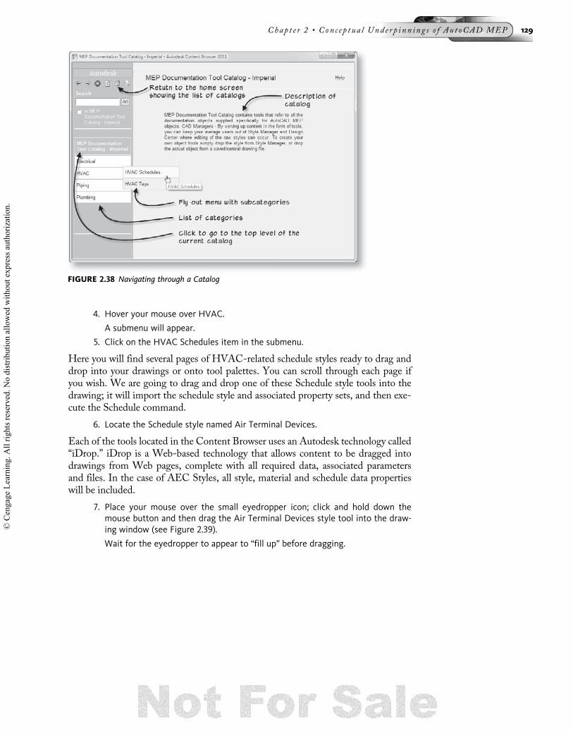

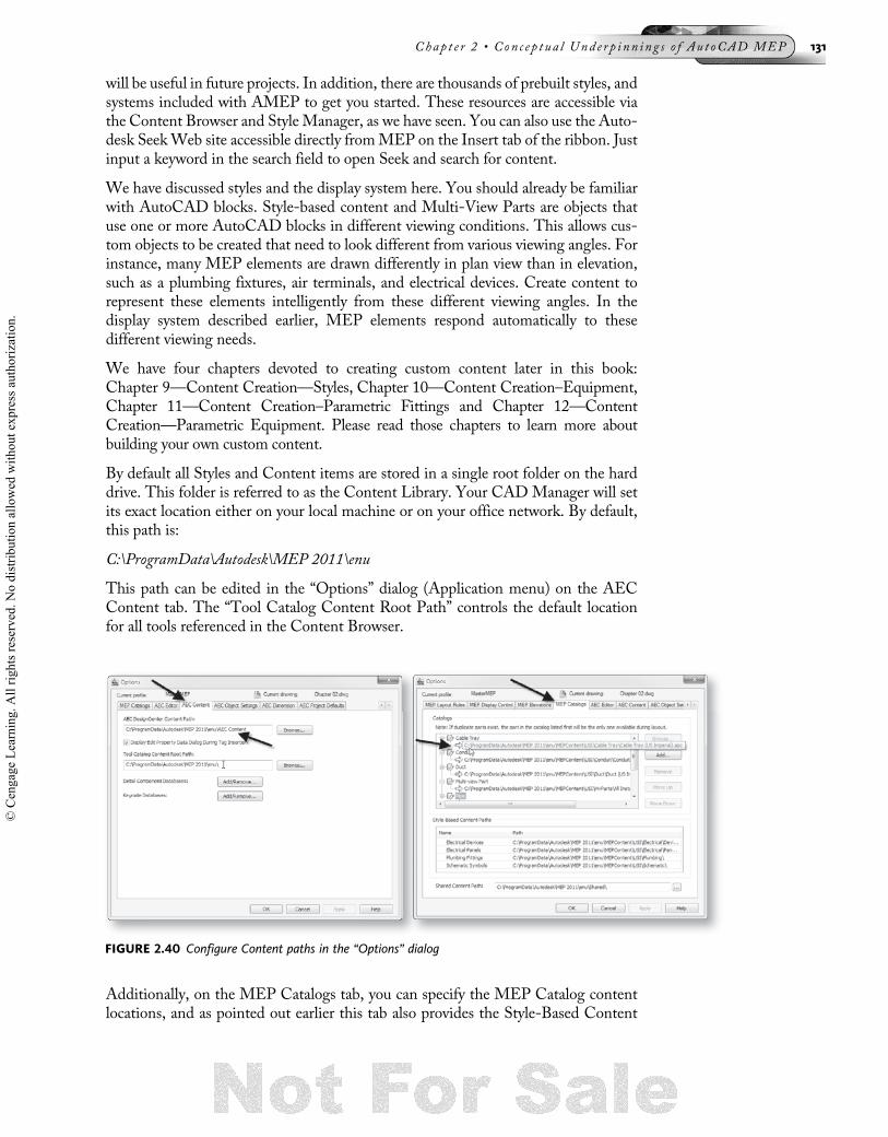


![[Challenge:Future] Moral underpinnings of capitalism](https://static.documents.pub/doc/80x56/54b9d28d4a7959982a8b457e/challengefuture-moral-underpinnings-of-capitalism-5584a6daf07c1.jpg)


