Conceptualization and Multi-Objective Optimization of the Electric System of an Airborne Wind Turbine J. W. Kolar et al. Swiss Federal Institute of Technology (ETH) Zurich Power Electronic Systems Laboratory www.pes.ee.ethz.ch
Transcript
1/88
Conceptualization and Multi-Objective Optimization of the Electric System of an
Airborne Wind Turbine
J. W. Kolar et al.
Swiss Federal Institute of Technology (ETH) Zurich Power Electronic Systems Laboratory
www.pes.ee.ethz.ch
2/88
Pareto-Optimal Design of Airborne Wind Turbine Power Electronics
J. W. Kolar, T. Friedli, F. Krismer, A. Looser, M. Schweizer, P. Steimer, J. Bevirt
Swiss Federal Institute of Technology (ETH) Zurich Power Electronic Systems Laboratory
www.pes.ee.ethz.ch
3/88
Outline
► ETH Zurich ► Power Electronic Systems Laboratory (PES) ► Out-of-the-Box Wind Turbine Concepts
Pumping Power Kites Airborne Wind Turbines
► Feasibility of AWT Electrical System
Electrical System Structure Multi-Objective Optimization (Weight vs. Efficiency) Controls Aspects
► Summary
4/88
Profile of ETH Zurich Dept. of ITET Power Electronic Systems Lab
5/88
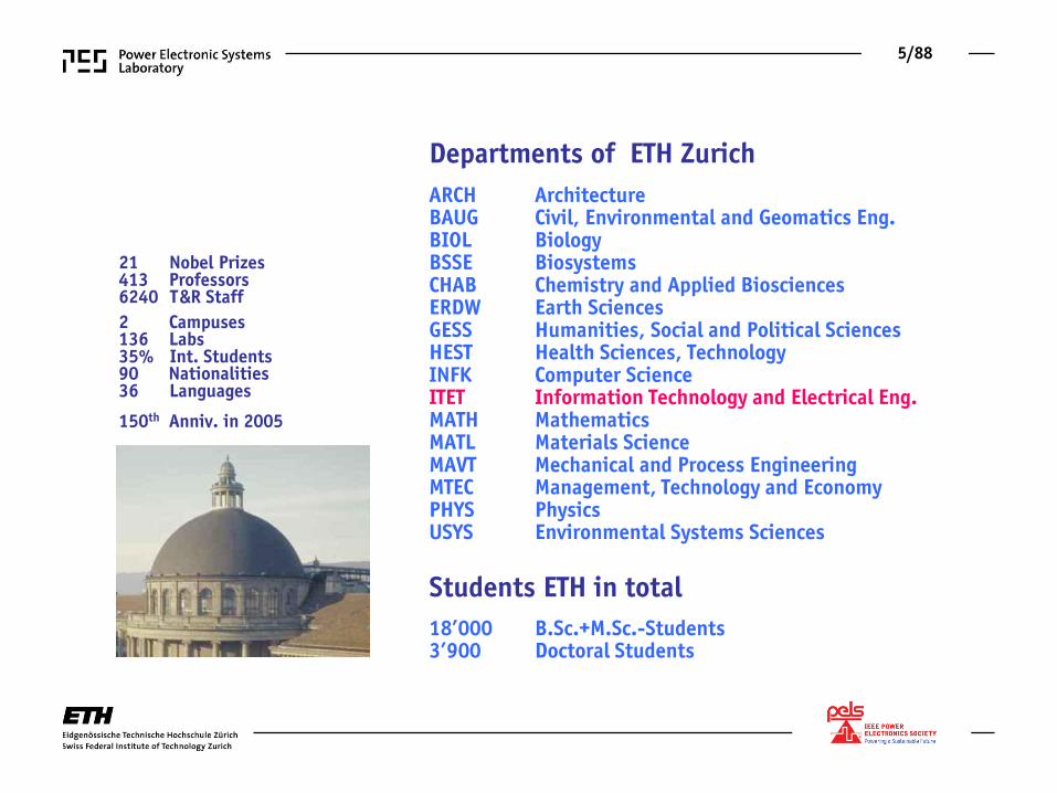
Departments of ETH Zurich
ARCH Architecture BAUG Civil, Environmental and Geomatics Eng. BIOL Biology BSSE Biosystems CHAB Chemistry and Applied Biosciences ERDW Earth Sciences GESS Humanities, Social and Political Sciences HEST Health Sciences, Technology INFK Computer Science ITET Information Technology and Electrical Eng. MATH Mathematics MATL Materials Science MAVT Mechanical and Process Engineering MTEC Management, Technology and Economy PHYS Physics USYS Environmental Systems Sciences
Students ETH in total
18’000 B.Sc.+M.Sc.-Students 3’900 Doctoral Students
21 Nobel Prizes 413 Professors 6240 T &R Staff
2 Campuses 136 Labs 35% Int. Students 90 Nationalities 36 Languages
150th Anniv. in 2005
6/88
Research in EE @ D-ITET
7/88
► Balance of Fundamental and Application Oriented Research
Power Semiconductors
Power Systems
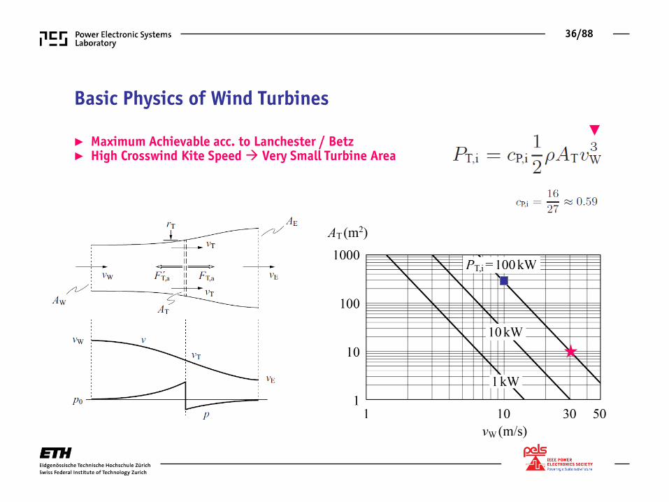
Advanced Mechatronic
Systems
High Voltage Technology
Power Electronic Systems
High Power Electronics
Energy Research Cluster @ D-ITET
8/88
► Balance of Fundamental and Application Oriented Research
Power Semiconductors
Power Systems
Mechatronic Actuator Systems
High Voltage Technology
Power Electronic Systems
High Power Electronics
Energy Research Cluster @ D-ITET
►
9/88
DC-AC Converter
D. Bortis
Y. Lobsiger B. Wrzecionko
R. Burkart H. Uemura
Power Electronic Systems Laboratory Johann W. Kolar
AC-DC Converter
F. Vancu
R. Bosshard S. Schroth
Ch. Marxgut
Pulsed Power
T. Soeiro
DC-DC Converter
J. Mühlethaler
T. Andersen D. Boillat
U. Badstübner M. Kasper St. Waffler
G. Ortiz
Multi-Domain Modeling
Industry Relations R. Coccia / B. Seiler
AC-AC Converter
M. Schweizer N. Widmer
A. Müsing
F. Giezendanner I. Kovacevic
A. Stupar
Mega-Speed Drives
T. Baumgartner A. Looser A. Tüysüz
Magnetic Levitation
M. Steinert T. Reichert
B. Warberger C. Zingerli F. Zürcher
Secretariat M. Kohn
Administration P. Albrecht / P. Maurantonio
Computer Systems C. Stucki
Electronics Laboratory P. Seitz
28 Ph.D. Students 4 Post Docs
Power Electronic Systems Laboratory
Leading Univ. in Europe
F. Krismer
►
10/88
Power Electronics
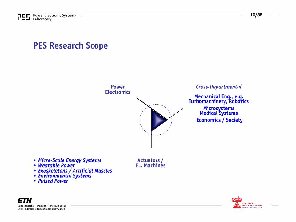
Cross-Departmental
Mechanical Eng., e.g. Turbomachinery, Robotics
Microsystems Medical Systems
Economics / Society
Actuators / EL. Machines
PES Research Scope
• Micro-Scale Energy Systems • Wearable Power • Exoskeletons / Artificial Muscles • Environmental Systems • Pulsed Power
11/88
Industry Collaboration
• Automotive Systems • More-Electric Aircraft • Renewable Energy • Semiconductor Process Technology • Medical Systems • Industry Automation • Etc.
► 16 International Industry Partners
► Core Application Areas
PES Research Budget
2/3 Industry Share
Strategic Research
Industry Related Research
12/88
General Research Approach
13/88
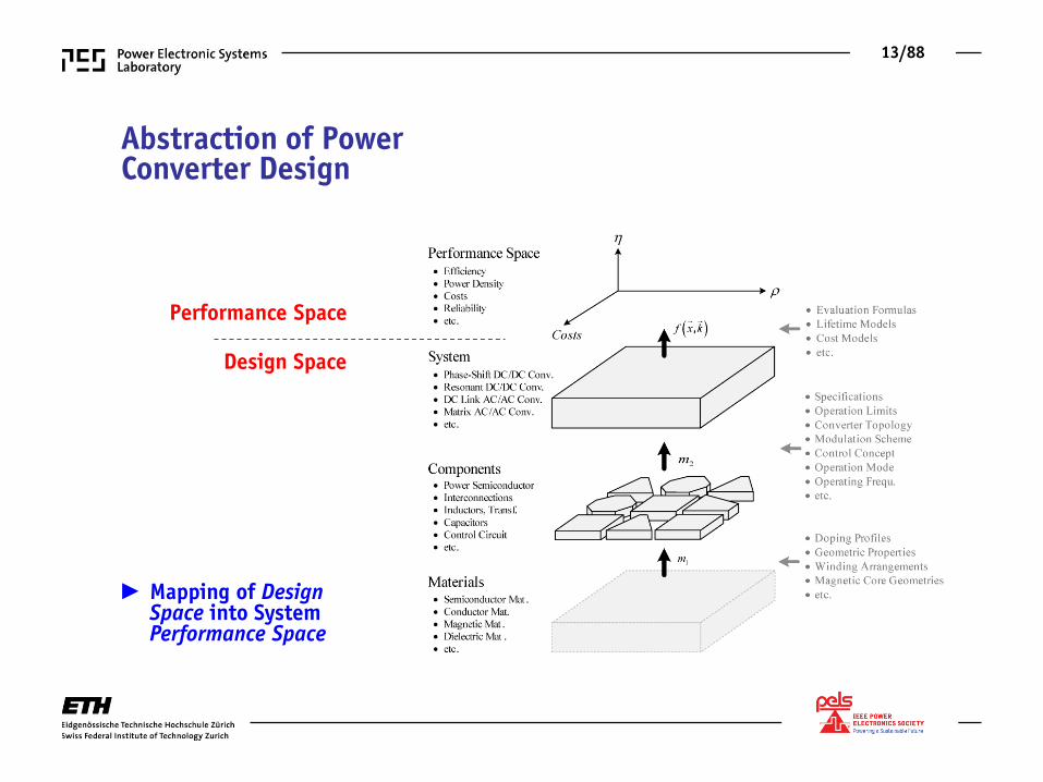
► Mapping of Design Space into System Performance Space
Abstraction of Power Converter Design
Performance Space
Design Space
14/88
Mathematical Modeling and Optimization of Converter Design
15/88
► Sensitivity to Technology Advancements ► Trade-off Analysis
Technology Sensitivity Analysis Based on η-ρ-Pareto Front
16/88
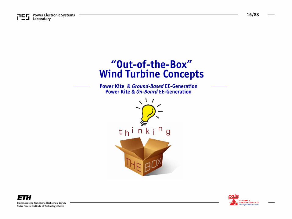
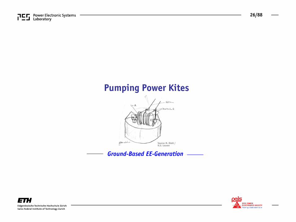
“Out-of-the-Box” Wind Turbine Concepts Power Kite & Ground-Based EE-Generation
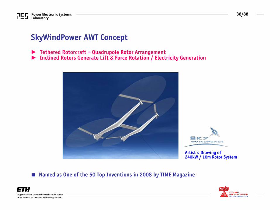
■ Named as One of the 50 Top Inventions in 2008 by TIME Magazine
39/88
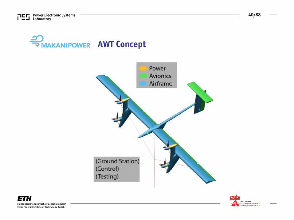
► Reinforced Tether Transfers MV-Electricity to Ground ► Composite Tether also Provides Mechanical Connection to Ground
AWT Concept
40/88
AWT Concept
41/88
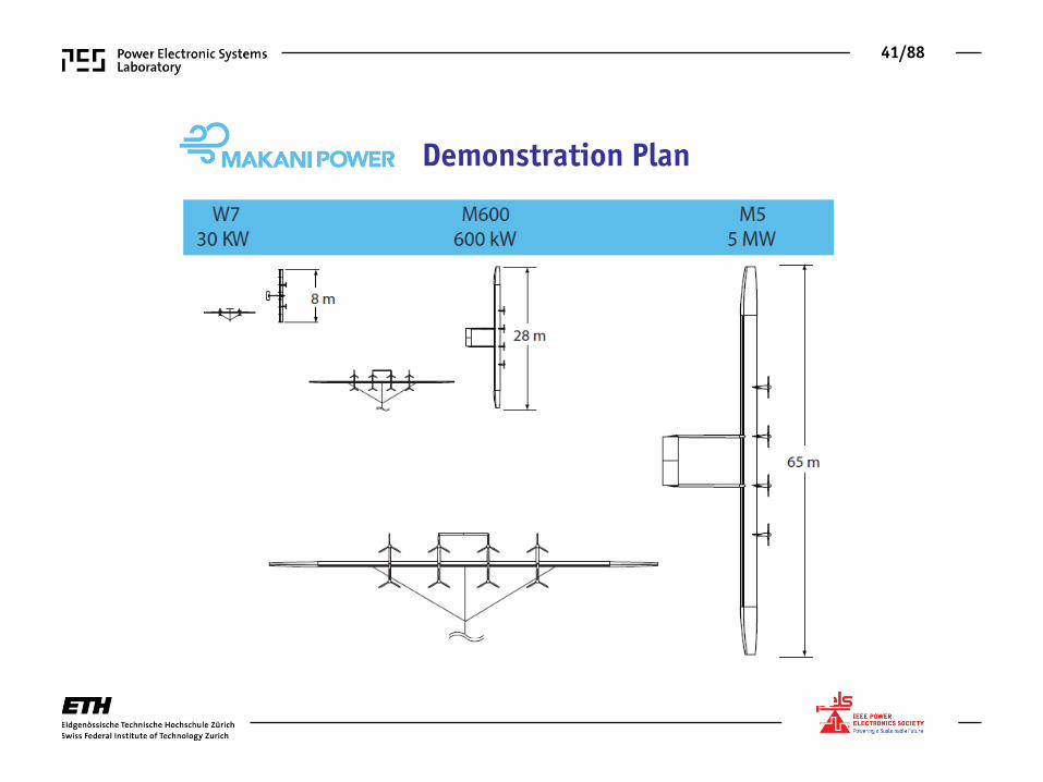
Demonstration Plan
42/88
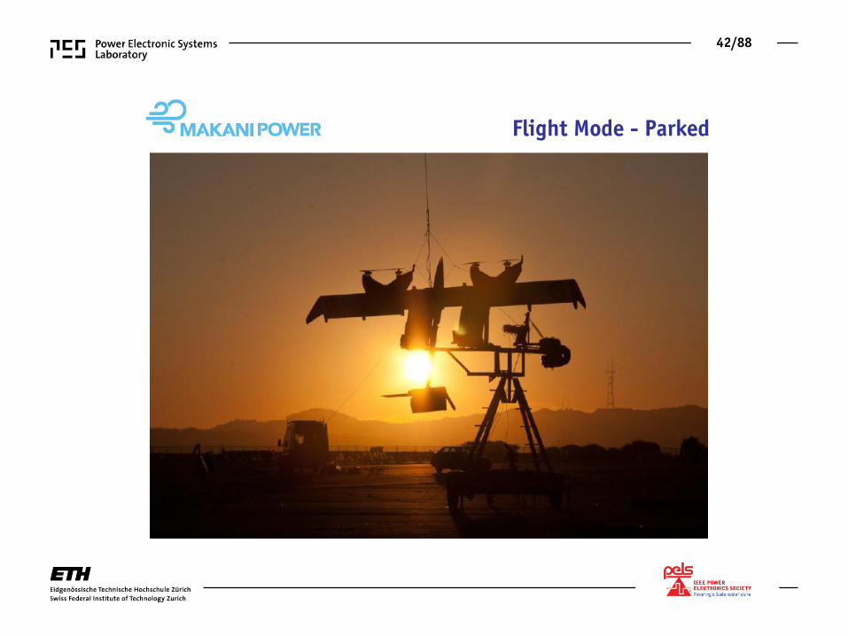
Flight Mode - Parked
43/88
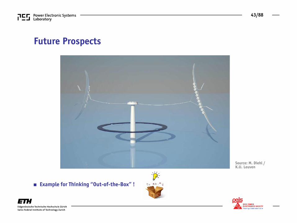
Future Prospects
■ Example for Thinking “Out-of-the-Box” !
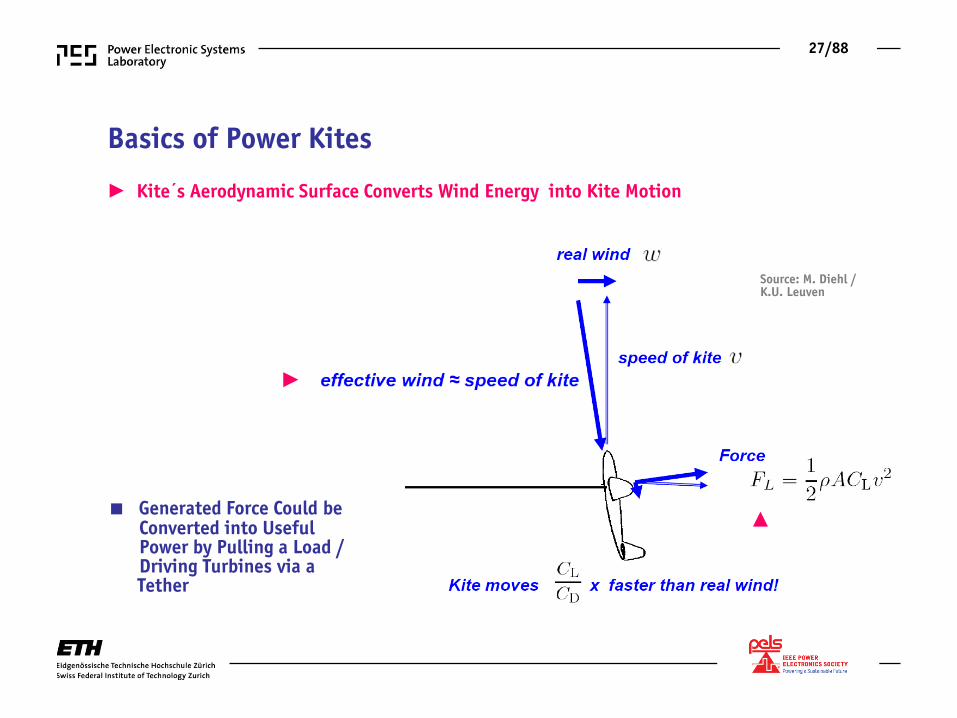
Source: M. Diehl / K.U. Leuven
44/88
Future Prospects Future Prospects
Source: M. Diehl / K.U. Leuven
■ Example for Thinking “Out-of-the-Box” !
45/88
Technical Feasibility of AWT Electrical System ► AWT Electrical System Structure ► Multi-Objective Optimization (Weight vs. Efficiency) ► Controls Aspects
46/88
AWT Basic Electrical System Structure
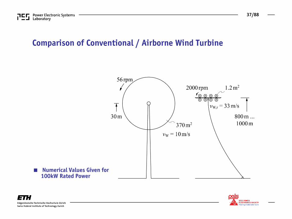
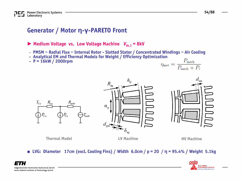
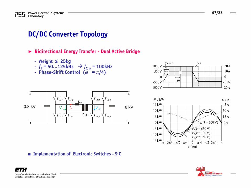
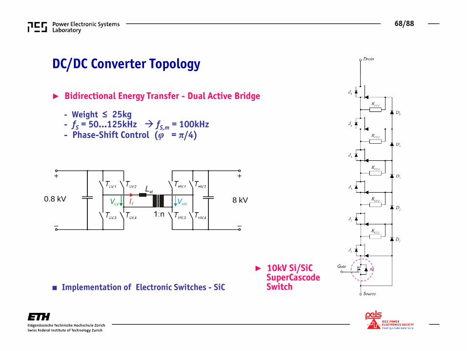
► Rated Power 100kW ► Operating Height 800…1000m ► Ambient Temp. 40°C ► Power Flow Motor & Generator
■ El. System Target Weight 100kg ■ Efficiency (incl. Tether) 90% ■ Turbine /Motor 2000/3000rpm
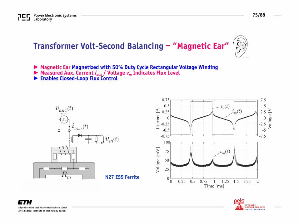
► Magnetic Ear Magnetized with 50% Duty Cycle Rectangular Voltage Winding ► Measured Aux. Current iaux / Voltage vm Indicates Flux Level ► Enables Closed-Loop Flux Control
N27 E55 Ferrite
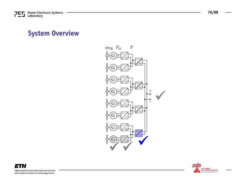
76/88
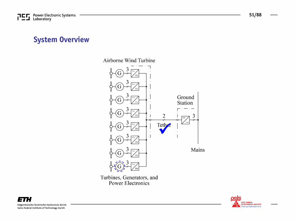
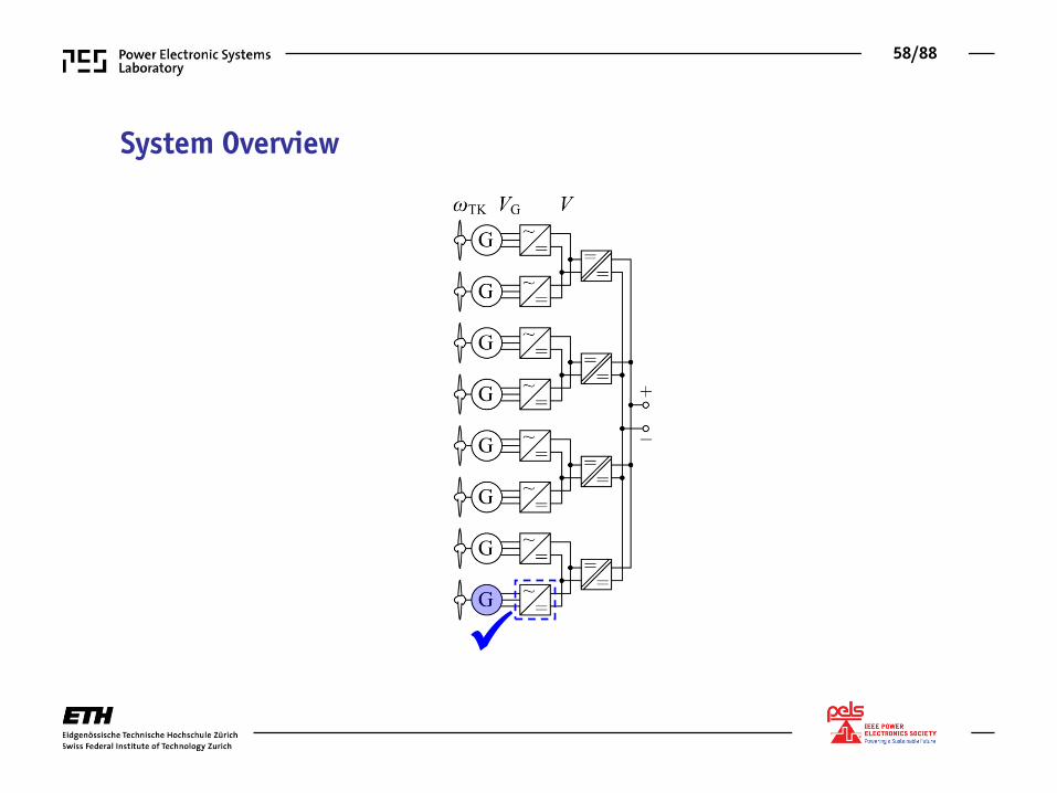
System Overview
77/88
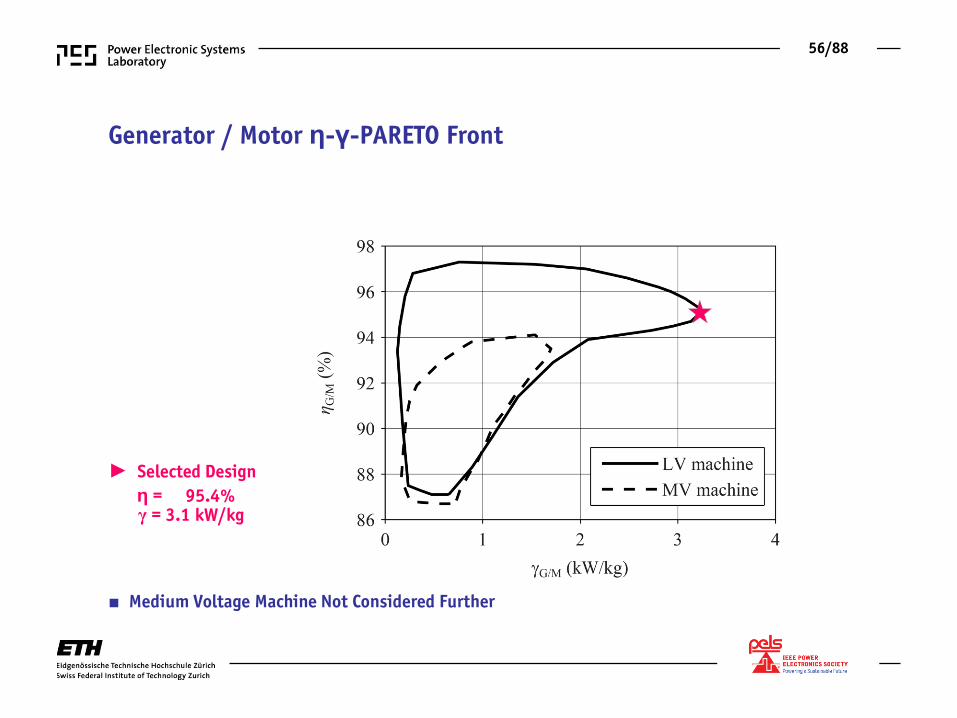
Overall System Consideration Total Weight
Overall Efficiency η-γ-PARETO Front
78/88
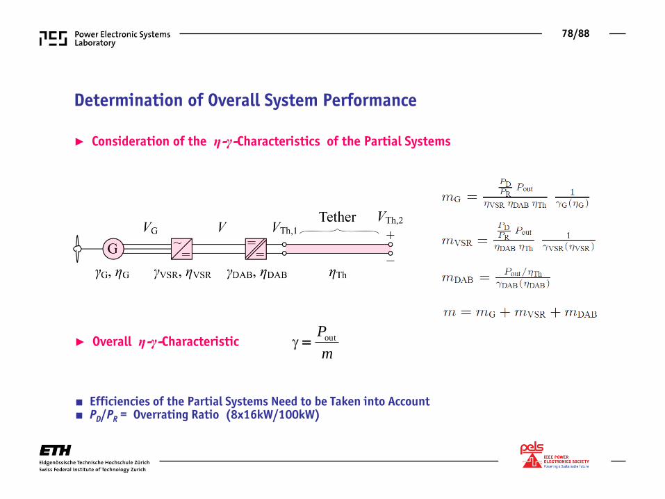
Determination of Overall System Performance
► Consideration of the η-γ-Characteristics of the Partial Systems
■ Efficiencies of the Partial Systems Need to be Taken into Account ■ PD/PR = Overrating Ratio (8x16kW/100kW)
► Overall η-γ-Characteristic outP
m
79/88
Overall System Performance
■ Final Step: System Control Consideration
►
80/88
Electric System Control Stability
Reference Response Disturbance Response
81/88
System Control
► Control of Flight Trajectory / Max. Energy Generation ► Generator (Motor) Speed / Torque Control ► etc. ► Control of DC Voltage Levels is Mandatory !
■ Simplified Control-Oriented Block Diagram of the Electric System
82/88
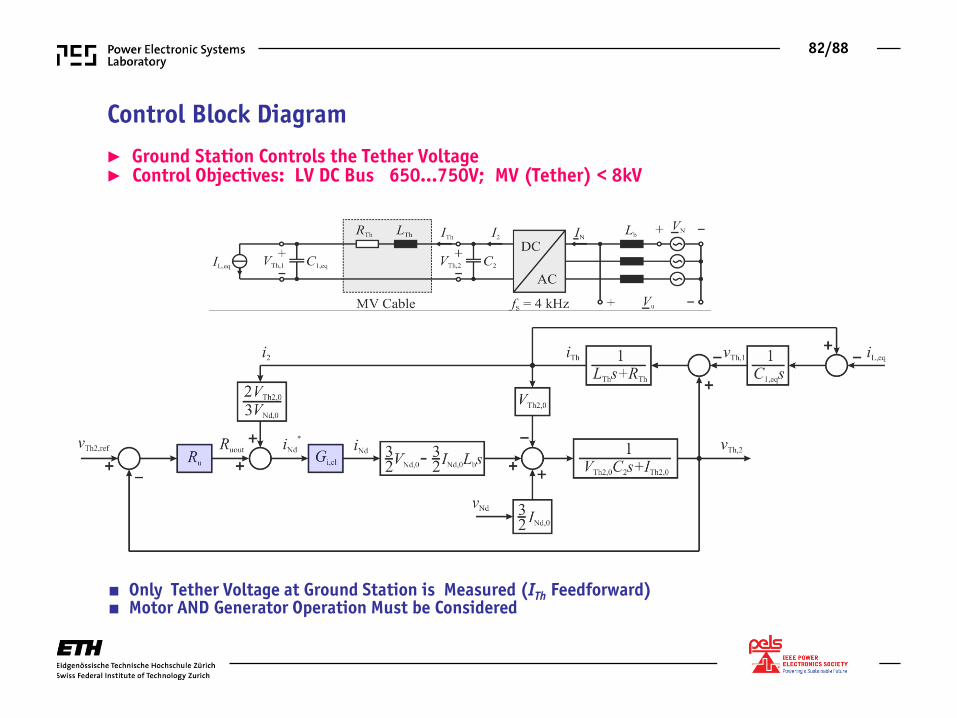
Control Block Diagram
► Ground Station Controls the Tether Voltage ► Control Objectives: LV DC Bus 650…750V; MV (Tether) < 8kV
■ Only Tether Voltage at Ground Station is Measured (ITh Feedforward) ■ Motor AND Generator Operation Must be Considered
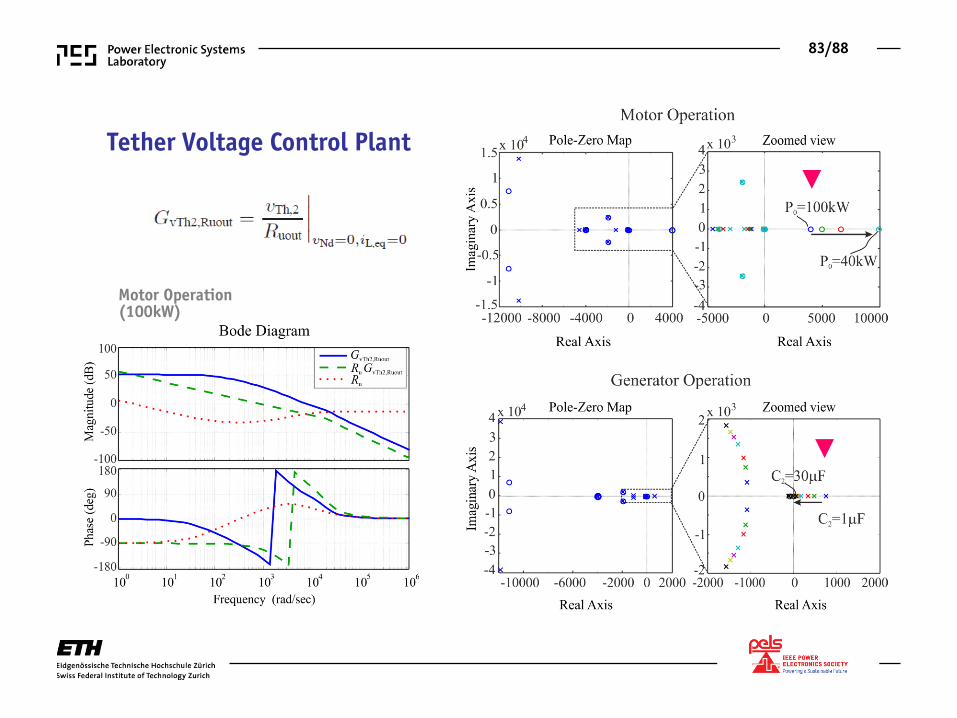
83/88
Tether Voltage Control Plant ►
►
Motor Operation (100kW)
84/88
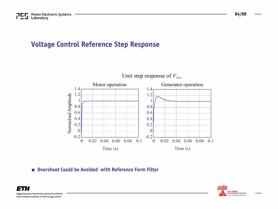
Voltage Control Reference Step Response
■ Overshoot Could be Avoided with Reference Form Filter
85/88
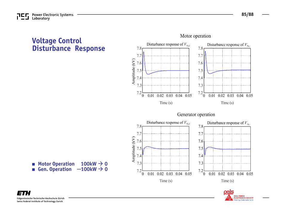
Voltage Control Disturbance Response
■ Motor Operation 100kW 0 ■ Gen. Operation ─100kW 0
86/88
► AWTs are Basically Technically Feasible ► AWTs Realization Combines Numerous Challenges - Aircraft Design - MVDC Transmission - MV/HF Power Electronics - etc. ► AWTs are a Highly Interesting Example for η-γ Trade-off Studies ► AWTs are Examples for Smart Pico Grids or MEA Power System Analysis ► AWTs is a Clear Example of Thinking “Out-of-the-Box” !