Light Water Reactor Sustainability R&D Program Concrete Aging and Degradation in NPPs LWRS Activities J.T. Busby, K.G. Field, Y. Le Pape, C. Mattus, D.J. Naus, I. Remec, T.M. Rosseel Oak Ridge National Laboratory MEETING BETWEEN THE U.S. NUCLEAR REGULATORY COMMISSION STAFF AND INDUSTRY TO DISCUSS SUBSEQUENT LICENSE RENEWAL Concrete and Civil Structures December 5, 2013
Transcript
Light Water Reactor Sustainability R&D Program
Concrete Aging and Degradation in NPPs
LWRS Activities
J.T. Busby, K.G. Field, Y. Le Pape, C. Mattus, D.J. Naus, I. Remec, T.M. Rosseel
Oak Ridge National Laboratory
MEETING BETWEEN THE U.S. NUCLEAR REGULATORY COMMISSION STAFF AND
INDUSTRY TO DISCUSS SUBSEQUENT LICENSE RENEWAL
Concrete and Civil Structures December 5, 2013
DOE’s LWRS Program
Materials Aging and Degradation path addresses: reactor metals,
concrete, cables, buried piping, and mitigation strategies. The strategic goals of the pathway are to develop the scientific basis for understanding and predicting long-term environmental degradation behavior of materials in nuclear power plants and to provide data and methods to assess performance of systems, structures, and components essential to safe and sustained nuclear power plant operations.
Introduction: motivation In the last 15 years more than 70 NPPs in the US have undergone a license renewal process to extend their lifetime up to 60 years.
Extensions to 80 years and beyond are being considered to meet the future national energy demands.
Concrete degradation was identified as a subject of interest for extended NPPs operation.
Identified priorities for Containment/Shield/Bio-Shield/RPV Supports and buildings:
– Radiation (Part I)
– Alkali-Aggregate/Silica Reaction (Part II)
– Creep/creep-fracture interaction (Roadmap to be developed)
Part I- Irradiated Concrete
Research results provided: 2012-2016
Why concrete: the Hilsdorf curve
Current understanding of radiation effects on concrete is largely based on the ‘Hilsdorf curve,’ dating back to 1978. Gaps in information: the neutron fluence cutoff energy, the composition of concrete, the irradiation temperature, gamma-ray dose, etc. Therefore: the applicability to NPP concrete is uncertain; more data needed.
Project Strategy – Irradiation
• Characterize radiation fields in concrete structures in NPPs and determine the bounding values of neutron fluence and gamma-ray dose in the biological shield concrete at 80 years of operation and beyond.
• Obtain more data on the effects of neutron and gamma irradiation as well as extended time at elevated temperature on concrete. • Develop a more exhaustive database including recently unclassified data • Irradiate prototypical concrete to levels equal to or greater than expected in
extended service (accelerated irradiation studies) and evaluate possible degradation.
• Harvest and test irradiated concrete from decommissioned plants (US and international).
• Develop a more robust fundamental understanding of the effects of radiation on concrete.
• Establish a collaborative research effort with international partners.
Project Strategy - Irradiation
• Characterize radiation fields in concrete structures in NPPs and determine the bounding values of neutron fluence and gamma-ray dose in the biological shield concrete at 80 years of operation and beyond.
• Obtain more data on the effects of neutron and gamma irradiation as well as extended time at elevated temperature on concrete. • Irradiate prototypical concrete to levels equal to or greater than expected in
extended service (accelerated irradiation studies) and evaluate possible degradation.
• Harvest and test irradiated concrete from decommissioned plants (US and international).
• Develop a more robust fundamental understanding of the effects of radiation on concrete.
• Establish a collaborative research effort with international partners.
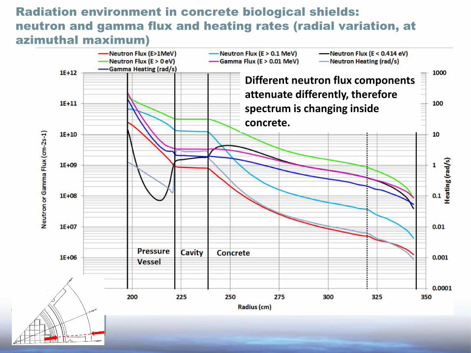
Characterization of radiation fields in concrete of the biological shields
Performed coupled neutron and gamma-ray transport calculations for one selected 2-loop and one 3-loop plant
Reviewed publicly available reactor pressure vessel surveillance reports for relevant data (work in progress)
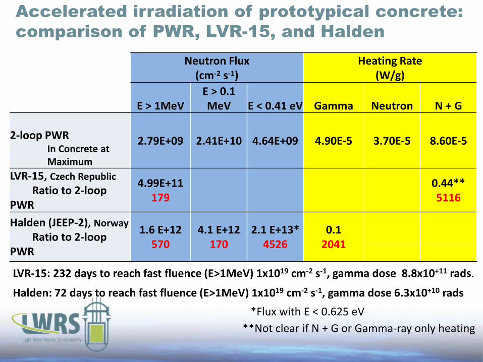
Accelerated irradiation of prototypical concrete: comparison of PWR, LVR-15, and Halden
*Flux with E < 0.625 eV **Not clear if N + G or Gamma-ray only heating
LVR-15: 232 days to reach fast fluence (E>1MeV) 1x1019 cm-2 s-1, gamma dose 8.8x10+11 rads.
Halden: 72 days to reach fast fluence (E>1MeV) 1x1019 cm-2 s-1, gamma dose 6.3x10+10 rads
Summary US reactor fleet bounding fluence:
– Based on estimated fluence levels in biological shields and available data on concrete strength versus fluence, concrete degradation within 80 years of plant operation can not be ruled out.
– Neutron fluence “energy cutoff” (if any) needs to be carefully assessed. – If the “fluence threshold,” above which the degradation of concrete occurs
can be specified in terms of fast neutron fluence (E > 1 MeV), then data from the RPV surveillance programs could be sufficient to bound the conditions of concrete in NPPs.
– Since the relevant irradiation parameter for concrete is not established it is desirable to obtain full neutron and gamma spectra in the samples for the experiment.
– For the concrete irradiation experiments it is desirable to use neutron and gamma spectra similar to those in the actual plants. However, neutron spectrum changes significantly through the biological shield.
– For relatively small concrete samples it may be difficult to obtain gradients similar to those in biological shields. It may be better to try to obtain “uniform” irradiation through the samples.
Accelerated irradiation experiments:
Project Strategy
• Characterize radiation fields in concrete structures in NPPs and determine the bounding values of neutron fluence and gamma-ray dose in the biological shield concrete at 80 years of operation and beyond.
• Obtain more data on the effects of neutron and gamma irradiation as well as extended time at elevated temperature on concrete. • Develop a more exhaustive database including recently unclassified data • Irradiate prototypical concrete to levels equal to or greater than expected in
extended service (accelerated irradiation studies) and evaluate possible degradation.
• Harvest and test irradiated concrete from decommissioned plants (US and international).
• Develop a more robust fundamental understanding of the effects of radiation on concrete.
• Establish a collaborative research effort with international partners.
Literature review of compression strength of irradiated concrete
Hilsdorf et al. Upper Bound
Larger dataset supports downward sloping trend in compressive strength but requires filtering for commercial NPP applicability
Most data at high fluence are also at elevated temperatures, >100 °C (grey symbols) or/and with particular shielding concrete
Possible degradation of properties near LWR fleet end-of-life
Hilsdorf, H.K. et al. (1978) ORNL (2013)
2-loop PWR 80 years E > 0.0 MeV
2-loop PWR 80 years E > 0.1 MeV
2-loop PWR 80 years E > 1.0 MeV
Project Strategy - Irradiation
• Characterize radiation fields in concrete structures in NPPs and determine the bounding values of neutron fluence and gamma-ray dose in the biological shield concrete at 80 years of operation and beyond.
• Obtain more data on the effects of neutron and gamma irradiation as well as extended time at elevated temperature on concrete. • Develop a more exhaustive database including recently unclassified data • Irradiate prototypical concrete to levels equal to or greater than expected in
extended service (accelerated irradiation studies) and evaluate possible degradation.
• Harvest and test irradiated concrete from decommissioned plants (US and international).
• Develop a more robust fundamental understanding of the effects of radiation on concrete.
• Establish a collaborative research effort with international partners.
Summary of possible radiation induced effects on cement and aggregate
Paste
• Densification of phases present • Water loss • Increase in meso-pore density
Aggregate
• Thermal expansion
Heating and Drying
*Slide based on Maruyama, I. “Introduction of Concrete Research in JAMPSS Program” July, 30 2013.
Paste
• Water decomposition due to radiolysis
• New phase(s) formation
Aggregate
• Elevate temperature due to gamma heating
• Possible radiation damage
Gamma Rays
Neutrons
Aggregate
• Expansion due to amorphization (radiation damage)
Paste
• Water decomposition due to radiolysis
• Limited radiation damage
Materials modeling
Damaged Shrinking Cement Paste
Irradiation Damaged Swelling Aggregate
Hashin Composite Concrete Cell
INTERACTION
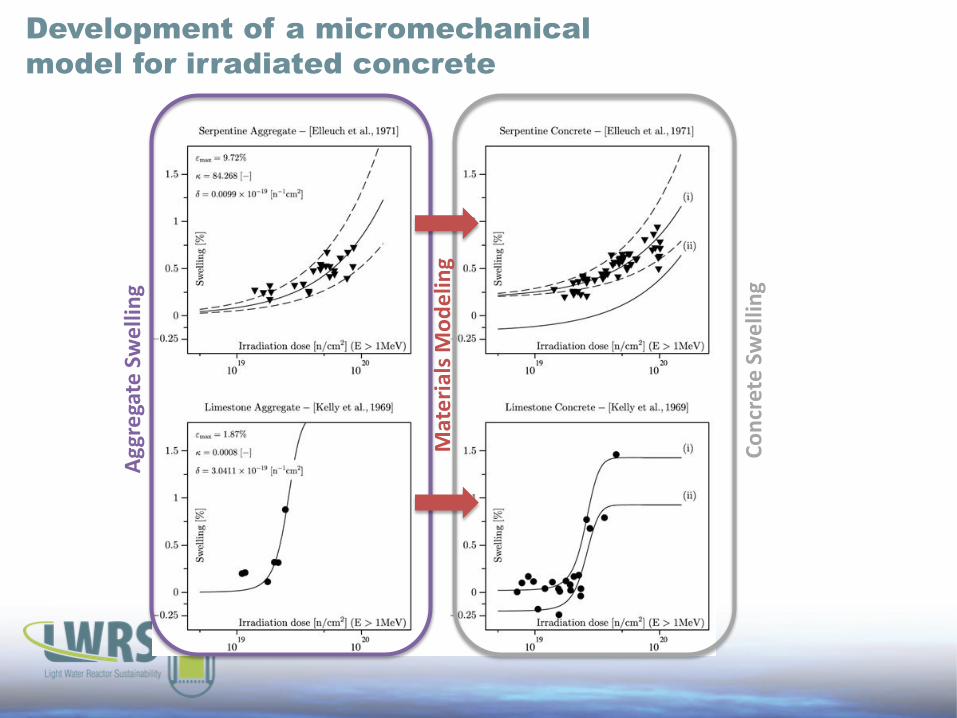
Development of a micromechanical model for irradiated concrete
Agg
rega
te S
wel
ling
Conc
rete
Sw
ellin
g
Mat
eria
ls M
odel
ing
Summary on radiation effects in concrete • Expansion is possible for aggregates and concretes
exposed to neutrons - Different aggregate types swelled at different rates - Expansion ן % silicate amorphization
• Mechanical properties (elastic modulus, tensile strength, compressive strength) are all changed at fluences above 1x10¹⁹ n/cm2
– Close to bounding fluence for all PWR reactor types at 80+ years operation
• Future experiments are needed to answer open questions on irradiated concrete – Future experiments require several important variables to
be evaluated for the aggregate, paste, and concrete separately (Mass change, length change/swelling, strength, elastic modulus, % amorphization, aggregate phase volume fraction)
• Structural significance to be investigated – Combine simulation/experiment to determine change of
properties – Account for neutron, gamma, temperature, humidity
gradients
[1] Dubrovskii, V.B. et al. “ Radiation Damage in Ordinary Concrete,” Atomnaya Energiya, October 1967
Part II- Alkali-Silica Reaction
Research results provided: 2014-2017
www.cmc-concrete.com
www.chaneyenterprises.com
www.borealwater.com
reactive silica
water
expensive gel resulting from the alkali-silica reaction
www.fhwa.dot.gov
+
+
=
cement alkali
And absorbs
Reacts with Thermal activation (accelerated test 100oF)
Need at least ~70% of moisture content
Alkali-Silica Reaction in a Nutshell 1/2
Alkali-Silica Reaction in a Nutshell 2/2
• Expansion of Concrete resulting from the reaction between alkali (generally from cement), reactive aggregate (like amorphous silica) and water absorption – Causes expansion, cracking, loss mechanical properties – Common mechanisms for dams (age, high moisture content) – One recent occurrence at a nuclear power plant in the U.S. – DOT study showed more than 70% of the states have experienced ASR
related issues of their infrastructures
• Questions: – Likelihood of occurrence – Significance for Safety-Related Structures (containment bldg, reactor
cavity, SFP…)
Project Strategy – Alkali-Silica Reaction
• Characterize temperature and moisture fields in concrete structures in NPPs at 80 years of operation and beyond.
• Develop a solid assessment of the structural significance of ASR . • Investigate the role of stress confinement on the development of ASR
in thick reinforced/prestressed structures • Investigate the effect of ASR on the residual structural resistance of
thick reinforced/prestressed structures • Develop innovative means of monitoring
• Establish a collaborative research effort with national/international partners.
Project Strategy – Alkali-Silica Reaction
• Characterize temperature and moisture fields in concrete structures in NPPs at 80 years of operation and beyond.
• Develop a solid assessment of the structural significance of ASR . • Investigate the role of stress confinement on the development of ASR in
thick reinforced/prestressed structures • Investigate the effect of ASR on the residual structural resistance of thick
reinforced/prestressed structures • Develop innovative means of monitoring
• Establish a collaborative research effort with international partners.
Structural Significance: Residual Shear Capacity
r
z
T�
Vzz
VTT�
Hzz
HTT�
Hrr
Hrr
Pattern cracking Orthotropic cracking
Hrr
VTT�
damage
time
mechanical variables
PAST
NOW
Vzz
VTT�
Hzz
HTT�
Hrr
Impact on the Residual Shear Capacity Safety Margin? ASR swelling
FUTURE
Courtesy of Pr. V. Saouma (U. of Colorado)
Integrated Aging Management
Objectives 1. Interpretation of the test results 2. Transposition from the laboratory/simulation to the actual structure 3. Accounting for the uncertainties (unreinforced concrete shear strength
exhibits important scattering)
Pathways 1. Develop a highly instrumented large-scale mockup including stress
confinement 2. Use non linear numerical simulation for understanding the role of
anisotropic damage in shear fracture propagation
Blending Experimental and Numerical Simulations
MATERIALS SCIENCE - basic mechanisms - lab tests
MONITORING - feed-back - bayesian approach
COMPUTATION TH-M FEA
FEM/MONITORING PREDICTION
Simulation of ASR Structural Effects on Dams / EDF experience
Courtesy of
Simulation of Transmission Towers (TEPCO)
Deterministic Modeling • Orthotropic damage modeling of ASR damage [Capra & Sellier, 2003], [Saouma & Perotti, 2006] • Propagation of shear fracture in an orthotropic damaged materials
Objective - Evolution of the expansion in all directions (monitoring displacement, moisture
content, temperature…) - Evolution of the damage on the surface and in the bulk (NDE) - Evolution of the mechanical properties (destructive testing, standard and non
A First Preliminary/Conceptual Design Monitoring the ‘Out-of-Plane’ Deformation and the Cracking Index
Section A-A
A
Lateral view
A
D
D
Section A-A
Section D-D
Shear Load
D
D
Post-ASR Structural Testing
NDE Development
1. Evaluation of the Damage
(zz ft,zz
(rr ft,rr
(NN�ft,NN�
‘virtual coring’ deep cross hole strategy, NLUT
2. Evaluation of the Internal Stresses
Vzz
VTT�
Pressure probe
• Investigate the residual shear capacity of massive concrete structures using numerical simulation
• Design/fabrication of a large test ASR mock-up – Confinement system (replication of actual condition in service) – Monitoring – Study of the damage evolution (including coring in different directions)
• Organization of a Workshop on ASR simulation
Summary of LWRS On-going ASR Program
Quick Note on Concrete Creep and Creep Fracture
Research efforts starting in 2015
• Mechanisms in a nutshell – Sustained loading (prestressing)/moisture content driven mechanism
– At constant internal relative humidity, creep amplitude/kinetics function of the initial w/c and aggregate elasticity primarily
– Moisture gradient results in stress gradient in thick structures
• Structural Significance for Prestressed Concrete Containment – Possible delamination (similar to CR3) – Possible delayed local fracture in complex sustained 3D-stress state – Concrete fracture interaction (accidental loading) • Fracture can occur at a sustained loading above approx. 70% of the strength • Creep-induced micro-cracking interaction with fracture
Concrete Creep/Creep-fracture 1/2
• Existing Knowledge – Concrete creep database (Northwestern/RILEM). – Important recent progress in the understanding of the fundamental creep
mechanisms – literature on creep/creep fracture – Large-scale mockups
• BARCOM 1/4th scale mockup (India) Early 2000’s • EDF 1/4th scale mockup (France) 2014-2024 • Several structural test on reinforced/prestressed containments (Sizewell B 1989, Civaux , NRC
1987, CTL/EPRI tests, Sandia…)
• Knowledge Gaps (preliminary list) – Creep-fracture interaction after principal stress rotation – Structural significance on concrete containment – Monitoring?


![Improving economics and safety of water cooled … Nuclear power plants (NPPs) with water cooled reactors [either light water reactors (LWRs) or heavy water reactors (HWRs)] constitute](https://static.documents.pub/doc/80x56/5b88e5437f8b9a46538ebfc1/improving-economics-and-safety-of-water-cooled-nuclear-power-plants-npps-with.jpg)


