31
Concrete Pavement Design for Airfields Robert L Smith Senior Engineer – Pavements & Geomechanics Aviation Group Adelaide SA
Concrete Pavement Design for Airfields
Robert L SmithSenior Engineer – Pavements & Geomechanics
Aviation GroupAdelaide SA
Outline
• Roads vs. Airfields• Aircraft Landing Gear• Brief History of Thickness Design• Development of Design• FAA (USA) Design Methods• Australian Practice
Delivered to the Aust Society for Concrete Pavements June 2009 Forum

Roads
• Wheel loads about 2 to 3 tonnes• Tyre pressures about 750kPa• Trucks have quite similar wheel arrangements, are of the same
width and generally track along a narrow part of the pavement • Repetitions of the standard axle can be up to 108
• Wheel loads are relatively close to the edge where moisture effects can be significant
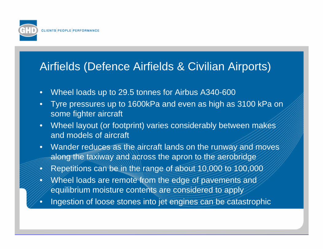
Airfields (Defence Airfields & Civilian Airports)
• Wheel loads up to 29.5 tonnes for Airbus A340-600• Tyre pressures up to 1600kPa and even as high as 3100 kPa on
some fighter aircraft• Wheel layout (or footprint) varies considerably between makes
and models of aircraft• Wander reduces as the aircraft lands on the runway and moves
along the taxiway and across the apron to the aerobridge• Repetitions can be in the range of about 10,000 to 100,000• Wheel loads are remote from the edge of pavements and
equilibrium moisture contents are considered to apply• Ingestion of loose stones into jet engines can be catastrophic


B-747 (open contact areas) B-737 (shaded contact areas)
SUPERIMPOSED FOOTPRINTS

Brief History of Thickness Design
Based on US Army Corps of Engineers experience for military airfields by R S Rollings (2003)
1940• B-17 and B-24 WW2 bombers had a single wheel on each main
undercarriage leg with wheel loads up to 18 tonnes• Larger bomber (B-29) proposed with dual wheels on each main leg and
70% heavier• Design used Westergaard's (1926) equations for a wheel load in the
centre of the slab – originally developed for roads• Plate load tests (0.76m dam) used to determine modulus of subgrade
reaction (k)
• Third point beam test used to measure flexural strength
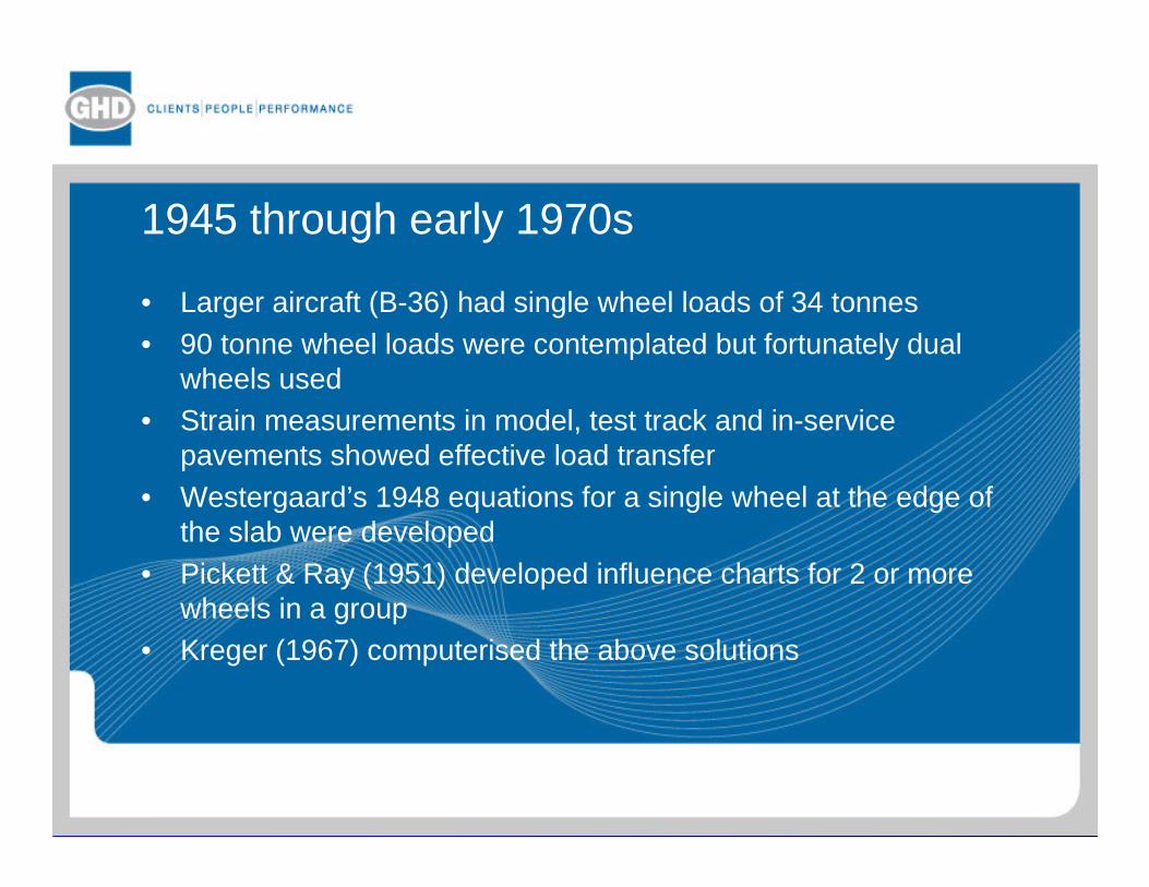
1945 through early 1970s
• Larger aircraft (B-36) had single wheel loads of 34 tonnes• 90 tonne wheel loads were contemplated but fortunately dual
wheels used• Strain measurements in model, test track and in-service
pavements showed effective load transfer• Westergaard’s 1948 equations for a single wheel at the edge of
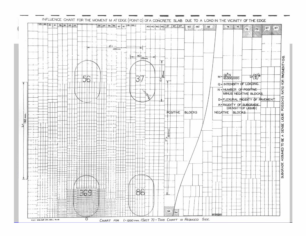
the slab were developed• Pickett & Ray (1951) developed influence charts for 2 or more
wheels in a group• Kreger (1967) computerised the above solutions
1970s
• Westergaard analysis approach showing its limitations• F-15E fighter had 2300 kPa tyre pressure and this was causing
damage to some pavements• The effect of complex 3 leg main gear on the commercial DC-10
and the military variant as an air refuelling tanker, the KC-10, was of concern
• The Westergaard models could not not handle stabilised layers
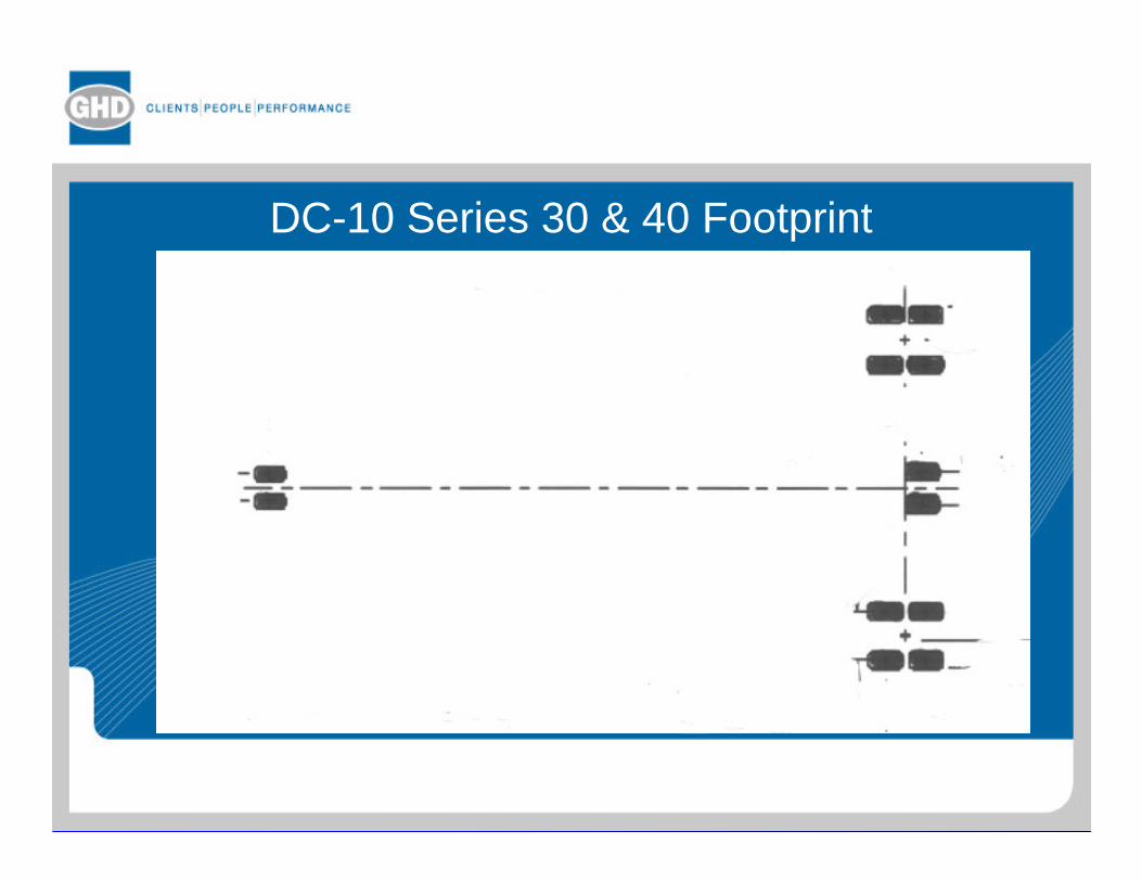
DC-10 Series 30 & 40 Footprint

1980s onwards
• 1980s Layered elastic design used for concrete pavements as an alternative to Westergaard
• Late 1990s state of the art Finite Element modelling of pavements was being developed but military operational pressures put this on hold.

Development of Design
• Theoretical methods have evolved over time but have lagged behind the needs of the designer
• Considerable experience has been gained from observations of test sections, successful and unsuccessful pavements and the practice has been adapted as needed
• The importance of accumulated engineering experience over long periods and judgement has been a major factor in improving designs
Federal Aviation Administration (FAA)
• FAA is the controlling authority for civil aviation in USA• Sets design standards for aircraft pavement design and other
matters
• Design using charts for individual aircraft with formulae for calculations are presented in Advisory Circulars (AC)
• AC 150/5320-6D Parts 1 to 5 plus amendments• These AC cover Airport Pavement Design & Evaluation• http://www.faa.gov/airports_airtraffic/airports/resources/advisory
_circulars/
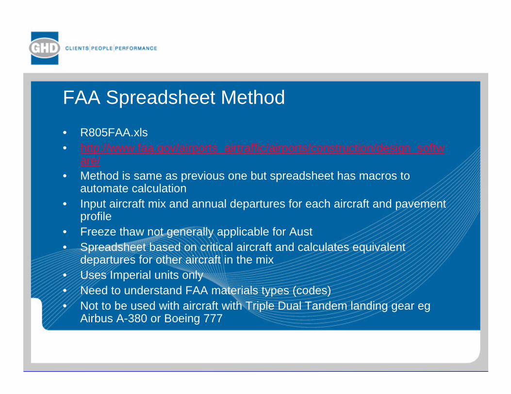
FAA Spreadsheet Method
• R805FAA.xls• http://www.faa.gov/airports_airtraffic/airports/construction/design_softw
are/• Method is same as previous one but spreadsheet has macros to
automate calculation• Input aircraft mix and annual departures for each aircraft and pavement
profile• Freeze thaw not generally applicable for Aust • Spreadsheet based on critical aircraft and calculates equivalent
departures for other aircraft in the mix• Uses Imperial units only• Need to understand FAA materials types (codes)• Not to be used with aircraft with Triple Dual Tandem landing gear eg
Airbus A-380 or Boeing 777
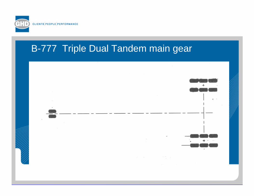
B-777 Triple Dual Tandem main gear

Layered Elastic Design Method
• Program LEDFAA• Can select either imperial or metric units• Mandatory to use this method with Triple Dual Tandem landing
gear such as A-380 or B-777 in aircraft mix• Covered by Chapter 7 of AC 150/5320-6D Change 3• No user manual but drop down help menus
http://www.faa.gov/airports_airtraffic/airports/construction/design_software/
Finite Element Method
• Proposed FAA method not yet approved for design use• Program FAARFIELD Version 1.302 made available as a Beta
version for evaluation or research• A number of extensive reports are available on the software and
its development
http://www.faa.gov/airports_airtraffic/airports/construction/design_software/

Program CONCC
• Originally used on mainframe computer, then on PC• Only available as compiled Fortran• Original code now lost• Uses “fixed format” Fortran – right adjusted, integers & floating
point formats must be adhered to• Careful attention to input data• Determines thickness for given concrete strength & k value• Can consider 10 aircraft in the traffic mix• Simulates “influence chart” method within 10% for 4 wheel gear• Each leg is limited to 8 wheels• Antonov An-124 (10 wheels per leg) cannot be directly
simulated

Brisbane Airport
Pavements comprised the following• 400mm plain concrete• 150mm crushed rock base (well graded to prevent pumping)• 1500mm sand• Subgrade of mangrove clay
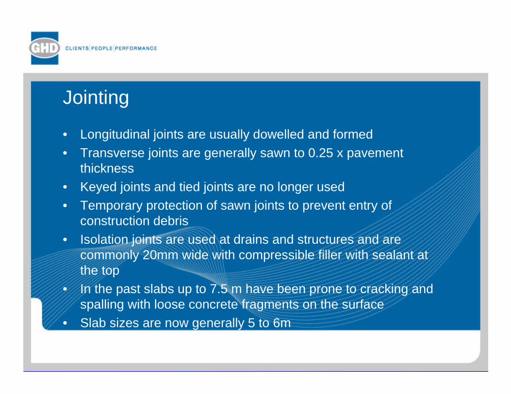
Jointing
• Longitudinal joints are usually dowelled and formed• Transverse joints are generally sawn to 0.25 x pavement
thickness• Keyed joints and tied joints are no longer used• Temporary protection of sawn joints to prevent entry of
construction debris• Isolation joints are used at drains and structures and are
commonly 20mm wide with compressible filler with sealant at the top
• In the past slabs up to 7.5 m have been prone to cracking and spalling with loose concrete fragments on the surface
• Slab sizes are now generally 5 to 6m
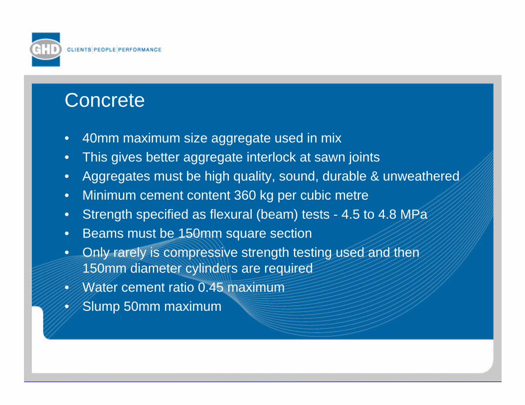
Concrete
• 40mm maximum size aggregate used in mix• This gives better aggregate interlock at sawn joints• Aggregates must be high quality, sound, durable & unweathered• Minimum cement content 360 kg per cubic metre• Strength specified as flexural (beam) tests - 4.5 to 4.8 MPa• Beams must be 150mm square section• Only rarely is compressive strength testing used and then
150mm diameter cylinders are required• Water cement ratio 0.45 maximum• Slump 50mm maximum

Joint Sealing
• Taxiways and Runway ends may have narrow unsealed joints• On Aprons, where surface activity is high, joints are more likely
to be sealed• Initial saw cut widened to about 10mm for the sealant• Sealants are silicone, polysulphide or polyurethane• Self expanding cork is no longer used

Reinforcement & Dowels
Reinforcement• Pavements are predominantly plain (unreinforced) concrete• Mesh reinforcement is used in odd shaped (outside 1.25 : 1
ratio) or where pits or footings for light towers etc occur in apanel or where mismatched joints occur
• For 400mm thick slab – SL 82 at 130mm coverDowels• For 400mm thick slab – R36 dowels at 375mm ctrs and 500mm
long

Spalling at grated drain – inadequate isolation joint
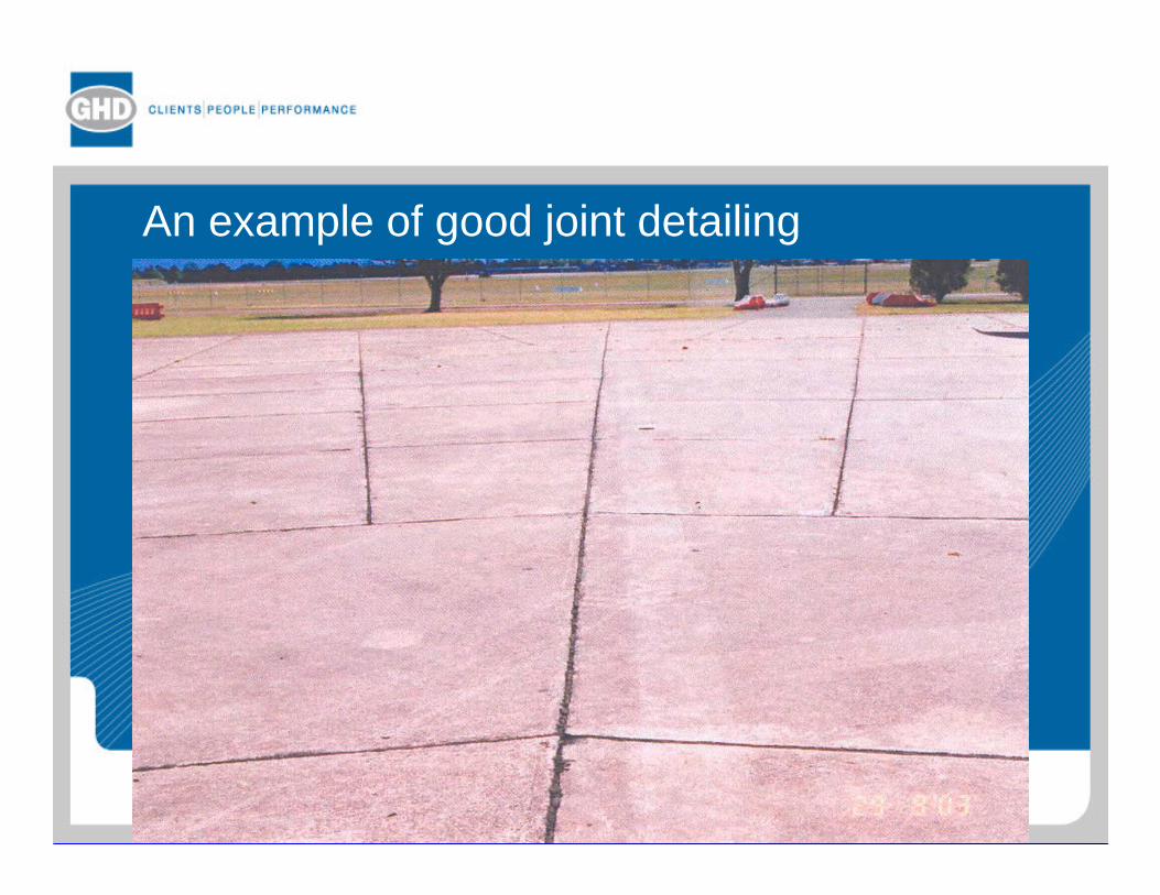
An example of good joint detailing


PCA & AIRpave Program
• Portland Cement Assoc (PCA) in USA has transferred rights to PCA Eng Bulletin EB050P Design of Airport Pavement by Robert Packard (1973, reprinted 1995) to American Concrete Pavement Assoc (ACPA) – www.pavement.com
• Program AIRpave 2000 Version 1.2 (2001) is available from ACPA – it is understood to be an update of the 1968 PCA program


![Luftwaffe Airfields 1935-45 Austria (1937 Borders) - Austria [1937 Borders].pdf · Luftwaffe Airfields 1935-45 Airfields Austria (1937 borders) Introduction Preface The Germans marched](https://static.documents.pub/doc/80x56/5b67ba067f8b9a68538b8c0b/luftwaffe-airfields-1935-45-austria-1937-borders-austria-1937-borderspdf.jpg)


