07/10/2009 Concurrent Design of Embedded Control Software 1 Concurrent Design of Embedded Control Software Third International Workshop on Multi-Paradigm Modeling MPM`09, 06-10-2009 Marcel Groothuis, Jan Broenink University of Twente, The Netherlands Raymond Frijns, Jeroen Voeten Eindhoven University of Technology, The Netherlands
Transcript
07/10/2009 Concurrent Design of Embedded Control Software
1
Concurrent Design ofEmbedded Control SoftwareThird International Workshop on Multi-Paradigm ModelingMPM`09, 06-10-2009
Marcel Groothuis, Jan BroeninkUniversity of Twente, The Netherlands
Raymond Frijns, Jeroen VoetenEindhoven University of Technology, The Netherlands
Concurrent Design of Embedded Control Software 2
Contents
� Introduction� Mechatronic systems design challenges� Embedded Control Systems software
� Model-driven Design Methodology
� Case study
� Results & Conclusions
Concurrent Design of Embedded Control Software 3
Introduction – Mechatronics challenges
� Developing Reliable and Robust Embedded Control Software for mechatronic applications is too costly and too time consuming.
� Reasons:� Complexity, Heterogeneity, Lack of Predictability, Late Integration
� Approaches to tackle the problem� Concurrent Engineering, Model Driven Design, Early Integration
ContinuousTime
Control
Discrete Event
Control
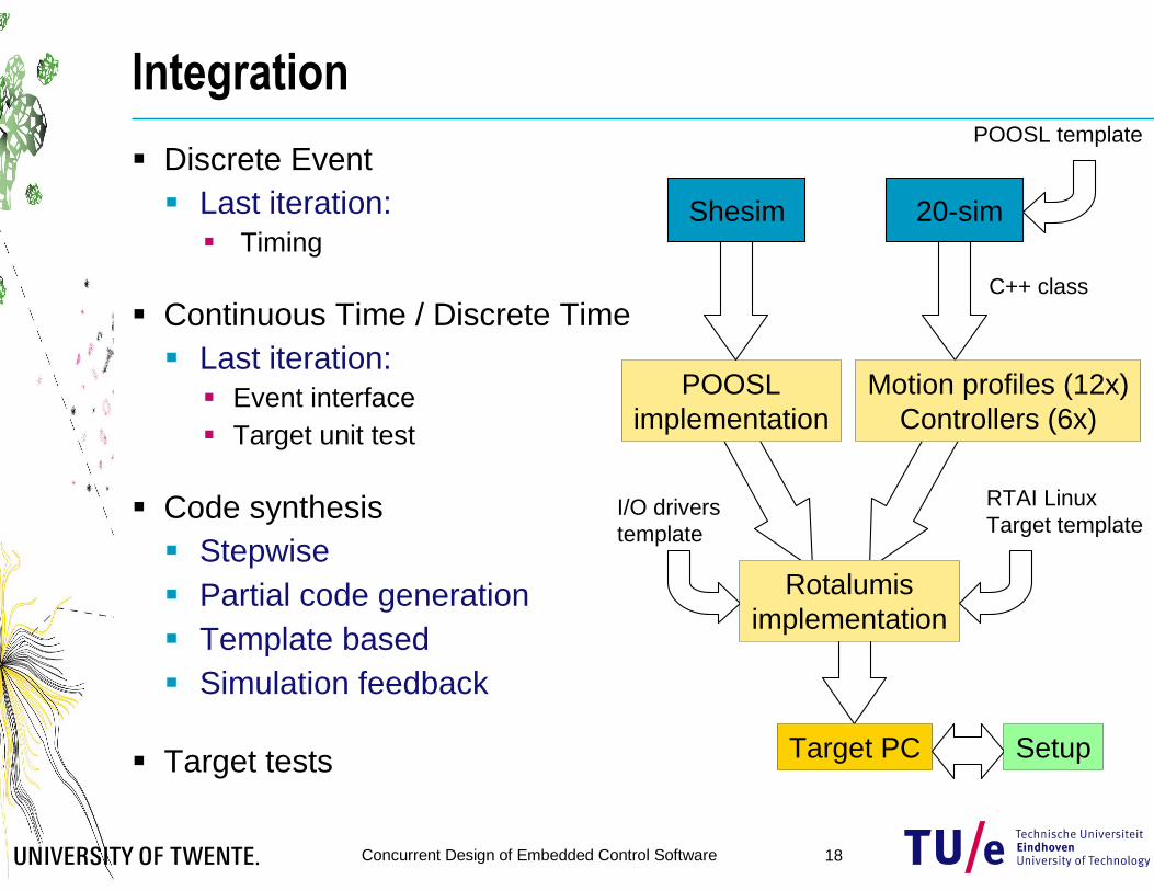
Integration
ContinuousTime
Control
Integration
ContinuousTime
Control
DiscreteEvent
Control
Integration
Sequentialdesign process (a)
Concurrent design process (b)
Trade-off between concurrency efficiency and integration efficiency (d)
� Essential Properties Embedded Control Software� Dynamic behavior of the physical system essential for SW� Real-time constraints with low-latency requirement� Dependability: Safety, Reliability
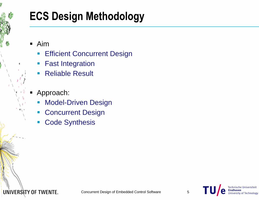
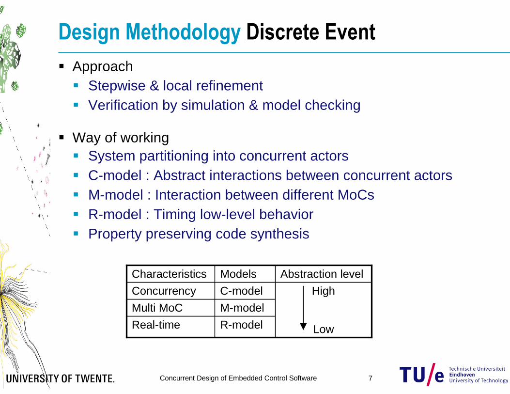
� Approach� Stepwise & local refinement� Verification by simulation & model checking
� Way of working� System partitioning into concurrent actors� C-model : Abstract interactions between concurrent actors� M-model : Interaction between different MoCs� R-model : Timing low-level behavior� Property preserving code synthesis
R-modelReal-time
M-modelMulti MoC
High
Low
C-modelConcurrency
Abstraction levelModelsCharacteristics
Concurrent Design of Embedded Control Software 8
Design Methodology Continuous Time
� Approach� Stepwise & local refinement
� From model towards controller code
� Verification by simulation
� Way of Working
� Model & UnderstandPhysical system dynamics
� Simplify model, derive the control laws
� Interfaces & target� Add non-ideal components (AD, DA, PC)
� Dependability: Safety, Reliability, …
� Integrate control laws into ES� Scaling/conversion factors� Via local refinement:
� Integration efficiency analysis� Comparison with other test cases on the same setup
Concurrent Design of Embedded Control Software 10
Case Study Production cell
Production cell demonstrator� Based on:
Stork Plastics Molding machine
� Architecture� CPU (ECS) + FPGA (digital I/O)� Distributed Control possible
� 6 Production Cell units� Action in the production process
� Molding, Extraction,Transportation, Storage
� Synchronize with neighbors� Deadlock possible on > 7 blocks
CPU +
FPGA
Motor 150W
Gearhead 43:1
Encoder
Motor 150W
Gearhead 43:1
Encoder
Al
Extraction unit
Molderdoor
Feederunit
Feeder belt
Extraction belt
Rotation
unit
Motor 70W
Gearhead 18:1
Encoder
Magnet
Sensor
Extractionbuffer
Molderunit
Block movement direction
Embedded PC
Concurrent Design of Embedded Control Software 11
Case Study Production cell
� Embedded Control System Software Design� Jointly
� Specs, partitioning, interfaces
� Concurrently� SW partitions
� Jointly� SW integration & testing
ContinuousTime
Control
DiscreteEvent
Control
IntegrationDes
ign
Tim
e
Model-driven concurrent design process
1
3
2
Specs
User
interface
Supervisory
control &
Interaction
Sequence
control
Loop control
Safety layer
Concurrent Design of Embedded Control Software 12
Case Study Partitioning & Hierarchy
� Embedded Software� Discrete Event partition� Continuous/Discrete Time partition
� Based on� Top level system model� Production Cell Units (PCUs)
� Layered Software structure
� Interface
User
interface
Supervisory
control &
Interaction
Sequence
control
Loop control
Safety layer
CTCT/DTDE
CPU +
FPGA
Motor 150W
Gearhead 43:1
Encoder
Motor 150W
Gearhead 43:1
Encoder
Al
Extraction unit
Molderdoor
Feederunit
Feeder belt
Extraction belt
Rotation
unit
Motor 70W
Gearhead 18:1
Encoder
Motor 150W
Gearhead 15:1
Encoder
Magnet
Motor 150W
Gearhead 15:1
Encoder
Sensor
Extractionbuffer
Molderunit
Block movement direction
Embedded PC
Interface definitions
Concurrent Design of Embedded Control Software 13
Discrete Event Software Design
� Modeling tools : SHESim/Rotalumis� POOSL: Parallel Object-Oriented Specification Language� SHESim: Graphical tool for model construction and simulation� Rotalumis: Fast execution engine built in C++
� C-model : handshake diagram formalized in POOSL model� Partitions design into a set of concurrent actors� Actors synchronize action by a handshake sequence� Models untimed abstract interactions between actors
Concurrent Design of Embedded Control Software 14
Discrete Event Software Design
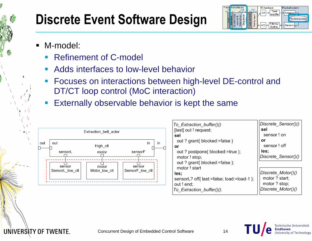
� M-model:� Refinement of C-model� Adds interfaces to low-level behavior� Focuses on interactions between high-level DE-control and
DT/CT loop control (MoC interaction)� Externally observable behavior is kept the same
Concurrent Design of Embedded Control Software 15
Discrete Event Software Design
� R-model: � Refinement of M-model� Adds low-level behavior � Both DT and DE behavior � Adds timing� Again, externally observable
functional behavior is kept the same
� Automatic code synthesis:� Automatic mapping to target platform� Property-preserving code generation� Building blocks with common interface � Mathematically proven timing relation
between model and implementation
Continuous()()
[ curstate = prestate ]
curstate := sensor Read;
delay 0.01;
Continuous()().
Discrete()()
sel
[ (curstate) & (prestate=false) ]
sensor ! on { prestate := curstate }
or
[ (prestate) & (curstate=false) ]
sensor ! off { prestate := curstate }
les;
Discrete()().
Concurrent Design of Embedded Control Software 16
Continuous Time Software Design
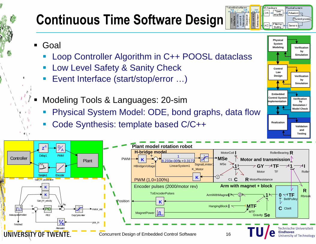
� Goal� Loop Controller Algorithm in C++ POOSL dataclass� Low Level Safety & Sanity Check� Event Interface (start/stop/error …)
� Modeling Tools & Languages: 20-sim� Physical System Model: ODE, bond graphs, data flow� Code Synthesis: template based C/C++
Sample1 Encoder
Z-1
Delay1
PlantController
AD
PWM
PhysicalSystem
Modeling
ControlLaw
Design
EmbeddedControl SystemImplementation
Verificationby
Simulation / Model Check
Realization
Validationand
Testing
Verificationby
Simulation
Verificationby
Simulation
PhysicalSystem
Modeling
ControlLaw
Design
EmbeddedControl SystemImplementation
Verificationby
Simulation / Model Check
Realization
Validationand
Testing
Verificationby
Simulation
Verificationby
Simulation
PhysicalSystem
Modeling
ControlLaw
Design
EmbeddedControl SystemImplementation
Verificationby
Simulation / Model Check
Realization
Validationand
Testing
Verificationby
Simulation
Verificationby
Simulation
PhysicalSystem
Modeling
ControlLaw
Design
EmbeddedControl SystemImplementation
Verificationby
Simulation / Model Check
Realization
Validationand
Testing
Verificationby
Simulation
Verificationby
Simulation
pos_infinished
motor_out
MotionprofileFWBW
K1
Attenuate1
K
Gain_FF_velocity
K
Gain_FF_acceleration
PIDPID2 DutyCyleLimiter
H-bridge model
PWM (1.0=100%)
Encoder pulses (2000/motor rev) Arm with magnet + block
Plant model rotation robot
Motor and transmission
Position
PWM KHBridgeVoltage
K
K_Motor
18.233e-005s +0.3172
LinearSystem1 SignalLimiter1
K
ToEncoderPulses IArmWithMagnet
IRoller
RRollerBearing
TFTF
TFBeltPulley
C Cbelt
0
GYMotor
CC1
IMotorCoil
RRbreak
1
MSeMSe 1
R MotorResistance
1
IHangingBlock MTFMTF
p
MagnetPower SeGravity
f
Concurrent Design of Embedded Control Software 17
Continuous Time Software DesignControlled Motion Rotation Robot
0
0.1
0.2
0.3
0.4
Ref Position {m}
-5
0
5 Motor current {A}
-500
0
500 Rotation velocity {rad/s}
-0.5
0
0.5 PWM Output {x100%)
0
1
2
3 Real Pos {rad}
-0.0005
0
0.0005 Error {m}
0
0.5
1
1.5Forward Finished
0 0.5 1 1.5 2time {s}
0
0.5
1
1.5Backward Finished
class Controller_Rotation: public PooslDataClass{ /* the model functions */