44
OPERATING MANUAL ba75927e05 12/2017 Cond 7110 CONDUCTIVITY METER
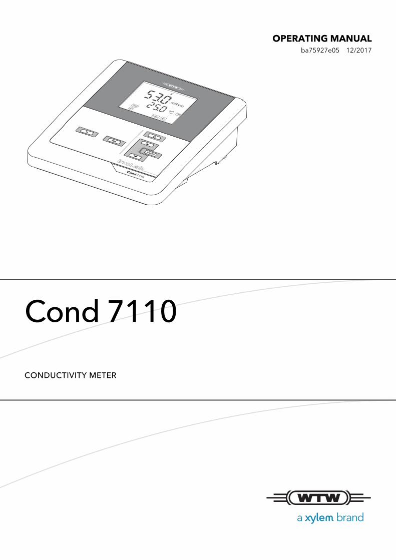
OPERATING MANUALba75927e05 12/2017
Cond 7110
CONDUCTIVITY METER
Cond 7110
Copyright © 2017, Xylem Analytics Germany GmbHPrinted in Germany.
2 ba75927e05 12/2017

Cond 7110 - Contents
Cond 7110 Contents
1 Overview . . . . . . . . . . . . . . . . . . . . . . . . . . . . . . . . . 7
1.1 Cond 7110 meter. . . . . . . . . . . . . . . . . . . . . . . . . . . . . . . . . . . . . . . . 7
1.2 Sensors . . . . . . . . . . . . . . . . . . . . . . . . . . . . . . . . . . . . . . . . . . . . . . . 7
2 Safety. . . . . . . . . . . . . . . . . . . . . . . . . . . . . . . . . . . . 8
2.1 Safety information . . . . . . . . . . . . . . . . . . . . . . . . . . . . . . . . . . . . . . . 82.1.1 Safety information in the operating manual. . . . . . . . . . . . . . . . 82.1.2 Safety signs on the meter . . . . . . . . . . . . . . . . . . . . . . . . . . . . . 82.1.3 Further documents providing safety information . . . . . . . . . . . . 8
2.2 Safe operation . . . . . . . . . . . . . . . . . . . . . . . . . . . . . . . . . . . . . . . . . . 92.2.1 Authorized use . . . . . . . . . . . . . . . . . . . . . . . . . . . . . . . . . . . . . 92.2.2 Requirements for safe operation. . . . . . . . . . . . . . . . . . . . . . . . 92.2.3 Unauthorized use . . . . . . . . . . . . . . . . . . . . . . . . . . . . . . . . . . . 9
3 Commissioning. . . . . . . . . . . . . . . . . . . . . . . . . . . 10
3.1 Scope of delivery . . . . . . . . . . . . . . . . . . . . . . . . . . . . . . . . . . . . . . . 10
3.2 Power supply . . . . . . . . . . . . . . . . . . . . . . . . . . . . . . . . . . . . . . . . . . 10
3.3 Initial commissioning . . . . . . . . . . . . . . . . . . . . . . . . . . . . . . . . . . . . 103.3.1 Inserting the batteries . . . . . . . . . . . . . . . . . . . . . . . . . . . . . . . 103.3.2 Connecting the power pack. . . . . . . . . . . . . . . . . . . . . . . . . . . 113.3.3 Mounting the stand . . . . . . . . . . . . . . . . . . . . . . . . . . . . . . . . . 12
4 Operation. . . . . . . . . . . . . . . . . . . . . . . . . . . . . . . . 13
4.1 General operating principles . . . . . . . . . . . . . . . . . . . . . . . . . . . . . . 134.1.1 Keypad . . . . . . . . . . . . . . . . . . . . . . . . . . . . . . . . . . . . . . . . . . 134.1.2 Display . . . . . . . . . . . . . . . . . . . . . . . . . . . . . . . . . . . . . . . . . . 14
ba75927e05 12/2017 3
Contents Cond 7110
4.1.3 Status information . . . . . . . . . . . . . . . . . . . . . . . . . . . . . . . . . 144.1.4 Socket field . . . . . . . . . . . . . . . . . . . . . . . . . . . . . . . . . . . . . . 15
4.2 Switching on the meter. . . . . . . . . . . . . . . . . . . . . . . . . . . . . . . . . . 15
4.3 Switching off the meter. . . . . . . . . . . . . . . . . . . . . . . . . . . . . . . . . . 15
4.4 Navigation . . . . . . . . . . . . . . . . . . . . . . . . . . . . . . . . . . . . . . . . . . . 164.4.1 Operating modes . . . . . . . . . . . . . . . . . . . . . . . . . . . . . . . . . . 164.4.2 Measuring mode (measured value display) . . . . . . . . . . . . . . 164.4.3 Setting mode . . . . . . . . . . . . . . . . . . . . . . . . . . . . . . . . . . . . . 16
5 Conductivity . . . . . . . . . . . . . . . . . . . . . . . . . . . . . 17
5.1 Measuring. . . . . . . . . . . . . . . . . . . . . . . . . . . . . . . . . . . . . . . . . . . . 175.1.1 Measuring the conductivity . . . . . . . . . . . . . . . . . . . . . . . . . . 175.1.2 Measuring the temperature . . . . . . . . . . . . . . . . . . . . . . . . . . 18
5.2 Calibration . . . . . . . . . . . . . . . . . . . . . . . . . . . . . . . . . . . . . . . . . . . 195.2.1 Why calibrate? . . . . . . . . . . . . . . . . . . . . . . . . . . . . . . . . . . . . 195.2.2 When to calibrate? . . . . . . . . . . . . . . . . . . . . . . . . . . . . . . . . . 195.2.3 Determining the cell constant (calibration in control standard) 195.2.4 Using the last calibrated cell constant . . . . . . . . . . . . . . . . . . 205.2.5 Setting the cell constant manually . . . . . . . . . . . . . . . . . . . . . 215.2.6 Calibration data . . . . . . . . . . . . . . . . . . . . . . . . . . . . . . . . . . . 22
6 Settings . . . . . . . . . . . . . . . . . . . . . . . . . . . . . . . . . 24
6.1 Measurement settings (conductivity) . . . . . . . . . . . . . . . . . . . . . . . 246.1.1 Changing the settings for conductivity measurements . . . . . 246.1.2 Cleaning interval . . . . . . . . . . . . . . . . . . . . . . . . . . . . . . . . . . 256.1.3 Selecting the temperature compensation . . . . . . . . . . . . . . . 256.1.4 Setting the TDS factor . . . . . . . . . . . . . . . . . . . . . . . . . . . . . . 26
6.2 Sensor-independent settings . . . . . . . . . . . . . . . . . . . . . . . . . . . . . 276.2.1 Changing the sensor-independent settings . . . . . . . . . . . . . . 276.2.2 Energy saving (battery operation) . . . . . . . . . . . . . . . . . . . . . 27
7 Reset . . . . . . . . . . . . . . . . . . . . . . . . . . . . . . . . . . . 28
7.1 Erasing the calibration values . . . . . . . . . . . . . . . . . . . . . . . . . . . . 28
7.2 Resetting the measurement and system settings . . . . . . . . . . . . . 28
4 ba75927e05 12/2017
Cond 7110 Contents
8 Maintenance, cleaning, disposal . . . . . . . . . . . . . 30
8.1 Maintenance. . . . . . . . . . . . . . . . . . . . . . . . . . . . . . . . . . . . . . . . . . 308.1.1 General maintenance activities . . . . . . . . . . . . . . . . . . . . . . . 308.1.2 Replacing the batteries . . . . . . . . . . . . . . . . . . . . . . . . . . . . . 30
8.2 Cleaning . . . . . . . . . . . . . . . . . . . . . . . . . . . . . . . . . . . . . . . . . . . . . 31
8.3 Packing. . . . . . . . . . . . . . . . . . . . . . . . . . . . . . . . . . . . . . . . . . . . . . 31
8.4 Disposal . . . . . . . . . . . . . . . . . . . . . . . . . . . . . . . . . . . . . . . . . . . . . 31
9 What to do if... . . . . . . . . . . . . . . . . . . . . . . . . . . . . 32
9.1 Conductivity . . . . . . . . . . . . . . . . . . . . . . . . . . . . . . . . . . . . . . . . . . 329.1.1 Error message E3 . . . . . . . . . . . . . . . . . . . . . . . . . . . . . . . . . 329.1.2 Error message OFL, UFL. . . . . . . . . . . . . . . . . . . . . . . . . . . . 32
9.2 General information . . . . . . . . . . . . . . . . . . . . . . . . . . . . . . . . . . . . 329.2.1 [LoBat] Display. . . . . . . . . . . . . . . . . . . . . . . . . . . . . . . . . . . . 329.2.2 Instrument does not react to keystroke . . . . . . . . . . . . . . . . . 339.2.3 Displaying the software version (meter). . . . . . . . . . . . . . . . . 33
10 Technical data . . . . . . . . . . . . . . . . . . . . . . . . . . . . 34
10.1 Measuring ranges, resolution, accuracy. . . . . . . . . . . . . . . . . . . . . 3410.1.1 Measuring ranges, resolution. . . . . . . . . . . . . . . . . . . . . . . . . 3410.1.2 Cell constants . . . . . . . . . . . . . . . . . . . . . . . . . . . . . . . . . . . . 3510.1.3 Reference temperature . . . . . . . . . . . . . . . . . . . . . . . . . . . . . 3510.1.4 Accuracy (± 1 digit) . . . . . . . . . . . . . . . . . . . . . . . . . . . . . . . . 35
10.2 General data. . . . . . . . . . . . . . . . . . . . . . . . . . . . . . . . . . . . . . . . . . 36
11 Glossary. . . . . . . . . . . . . . . . . . . . . . . . . . . . . . . . . 38
11.1 Conductivity . . . . . . . . . . . . . . . . . . . . . . . . . . . . . . . . . . . . . . . . . . 38
11.2 General information . . . . . . . . . . . . . . . . . . . . . . . . . . . . . . . . . . . . 39
12 Index. . . . . . . . . . . . . . . . . . . . . . . . . . . . . . . . . . . . 41
ba75927e05 12/2017 5
Contents Cond 7110
6 ba75927e05 12/2017
Cond 7110 Overview
1 Overview
1.1 Cond 7110 meter
The Cond 7110 compact digital precision meter enables you to perform conductivity measurements quickly and reliably.
The Cond 7110 provides the maximum degree of operating comfort, reliability and measuring certainty for all applications.
1.2 Sensors
A measuring system ready to measure consists of the Cond 7110 meter and a suitable sensor.
Suitable sensors are conductivity measuring cells.
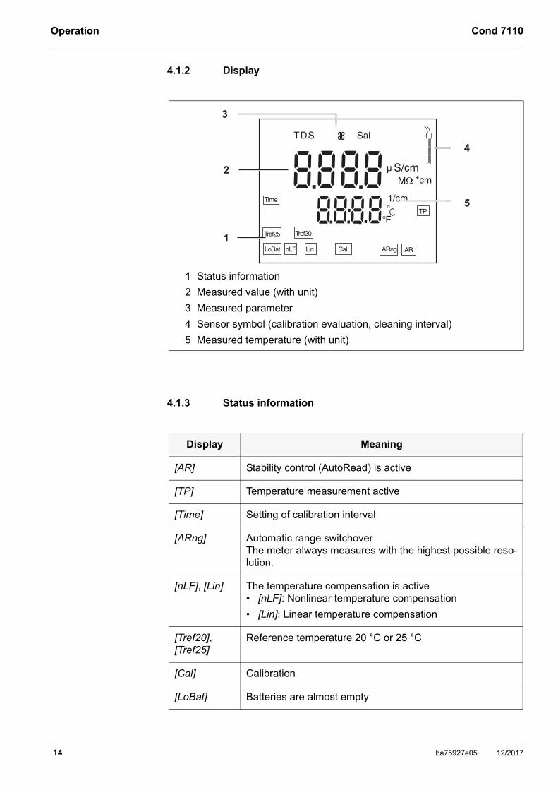
1 Keypad
2 Display
3 Socket field
1
2
3
Information on available sensors is given on the Internet and in the WTW catalog, "Laboratory and field instrumentation".
ba75927e05 12/2017 7
Safety Cond 7110
2 Safety
2.1 Safety information
2.1.1 Safety information in the operating manual
This operating manual provides important information on the safe operation of the meter. Read this operating manual thoroughly and make yourself familiar with the meter before putting it into operation or working with it. The operating manual must be kept in the vicinity of the meter so you can always find the infor-mation you need.
Important safety instructions are highlighted in this operating manual. They are indicated by the warning symbol (triangle) in the left column. The signal word (e.g. "CAUTION") indicates the level of danger:
NOTEindicates a possibly dangerous situation where goods might be damaged if the actions mentioned are not taken.
2.1.2 Safety signs on the meter
Note all labels, information signs and safety symbols on the meter and in the battery compartment. A warning symbol (triangle) without text refers to safety information in this operating manual.
2.1.3 Further documents providing safety information
The following documents provide additional information, which you should observe for your safety when working with the measuring system:
• Operating manuals of sensors and other accessories
• Safety datasheets of calibration or maintenance accessories (such as buffer solutions, electrolyte solutions, etc.)
WARNING
indicates a possibly dangerous situation that can lead to serious (irreversible) injury or death if the safety instruction is not followed.
CAUTION
indicates a possibly dangerous situation that can lead to slight (reversible) injury if the safety instruction is not followed.
8 ba75927e05 12/2017
Cond 7110 Safety
2.2 Safe operation
2.2.1 Authorized use
This meter is authorized exclusively for conductivity measurements in the labo-ratory.
Only the operation and running of the meter according to the instructions and technical specifications given in this operating manual is authorized (see section 10 TECHNICAL DATA, page 34).
Any other use is considered unauthorized.
2.2.2 Requirements for safe operation
Note the following points for safe operation:
• The meter may only be operated according to the authorized use specified above.
• The meter may only be supplied with power by the energy sources mentioned in this operating manual.
• The meter may only be operated under the environmental conditions mentioned in this operating manual.
• The meter may only be opened if this is explicitly described in this operating manual (example: Inserting the batteries).
2.2.3 Unauthorized use
The meter must not be put into operation if:
• it is visibly damaged (e.g. after being transported)
• it was stored under adverse conditions for a lengthy period of time (storing conditions, see section 10 TECHNICAL DATA, page 34).
ba75927e05 12/2017 9

Commissioning Cond 7110
3 Commissioning
3.1 Scope of delivery
• Cond 7110 meter
• 4 batteries 1.5 V Mignon type AA
• Power pack
• Stand
• Stand holder
• Short instructions
• Detailed operating manual (4 languages)
• CD-ROM with detailed operating manual
3.2 Power supply
The Cond 7110 is supplied with power in the following ways:
• Mains operation with the supplied power pack.
• Battery operation (4 x alkaline manganese batteries, type AA)
3.3 Initial commissioning
Perform the following activities:
• Insert the supplied batteries
• Connect the power pack (mains operation)
• Mount the stand
• Switch on the meter
(see section 4.2 SWITCHING ON THE METER, page 15)
3.3.1 Inserting the batteries
You can operate the meter either with normal batteries or with rechargeable batteries (Ni-MH). In order to charge the batteries, an external charging device is required.
10 ba75927e05 12/2017
Cond 7110 Commissioning
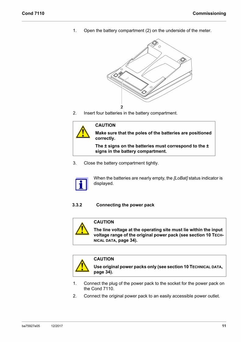
1. Open the battery compartment (2) on the underside of the meter.
2. Insert four batteries in the battery compartment.
3. Close the battery compartment tightly.
3.3.2 Connecting the power pack
1. Connect the plug of the power pack to the socket for the power pack on the Cond 7110.
2. Connect the original power pack to an easily accessible power outlet.
CAUTION
Make sure that the poles of the batteries are positioned correctly.
The ± signs on the batteries must correspond to the ± signs in the battery compartment.
When the batteries are nearly empty, the [LoBat] status indicator is displayed.
2
CAUTION
The line voltage at the operating site must lie within the input voltage range of the original power pack (see section 10 TECH-NICAL DATA, page 34).
CAUTION
Use original power packs only (see section 10 TECHNICAL DATA, page 34).
ba75927e05 12/2017 11
Commissioning Cond 7110
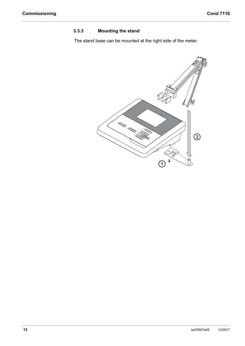
3.3.3 Mounting the stand
The stand base can be mounted at the right side of the meter.
1
2
12 ba75927e05 12/2017
Cond 7110 Operation
4 Operation
4.1 General operating principles
This section contains basic information on the operation of the Cond 7110.
4.1.1 Keypad
In this operating manual, keys are indicated by brackets <..> .
The key symbol (e.g. <MENU/OK>) generally indicates a short keystroke (under 2 sec) in this operating manual. A long keystroke (approx. 2 sec) is indi-cated by the underscore behind the key symbol (e.g. <MENU/OK_>).
Key Symbol Meaning
<On/Off> <On/Off_>
Switches the meter on or offResets calibration data
<MODE> <MODE_>
Selects the measured parameter Opens the measurement settings
<CAL> <CAL_>
Calls up the calibration procedureDisplays the calibration data
<><> <__><__>
Increments, decrements valuesIncrements, decrements values continu-ously
<MENU/OK> <MENU/OK_>
Confirms entriesOpens the menu for system settings
ba75927e05 12/2017 13
Operation Cond 7110
4.1.2 Display
4.1.3 Status information
1 Status information
2 Measured value (with unit)
3 Measured parameter
4 Sensor symbol (calibration evaluation, cleaning interval)
5 Measured temperature (with unit)
Time 1/cm
88 88
8 888°F
C°
TDS Sal
S/cmM
LoBat
Tref25 Tref20
ARngCalnLF AR
TP
µ
3
2
4
5
1
*cm
Lin
Display Meaning
[AR] Stability control (AutoRead) is active
[TP] Temperature measurement active
[Time] Setting of calibration interval
[ARng] Automatic range switchoverThe meter always measures with the highest possible reso-lution.
[nLF], [Lin] The temperature compensation is active• [nLF]: Nonlinear temperature compensation
• [Lin]: Linear temperature compensation
[Tref20], [Tref25]
Reference temperature 20 °C or 25 °C
[Cal] Calibration
[LoBat] Batteries are almost empty
14 ba75927e05 12/2017

Cond 7110 Operation
4.1.4 Socket field
4.2 Switching on the meter
1. Switch on the meter with <On/Off>.The meter performs a self-test.
2. Connect the sensor.The meter is ready to measure.
4.3 Switching off the meter
1. Switch off the meter with <On/Off>.The meter is switched off.
1 Conductivity measuring cell
2 Power pack
3 Service interface
1 2 3
052
035C°
S/cmm
nLF
TP
Tref25
ARARng
When the meter is powered by the batteries, it switches itself off automatically after an adjustable interval to save the bat-teries (see section Automatic switch-off function, page 27 ).
ba75927e05 12/2017 15

Operation Cond 7110
4.4 Navigation
4.4.1 Operating modes
The meter has the following operating modes:
4.4.2 Measuring mode (measured value display)
The following functions are available in the measuring mode (measured value display):
• To change the indication on the measuring screen (e.g. ϰ <-> Sal <-> TDS <-> Resistance), press <MODE>.
• To open the measurement settings, press <MODE_> (long pressure).
• To open the system settings, press <ENTER__> (long pressure).
4.4.3 Setting mode
The following functions are available in the setting mode:
• To change the current setting, press <><>.
• Confirm the setting with <ENTER>.
The next setting is displayed.
The settings are stored.
• Press <MODE> to exit the setting mode.
Operating mode Description
Measuring The measurement data of the connected sensor are shown in the measured value display
Calibration The course of a calibration with calibration informa-tion, functions and settings is displayed
Setting A setting is displayed.
When the last setting is confirmed, the setting menu is auto-matically quit.
16 ba75927e05 12/2017
Cond 7110 Conductivity
5 Conductivity
5.1 Measuring
5.1.1 Measuring the conductivity
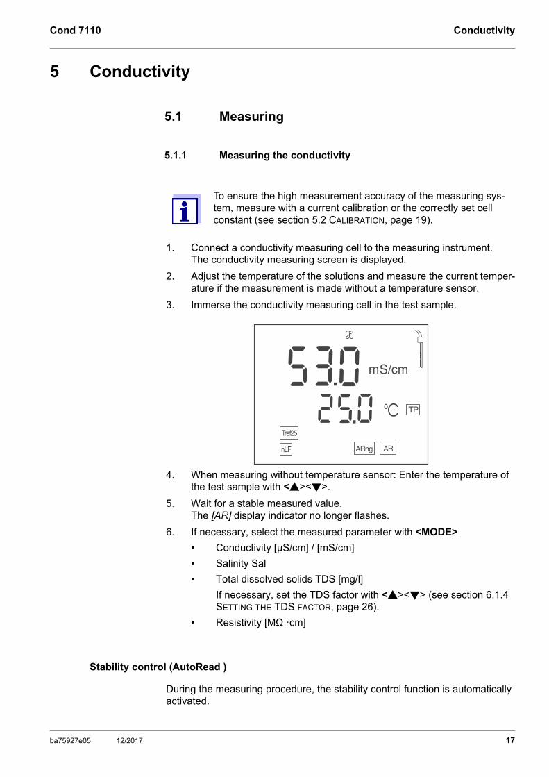
1. Connect a conductivity measuring cell to the measuring instrument.The conductivity measuring screen is displayed.
2. Adjust the temperature of the solutions and measure the current temper-ature if the measurement is made without a temperature sensor.
3. Immerse the conductivity measuring cell in the test sample.
4. When measuring without temperature sensor: Enter the temperature of the test sample with <><>.
5. Wait for a stable measured value.The [AR] display indicator no longer flashes.
6. If necessary, select the measured parameter with <MODE>.
• Conductivity [µS/cm] / [mS/cm]
• Salinity Sal
• Total dissolved solids TDS [mg/l]
If necessary, set the TDS factor with <><> (see section 6.1.4 SETTING THE TDS FACTOR, page 26).
• Resistivity [MΩ ·cm]
Stability control (AutoRead )
During the measuring procedure, the stability control function is automatically activated.
To ensure the high measurement accuracy of the measuring sys-tem, measure with a current calibration or the correctly set cell constant (see section 5.2 CALIBRATION, page 19).
052
035C°
S/cmm
nLF
TP
Tref25
ARARng
ba75927e05 12/2017 17

Conductivity Cond 7110
The stability control function (AutoRead) continually checks the stability of the measured values in the monitored time interval. The stability has a consider-able impact on the reproducibility of measured values. The [AR] display indi-cator flashes until a stable value is measured.
Stability criteria (AutoRead )
5.1.2 Measuring the temperature
The temperature measurement is absolutely essential for a reproducible conductivity measurement.
You have the following options to measure the temperature:
• Automatic measurement of the temperature with the temperature sensor (NTC30 or Pt1000) integrated in the sensor.
• Manual determination and input of the temperature.
The measuring instrument recognizes whether a suitable sensor is connected and automatically switches on the temperature measurement.
Which type of temperature measurement is active is indicated by the tempera-ture display and the [TP] status indicator:
If you wish to measure (or calibrate) without temperature sensor, proceed as follows:
1. Measure the current temperature of the test sample.
2. Set the temperature value with <><>.
Measured parameter
Time inter-val Stability in the time interval
Conductivity ϰ 10 seconds ∆ : better than 1.0 % of measured value
Temperature 15 seconds ∆ : Better than 0.5 ° C
Tempera-ture sensor
Resolution of the temp. dis-
playStatus indica-
torTemp. measure-
ment
yes 0.1 °C [TP] Automatic with tem-perature sensor
- 1 °C - Manual
18 ba75927e05 12/2017
Cond 7110 Conductivity
5.2 Calibration
5.2.1 Why calibrate?
Aging slightly changes the cell constant, e. g. due to coatings. As a result, an inexact measured value is displayed. The original characteristics of the cell can often be restored by cleaning the cell. Calibration determines the current value of the cell constant and stores this value in the instrument.
Thus, you should clean and calibrate at regular intervals (we recommend: every 6 months).
5.2.2 When to calibrate?
• When the cleaning interval has expired
• Routinely within the framework of the company quality assurance
5.2.3 Determining the cell constant (calibration in control standard)
This method can be used for measuring cells with cell constants in the following ranges:
• 0.450 ... 0.500 cm-1
• 0.800 ... 0.880 cm-1
A 0.01 mol/L KCl solution is used as control standard.
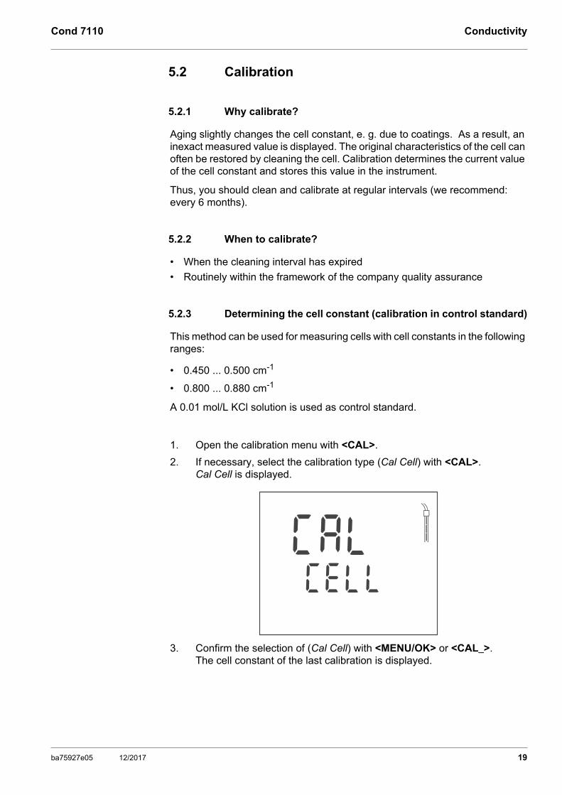
1. Open the calibration menu with <CAL>.
2. If necessary, select the calibration type (Cal Cell) with <CAL>.Cal Cell is displayed.
3. Confirm the selection of (Cal Cell) with <MENU/OK> or <CAL_>.The cell constant of the last calibration is displayed.
LC LE
LAC
ba75927e05 12/2017 19
Conductivity Cond 7110
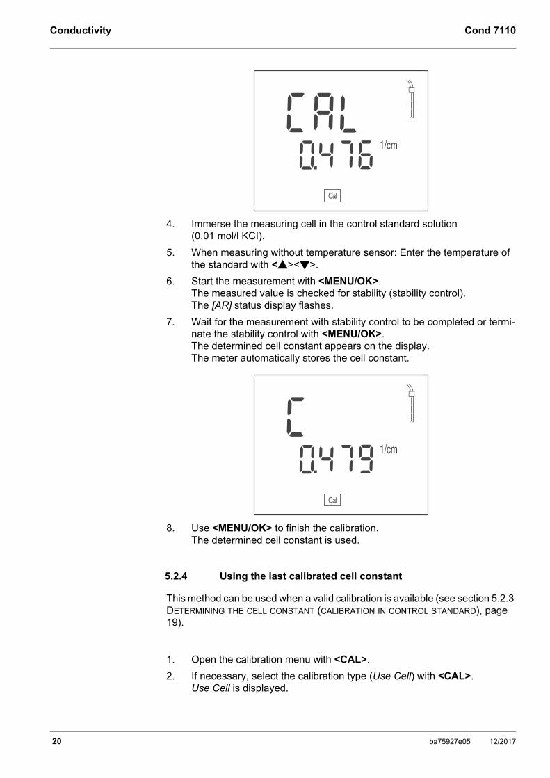
4. Immerse the measuring cell in the control standard solution (0.01 mol/l KCI).
5. When measuring without temperature sensor: Enter the temperature of the standard with <><>.
6. Start the measurement with <MENU/OK>.The measured value is checked for stability (stability control).The [AR] status display flashes.
7. Wait for the measurement with stability control to be completed or termi-nate the stability control with <MENU/OK>. The determined cell constant appears on the display. The meter automatically stores the cell constant.
8. Use <MENU/OK> to finish the calibration.The determined cell constant is used.
5.2.4 Using the last calibrated cell constant
This method can be used when a valid calibration is available (see section 5.2.3 DETERMINING THE CELL CONSTANT (CALIBRATION IN CONTROL STANDARD), page 19).
1. Open the calibration menu with <CAL>.
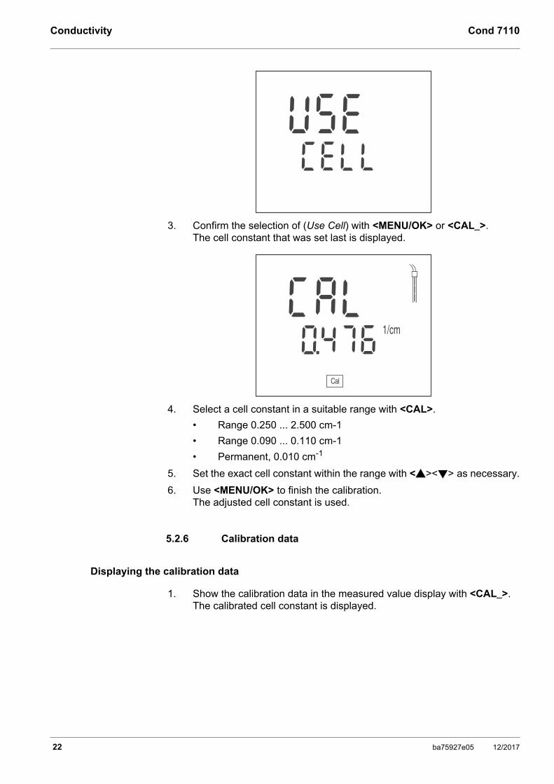
2. If necessary, select the calibration type (Use Cell) with <CAL>.Use Cell is displayed.
1/cm
60 74
LAC
Cal
1/cm
90 74
C
Cal
20 ba75927e05 12/2017

Cond 7110 Conductivity
3. Confirm the selection of (Use Cell) with <MENU/OK> or <CAL_>.The cell constant of the last calibration is displayed.
4. If necessary, select the suitable cell constant with <CAL>.
5. Use <MENU/OK> to finish the calibration.The selected calibrated cell constant is used.
5.2.5 Setting the cell constant manually
This method can be used when the cell constant of the measuring cell is known (e.g. taken from the operating manual of the measuring cell, or from the labeling on the measuring cell).
1. Open the calibration menu with <CAL>.
2. If necessary, select the calibration type (Use Cell) with <CAL>.Use Cell is displayed.
LC LE
ESU
1/cm
90 74
LAC
Cal
ba75927e05 12/2017 21
Conductivity Cond 7110
3. Confirm the selection of (Use Cell) with <MENU/OK> or <CAL_>.The cell constant that was set last is displayed.
4. Select a cell constant in a suitable range with <CAL>.
• Range 0.250 ... 2.500 cm-1
• Range 0.090 ... 0.110 cm-1
• Permanent, 0.010 cm-1
5. Set the exact cell constant within the range with <><> as necessary.
6. Use <MENU/OK> to finish the calibration.The adjusted cell constant is used.
5.2.6 Calibration data
Displaying the calibration data
1. Show the calibration data in the measured value display with <CAL_>.The calibrated cell constant is displayed.
LC LE
ESU
1/cm
60 74
LAC
Cal
22 ba75927e05 12/2017

Cond 7110 Conductivity
Calibration evaluation (conductivity)
After calibration, the meter automatically evaluates the current status of the calibration.
The calibration evaluation is displayed as a sensor symbol.
1/cm
90 74
C
Cal
Display Cell constant [cm-1]
Within the range
0.450 ... 0.500 cm-1
or
0.800 ... 0.880 cm-1
E3 Outside the range
0.450 ... 0.500 cm-1
or
0.800 ... 0.880 cm-1
Eliminate the error(see section 9 WHAT TO DO IF..., page 32)
The calibration evaluation on the display (sensor symbol) flashes when the set cleaning interval has expired and thus reminds you to regularly clean and calibrate the measuring cell (see section 6.1.2 CLEANING INTERVAL, page 25).
ba75927e05 12/2017 23
Settings Cond 7110
6 Settings
The meter has separate setting routines for the measurement settings and system settings.
6.1 Measurement settings (conductivity)
6.1.1 Changing the settings for conductivity measurements
1. Open the setting menu in the measured value display with <MODE_>. The first setting is displayed.
2. If necessary, indicate the required setting with <ENTER>.
3. To change the current setting, press <><>.
4. Confirm the setting with <ENTER>. The setting is stored. The next setting is displayed.
5. Change or confirm the other settings.
orQuit the setting menu with <MODE>.
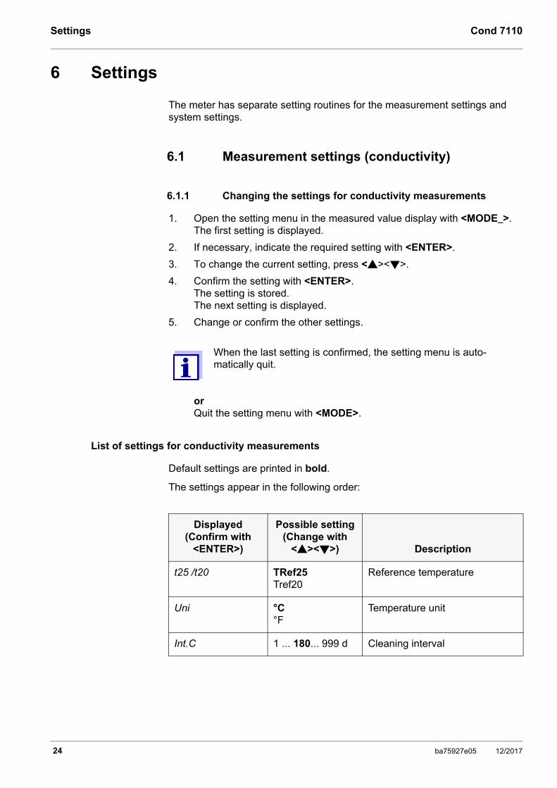
List of settings for conductivity measurements
Default settings are printed in bold.
The settings appear in the following order:
When the last setting is confirmed, the setting menu is auto-matically quit.
Displayed(Confirm with
<ENTER>)
Possible setting(Change with
<><>) Description
t25 /t20 TRef25Tref20
Reference temperature
Uni °C°F
Temperature unit
Int.C 1 ... 180... 999 d Cleaning interval
24 ba75927e05 12/2017

Cond 7110 Settings
6.1.2 Cleaning interval
The cleaning interval is set with the measurement settings (see section 6.1 MEASUREMENT SETTINGS (CONDUCTIVITY), page 24).
The calibration evaluation (sensor symbol) flashes when a valid calibration is available for a measuring cell and the set cleaning interval has expired.
The flashing calibration evaluation reminds you to clean and calibrate the measuring cell regularly (see section 5.2.3 DETERMINING THE CELL CONSTANT (CALIBRATION IN CONTROL STANDARD), page 19).
It is still possible to measure.
6.1.3 Selecting the temperature compensation
1. Open the calibration menu with <CAL>.
2. If necessary, select the Use tC setting with <CAL>.
3. Press <MENU/OK> or <CAL_> to confirm the selection of Use tC.The set temperature compensation is displayed.
4. If necessary, change the setting of the temperature compensation with <CAL>.
• nLF: Nonlinear temperature compensation
• Lin: Linear temperature compensation
If necessary, set the linear temperature coefficient with <><>.
• ----: No temperature compensation (temperature compensation switched off)
5. If necessary, quit the setting of the temperature compensation with <MENU/OK>.The set temperature compensation is used.
Temperature compensation
The calculation of the temperature compensation is based on the preset refer-ence temperature, 20 °C [Tref20] or 25 °C [Tref25].
FLn
035 S/cmm
nLF
Tref25
ARng
ba75927e05 12/2017 25
Settings Cond 7110
You can select one of the following temperature compensation methods:
• Nonlinear temperature compensation (nLF) according to EN 27 888
• Linear temperature compensation (lin) with adjustable coefficients of 0.000 ... 3.000 %/K
• No temperature compensation (---)
Application tips
Select the following temperature compensations given in the table according to the respective test sample:
6.1.4 Setting the TDS factor
The factor to calculate the total dissolved solids is set to 1.00 in the delivery condition.
You can adjust this factor to meet your requirements in the range 0.40 ... 1.00.
1. Select the measured parameter TDS with <MODE>.
2. Set the TDS factor with <><>.
The reference temperature is set in the menu for the parameter conductivity (see section 6.1 MEASUREMENT SETTINGS (CONDUCTIV-ITY), page 24).
The temperature compensation is set in the calibration menu (see section 6.1.3 SELECTING THE TEMPERATURE COMPENSATION, page 25).
Test sampleTemperature compensa-
tion Display
Natural water (ground water, surface water, drinking water)
nLF according to EN 27 888 nLF
Ultrapure water nLF according to EN 27 888 nLF
Salinity (seawater) Automatic nLF according to IOT (International Oceano-graphic Tables)
Sal, nLF
26 ba75927e05 12/2017
Cond 7110 Settings
6.2 Sensor-independent settings
6.2.1 Changing the sensor-independent settings
1. Open the menu for the sensor-independent settings with <MENU/OK_>.The first setting is displayed.
2. To change the current setting, press <><>.
3. Confirm the setting with <ENTER>. The settings are finished.The meter switches to the measuring mode.
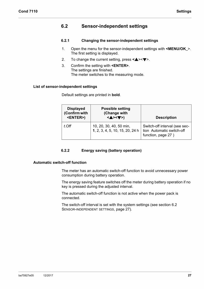
List of sensor-independent settings
Default settings are printed in bold.
6.2.2 Energy saving (battery operation)
Automatic switch-off function
The meter has an automatic switch-off function to avoid unnecessary power consumption during battery operation.
The energy saving feature switches off the meter during battery operation if no key is pressed during the adjusted interval.
The automatic switch-off function is not active when the power pack is connected.
The switch-off interval is set with the system settings (see section 6.2 SENSOR-INDEPENDENT SETTINGS, page 27).
Displayed(Confirm with
<ENTER>)
Possible setting(Change with
<><>) Description
t.Off 10, 20, 30, 40, 50 min, 1, 2, 3, 4, 5, 10, 15, 20, 24 h
Switch-off interval (see sec-tion Automatic switch-off function, page 27 )
ba75927e05 12/2017 27
Reset Cond 7110
7 Reset
You can erase the calibration values and reset (initialize) the measurement and system settings.
7.1 Erasing the calibration values
This function serves to erase the last determined cell constant.
1. Press <On/Off_> to open the menu to erase the calibration data.Ini.C is displayed.
2. Use <><> to display no or YES.
• YES: Erase the calibration values.
• no: Retain the calibration values.
3. Confirm with <MENU/OK>.The menu is finished. The meter switches to the measuring mode.
7.2 Resetting the measurement and system settings
1. Switch on the meter with <On/Off>. The display test appears briefly on the display.
2. During the display test, press <MODE> to open the menu for the reset of the meter settings.Init is displayed.
3. Use <><> to display no or YES.
• YES: Resetting the meter settings.
• no: Retain the meter settings.
4. Confirm with <MENU/OK>.The settings are reset. The menu is finished.The meter switches to the measuring mode.
The calibration values are erased. All other meter settings are retained.The meter subsequently uses the last manually set cell con-
stant in the range 0.250 ... 2.500 cm-1. The measuring system is not calibrated after a reset. Before measuring, make sure the meter uses the cell constant suit-able for the measuring cell.
28 ba75927e05 12/2017

Cond 7110 Reset
Measurement and system settings that can be reset
The following settings are reset to the delivery condition (default): • Measurement settings
• System settings
• Calibration data
The measuring system is possibly not calibrated after a reset. Before measuring, make sure the meter uses the cell con-stant suitable for the measuring cell.
Measurement settings Default
Reference temperature (Tref) t25
Unit of the measured temperature value (Uni )
°C
Calibration interval (Int.C ) 180 d
Temperature compensation nLF
Temperature coefficient of the linear temperature compensation
2.000 %/K
TDS factor 1.00
Manually set cell constant 0.475 cm-1
System settings Default
Switch-off interval (.Off ) 1 h
ba75927e05 12/2017 29
Maintenance, cleaning, disposal Cond 7110
8 Maintenance, cleaning, disposal
8.1 Maintenance
8.1.1 General maintenance activities
The only maintenance activity required is replacing the batteries.
8.1.2 Replacing the batteries
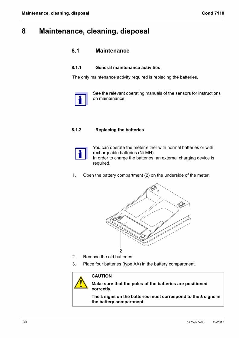
1. Open the battery compartment (2) on the underside of the meter.
2. Remove the old batteries.
3. Place four batteries (type AA) in the battery compartment.
See the relevant operating manuals of the sensors for instructions on maintenance.
You can operate the meter either with normal batteries or with rechargeable batteries (Ni-MH). In order to charge the batteries, an external charging device is required.
CAUTION
Make sure that the poles of the batteries are positioned correctly.
The ± signs on the batteries must correspond to the ± signs in the battery compartment.
2
30 ba75927e05 12/2017

Cond 7110 Maintenance, cleaning, disposal
4. Close the battery compartment tightly.
8.2 Cleaning
Occasionally wipe the outside of the measuring instrument with a damp, lint-free cloth. Disinfect the housing with isopropanol as required.
8.3 Packing
This meter is sent out in a protective transport packing.
We recommend: Keep the packing material. The original packing protects the meter against damage during transport.
8.4 Disposal
At the end of its operational lifetime, the meter must be returned to thedisposal or return system statutory in your country. If you have any questions,please contact your supplier.
When the batteries are nearly empty, the [LoBat] status indicator is displayed.
Dispose of used batteries according to the local regulations of your country. End users within the European Union are obligated to return used batteries (even ecologically compatible ones) to a collection point set up for recycling purposes. Batteries are marked with the crossed-out waste container sym-bol. Therefore, they may not be disposed with the domestic waste.
CAUTION
The housing is made of synthetic material (ABS). Thus, avoid contact with acetone or similar detergents that contain solvents. Remove any splashes immediately.
ba75927e05 12/2017 31

What to do if... Cond 7110
9 What to do if...
9.1 Conductivity
9.1.1 Error message E3
9.1.2 Error message OFL, UFL
The measured value is outside the measuring range.
9.2 General information
9.2.1 [LoBat] Display
More information and instructions on cleaning and exchange of sensors are given in the documentation of your sensor.
Cause Remedy
• Measuring cell contaminated • Clean the measuring cell and replace it if necessary
• Calibration solution not suitable • Check the calibration solutions
Cause Remedy
• Measured value outside the measuring range
• Use suitable conductivity measuring cell
Cause Remedy
Batteries almost empty Replace the batteries (see section 3.3.1 INSERTING THE BATTERIES, page 10)
32 ba75927e05 12/2017
Cond 7110 What to do if...
9.2.2 Instrument does not react to keystroke
9.2.3 Displaying the software version (meter)
Cause Remedy
Operating condition undefined or EMC load unallowed
• Processor reset:
Press the <MENU/OK> and <On/Off> key simultaneously
Cause Remedy
E. g., a question by the service department
• Switch on the meter.
During the display test, display the software version with <MENU/OK>.
ba75927e05 12/2017 33
Technical data Cond 7110
10 Technical data
10.1 Measuring ranges, resolution, accuracy
10.1.1 Measuring ranges, resolution
Parameter Measuring range Resolution
ϰ [µS/cm] 0.000 ... 1.999*
0.00 ... 19.99**
0.0 ... 199.9200 ... 1999
* only possible with cells of the cell constant, 0.010 cm-1
** only possible with cells of the cell constant, 0.010 cm-1 or 0.090 ... 0.110 cm-1
0.0010.010.11
ϰ [mS/cm] 2.00 ... 19.9920.0 ... 199.9200 ... 1000
0.010.11
Specific resis-tance [MOhm*cm]
1.000 ... 1.9992.00 ... 19.9920.0 ... 199.9200 ... 1999
0.0010.010.11
SAL 0.0 ... 70.0according to the IOT table
0.1
TDS [mg/l] 0 ... 1999Factor can be set between 0.40 and 1.00
1
T [°C] - 25.0 ... + 125.0 0.1
T [°F] - 13.0 ... + 257.0 0.1
34 ba75927e05 12/2017
Cond 7110 Technical data
10.1.2 Cell constants
10.1.3 Reference temperature
10.1.4 Accuracy (± 1 digit)
Cell constant Values
Can be calibrated in the ranges
0.800 ... 0.880 cm-1
0.450 ... 0.500 cm-1
Adjustable 0.250 ... 2.500 cm-1
0.090 ... 0.110 cm-1
0.010 cm-1 (permanent)
Reference temperature Values
Adjustable 20 °C (Tref20)25 °C (Tref25)
Parameter AccuracyTemperature of the
test sample
ϰ / Temperature compensation
Nonlinear (nLF)± 0.5 % 0 °C ... + 35 °C
according to EN 27 888+ 35 °C ... + 50 °Cenhanced nLF function
Linear (lin) ± 0.5 % + 10 °C ... + 75 °C
None (Off) ± 0.5 %
SAL / range0 ... 70.0 ± 0.1
± 0.2+ 5 °C ... + 25 °C+ 25 °C ... + 30 °C
TDS [mg/l] / range1 ... 1999 ± 0.5 %
T [°C] / temperature sensor• NTC 30
• PT 1000
± 0.1± 0.1
ba75927e05 12/2017 35

Technical data Cond 7110
10.2 General data
The measuring ranges and accuracy values specified here apply exclusively to the meter. The accuracy of the measuring cells and calibration solutions has to be taken into account additionally.
Dimensions Approx. 230 x 190 x 80 mm
Weight Approx. 1.0 kg
Mechanical structure
Type of protection IP 43
Electrical safety
Protective class III
Test certifi-cates
CE
Ambient conditions
Storing: - 25 °C ... + 65 °C
Operation: +5 °C ... + 55 °CWith the power pack connected: +5 °C ... + 40 °C
Allowable relative humidityYearly mean: < 75 %30 days/year: 95 %Other days: 85 %
Power supply Batteries: 4 x 1.5 V alkali-manganese batteries, type AAOperating time: Approx. 1000 h (operating hours)
Rechargeable batteries: 4 x 1.2 V NiMH rechargeable batteries, type AA(no charging function)
Power pack: Ktec KSAC 0900110W1UV-1Input: 100 ... 240 V ~ / 50 ... 60 Hz / 270 mAOutput: 9 V = / 1.1 AConnection max. Overvoltage category IIPrimary plugs contained in the scope of delivery: Euro, US, UK and Australian.
36 ba75927e05 12/2017

Cond 7110 Technical data
Service inter-face
This interface can be used for service purposes only.
Applicable directives and standards
EMC:• EC directive 2004/108/EC
• EN 61326-1
• EN 61000-3-2
• EN 61000-3-3
• FCC Class A
Instrument safety: • EC directive 2006/95/EC
• EN 61010-1
IP type of protection: • EN 60529
FCC Class A Equipment Statement
Note: This equipment has been tested and found to comply with the limits for a Class A digital device, pursuant to Part 15 of the FCC Rules. These limits are designed to provide reasonable protection against harmful interference when the equipment is operated in a commercial environment. This equipment generates, uses, and can radiate radio frequency energy and, if not installed and used in accordance with the instruction manual, may cause harmful interference to radio communications. Operation of this equipment in a residential area is likely to cause harmful interference in which case the user will be required to correct the interference at his own expense.Changes or modifications not expressly approved by the manufacturer could void the user‘s authority to operate the equipment.
ba75927e05 12/2017 37
Glossary Cond 7110
11 Glossary
11.1 Conductivity
Specialist term Description
Cell constant, C
Characteristic quantity of a conductivity measuring cell, depending on the geometry.
Conductivity Short form of the expression, specific electrical conductiv-ity. It corresponds to the reciprocal value of the resistivity. It is a measured value of the ability of a substance to con-duct an electric current. In water analysis, the electrical conductivity is a dimension for the ionized substances in a solution.
Reference temperature
Fixed temperature value to compare temperature-depen-dent measured values. For conductivity measurements, the measured value is converted to a conductivity value at a reference temperature of 20 °C or 25 °C.
Resistance Short name for the electrolytic resistivity. It corresponds to the reciprocal value of the electrical conductivity.
Salinity The absolute salinity SA of seawater corresponds to the relationship of the mass of dissolved salts to the mass of the solution (in g/kg). In practice, this dimension cannot be measured directly. Therefore, the practical salinity accord-ing to IOT is used for oceanographic monitoring. It is determined by measuring the electrical conductivity.
Salt content General designation for the quantity of salt dissolved in water.
Temperature coefficient
Value of the slope of a linear temperature function
Temperature compensation
Name of a function that considers the temperature influ-ence on the measurement and converts it accordingly. Depending on the measured parameter to be determined, the temperature compensation functions in different ways. For conductimetric measurements, the measured value is converted to a defined reference temperature. For potenti-ometric measurements, the slope value is adjusted to the temperature of the test sample but the measured value is not converted.
TRef=
Meas*1
1 + (T - )* TRef
38 ba75927e05 12/2017
Cond 7110 Glossary
11.2 General information
Specialist term Description
Adjusting To manipulate a measuring system so that the rele-vant value (e. g. the displayed value) differs as little as possible from the correct value or a value that is regarded as correct, or that the difference remains within the tolerance.
AutoRange Name of the automatic selection of the measuring range.
Calibration Comparing the value from a measuring system (e. g. the displayed value) to the correct value or a value that is regarded as correct. Often, this expression is also used when the measuring system is adjusted at the same time (see adjusting).
Measured param-eter
The measured parameter is the physical dimension determined by measuring, e. g. pH, conductivity or D.O. concentration.
Measured value The measured value is the special value of a mea-sured parameter to be determined. It is given as a combination of the numerical value and unit (e. g. 3 m; 0.5 s; 5.2 A; 373.15 K).
Molality Molality is the quantity (in Mol) of a dissolved sub-stance in 1000 g solvent.
Potentiometry Name of a measuring technique. The signal (depend-ing on the measured parameter) of the electrode is the electrical potential. The electrical current remains constant.
Reset Restoring the original condition of all settings of a measuring system.
Resolution Smallest difference between two measured values that can be displayed by a meter.
Stability control (AutoRead )
Function to control the measured value stability.
ba75927e05 12/2017 39

Glossary Cond 7110
Standard solution The standard solution is a solution where the mea-sured value is known by definition. It is used to cali-brate a measuring system.
Temperature func-tion
Name of a mathematical function expressing the tem-perature behavior of a test sample, a sensor or part of a sensor.
Test sample Designation of the test sample ready to be measured. Normally, a test sample is made by processing the original sample. The test sample and original sample are identical if the test sample was not processed.
Specialist term Description
40 ba75927e05 12/2017

Cond 7110 Index
12 Index
AAR . . . . . . . . . . . . . . . . . . . . . . . . . . . . . . . 14Automatic switch-off function . . . . . . . . . . . 27AutoRead . . . . . . . . . . . . . . . . . . . . . . . . . . 17
BBattery compartment . . . . . . . . . . . . . . 11, 30
CCalibration . . . . . . . . . . . . . . . . . . . . . . . . . 19Calibration evaluation (conductivity) . . . . . 23Cell constant . . . . . . . . . . . . . . . . . . . . . . . 19
DDefault (measurement settings) . . . . . . . . . 29Default (system settings) . . . . . . . . . . . . . . 29Determining the cell constant . . . . . . . . . . . 19Display . . . . . . . . . . . . . . . . . . . . . . . . . . . . 14
IInitial commissioning . . . . . . . . . . . . . . . . . 10Initialize . . . . . . . . . . . . . . . . . . . . . . . . . . . 28
KKeys . . . . . . . . . . . . . . . . . . . . . . . . . . . . . . 13
MMeasured value display . . . . . . . . . . . . . . . 16Measuring (conductivity) . . . . . . . . . . . . . . 17
RReset . . . . . . . . . . . . . . . . . . . . . . . . . . . . . 28
SSafe operation . . . . . . . . . . . . . . . . . . . . . . . 9Scope of delivery . . . . . . . . . . . . . . . . . . . . 10Setting the cell constant . . . . . . . . . . . . . . . 21Socket field . . . . . . . . . . . . . . . . . . . . . . . . 15Stability control . . . . . . . . . . . . . . . . . . . . . . 17
TTDS factor . . . . . . . . . . . . . . . . . . . . . . . . . 26Temperature compensation . . . . . . . . . . . . 25
UUsing the calibrated cell constant . . . . . . . 20
ba75927e05 12/2017 41

Index Cond 7110
42 ba75927e05 12/2017


What can Xylem do for you?
We're a global team unified in a common purpose: creating innovative solutions to
meet our world's water needs. Developing new technologies that will improve the way
water is used, conserved, and re-used in the future is central to our work. We move,
treat, analyze, and return water to the environment, and we help people use water
efficiently, in their homes, buildings, factories and farms. In more than 150 countries, we
have strong, long-standing relationships with customers who know us for our powerful
combination of leading product brands and applications expertise, backed by a legacy
of innovation.
Xylem Analytics Germany GmbH
Dr.-Karl-Slevogt-Str. 1
82362 Weilheim
Germany
Xylem Analytics Germany
Sales GmbH & Co. KG
WTW
Dr.-Karl-Slevogt-Str. 1
82362 Weilheim
Germany
Tel.:
Fax:
Internet:
+49 881 183-325
+49 881 183-414
www.WTW.com
Service address:
®
For more information on how Xylem can help you, go to xyleminc.com.
![6819 BT Freestyle 7110 [1]](https://static.documents.pub/doc/80x56/61937a87410d5970372554ae/6819-bt-freestyle-7110-1.jpg)


