26
CONDENSATE SYSTEM RAVI PAL SINGH DUSHYANT SINGH (GROUP-C)
| Date post: | 18-Jul-2015 |
| Category: |
Technology |
| Upload: | ravi-pal-singh |
| View: | 185 times |
| Download: | 3 times |
CONDENSATE SYSTEM
RAVI PAL SINGH
DUSHYANT SINGH
(GROUP-C)
LAYOUT
• CONDENSATE FLOW • EXTRACTION STEAM AND DRIP FLOW • CONDENSER • CEP • SJAE • CSC & GSC • LPH • PARAMETERS CHART OF LP HEATERS • START UP PROCEDURES • SHUTDOWN PROCEDURES
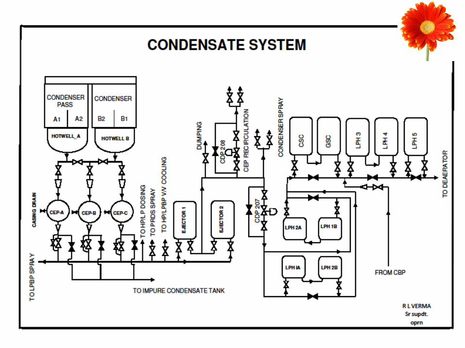
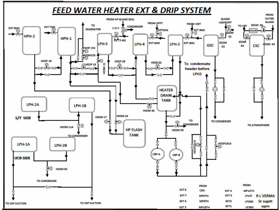
CONDENSATE FLOW
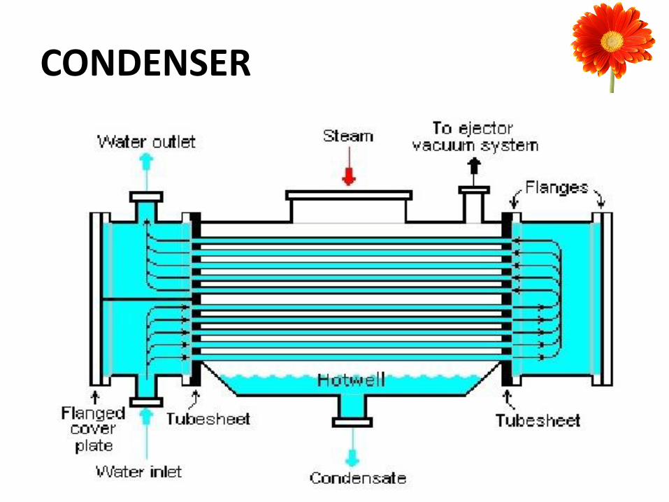
CONDENSER
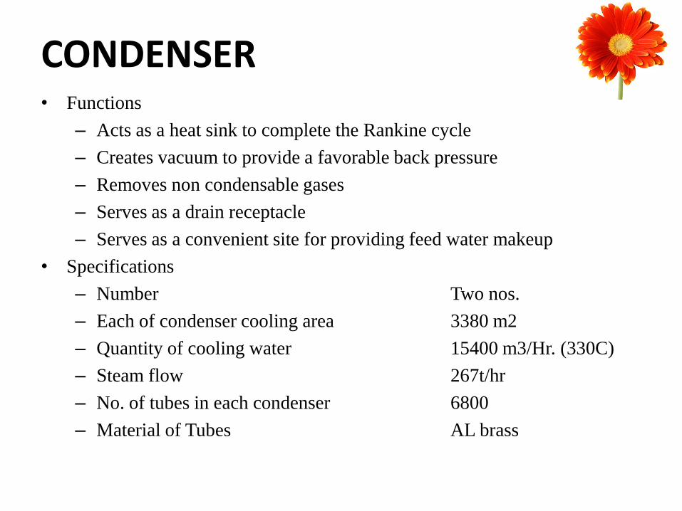
CONDENSER • Functions
– Acts as a heat sink to complete the Rankine cycle
– Creates vacuum to provide a favorable back pressure
– Removes non condensable gases
– Serves as a drain receptacle
– Serves as a convenient site for providing feed water makeup
• Specifications
– Number Two nos.
– Each of condenser cooling area 3380 m2
– Quantity of cooling water 15400 m3/Hr. (330C)
– Steam flow 267t/hr
– No. of tubes in each condenser 6800
– Material of Tubes AL brass
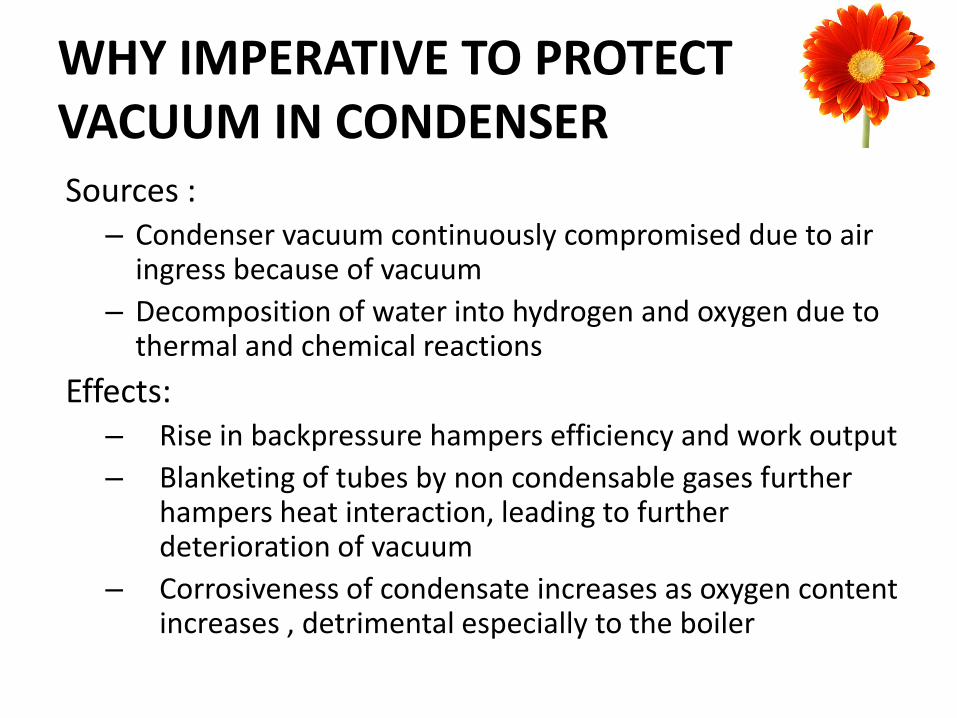
WHY IMPERATIVE TO PROTECT VACUUM IN CONDENSER Sources :
– Condenser vacuum continuously compromised due to air ingress because of vacuum
– Decomposition of water into hydrogen and oxygen due to thermal and chemical reactions
Effects: – Rise in backpressure hampers efficiency and work output
– Blanketing of tubes by non condensable gases further hampers heat interaction, leading to further deterioration of vacuum
– Corrosiveness of condensate increases as oxygen content increases , detrimental especially to the boiler
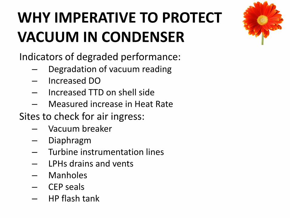
Indicators of degraded performance: – Degradation of vacuum reading – Increased DO – Increased TTD on shell side – Measured increase in Heat Rate
Sites to check for air ingress: – Vacuum breaker – Diaphragm – Turbine instrumentation lines – LPHs drains and vents – Manholes – CEP seals – HP flash tank
WHY IMPERATIVE TO PROTECT VACUUM IN CONDENSER
– Increased wetness in last stages of LPT
– Under cooling of condensate causing less effective regeneration
– APC of additional CW Pumps and CT fans
THE FLIP SIDE OF HIGH VACUUM
CEP
• Functions
– Flow in condensate cycle from Hot well to Deaerator
– CEP discharge gives a provision for the following:
• Exhaust hood spray
• HP/LP bypass valve cooling
• LP bypass spray
• PRDS spray
• HP/LP dozing
CEP and Hotwell level NPSH
• All pumps have a designed NPSH (Net Positive Suction Head) requirement for their operation
Cavitation
• If the suction head is reduced (due to low hot well level) to a value such that the net head at suction falls below atmospheric pressure at that temperature, cavitation , in other words localized boiling of the working liquid is impending
• Localized vapourization occurs and bubbles move through the impeller at near sonic velocities
• When these bubbles suddenly burst on collision with impeller, severe vibrations and noise is observed
• Cavitation causes reduced pump capacity, metal removal, reduced flow, loss in efficiency and noise.
CEP EMERGENCIES
–If CEP motor tripped reduce load to maintain deaerator level, try starting standby CEP.
–If CEP tripped on hot well level low, increase hot well level by immediately starting all CTP and take CEP in service one by one.
–If CEP tripped on discharge pressure low (malfunctioning of CDP-207 /208), manually operate their bypass valves and take CEP in service one by one.
–If CEP rotating in reverse direction due to passing in NRV, possible threat of pump seizure, immediately close discharge valve.
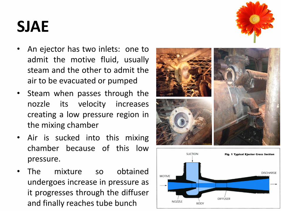
SJAE • An ejector has two inlets: one to
admit the motive fluid, usually steam and the other to admit the air to be evacuated or pumped
• Steam when passes through the nozzle its velocity increases creating a low pressure region in the mixing chamber
• Air is sucked into this mixing chamber because of this low pressure.
• The mixture so obtained undergoes increase in pressure as it progresses through the diffuser and finally reaches tube bunch

SJAE = SAVING IN POWER?
• Better energy conversion in SJAE(low grade thermal energy) in comparison to vacuum pumps (higher grade electrical energy).
• Drip formation in the condensing steam, provides regenerative heat to the condensate.
• Absence of moving mechanical parts in SJAE eliminates wear and tear of components.
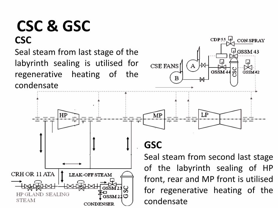
CSC & GSC CSC Seal steam from last stage of the labyrinth sealing is utilised for regenerative heating of the condensate
GSC Seal steam from second last stage of the labyrinth sealing of HP front, rear and MP front is utilised for regenerative heating of the condensate
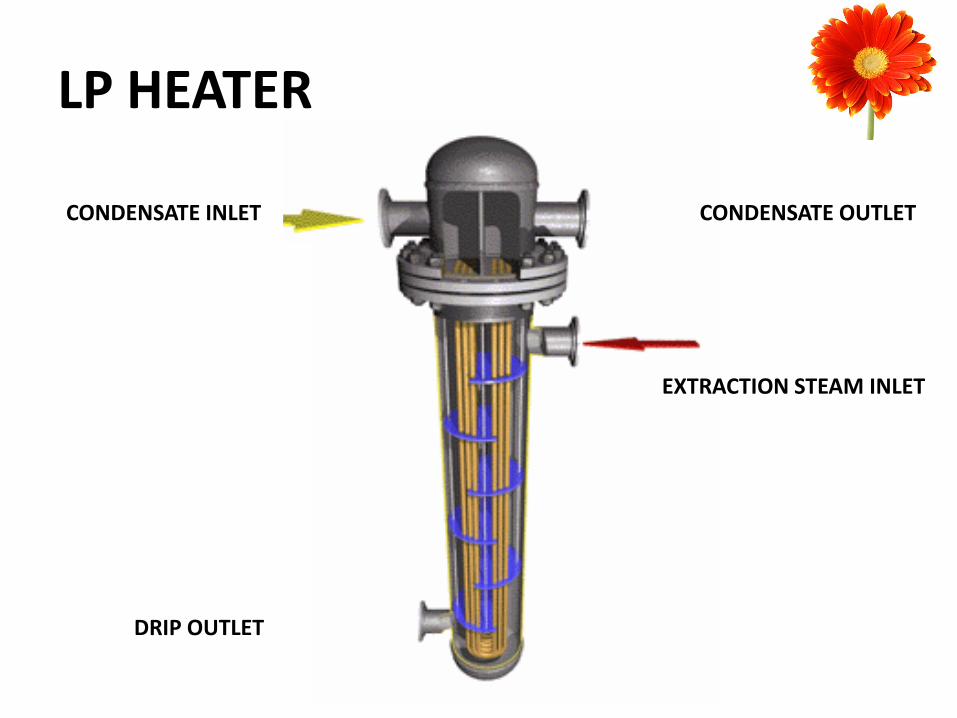
LP HEATER
CONDENSATE INLET CONDENSATE OUTLET
EXTRACTION STEAM INLET
DRIP OUTLET
WHY LP HEATERS?
• Regenerative heating and thus overall efficiency gain.(lead to ‘’Carnotization’’ of Rankine cycle )
• Reduction in loading on LP turbine(design criteria).
• Minimizing thermal effects in boiler.
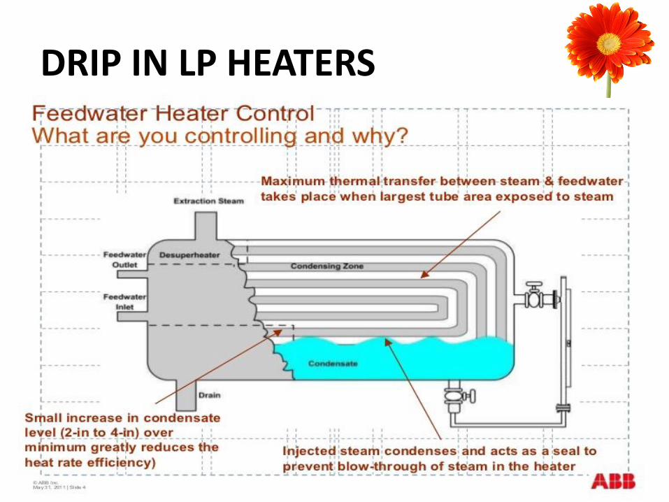
DRIP IN LP HEATERS
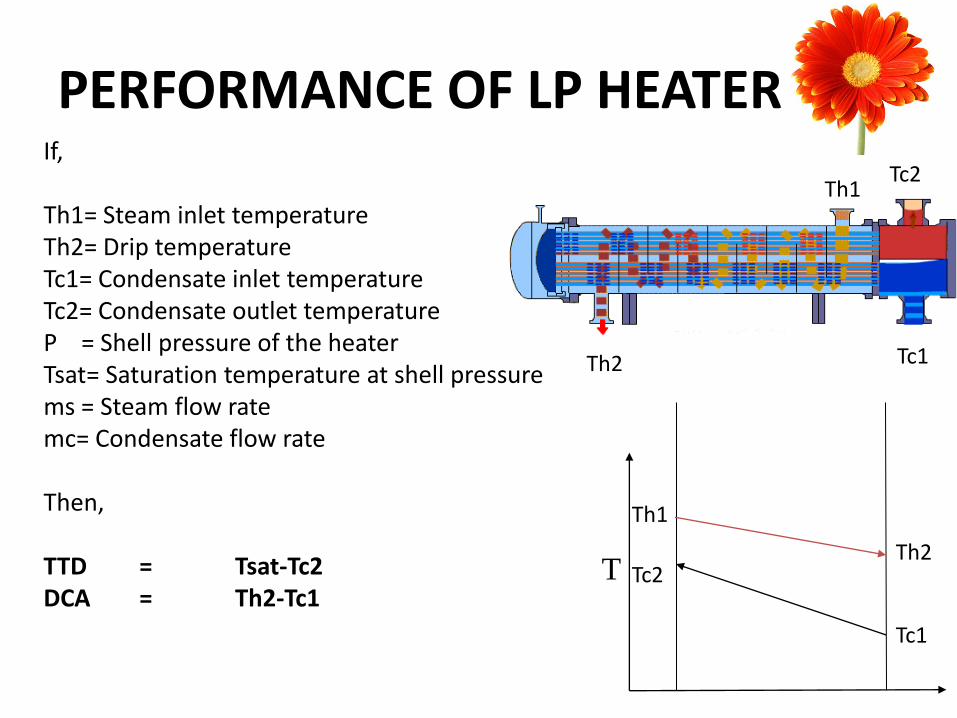
PERFORMANCE OF LP HEATER
Tc1
Tc2 Th1
Th2
T Tc2
Tc1
Th1
Th2
If, Th1= Steam inlet temperature Th2= Drip temperature Tc1= Condensate inlet temperature Tc2= Condensate outlet temperature P = Shell pressure of the heater Tsat= Saturation temperature at shell pressure ms = Steam flow rate mc= Condensate flow rate Then, TTD = Tsat-Tc2 DCA = Th2-Tc1
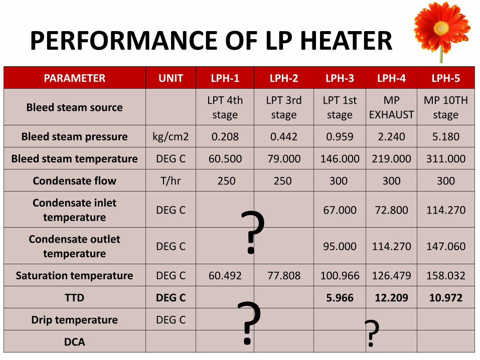
PERFORMANCE OF LP HEATER PARAMETER UNIT LPH-1 LPH-2 LPH-3 LPH-4 LPH-5
Bleed steam source LPT 4th stage
LPT 3rd stage
LPT 1st stage
MP EXHAUST
MP 10TH stage
Bleed steam pressure kg/cm2 0.208 0.442 0.959 2.240 5.180
Bleed steam temperature DEG C 60.500 79.000 146.000 219.000 311.000
Condensate flow T/hr 250 250 300 300 300
Condensate inlet temperature
DEG C 67.000 72.800 114.270
Condensate outlet temperature
DEG C 95.000 114.270 147.060
Saturation temperature DEG C 60.492 77.808 100.966 126.479 158.032
TTD DEG C 5.966 12.209 10.972
Drip temperature DEG C
DCA
?
? ?
LPH EMERGENCIES
• LPH out on drip level high
– Ensure all motorized valves and extraction NRVs are closed.
– Check all drip valves are open.
– If heater level still rising, suspected tube leakage, immediately isolate from condensate side.
HEATER DRAIN TANK AND BOOSTER PUMP
• Condensate flow at low power pump (compared to CEP) to meet the main condensate flow requirement.
• Direct mixing of high energy drip (compared to hot well) to condensate flow.
STARTUP PROCEDURES
• No PTWs are pending. • Electrical supplies should be normal. • CW to condenser charged. • Suction valves of all CEPs and CBPs are open • Equalizing valve to CEPs are opened • Cooling lines of CEP and CBP are charged. • Vents of LP heaters, HDT and GSC should be opened. • Hot well level should be normal. • Close discharge valve of 1st CEP. • Give start command to 1st CEP and open discharge valve slowly. • Close all the vents when continuous flow of water is observed. • Now maintain hot well and deaerator level, if necessary take
successive CEPs in service.
SHUTDOWN PROCEDURES
• Ensure all extractions NRVs and motorized valves are closed.
• Maintain hot well and deaerator level by running of at least one CEP.
• In case of long shut down open vacuum breaker and isolate PRDS.

THANK YOU


![10. Feed Water, Condensate and Steam System [Compatibility Mode].pdf](https://static.documents.pub/doc/80x56/563db9b8550346aa9a9f492b/10-feed-water-condensate-and-steam-system-compatibility-modepdf.jpg)


