only suitable foroperation with heating oil EL(low sulphur)
UltraOil® (16-35) UltraOil® (50-80)
4 210 253 / 00 - 07/11
4 210 253 / 002 Table of contents
1. For optimum use of the heating system, read the operating instructions! .................... 41.1 Important addresses and telephone numbers ..................................................................................... 41.2 Key to symbols used .............................................................................................................................. 41.3 System data ............................................................................................................................................. 51.4 Calculation basis ..................................................................................................................................... 51.5 Burner setting .......................................................................................................................................... 6
2. Safety information ................................................................................................................ 72.1 Intended use ............................................................................................................................................ 7
3. Customer service ................................................................................................................. 8
4. Functional principle of the heating system ....................................................................... 9
5. System start-up .................................................................................................................. 115.1 Checks prior to start-up ....................................................................................................................... 115.2 Switching on the system ...................................................................................................................... 11
6. Heating system control ..................................................................................................... 126.1 What is the function of the heating controller TopTronic® T .............................................................. 126.2 How you can save energy .................................................................................................................... 126.3 Basic display ......................................................................................................................................... 126.4 Operating and display elements .......................................................................................................... 136.4.1 Function of the operating elements ......................................................................................................... 136.4.2 Basic procedure for changing settings .................................................................................................... 136.4.3 What to do if... ......................................................................................................................................... 146.4.4 Control elements on the boiler control panel ........................................................................................... 156.5 Main settings ......................................................................................................................................... 176.5.1 Changing the room temperature ............................................................................................................. 176.5.2 Setting the reduced (night time) temperature .......................................................................................... 186.6 Operating modes ................................................................................................................................... 196.6.1 Operating mode functions ....................................................................................................................... 196.6.2 Operating modes for holiday and absence? ............................................................................................ 206.6.3 Changing the operating mode - for “HOLIDAY TIL”, “ABSENT TIL” and “PARTY TIL” .............................. 216.6.4 Changing operating mode - for “AUTOMATIC”, “SUMMER” , “HEATING”, “RED. HEATING” and
“STANDBY” ............................................................................................................................................. 226.7 Switching times (heating times) .......................................................................................................... 236.7.1 Standard heating times ........................................................................................................................... 236.7.2 Table for recording individual switching times ......................................................................................... 236.7.3 Changing the switching times (heating times) ......................................................................................... 246.7.4 Copying switching times .......................................................................................................................... 276.8 Heating curve ........................................................................................................................................ 296.8.1 Heating curve (heating characteristic) information .................................................................................. 296.8.2 Changing the heating curve (heating characteristic) ............................................................................... 306.9 Domestic hot water ............................................................................................................................... 316.9.1 Adjusting the domestic hot water temperature ........................................................................................ 316.9.2 Manual hot water loading ........................................................................................................................ 326.9.3 Domestic hot water economy temperature (reduced temperature) ......................................................... 336.10 Further settings ..................................................................................................................................... 356.10.1 Setting the clock ...................................................................................................................................... 356.10.2 Setting the date ....................................................................................................................................... 366.10.3 Changing between summer and winter time ........................................................................................... 366.10.4 Setting the language ............................................................................................................................... 376.10.5 Reloading the standard switching times program - Deleting the own time program ............................... 386.10.6 Manual operating mode ......................................................................................................................... 406.10.7 Alarms ..................................................................................................................................................... 416.10.8 Changing the maximum boiler temperature ............................................................................................ 42
4 210 253 / 00 3Table of contents
6.11 System information ............................................................................................................................... 446.11.1 Information key for system temperatures and heating circuit information ............................................... 446.11.2 Special symbols ...................................................................................................................................... 456.11.3 Maintenance message ............................................................................................................................ 456.11.4 Optional accessories ............................................................................................................................... 45
7. Oil tank and burner ............................................................................................................ 467.1 Fuel ......................................................................................................................................................... 467.2 Filling the oil tank .................................................................................................................................. 467.3 Burner setting ........................................................................................................................................ 467.4 Boiler room and supply of fresh air..................................................................................................... 467.5 Putting into service ............................................................................................................................... 467.6 Taking out of service ............................................................................................................................ 467.7 Maintenance of the burner ................................................................................................................... 46
8. Maintenance and checks ................................................................................................... 47
9. Check list in case of faults ................................................................................................ 49
10. This is how you can save energy ..................................................................................... 50
11. Hoval Service / sales program .......................................................................................... 51
4 210 253 / 004 Operating instructions
1. For optimum use of the heating system, read the operating instructions!
These instructions will provide you with all the information you need for an optimal use of your heating system.An optimally adjusted heating system can not only save you a lot of grief, but also a lot of money.
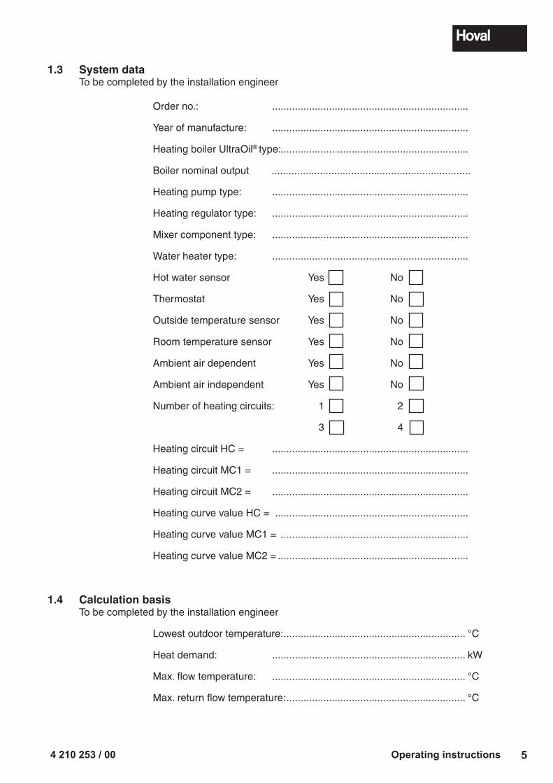
Max. flow temperature: .................................................................... °C
Max. return flow temperature: ............................................................... °C
4 210 253 / 006 Operating instructions
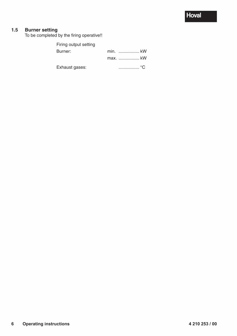
1.5 Burner settingTo be completed by the firing operative!!
Firing output setting
Burner: min. ................. kW
max. ................. kW
Exhaust gases: ................. °C
4 210 253 / 00 7Safety information
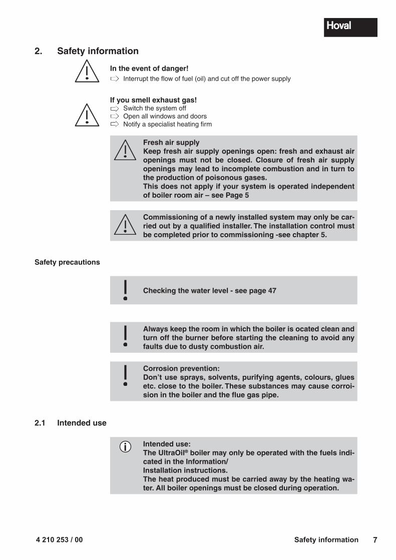
2. Safety information
In the event of danger! Interrupt the flow of fuel (oil) and cut off the power supply
If you smell exhaust gas! Switch the system off Open all windows and doors Notify a specialist heating firm
Fresh air supplyKeep fresh air supply openings open: fresh and exhaust air openings must not be closed. Closure of fresh air supply openings may lead to incomplete combustion and in turn to the production of poisonous gases.This does not apply if your system is operated independent of boiler room air – see Page 5
Commissioning of a newly installed system may only be car-ried out by a qualified installer. The installation control must be completed prior to commissioning -see chapter 5.
Safety precautions
Checking the water level - see page 47
Always keep the room in which the boiler is ocated clean and turn off the burner before starting the cleaning to avoid any faults due to dusty combustion air.
Corrosion prevention:Don’t use sprays, solvents, purifying agents, colours, glues etc. close to the boiler. These substances may cause corroi-sion in the boiler and the flue gas pipe.
2.1 Intended use
i Intended use:The UltraOil® boiler may only be operated with the fuels indi-cated in the Information/Installation instructions.The heat produced must be carried away by the heating wa-ter. All boiler openings must be closed during operation.
4 210 253 / 008 Customer service
You should read these instructions thoroughly before the system is commissioned!
Dear Customer,With the Hoval UltraOil® you have acquired a product manufactured according to the state-of-the-art and highest quality standards.Please ensure that the delivery is consistent with your order and check it is complete. Also check for possible damage in transit and inform the nearest Customer Service centre if there is any. For insurance reasons it will not be possible to accept any subsequent claims.For the correct installation and operation of your Hoval UltraOil®, all applicable laws, regulations and standards must be complied with; in particular the regulations of the respective energy supply company. In case of queries, please contact your specialist installer or the nearest Hoval Customer Service centre.Assembly or installation of the heating boiler may only be carried out by trained personnel of an approved installation company. Before starting the boiler for the first time, an installation inspection and approval of the overall installation by the installer are required.To guarantee safe and trouble-free operation, operate your Hoval boiler only accord-ing to these operating instructions.The boiler may only be used for its intended purpose and fuels for which it is suitable on the basis of its design and for which it has been approved by Hoval.Do not carry out any changes to the system, otherwise all claims under the guarantee will be invalidated. Conversion kits are to be installed and the installation approved by authorised installers or by the Hoval Customer Service.The reliable and safe functioning of a oil boiler, as well as the achievement of an optimal effectiveness and clean combustion are only possible and guaranteed if the system is maintained and cleaned at least once every year.In the event of a fault or in case of damage, please contact the Hoval Customer Service to inquire about the necessary repairs. In the meantime, shut down the unit to avoid any damage.With the acquisition of a Hoval unit you also obtain a comprehensive guarantee protection, as indicated in the guarantee conditions of the guarantee pass for your unit.This guarantee is, however, dependent on the observance of the operating and installation instructions and on compliance with the applicable legal regulations. Non-compliance with the above will invalidate all liability and warranty claims against Hoval.Provided it is used correctly, your Hoval boiler will ensure you enjoy a well heated home for many years.
The Hoval Customer ServiceIf you have any doubts in regard to the operation of your Hoval boiler, or minor faults affect its correct functioning, please contact the nearest Hoval Customer Service centre. A telephone call is often enough when it comes to solving small problems. Our trained Customer Service staff will do everything in their hands to help you.If a fault can not be solved in this way, a service technician will visit you in order to solve the problem. We hope you understand that, except in urgent cases, this is not always immediately possible.Take advantage of the offer of the Hoval Customer Services for extending the service life of your Hoval boiler, and ask for a service agreement. Your Customer Services advisor will be pleased to give you information.You will find the addresses on the last page.
3. Customer service
i
4 210 253 / 00 9Functional principle of the heating system
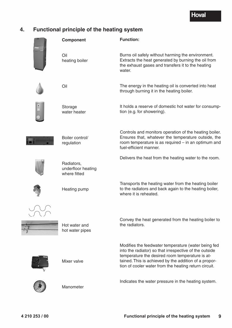
4. Functional principle of the heating system
Function:
Burns oil safely without harming the environment.Extracts the heat generated by burning the oil from the exhaust gases and transfers it to the heating water.
The energy in the heating oil is converted into heat through burning it in the heating boiler.
It holds a reserve of domestic hot water for consump-tion (e.g. for showering).
Controls and monitors operation of the heating boiler.Ensures that, whatever the temperature outside, the room temperature is as required – in an optimum and fuel-efficient manner.
Delivers the heat from the heating water to the room.
Transports the heating water from the heating boiler to the radiators and back again to the heating boiler, where it is reheated.
Convey the heat generated from the heating boiler to the radiators.
Modifies the feedwater temperature (water being fed into the radiator) so that irrespective of the outside temperature the desired room temperature is at-tained. This is achieved by the addition of a propor-tion of cooler water from the heating return circuit.
Indicates the water pressure in the heating system.
Component
Oil heating boiler
Oil
Storagewater heater
Boiler control/regulation
Radiators,underfloor heating where fitted
Heating pump
Hot water and hot water pipes
Mixer valve
Manometer
4 210 253 / 0010 Functional principle of the heating system
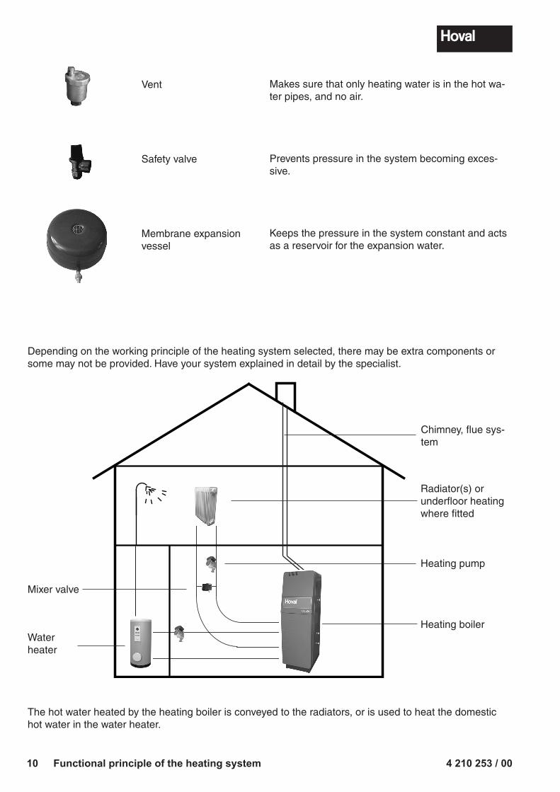
Makes sure that only heating water is in the hot wa-ter pipes, and no air.
Prevents pressure in the system becoming exces-sive.
Keeps the pressure in the system constant and acts as a reservoir for the expansion water.
Vent
Safety valve
Membrane expansion vessel
Depending on the working principle of the heating system selected, there may be extra components or some may not be provided. Have your system explained in detail by the specialist.
Radiator(s) or underfloor heating where fitted
Heating pump
Heating boiler
Mixer valve
Waterheater
Chimney, flue sys-tem
The hot water heated by the heating boiler is conveyed to the radiators, or is used to heat the domestic hot water in the water heater.
4 210 253 / 00 11System start-up
5. System start-up
Commissioning of a newly installed system may only be carried out by a quali-fied installer. A full installation check must be completed prior to start-up.
- Set the main SYSTEM switch to “0” - Open the shut-off valves in the flow and return lines. - With the UltraOil® fill the odour trap (siphon) in the condensate drain pipe with water before starting up the system.
5.1 Checks prior to start-up
Check the water level in the heating system.
The heating system must be filled with water and all the air removed.Observe the regulations regarding antifreeze and water treatment.
Open the shut-off valves in the flow and return lines. Check the fresh air supply to the heating system. Check the settings for the operating modes.
5.2 Switching on the system
Switch on the main switch. Set the boiler control unit to the desired operating mode and tempera-
ture.
i
i
4 210 253 / 0012 Heating system control
6. Heating system control
6.1 What is the function of the heating controller TopTronic® T
The boiler controller is, in conjunction with the temperature sensor connected to it, so to speak, the brain of the heating system.Its main functions are:
- maintaining the desired room temperature independently of the outdoor tem-perature
- heating the living space when required - producing warm water (e.g. for showering) only when required - displaying information
Further functions: - Input of desired temperatures and operating modes - Turn the burner ON/OFF - Temperature monitor
The correct settings for the heating system have already been applied by Hoval, or the installer, during commissioning. Any changes to those settings should only be carried out if you go away on a trip or if your home is to cold or too warm. An overview of the most frequent questions/answers can be found on pages 14 and 19 of these instructions.
6.2 How you can save energy
For your benefit and for the environmentUsing energy more efficiently by avoiding unnecessary losses: With little effort you can optimise the operation of your system and make it worth while.
- You can save money. So much money in fact, that every sixth year, the amount saved will cover you bill for heating oil.
- Every year you can save as much energy as is equivalent to the output of a whole bath full of heating oil.
In autumn, it is worth while turning the heating off again on warm daysThis prevents the heating system from producing unnecessary heat in the morn-ing, due to low outdoor temperatures, and overheating the house. Turning the heating on or off depending on the weather conditions is one of the most effective energy saving measures. If you want to save yourself going down the basement, you may want to consider acquiring a “remote control” from Hoval, which will allow you to operate and control the heating comfortably from your living room.
6.3 Basic display
The basic display shows the day of the week, date and time of the day, as well as the current boiler temperature and room temperature (room station).
i
i
i
ENERGY
4 210 253 / 00 13Heating system control
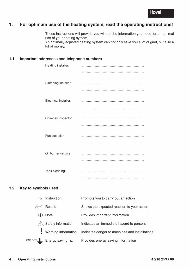
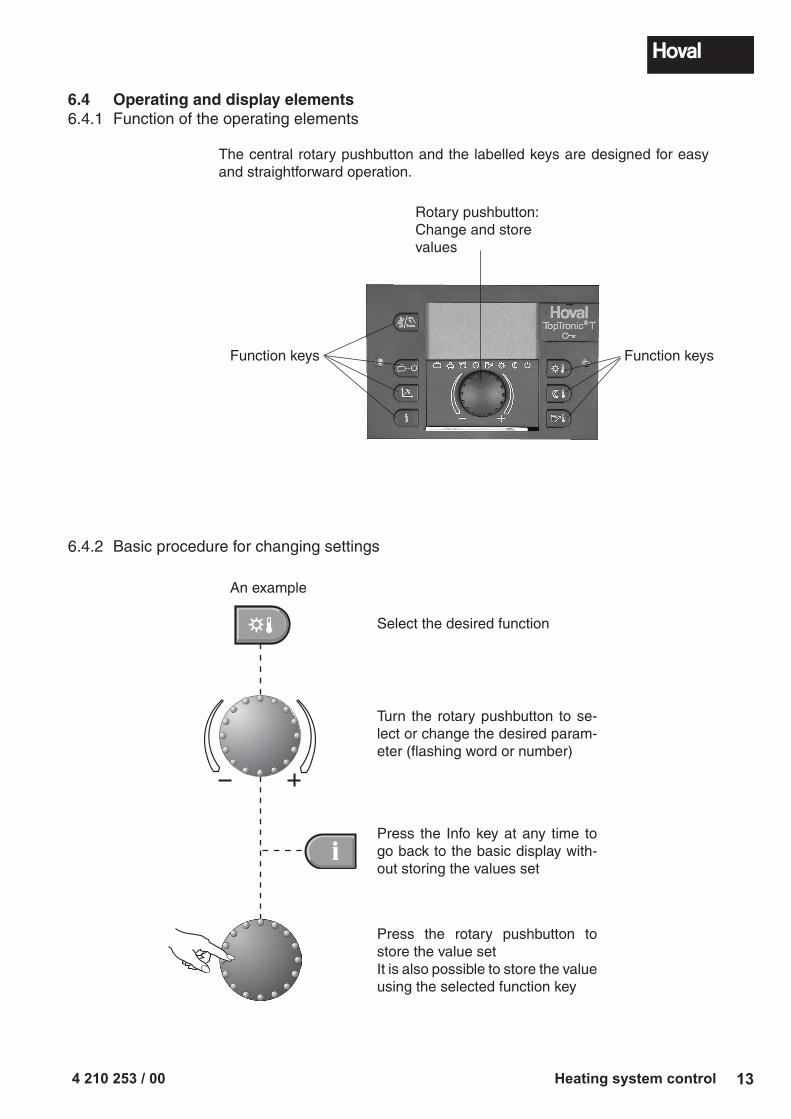
6.4 Operating and display elements6.4.1 Function of the operating elements
The central rotary pushbutton and the labelled keys are designed for easy and straightforward operation.
6.4.2 Basic procedure for changing settings
An example
Select the desired function
Turn the rotary pushbutton to se-lect or change the desired param-eter (flashing word or number)
Press the Info key at any time to go back to the basic display with-out storing the values set
Press the rotary pushbutton to store the value setIt is also possible to store the value using the selected function key
Rotary pushbutton:Change and store values
Function keysFunction keys
4 210 253 / 0014 Heating system control
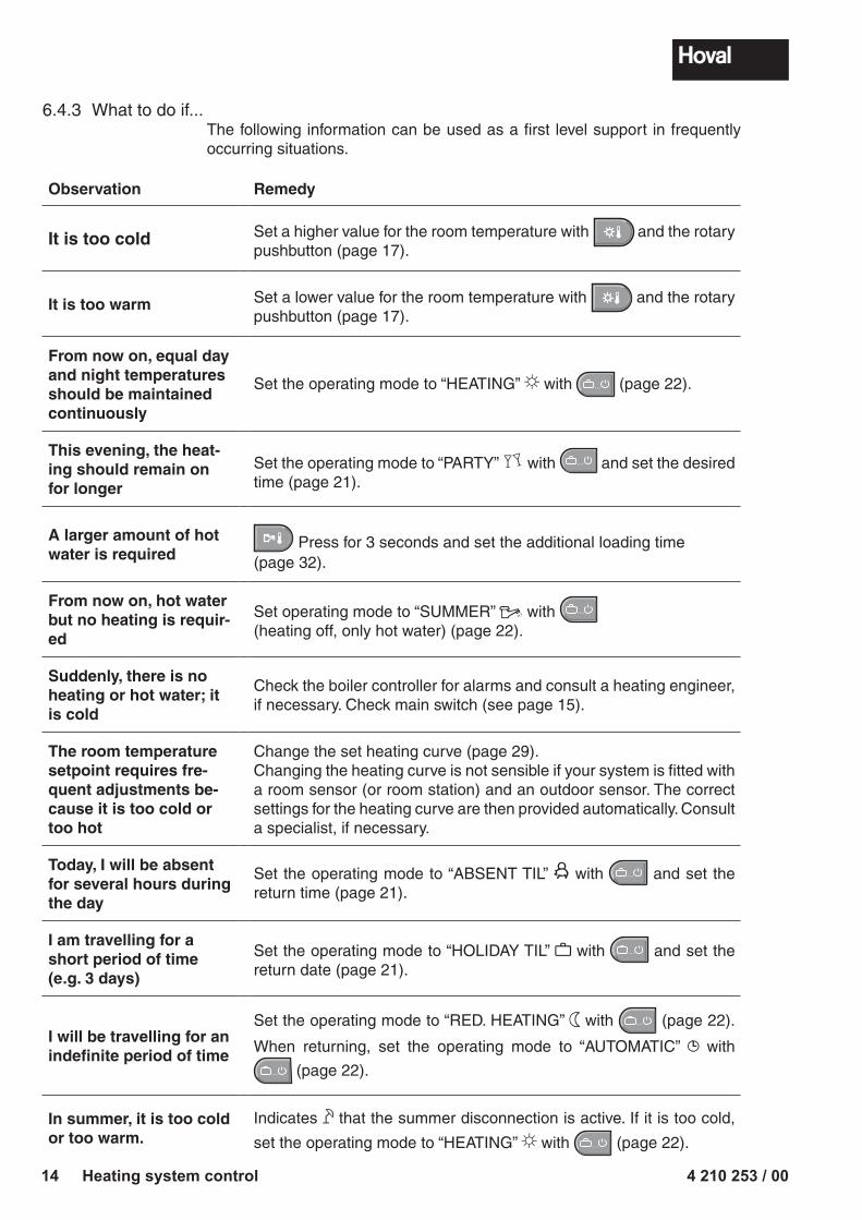
6.4.3 What to do if...The following information can be used as a first level support in frequently occurring situations.
Observation Remedy
It is too cold Set a higher value for the room temperature with and the rotary pushbutton (page 17).
It is too warm Set a lower value for the room temperature with and the rotary pushbutton (page 17).
From now on, equal day and night temperatures should be maintained continuously
Set the operating mode to “HEATING” with � � � (page 22).
This evening, the heat-ing should remain on for longer
Set the operating mode to “PARTY” with � � � and set the desired time (page 21).
A larger amount of hot water is required
Press for 3 seconds and set the additional loading time(page 32).
From now on, hot water but no heating is requir-ed
Set operating mode to “SUMMER” with � � �
(heating off, only hot water) (page 22).
Suddenly, there is no heating or hot water; it is cold
Check the boiler controller for alarms and consult a heating engineer, if necessary. Check main switch (see page 15).
The room temperatu re setpoint requires fre-quent adjustments be-cause it is too cold or too hot
Change the set heating curve (page 29).Changing the heating curve is not sensible if your system is fitted with a room sensor (or room station) and an outdoor sensor. The correct settings for the heating curve are then provided automatically. Consult a specialist, if necessary.
Today, I will be absent for several hours during the day
Set the operating mode to “ABSENT TIL” with � � � and set the return time (page 21).
I am travelling for a short period of time (e.g. 3 days)
Set the operating mode to “HOLIDAY TIL” with � � � and set the return date (page 21).
I will be travelling for an indefinite period of time
Set the operating mode to “RED. HEATING” with � � � (page 22).
When returning, set the operating mode to “AUTOMATIC” with
� � � (page 22).
In summer, it is too cold or too warm.
Indicates that the summer disconnection is active. If it is too cold,
set the operating mode to “HEATING” with � � � (page 22).
4 210 253 / 00 15Heating system control
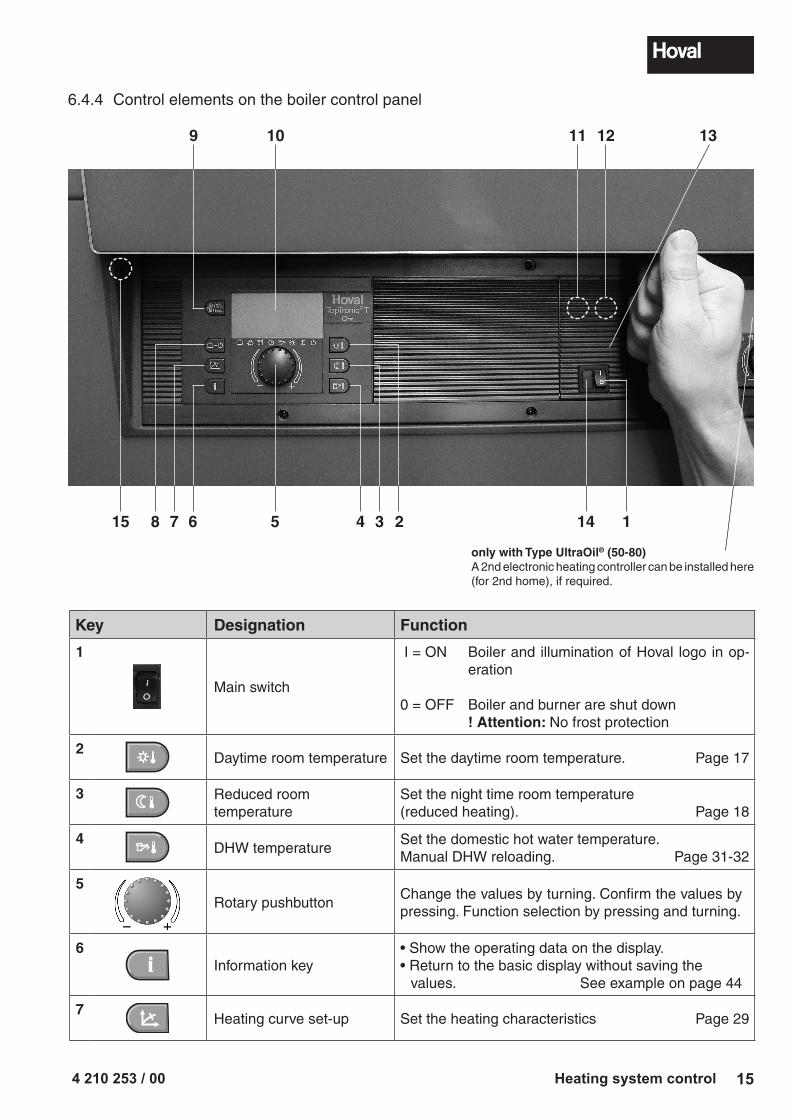
Key Designation Function
1
Main switch
I = ON Boiler and illumination of Hoval logo in op-eration
0 = OFF Boiler and burner are shut down ! Attention: No frost protection
2Daytime room temperature Set the daytime room temperature. Page 17
3 Reduced room temperature
Set the night time room temperature(reduced heating). Page 18
4DHW temperature
Set the domestic hot water temperature.Manual DHW reloading. Page 31-32
5
Rotary pushbutton
Change the values by turning. Confirm the values by pressing. Function selection by pressing and turning.
6Information key
• Show the operating data on the display.• Return to the basic display without saving the values. See example on page 44
7Heating curve set-up Set the heating characteristics Page 29
6.4.4 Control elements on the boiler control panel
15
9 10
8 67
only with Type UltraOil® (50-80)A 2nd electronic heating controller can be installed here (for 2nd home), if required.
For heating technician only or for preliminary acknowl-edgement of a maintenance prompt (see chapter 6.11.3).
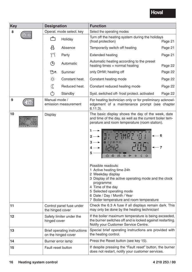
10 Display The basic display shows the day of the week, date and time of the day, as well as the current boiler tem-perature and room temperature (room station).
2
1
3
4
6
7
5
Possible readouts:1 Active heating time 24h2 Weekday display3 Display of the active operating mode and the clock
programme4 Time of the day5 Selected operating mode6 Date / Day / Month / Year7 Boiler temperature and room temperature
11 Control panel fuse underthe hinged cover
Check the 6.3 A fuse if all displays remain dark. This may only be done by the heating technician!
12 Safety limiter under thehinged cover
If the boiler maximum temperature is being exceeded, the burner switches off and is locked against restarting.Notify your Customer Service Centre.
13 Brief operating instructionson the hinged cover
Special brief operating instructions are provided with the heating control.
14 Burner error lamp Press the Reset button (see key 15).
15 Fault reset button If despite pressing the “Fault reset” button, the burner does not restart, notify your customer services.
� � �
4 210 253 / 00 17Heating system control
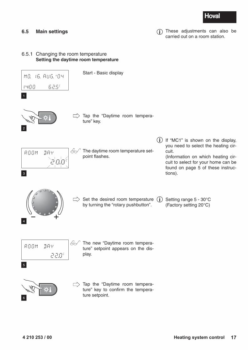
6.5 Main settings
6.5.1 Changing the room temperatureSetting the daytime room temperature
Start - Basic display
Tap the “Daytime room tempera-ture” key.
The daytime room temperature set-point flashes.
Set the desired room temperature by turning the “rotary pushbutton”.
The new “Daytime room tempera-ture” setpoint appears on the dis-play.
Tap the “Daytime room tempera-ture” key to confirm the tempera-ture setpoint.
MO. 16. AUG.'04
14:00 62.5C
ROOM DAY
20.0C
ROOM DAY
22.0C
These adjustments can also be carried out on a room station.
If “MC1” is shown on the display, you need to select the heating cir-cuit.(Information on which heating cir-cuit to select for your home can be found on page 5 of these instruc-tions).
i
i
1
2
3
4
5
6
Setting range 5 - 30°C(Factory setting 20°C)
i
4 210 253 / 0018 Heating system control
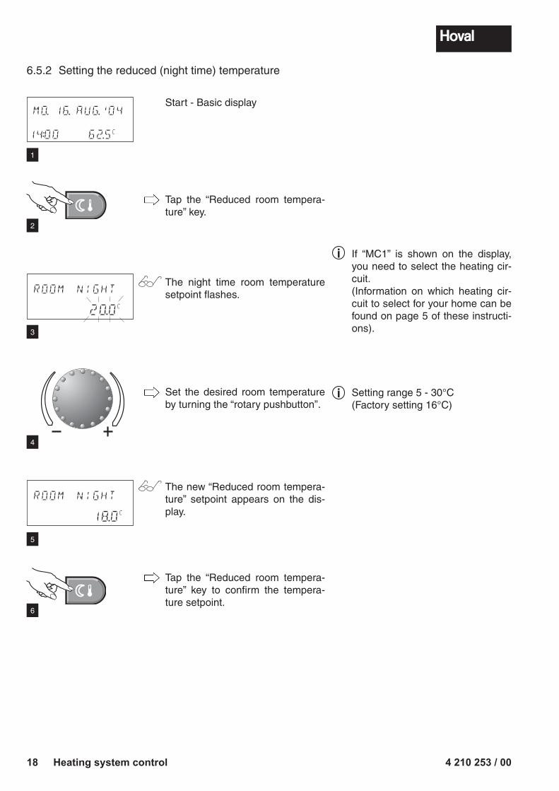
6.5.2 Setting the reduced (night time) temperature
MO. 16. AUG.'04
14:00 62.5C
ROOM NIGHT
20.0C
ROOM NIGHT
18.0C
1
2
3
4
5
6
Start - Basic display
Tap the “Reduced room tempera-ture” key.
The night time room temperature setpoint flashes.
Set the desired room temperature by turning the “rotary pushbutton”.
The new “Reduced room tempera-ture” setpoint appears on the dis-play.
Tap the “Reduced room tempera-ture” key to confirm the tempera-ture setpoint.
If “MC1” is shown on the display, you need to select the heating cir-cuit. (Information on which heating cir-cuit to select for your home can be found on page 5 of these instructi-ons).
i
Setting range 5 - 30°C(Factory setting 16°C)
i
4 210 253 / 00 19Heating system control
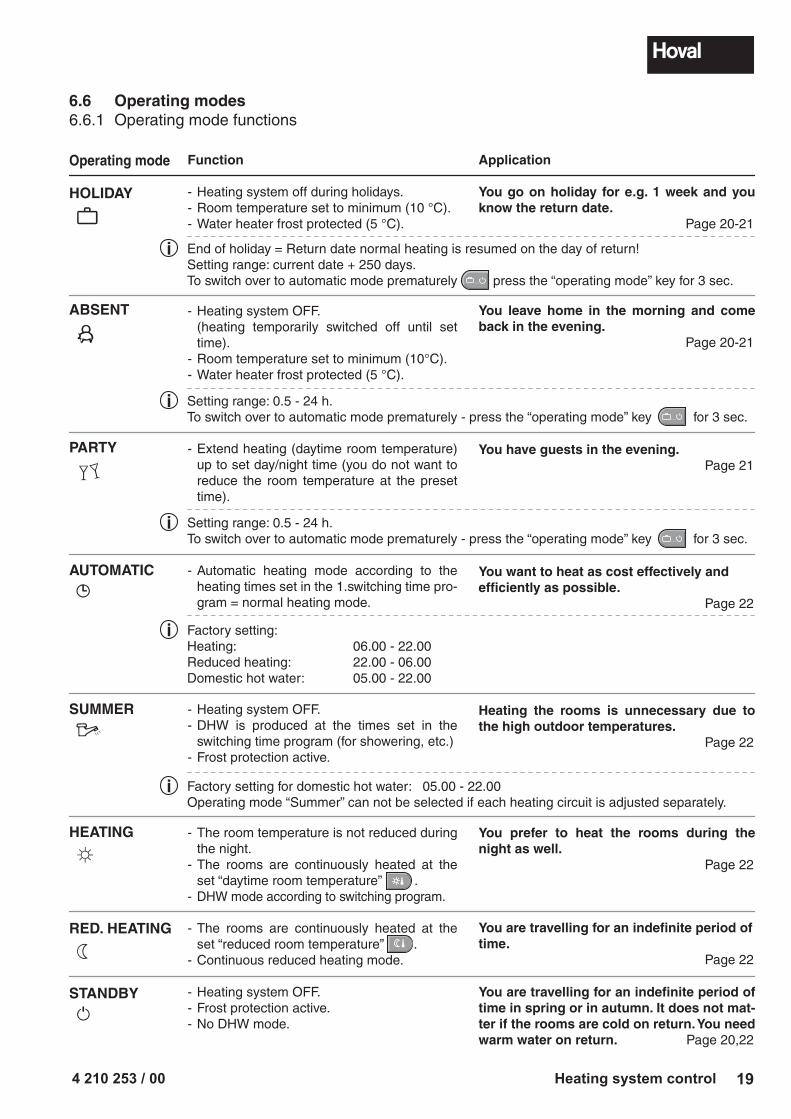
6.6 Operating modes6.6.1 Operating mode functions
Operating mode
HOLIDAY
ABSENT
PARTY
AUTOMATIC
SUMMER
HEATING
RED. HEATING
STANDBY
Function
- Heating system off during holidays.- Room temperature set to minimum (10 °C).- Water heater frost protected (5 °C).
- Heating system OFF. (heating temporarily switched off until set
time).- Room temperature set to minimum (10°C).- Water heater frost protected (5 °C).
- Extend heating (daytime room temperature) up to set day/night time (you do not want to reduce the room temperature at the preset time).
- Automatic heating mode according to the heat ing times set in the 1.switching time pro-gram = normal heating mode.
- Heating system OFF.- DHW is produced at the times set in the
switching time program (for showering, etc.)- Frost protection active.
- The room temperature is not reduced during the night.
- The rooms are continuously heated at the set “daytime room temperature” .
- DHW mode according to switching program.
- The rooms are continuously heated at the set “reduced room temperature” .
- Continuous reduced heating mode.
- Heating system OFF.- Frost protection active.- No DHW mode.
Application
You go on holiday for e.g. 1 week and you know the return date. Page 20-21
You leave home in the morning and come back in the evening. Page 20-21
You have guests in the evening. Page 21
You want to heat as cost effectively and efficiently as possible. Page 22
Heating the rooms is unnecessary due to the high outdoor temperatures. Page 22
You prefer to heat the rooms during the night as well. Page 22
You are travelling for an indefinite period of time. Page 22
You are travelling for an indefinite period of time in spring or in autumn. It does not mat-ter if the rooms are cold on return. You need warm water on return. Page 20,22
i End of holiday = Return date normal heating is resumed on the day of return!Setting range: current date + 250 days.To switch over to automatic mode prematurely � � � press the “operating mode” key for 3 sec.
i Setting range: 0.5 - 24 h.To switch over to automatic mode prematurely - press the “operating mode” key � � � for 3 sec.
i Setting range: 0.5 - 24 h.To switch over to automatic mode prematurely - press the “operating mode” key � � � for 3 sec.
i Factory setting: Heating: 06.00 - 22.00Reduced heating: 22.00 - 06.00 Domestic hot water: 05.00 - 22.00
i Factory setting for domestic hot water: 05.00 - 22.00Operating mode “Summer” can not be selected if each heating circuit is adjusted separately.
4 210 253 / 0020 Heating system control
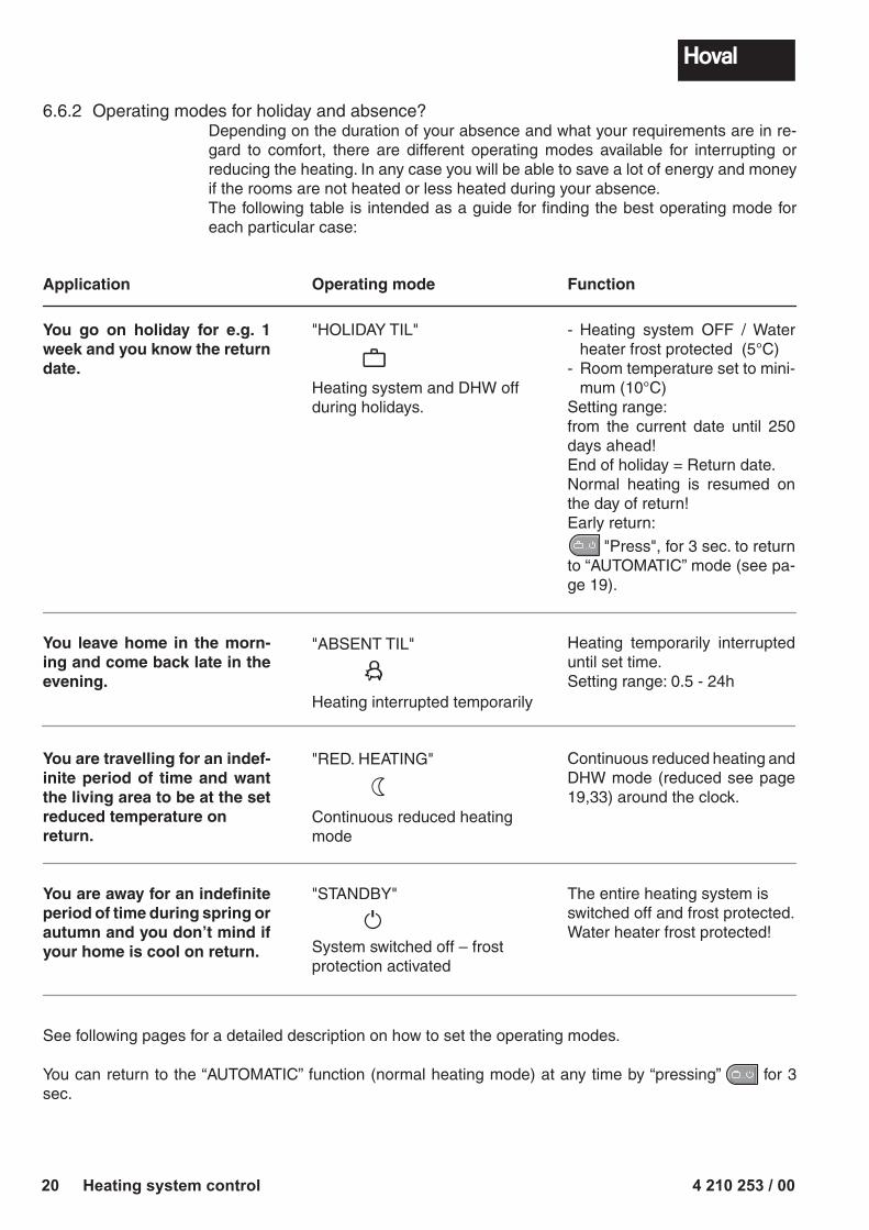
6.6.2 Operating modes for holiday and absence?Depending on the duration of your absence and what your requirements are in re-gard to comfort, there are different operating modes available for interrupting or reducing the heating. In any case you will be able to save a lot of energy and money if the rooms are not heated or less heated during your absence.The following table is intended as a guide for finding the best operating mode for each particular case:
� � �
See following pages for a detailed description on how to set the operating modes.
You can return to the “AUTOMATIC” function (normal heating mode) at any time by “pressing” � � � for 3 sec.
Application
You go on holiday for e.g. 1 week and you know the return date.
You leave home in the morn-ing and come back late in the evening.
You are travelling for an indef-inite period of time and want the living area to be at the set reduced temperature on return.
You are away for an indefinite period of time during spring or autumn and you don’t mind if your home is cool on return.
Operating mode
"HOLIDAY TIL"
Heating system and DHW off during holidays.
"ABSENT TIL"
Heating interrupted temporarily
"RED. HEATING"
Continuous reduced heating mode
"STANDBY"
System switched off – frost protection activated
Function
- Heating system OFF / Water heater frost protected (5°C)
- Room temperature set to mini-mum (10°C)
Setting range:from the current date until 250 days ahead!End of holiday = Return date. Normal heating is resumed on the day of return!Early return:
"Press", for 3 sec. to return to “AUTOMATIC” mode (see pa-ge 19).
Heating temporarily interrupted until set time.Setting range: 0.5 - 24h
Continuous reduced heating and DHW mode (reduced see page 19,33) around the clock.
The entire heating system is switched off and frost protected. Water heater frost protected!
4 210 253 / 00 21Heating system control
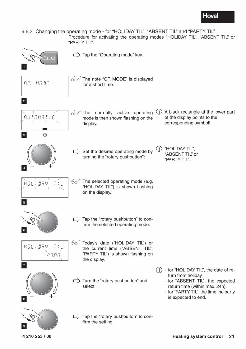
Tap the “Operating mode” key.
The note “OP. MODE” is displayed for a short time.
The currently active operating mode is then shown flashing on the display.
Set the desired operating mode by turning the “rotary pushbutton”:
The selected operating mode (e.g. “HOLIDAY TIL”) is shown flashing on the display.
Tap the “rotary pushbutton” to con-firm the selected operating mode.
Today’s date (“HOLIDAY TIL”) or the current time (“ABSENT TIL”, “PARTY TIL”) is shown flashing on the display.
Turn the “rotary pushbutton” and select:
Tap the “rotary pushbutton” to con-firm the setting.
6.6.3 Changing the operating mode - for “HOLIDAY TIL”, “ABSENT TIL” and “PARTY TIL”Procedure for activating the operating modes “HOLIDAY TIL”, “ABSENT TIL” or “PARTY TIL”.
OP. MODE
AUTOMATIC
HOLIDAY TIL
HOLIDAY TIL
27.08
� � �
1
2
3
4
5
6
A black rectangle at the lower part of the display points to the corresponding symbol!
i
7
8
9
- for “HOLIDAY TIL”, the date of re-turn from holiday.
- for “ABSENT TIL”, the expected return time (within max. 24h).
- for “PARTY TIL”, the time the party is expected to end.
i
“HOLIDAY TIL”,“ABSENT TIL” or “PARTY TIL”.
i
4 210 253 / 0022 Heating system control
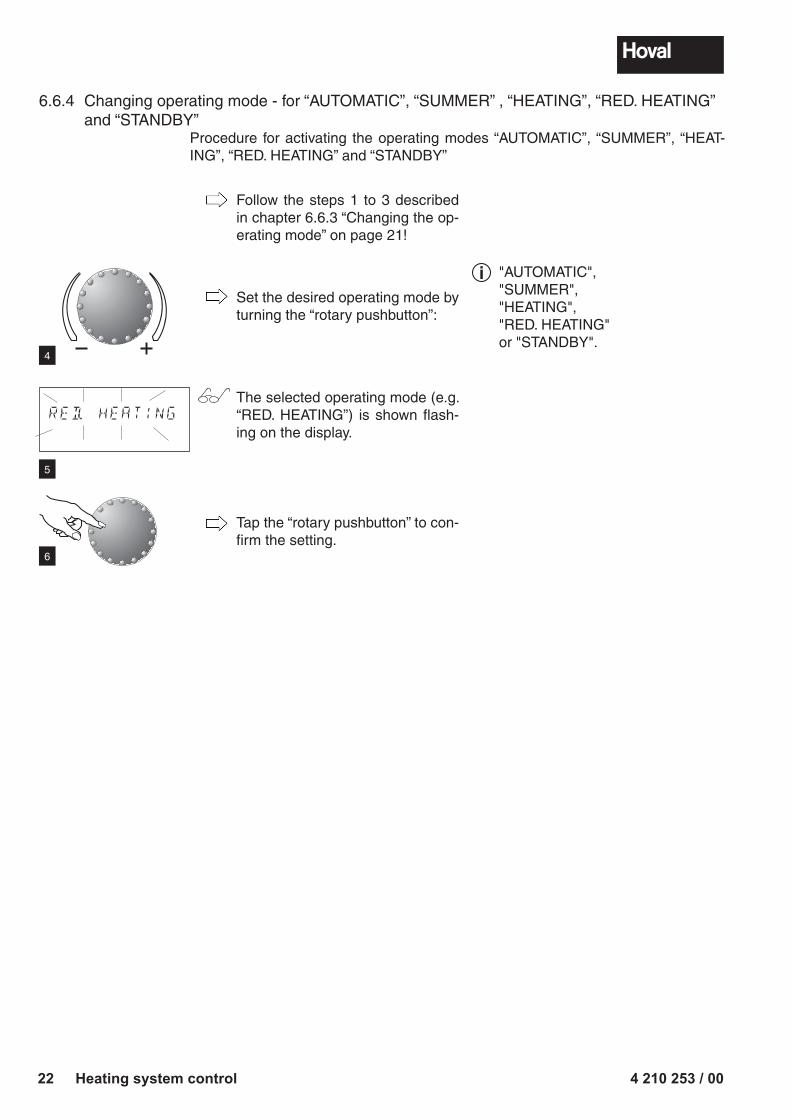
6.6.4 Changing operating mode - for “AUTOMATIC”, “SUMMER” , “HEATING”, “RED. HEATING” and “STANDBY”
Procedure for activating the operating modes “AUTOMATIC”, “SUMMER”, “HEAT-ING”, “RED. HEATING” and “STANDBY”
Follow the steps 1 to 3 described in chapter 6.6.3 “Changing the op-erating mode” on page 21!
Set the desired operating mode by turning the “rotary pushbutton”:
The selected operating mode (e.g. “RED. HEATING”) is shown flash-ing on the display.
Tap the “rotary pushbutton” to con-firm the setting.
RED. HEATING
4
5
6
"AUTOMATIC", "SUMMER", "HEATING", "RED. HEATING" or "STANDBY".
i
4 210 253 / 00 23Heating system control
... pro Tag 1 Heizzyklus!
... pro Tag 2 Heizzyklen!
... pro Tag 3 Heizzyklen!
... pro Tag 1 Heizzyklus!
... pro Tag 2 Heizzyklen!
... pro Tag 3 Heizzyklen!
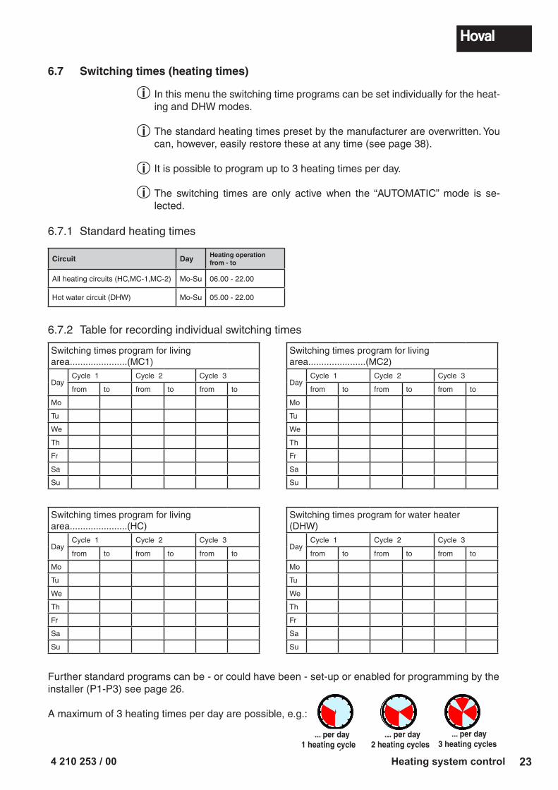
6.7 Switching times (heating times)
In this menu the switching time programs can be set individually for the heat-ing and DHW modes.
The standard heating times preset by the manufacturer are overwritten. You can, however, easily restore these at any time (see page 38).
It is possible to program up to 3 heating times per day.
The switching times are only active when the “AUTOMATIC” mode is se-lected.
6.7.1 Standard heating times
Circuit Day Heating operation from - to
All heating circuits (HC,MC-1,MC-2) Mo-Su 06.00 - 22.00
Hot water circuit (DHW) Mo-Su 05.00 - 22.00
Further standard programs can be - or could have been - set-up or enabled for programming by the installer (P1-P3) see page 26.
A maximum of 3 heating times per day are possible, e.g.:
6.7.2 Table for recording individual switching times
Switching times program for living area......................(MC1)
DayCycle 1 Cycle 2 Cycle 3
from to from to from to
Mo
Tu
We
Th
Fr
Sa
Su
Switching times program for living area......................(MC2)
DayCycle 1 Cycle 2 Cycle 3
from to from to from to
Mo
Tu
We
Th
Fr
Sa
Su
Switching times program for living area......................(HC)
DayCycle 1 Cycle 2 Cycle 3
from to from to from to
Mo
Tu
We
Th
Fr
Sa
Su
Switching times program for water heater (DHW)
DayCycle 1 Cycle 2 Cycle 3
from to from to from to
Mo
Tu
We
Th
Fr
Sa
Su
i
i
i
i
... per day1 heating cycle
... per day2 heating cycles
... per day3 heating cycles
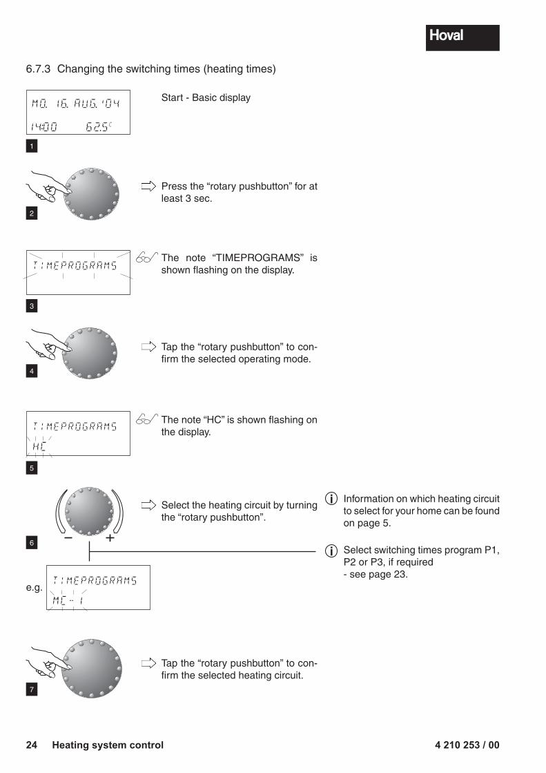
4 210 253 / 0024 Heating system control
Start - Basic display
Press the “rotary pushbutton” for at least 3 sec.
The note “TIMEPROGRAMS” is shown flashing on the display.
Tap the “rotary pushbutton” to con-firm the selected operating mode.
The note “HC” is shown flashing on the display.
Select the heating circuit by turning the “rotary pushbutton”.
Tap the “rotary pushbutton” to con-firm the selected heating circuit.
MO. 16. AUG.'04
14:00 62.5C
TIMEPROGRAMS
TIMEPROGRAMS
HC
TIMEPROGRAMS
MC-1
e.g.
1
2
3
4
5
6
Information on which heating circuit to select for your home can be found on page 5.
i
7
Select switching times program P1, P2 or P3, if required - see page 23.
i
6.7.3 Changing the switching times (heating times)
4 210 253 / 00 25Heating system control
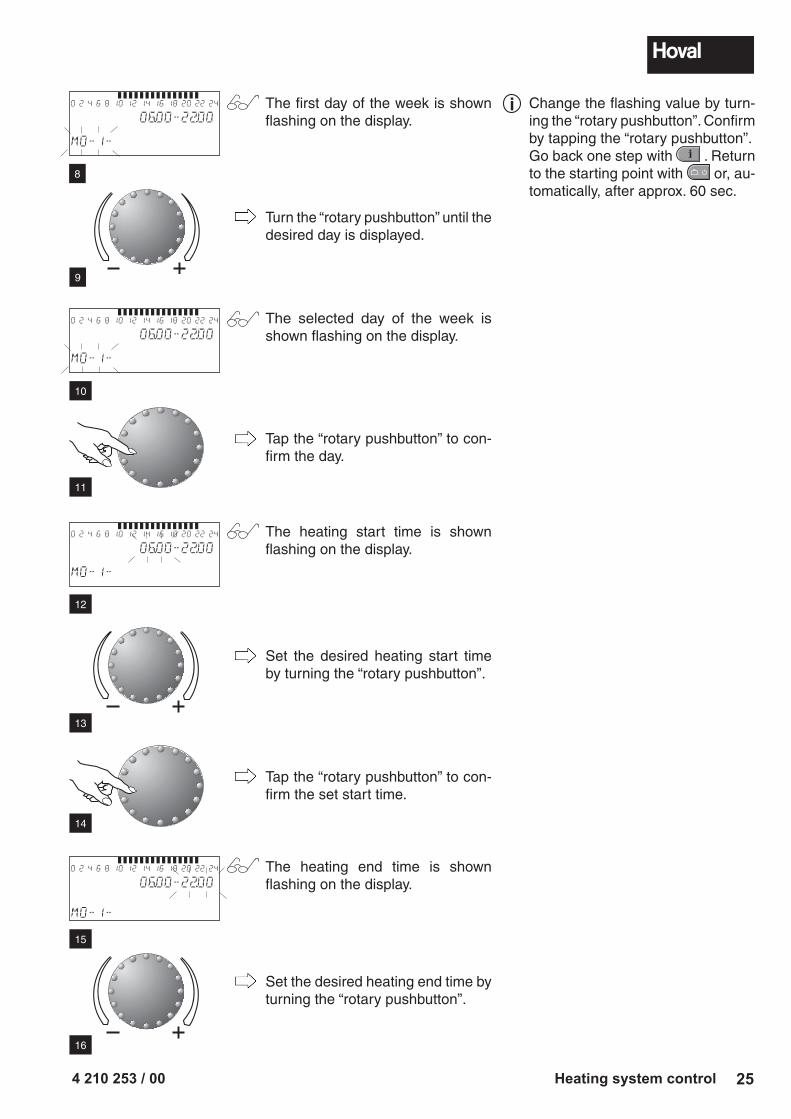
0 2 4 6 8 10 12 14 16 18 20 22 24
06.00-22.00
MO-1-
0 2 4 6 8 10 12 14 16 18 20 22 24
06.00-22.00
MO-1-
The first day of the week is shown flashing on the display.
Turn the “rotary pushbutton” until the desired day is displayed.
The selected day of the week is shown flashing on the display.
Tap the “rotary pushbutton” to con-firm the day.
The heating start time is shown flashing on the display.
Set the desired heating start time by turning the “rotary pushbutton”.
Tap the “rotary pushbutton” to con-firm the set start time.
The heating end time is shown flashing on the display.
Set the desired heating end time by turning the “rotary pushbutton”.
0 2 4 6 8 10 12 14 16 18 20 22 24
06.00-22.00
MO-1-
8
Change the flashing value by turn-ing the “rotary pushbutton”. Confirm by tapping the “rotary pushbutton”.Go back one step with . Return to the starting point with � � � or, au-tomatically, after approx. 60 sec.
i
9
0 2 4 6 8 10 12 14 16 18 20 22 24
06.00-22.00
MO-1-
10
11
12
13
14
15
16
4 210 253 / 0026 Heating system control
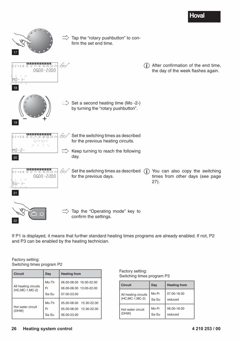
If P1 is displayed, it means that further standard heating times programs are already enabled. If not, P2 and P3 can be enabled by the heating technician.
Circuit Day Heating from
All heating circuits(HC,MC-1,MC-2)
Mo-Th
Fr
Sa-Su
06.00-08.00 16.00-22.00
06.00-08.00 13.00-22.00
07.00-23.00
Hot water circuit(DHW)
Mo-Th
Fr
Sa-Su
05.00-08.00 15.30-22.00
05.00-08.00 12.30-22.00
06.00-23.00
Circuit Day Heating from
All heating circuits (HC,MC-1,MC-2)
Mo-Fr
Sa-Su
07.00-18.00
reduced
Hot water circuit(DHW)
Mo-Fr
Sa-Su
06.00-18.00
reduced
Factory setting:Switching times program P2
Factory setting:Switching times program P3
0 2 4 6 8 10 12 14 16 18 20 22 24
06.00-22.00
SU-1-
� � �
0 2 4 6 8 10 12 14 16 18 20 22 24
-.---.--
MO-2-
Tap the “rotary pushbutton” to con-firm the set end time.
Set a second heating time (Mo -2-) by turning the “rotary pushbutton”.
Set the switching times as described for the previous heating circuits.
Set the switching times as described for the previous days.
Tap the “Operating mode” key to confirm the settings.
0 2 4 6 8 10 12 14 16 18 20 22 24
06.00-22.00
MO-1-
17
After confirmation of the end time, the day of the week flashes again.
i
18
19
Keep turning to reach the following day.20
21
You can also copy the switching times from other days (see page 27).
i
22
4 210 253 / 00 27Heating system control
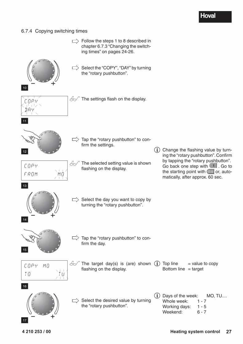
6.7.4 Copying switching times
COPY
DAY
Follow the steps 1 to 8 described in chapter 6.7.3 “Changing the switch-ing times” on pages 24-26.
Select the “COPY”, “DAY” by turning the “rotary pushbutton”.
The settings flash on the display.
Tap the “rotary pushbutton” to con-firm the settings.
The selected setting value is shown flashing on the display.
Select the day you want to copy by turning the “rotary pushbutton”.
Tap the “rotary pushbutton” to con-firm the day.
The target day(s) is (are) shown flashing on the display.
Select the desired value by turning the “rotary pushbutton”.
COPY
FROM MO
COPY MO
TO TU
10
11
12
13
14
15
16
Change the flashing value by turn-ing the “rotary pushbutton”. Confirm by tapping the “rotary pushbutton”.Go back one step with . Go to the starting point with � � � or, auto-matically, after approx. 60 sec.
i
Top line = value to copyBottom line = target
i
Days of the week: MO, TU....Whole week: 1 - 7Working days: 1 - 5Weekend: 6 - 7
i
17
4 210 253 / 0028 Heating system control
� � �
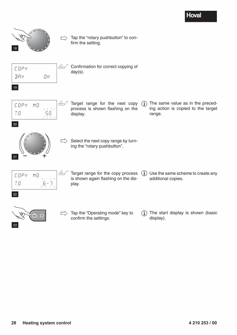
Tap the “rotary pushbutton” to con-firm the setting.
Confirmation for correct copying of day(s).
Target range for the next copy process is shown flashing on the display.
Select the next copy range by turn-ing the “rotary pushbutton”.
Target range for the copy process is shown again flashing on the dis-play.
Tap the “Operating mode” key to confirm the settings.
COPY
DAY OK
COPY MO
TO 6-7
COPY MO
TO 50
18
19
20
21
22
23
The same value as in the preced-ing action is copied to the target range.
i
Use the same scheme to create any additional copies.
i
The start display is shown (basic display).
i
4 210 253 / 00 29Heating system control
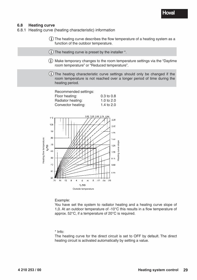
6.8 Heating curve6.8.1 Heating curve (heating characteristic) information
The heating curve describes the flow temperature of a heating system as a function of the outdoor temperature.
The heating curve is preset by the installer *.
Make temporary changes to the room temperature settings via the “Daytime room temperature” or “Reduced temperature”.
The heating characteristic curve settings should only be changed if the room temperature is not reached over a longer period of time during the heating period.
Recommended settings:Floor heating: 0.3 to 0.8Radiator heating: 1.0 to 2.0Convector heating: 1.4 to 2.0
i
i
Example:You have set the system to radiator heating and a heating curve slope of 1,0. At an outdoor temperature of -10°C this results in a flow temperature of approx. 52°C, if a temperature of 20°C is required.
i
i
* Info:The heating curve for the direct circuit is set to OFF by default. The direct heating circuit is activated automatically by setting a value.
Hea
ting
flow
tem
pera
ture
Outside temperature
Hea
ting
curv
e sl
ope
4 210 253 / 0030 Heating system control
HEAT. CURVE
HC OFF
HEAT. CURVE
HC OFF
HEAT. CURVE
HC 1.5
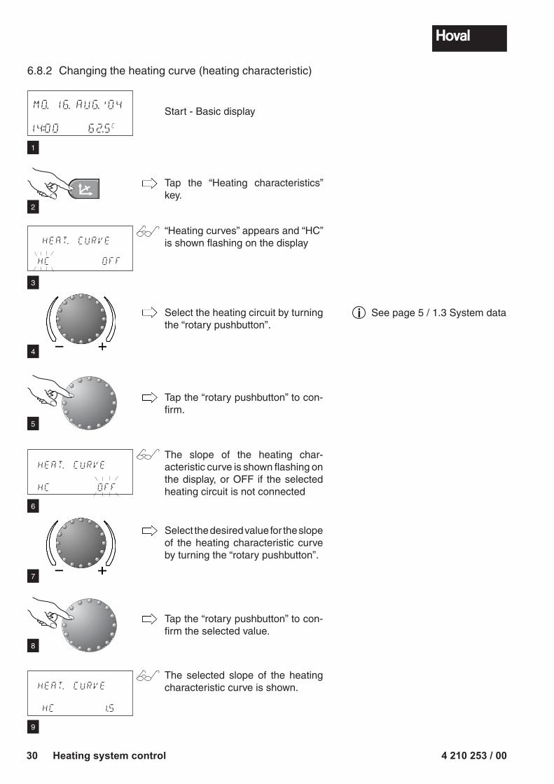
Start - Basic display
Tap the “Heating characteristics” key.
“Heating curves” appears and “HC” is shown flashing on the display
Select the heating circuit by turning the “rotary pushbutton”.
Tap the “rotary pushbutton” to con-firm.
The slope of the heating char-acteristic curve is shown flashing on the display, or OFF if the selected heating circuit is not connected
Select the desired value for the slope of the heating characteristic curve by turning the “rotary pushbutton”.
Tap the “rotary pushbutton” to con-firm the selected value.
The selected slope of the heating characteristic curve is shown.
MO. 16. AUG.'04
14:00 62.5C
6.8.2 Changing the heating curve (heating characteristic)
1
2
3
4
5
6
7
8
9
See page 5 / 1.3 System datai
4 210 253 / 00 31Heating system control
� � �
DHW
DAY 63.0C
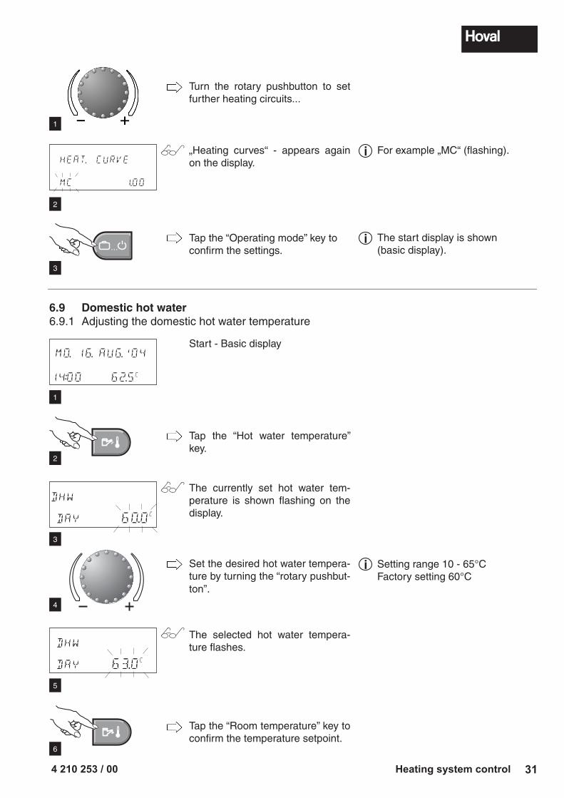
Start - Basic display
Tap the “Hot water temperature” key.
The currently set hot water tem-perature is shown flashing on the display.
Set the desired hot water tempera-ture by turning the “rotary pushbut-ton”.
The selected hot water tempera-ture flashes.
Tap the “Room temperature” key to confirm the temperature setpoint.
HEAT. CURVE
MC 1.00
Turn the rotary pushbutton to set further heating circuits...
„Heating curves“ - appears again on the display.
Tap the “Operating mode” key to confirm the settings.
6.9 Domestic hot water6.9.1 Adjusting the domestic hot water temperature
MO. 16. AUG.'04
14:00 62.5C
DHW
DAY 60.0C
The start display is shown (basic display).
i
1
2
3
4
5
6
1
2
3
Setting range 10 - 65°C Factory setting 60°C
i
For example „MC“ (flashing).i
4 210 253 / 0032 Heating system control
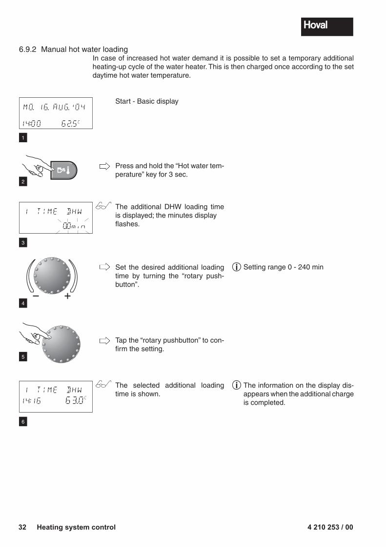
Start - Basic display
Press and hold the “Hot water tem-perature” key for 3 sec.
The additional DHW loading time is displayed; the minutes display flashes.
Set the desired additional loading time by turning the “rotary push-button”.
Tap the “rotary pushbutton” to con-firm the setting.
The selected additional loading time is shown.
1 TIME DHW 0.0min
6.9.2 Manual hot water loadingIn case of increased hot water demand it is possible to set a temporary additional heating-up cycle of the water heater. This is then charged once according to the set daytime hot water temperature.
1 TIME DHW
14:16 63.0C
MO. 16. AUG.'04
14:00 62.5C
4
5
6
1
2
3
Setting range 0 - 240 mini
The information on the display dis-appears when the additional charge is completed.
i
4 210 253 / 00 33Heating system control
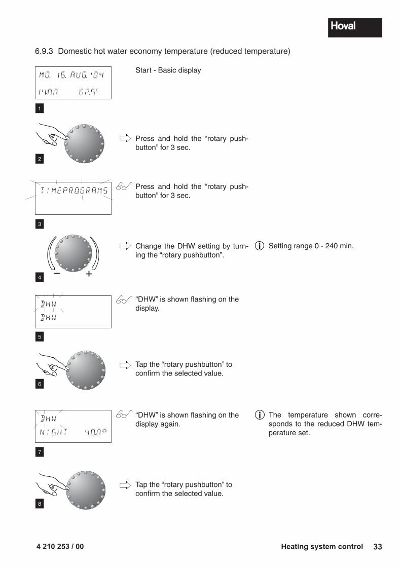
Start - Basic display
Press and hold the “rotary push-button” for 3 sec.
Press and hold the “rotary push-button” for 3 sec.
Change the DHW setting by turn-ing the “rotary pushbutton”.
“DHW” is shown flashing on the display.
Tap the “rotary pushbutton” to confirm the selected value.
“DHW” is shown flashing on the display again.
Tap the “rotary pushbutton” to confirm the selected value.
6.9.3 Domestic hot water economy temperature (reduced temperature)
TIMEPROGRAMS
DHW
DHW
DHW
NIGHT 40.0
MO. 16. AUG.'04
14:00 62.5C
Setting range 0 - 240 min.i
4
5
6
1
2
3
The temperature shown corre-sponds to the reduced DHW tem-pe rature set.
i
7
8
4 210 253 / 0034 Heating system control
� � �
DHW
NIGHT 40.0
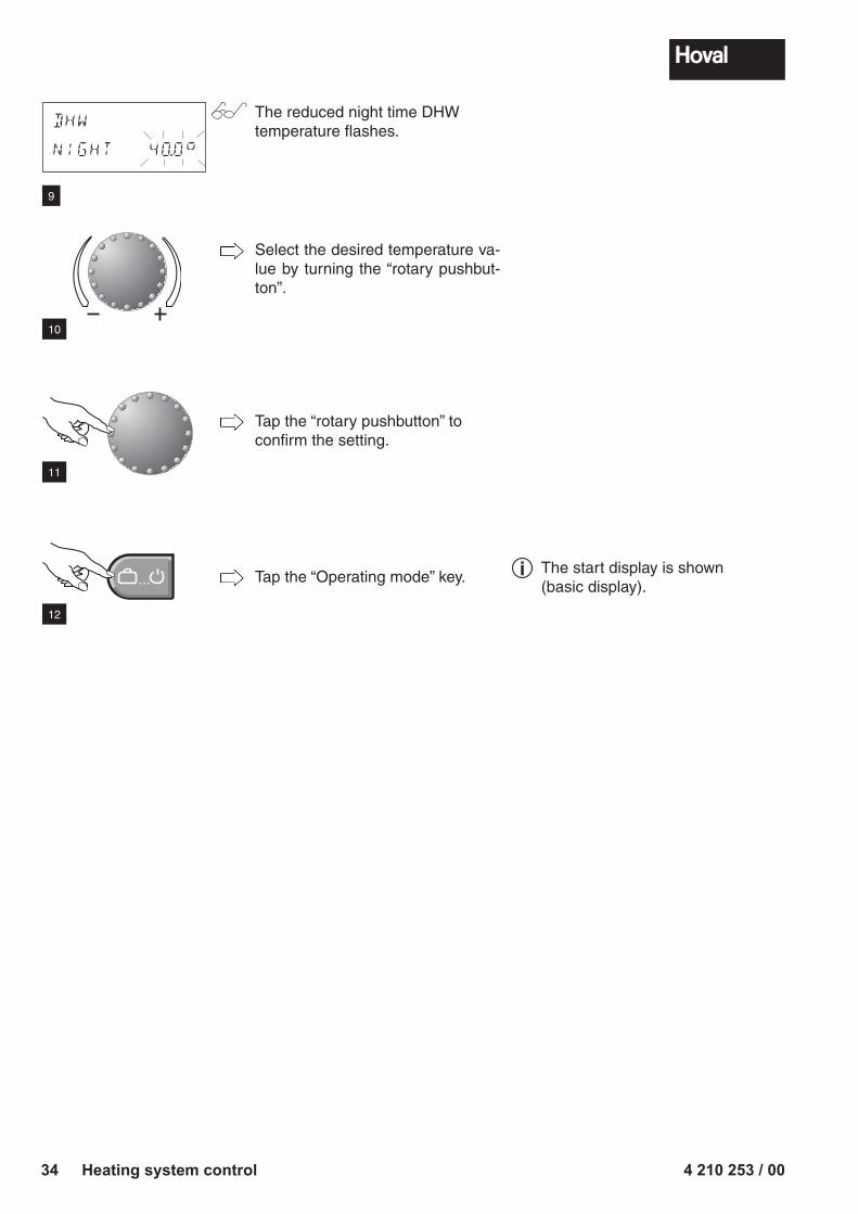
The reduced night time DHW temperature flashes.
Select the desired temperature va-lue by turning the “rotary pushbut-ton”.
Tap the “rotary pushbutton” to confirm the setting.
Tap the “Operating mode” key.
10
11
12
9
The start display is shown (basic display).
i
4 210 253 / 00 35Heating system control
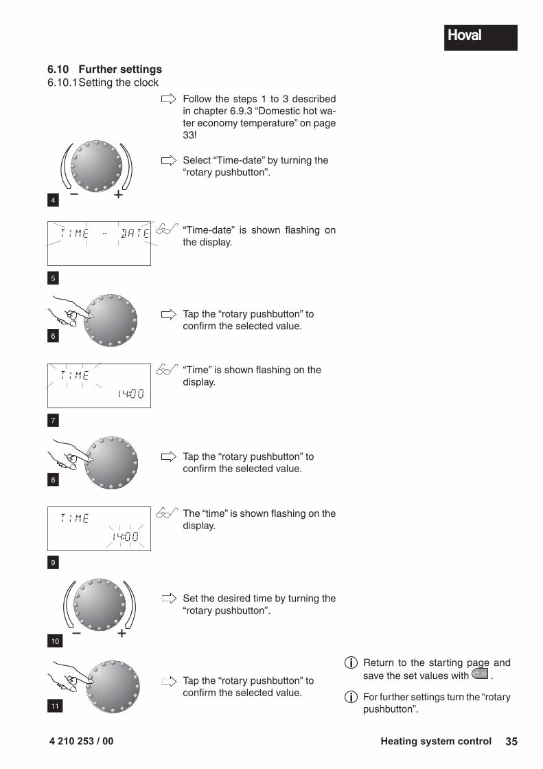
Follow the steps 1 to 3 described in chapter 6.9.3 “Domestic hot wa-ter economy temperature” on page 33!
Select “Time-date” by turning the “rotary pushbutton”.
“Time-date” is shown flashing on the display.
Tap the “rotary pushbutton” to confirm the selected value.
“Time” is shown flashing on the display.
Tap the “rotary pushbutton” to confirm the selected value.
The “time” is shown flashing on the display.
Set the desired time by turning the “rotary pushbutton”.
Tap the “rotary pushbutton” to confirm the selected value.
6.10 Further settings6.10.1 Setting the clock
TIME - DATE
TIME
14:00
TIME
14:00
4
5
6
7
8
9
10
11
Return to the starting page and save the set values with � � � .
For further settings turn the “rotary pushbutton”.
i
i
4 210 253 / 0036 Heating system control
� � �
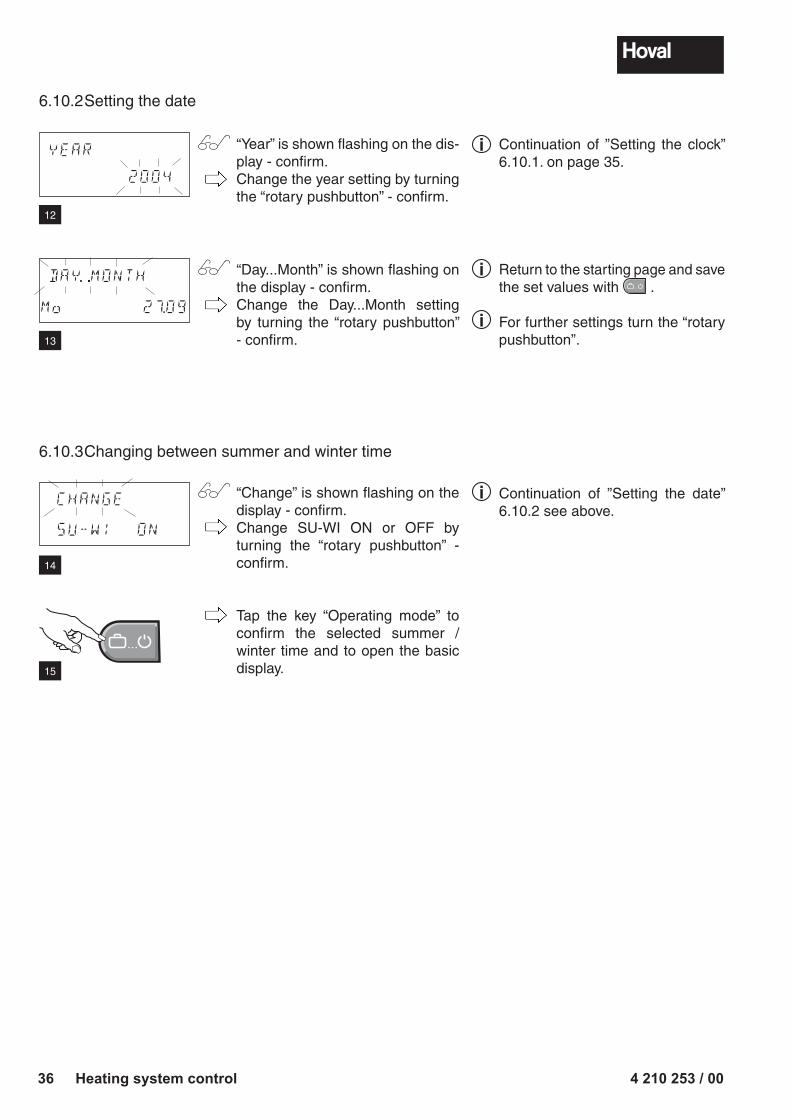
“Year” is shown flashing on the dis-play - confirm.Change the year setting by turning the “rotary pushbutton” - confirm.
“Day...Month” is shown flashing on the display - confirm.Change the Day...Month setting by turning the “rotary pushbutton” - confirm.
“Change” is shown flashing on the display - confirm.Change SU-WI ON or OFF by turning the “rotary pushbutton” - confirm.
Tap the key “Operating mode” to confirm the selected summer / winter time and to open the basic display.
6.10.2 Setting the date
YEAR
2004
DAY.. .......MONTH
Mo 27.09
CHANGE
SU-WI ON
6.10.3 Changing between summer and winter time
Return to the starting page and save the set values with � � � .
For further settings turn the “rotary pushbutton”.
i
i
12
13
14
15
Continuation of ”Setting the clock” 6.10.1. on page 35.
i
Continuation of ”Setting the date” 6.10.2 see above.
i
4 210 253 / 00 37Heating system control
� � �
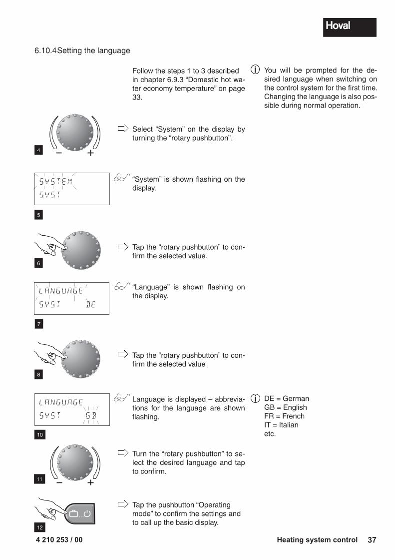
Follow the steps 1 to 3 describedin chapter 6.9.3 “Domestic hot wa-ter economy temperature” on page 33.
Select “System” on the display by turning the “rotary pushbutton”.
“System” is shown flashing on the display.
Tap the “rotary pushbutton” to con-firm the selected value.
“Language” is shown flashing on the display.
Tap the “rotary pushbutton” to con-firm the selected value
Language is displayed – abbrevia-tions for the language are shown flashing.
Turn the “rotary pushbutton” to se-lect the desired language and tap to confirm.
Tap the pushbutton “Operatingmode” to confirm the settings andto call up the basic display.
6.10.4 Setting the language
4
5
6
You will be prompted for the de-sired language when switching on the control system for the first time.Changing the language is also pos-sible during normal operation.
i
DE = GermanGB = EnglishFR = FrenchIT = Italianetc.
i
7
8
10
11
12
SYSTEM
SY5T
LANGUAGE
SYST GB
LANGUAGE
SYST DE
4 210 253 / 0038 Heating system control
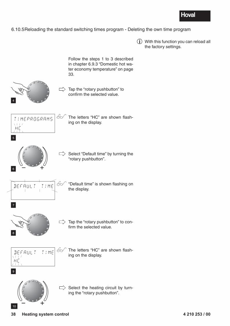
6.10.5 Reloading the standard switching times program - Deleting the own time program
Follow the steps 1 to 3 described in chapter 6.9.3 “Domestic hot wa-ter economy temperature” on page 33.
Tap the “rotary pushbutton” to confirm the selected value.
The letters “HC” are shown flash-ing on the display.
Select “Default time” by turning the “rotary pushbutton”.
“Default time” is shown flashing on the display.
Tap the “rotary pushbutton” to con-firm the selected value.
The letters “HC” are shown flash-ing on the display.
Select the heating circuit by turn-ing the “rotary pushbutton”.
DEFAULT TIME
TIMEPROGRAMS
HC
DEFAULT TIME
HC
With this function you can reload all the factory settings.
i
4
5
6
7
8
9
10
4 210 253 / 00 39Heating system control
� � �
RESET
HC
RESET
OK
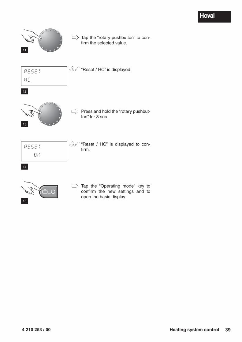
Tap the “rotary pushbutton” to con-firm the selected value.
“Reset / HC” is displayed.
Press and hold the “rotary pushbut-ton” for 3 sec.
“Reset / HC” is displayed to con-firm.
Tap the “Operating mode” key to confirm the new settings and to open the basic display.
12
13
14
15
11
4 210 253 / 0040 Heating system control
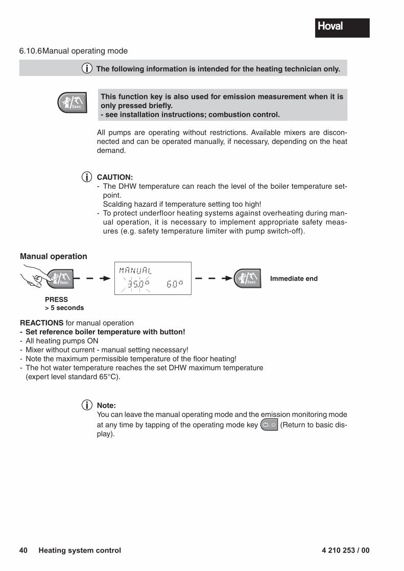
Note:You can leave the manual operating mode and the emission monitoring mode at any time by tapping of the operating mode key � � � (Return to basic dis-play).
6.10.6 Manual operating mode
The following information is intended for the heating technician only.
This function key is also used for emission measurement when it is only pressed briefly.- see installation instructions; combustion control.
All pumps are operating without restrictions. Available mixers are discon-nected and can be operated manually, if necessary, depending on the heat demand.
CAUTION:- The DHW temperature can reach the level of the boiler temperature set-
point. Scalding hazard if temperature setting too high!- To protect underfloor heating systems against overheating during man-
ual operation, it is necessary to implement appropriate safety meas-ures (e.g. safety temperature limiter with pump switch-off).
i
i
i
Manual operation
MANUAL
35.0 60Immediate end
PRESS > 5 seconds
REACTIONS for manual operation- Set reference boiler temperature with button!- All heating pumps ON- Mixer without current - manual setting necessary!- Note the maximum permissible temperature of the floor heating!- The hot water temperature reaches the set DHW maximum temperature
(expert level standard 65°C).
4 210 253 / 00 41Heating system control
FLOW
ERROR 12-0
HEAT GENER.
ERROR 30-2
BUS
ERROR 70-1
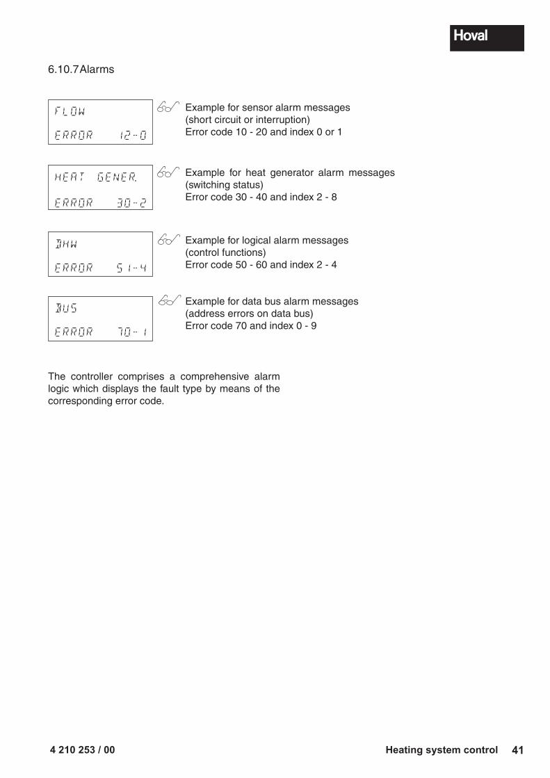
6.10.7 Alarms
Example for sensor alarm messages(short circuit or interruption)Error code 10 - 20 and index 0 or 1
Example for heat generator alarm messages (switching status)Error code 30 - 40 and index 2 - 8
Example for logical alarm messages(control functions)Error code 50 - 60 and index 2 - 4
Example for data bus alarm messages(address errors on data bus)Error code 70 and index 0 - 9
The controller comprises a comprehensive alarm logic which displays the fault type by means of the corresponding error code.
DHW
ERROR 51-4
4 210 253 / 0042 Heating system control
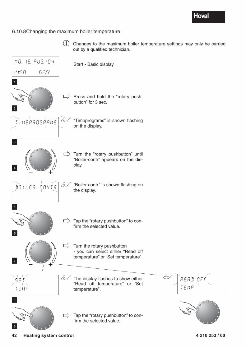
6.10.8 Changing the maximum boiler temperature
Changes to the maximum boiler temperature settings may only be carried out by a qualified technician.
i
Start - Basic display
Press and hold the “rotary push-button” for 3 sec.
“Timeprograms” is shown flashing on the display.
Turn the “rotary pushbutton” until “Boiler-contr” appears on the dis-play.
“Boiler-contr.” is shown flashing on the display.
Tap the “rotary pushbutton” to con-firm the selected value.
Turn the rotary pushbutton- you can select either “Read off temperature” or “Set temperature”.
The display flashes to show either “Read off temperature” or “Set temperature”.
Tap the “rotary pushbutton” to con-firm the selected value.
TIMEPROGRAMS
BOILER-CONTR
MO. 16. AUG.'04
14:00 62.5C
4
5
6
1
2
3
7
8
READ OFF
TEMP
SET
TEMP
9
4 210 253 / 00 43Heating system control
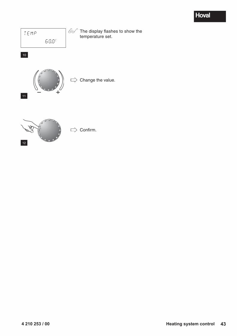
TEMP
60.0C
The display flashes to show the temperature set.
Change the value.
Confirm.
10
11
12
4 210 253 / 0044 Heating system control
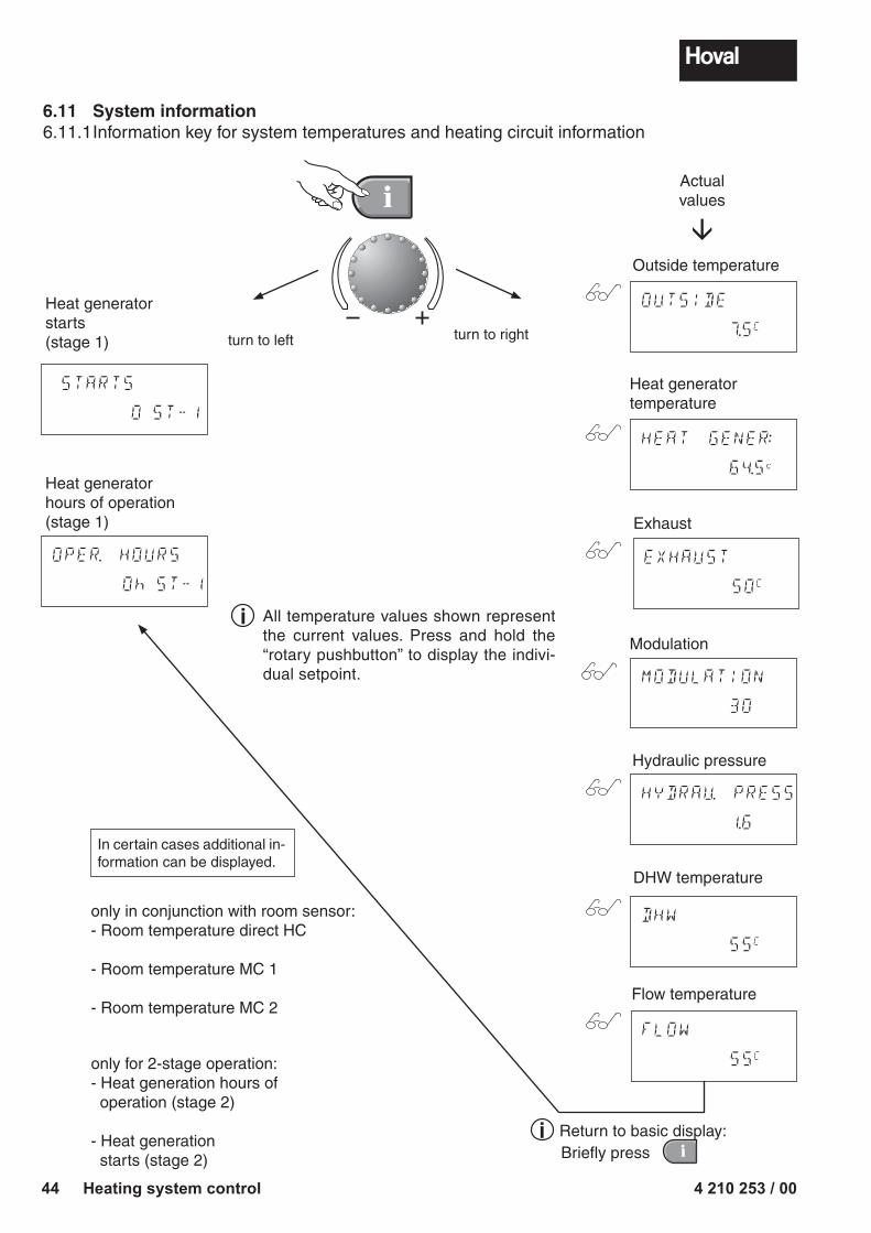
6.11 System information6.11.1 Information key for system temperatures and heating circuit information
OPER. HOURS
0h ST-1
STARTS
0 ST-1
DHW
55C
OUTSIDE
7.5C
Heat generatorhours of operation (stage 1)
Heat generatorstarts (stage 1)
Flow temperature
DHW temperature
Heat generator temperature
Outside temperature
Actual values
All temperature values shown represent the current values. Press and hold the “rotary pushbutton” to display the indivi-dual setpoint.
only for 2-stage operation:- Heat generation hours of operation (stage 2)
- Heat generation starts (stage 2)
only in conjunction with room sensor:- Room temperature direct HC
- Room temperature MC 1
- Room temperature MC 2
turn to left turn to right
i
Exhaust
EXHAUST
50C
HEAT GENER:
64.5c
MODULATION
30
Modulation
HYDRAU. PRESS
1.6
Hydraulic pressure
Return to basic display:Briefly press
FLOW
55C
i
In certain cases additional in-formation can be displayed.
Sunshade symbol:Summer disconnection active (heating switched off, DHW according to pro-gram).
6.11.3 Maintenance message
-MAINTENANCEMaintenance message (optional):If the display shows the basic display alternating with the maintenance prompt, call customer service. To temporarily suppress this message, press the Manual mode/Emission key and acknowledge according to the display "RESET SET" by pressing the PUSH & TURN button for 3 seconds.
6.11.4 Optional accessories
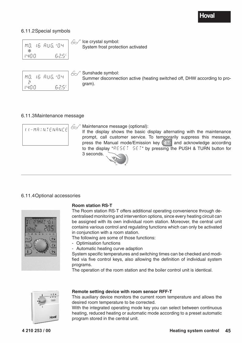
Room station RS-TThe Room station RS-T offers additional operating convenience through de-centralised monitoring and intervention options, since every heating circuit can be assigned with its own individual room station. Moreover, the central unit contains various control and regulating functions which can only be activated in conjunction with a room station.The following are some of those functions:- Optimisation functions- Automatic heating curve adaptionSystem specific temperatures and switching times can be checked and modi-fied via five control keys, also allowing the definition of individual system programs.The operation of the room station and the boiler control unit is identical.
Remote setting device with room sensor RFF-TThis auxiliary device monitors the current room temperature and allows the desired room temperature to be corrected.With the integrated operating mode key you can select between continuous heating, reduced heating or automatic mode according to a preset automatic program stored in the central unit.
4 210 253 / 0046 Oil tank and burner
7. Oil tank and burner7.1 Fuel
The boiler is only to be operated with the fuel stated on the boiler rating plate.
The UltraOil® boiler can be operated with the following types of fuel: - Low sulfur fuel oil according to DIN 51 603 / ÖNorm C 1109 - Eco low sulfur fuel oil SN 181 160-2 / 2008
7.2 Filling the oil tankWhen the oil tank is being filled, the system must always be switched off by means of the ON/OFF switch on the heating boiler. It may only be switched on again after a waiting time of about 2 hours. Filling of the heating oil tank is to be supervised by the oil supplier; we can accept no responsibility whatsoever for the oil tank being overfilled.
7.3 Burner settingYour Hoval burner was set in the factory to suit the boiler output. Fine adjustment is performed by the heating engineer or the Hoval Service when the trial operation is carried out (for the output setting, see “burner setting”, page 6).
7.4 Boiler room and supply of fresh airThe burner requires large quantities of fresh air to burn the fuel oil without produc-ing smoke. Therefore it is always essential to ensure an adequate supply of fresh air to the boiler room. Contaminated air (for example, with dust or textile fibres) rapidly causes the burning to deteriorate and can shorten the service life of the boiler. For this reason, it is desirable that the boiler room is always kept clean and free of dust and dirt. No chemicals may be stored in the boiler room, nor in the fresh air supply route to the boiler room.
7.5 Putting into service Check the water level in the heating system Check the level of the oil in the oil tank with the dip-stick Check the settings of the boiler operating elements (see from page 15) Check the oil feed to the burner (slider stop valve next to the oil feed open) Check the cut-outs on the switch-panel Turn the emergency switch to “ON” or put the plug in.
The burner can now be turned on by switching on the main switch on the heating boiler.
7.6 Taking out of serviceWhen shutting down the oil burner for a short period only, it is sufficient only to switch off the ON/OFF switch on the heating boiler. If the burner is to be shut down for a longer period, it is recommended to close the oil feed valve.
7.7 Maintenance of the burnerAn important precondition for economical operation as well as for keeping the air clean is the perfect technical condition of your firing equipment. The burner should be inspected at least once a year by a specialist. We strongly recommend you to conclude a maintenance contract.
4 210 253 / 00 47Maintenance and checks
8. Maintenance and checks
Normally, the work described in the following will be carried out by your maintenance engineer at the annual servicing. Nevertheless, you should carry out the following checks regularly throughout the year, and do the work described if necessary.
Check the water levelWhen the water pressure is too low (readable from the manometer), notify your installation engineer and/or refill with water as required.
Cleaning, descaling the water heater,safety valve water heater, taking out of service
Cleaning
Descaling the water heater
Safety valve water heater
Taking out of service
Inadequate cleaning leads not only to increased fuel con-sumption but it also shortens the service life of the boiler.
In accordance with national regulations, the heating boiler of oil-fired systems is to be cleaned by the boiler inspector.The boiler UltraOil® (16-80) is to clean and to maintain 1x per year.For further information regarding cleaning, see the Technical Infor-mation/ Installation Instructions for the UltraOil®.
In hard-water areas, the water heater and the immersion heater ele-ments should be periodically descaled in the interests of providing hot water on an economical basis.The water heater may only be descaled with chemicals, or by using wooden or plastic tools.Where the water is extremely hard, the sanitary equipment installer should be asked to report on the advisability of installing water-softening equipment.
To avoid any possibility of damage due to excessive pressure, the sanitary equipment installer should periodically check the safety valve.
When the compact heating centre or the heating boiler are standing idle for several weeks, the following work should be undertaken:clean the boiler heating surfaces carefully. As a specialist, your boiler inspector will be pleased to advise you.When there is risk of frost, have the system emptied in accordance with the instructions given by the heating system installer, or have antifreeze added to the system in accordance with the installer’s instructions.Your system is fitted with an electronic heat control which guarantees a minimum room temperature of 5°C when frost threatens, provided the system is switched on.
4 210 253 / 0048 Maintenance and checks
Recommendations:
Water heater inspectionThe water heater should be inspected every three years. You can take out a corresponding service contract with the supplier.
Oil tank inspectionIt is legally required that the oil tank must be inspected and cleaned. You should approach a specialist oil tank inspection company to carry this out.Recommendation: check whether your third party liability insurance covers all damage which might arise in the event of an escape of oil.
Boiler inspection!After 8 to 10 years in operation, a general inspection by the Hoval Service is recommended.
4 210 253 / 00 49Check list in case of faults
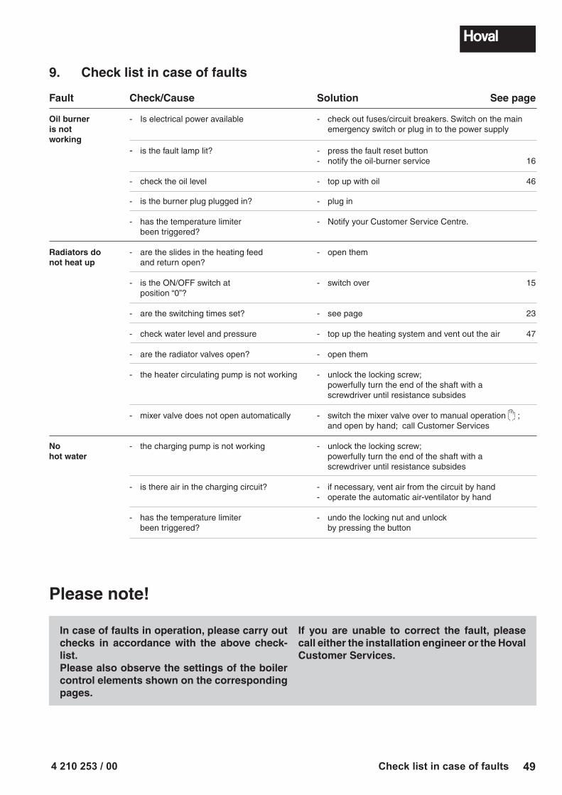
Fault Check/Cause Solution See page
Oil burner - Is electrical power available - check out fuses/circuit breakers. Switch on the main is not emergency switch or plug in to the power supplyworking - is the fault lamp lit? - press the fault reset button - notify the oil-burner service 16
- check the oil level - top up with oil 46
- is the burner plug plugged in? - plug in
- has the temperature limiter - Notify your Customer Service Centre. been triggered?
Radiators do - are the slides in the heating feed - open themnot heat up and return open?
- is the ON/OFF switch at - switch over 15 position “0”?
- are the switching times set? - see page 23 - check water level and pressure - top up the heating system and vent out the air 47
- are the radiator valves open? - open them
- the heater circulating pump is not working - unlock the locking screw; powerfully turn the end of the shaft with a screwdriver until resistance subsides
- mixer valve does not open automatically - switch the mixer valve over to manual operation ; and open by hand; call Customer Services
No - the charging pump is not working - unlock the locking screw; hot water powerfully turn the end of the shaft with a screwdriver until resistance subsides
- is there air in the charging circuit? - if necessary, vent air from the circuit by hand - operate the automatic air-ventilator by hand
- has the temperature limiter - undo the locking nut and unlock been triggered? by pressing the button
Please note!
If you are unable to correct the fault, please call either the installation engineer or the Hoval Customer Services.
In case of faults in operation, please carry out checks in accordance with the above check-list.Please also observe the settings of the boiler control elements shown on the corresponding pages.
9. Check list in case of faults
4 210 253 / 0050 Saving energy
10. This is how you can save energy
Room temperatures and operating times of the heating system have a decisive influence on the fuel consumption.
1°C reduction in the room temperature setting leads to an economy in fuel consumption of up to 6%. Therefore, please take note of the following tips:• Avoid setting room temperatures above 20°C and adjust your heating system ac-
cordingly.• It is worth turning off the radiators in unused rooms, provided there is no risk of frost
and no damage caused by moisture either to the building fabric or its furnishings is to be expected.
• In the main living rooms, there is frequently heat gain due to body warmth, televi-sions, fireplaces and also sunshine. These cannot be compensated by a weather-dependent regulatory system. It may be worth installing a remote control with an integrated room sensor or fitting thermostats to the radiators in these rooms.
When it is draughty in the house, it is not merely unpleasant; it indicates at the same time that heating energy is being wasted.
You therefore save fuel if you...• keep windows and doors closed in winter.• close chimney dampers when the fire is out.• only operate kitchen and bathroom fans when it is necessary to remove moisture
and odours.• only ventilate briefly, but frequently.• seal doors and windows, to prevent continuous leakage loss.
Insulation helps to keep in valuable warmth.
Take advantage of all these possibilities and...• close window and door shutters at night.• make sure that heating pipes and hot water pipes in unheated rooms are properly
insulated.
As low a radiator temperature as possible will prevent unnecessary heat losses.
For this reason, the radiator must always be enabled to give its heat up to the room without hindrance. You should therefore avoid:• radiator coverings• window-sills which obstruct heat flow because the outlets are covered.
Heating the hot water too offers opportunities for saving.
• The hot water temperature should be set as low as possible. Experiment to find out the lowest temperature at which there is still enough hot water available.
• If your system includes a hot water circulating pump, it is worth shutting this down at night by means of a time-switch.
ENERGY
4 210 253 / 00 51Service / sales
11. Hoval Service / sales program
There are many advantages in favour of having a service agreement
• Your heating system will always be optimally adjusted – this saves heating costs and helps preserve the environment.
• A high level of operational reliability, as in the course of servicing early warning of possible faults may be recognised and corrected.
• Optimum settings of your system and the regular maintenance will together guar-antee a longer service life for your system.
• The advantageous all-in price.
The Hoval specialists are well-equipped and will give you good and reliable service.
When you give us an order, please call the regional Service Controller, who works in close co-operation with the service engineers in the area.The service call can then be made without delay.
You will find we have product ranges which offer you possibilities in all sizes of new builds and renovated buildings.
Modern Hoval system engineering with a guaranteed future includes:
Heat generation systems
Compact heating centres for oil firing, heating boilers for oil- and wood-firing, burn-ers, solar energy production systems (collectors) and heat-pumps for making use of geothermal heat or heat generated by wind and water.
Heat distribution systems and buildings services
Water heaters (boilers), radiators, heating walls, convectors, low-temperature radia-tors, heating and ventilation regulators, circulation pumps and heating oil tanks of both plastic and concrete.