(2015), and ASTM D 4935-99 (1999) are well known. MIL-STD-285 is the first stan-
dard related to EM shielding. It is not so accurate and repeatable due to the presence of
discontinuities between the sample and the measuring enclosure, especially for small-
sized samples. The frequency range is also limited (up to 400 MHz). To overcome
these issues related with the standard, some modifications were made by
Perumalraj et al. (2010). The IEEE-STD 299 (97) standard is suitable for large enclo-
sures (especially, >2 m) and it has a wide range of working frequency (expandable
from 9 kHz–18 GHz to 50 Hz–100 GHz). DIN-VG-95373-15 is suitable for measur-
ing EM shielding behavior of small- to medium-sized enclosures between 30 and
200 MHz frequency ranges. ASTM D 4935-99 is a very commonly used standard
for EM shielding textiles. It has a large frequency range (between 30 MHz and
1.5 GHz). There are several parameters limiting the usage of higher frequencies such
as sample thickness (which should be lower than 1/100 of wavelength), requirement of
device calibration, and uniform sample-antenna distance (Badic and Marinescu,
2002). Different test methods were investigated by using these standards. These are
the open-field test, coaxial transmission line test, shielded box test, and shielded room
tests. The open-field test method requires a large open field (�30�30 m2) and there
should not be any metallic or conductive object between the sample and the receiving
antenna. The shielded box test is only suitable for materials in near-field conditions
and its measurement range is limited (i.e., up to 500 MHz). Furthermore, inadequate
contact between the sample and the shielded box may affect the repeatability and reli-
ability of results. The shielded room test is found to improve the reliability of the
shielded box test. It is possible to obtain repeatable results by using the shielded room
test, especially in externally disturbing conditions. Among these test methods, the
coaxial transmission line test is the most common one due to its suitability to measure
small-sized, flat, and thin conductive samples in an extended range of frequency
( Jagatheesan et al., 2015).
13.3.3 Materials used in EM shielding
The materials for shielding should have high electric conductivity and magnetic per-
meability. To this end, electrically conductive materials, conductive composite mate-
rials, ferromagnetic materials, or magnetic composite materials are used commonly in
EM shielding applications. Conductive fillers such as metals, alloys, and carbona-
ceous materials (carbon black—CB, graphite, etc.) are common components in con-
ductive composite materials. These materials can be used as a filler in the composite as
well as shielding structure by itself (Faraday cage). The addition of conductive filler
into the composite also increases its thermal conductivity. This reduces the chances of
thermal and chemical degradation during processing and improves its shelf life. Dif-
ferent materials used in EM shielding are listed as follows:
310 Engineering of High-Performance Textiles
l Ferrite (Fe3O4) and other magnetic materials (Rubacha and Zieba, 2007; Morari et al., 2011).l Nonferromagnetic materials (metals, alloys, etc.).l Carbonaceous materials (graphite, graphene, CNTs, carbon nanocoils (CNCs), etc.).l Conductive polymers.
Ferromagnetic materials, such as Fe, Ni, Co, Fe3O4, MnFe2O4, NiFe2O4, etc., can
show a spontaneous magnetization under an EM field. These materials have a high
level of magnetic permeability, which helps in storing/attenuating strong magnetic
fields than many other metals.
Metals are the primary candidates for EM shielding due to their high electrical con-
ductivity. They can be used as sheet, coated sheet, or wire [Cu, Ag, Au, Ni wires
(Rubacha and Zieba, 2006; Sonehara et al., 2009), Ni (Sonehara et al., 2008), or Zn
(Koprowska et al., 2008) coated-wires, etc.]. For high EM shielding effectiveness,
the reflectionmechanism is often adopted due to the presence of free electrons inmetal
structure. Metal coating can be applied on bulk materials, fibers, or particles, but coat-
ings tend to suffer from their poor wear or scratch resistance (Chung, 2001). Further-
more, metals have certain shortcomings such as heavy weight, narrow breaking
tolerance, oxidization in atmosphere and not being usable in corrosive media.
Shyr and Shie studied the effects of conductivity, magnetic loss, and complex per-
mittivity when using blended textiles of polyester fibers (polyethylene terephthalate,
PET) with stainless steel fibers (SSF) on EMwave shielding mechanisms at EMwave
frequencies ranging from 30 to 1500 MHz. Their results showed that the EM interfer-
ence shielding of the SSF/PET textiles show an absorption-dominant mechanism,
which is attributed to the dielectric loss and the magnetic loss at a lower frequency,
and to the magnetic loss at a higher frequency, respectively (Shyr and Shie, 2012).
Carbonaceous materials, such as CB, graphite, CNTs, CNCs, and graphite
nanosheets, exhibit high EM shielding effectiveness due to their thermally activated
carrier hopping associated with defect states. In practice, carbon-based plastic com-
posite materials can be used as shields. Carbonaceous materials used in those compos-
ites are graphite (Morari et al., 2011), carbon nanotubes (CNT) (Park et al., 2010;
Al-Saleh and Sundararaj, 2009), flexible and colloidal graphite (Chung, 2001), con-
tinuous carbon nanofiber (Luo and Chung, 1999), graphene (Wen et al., 2014), etc.
Ghosh and Chakrabarti (2000) produced a CB/vulcanized rubber composite with
�33 wt% CB loading. This composite showed �16 dB shielding effectiveness in
the range of 8–12 GHz. Instead of a conventional polymer, the use of a conducting
polymer as matrix for the composite improves shielding effectiveness by changing
the percolation threshold of the composite. Agnihotri et al. showed that an addition
of 0.5 wt% graphite nanoplates (GNPs) to PEDOT:PSS took the EM shielding effec-
tiveness to�30 dB. For higher amount of GNP loadings (25 wt%), the shielding
effectiveness value reached 70 dB at 0.8-mm thickness (Agnihotri et al., 2015). In
another study, 1.4-mm-thick carbon fiber composites (with very high carbon content)
showed higher than 70 dB shielding effectiveness at 8–12 GHz frequency range. The
shielding mechanism was dominated by reflection due to the larger number of con-
nected conduction paths in the sample (Rea et al., 2005).
Luo and Chung used a carbon-matrix composite with continuous carbon fibers to
improve shielding effectiveness in the frequency range from 0.3 MHz to 1.5 GHz.
Conductive textiles 311
A 2.4-mm-thick composite was found to be an excellent EM shielding material with
shielding effectiveness �124 dB, low surface impedance and high reflectivity (Luo
and Chung, 1999). Wang et al. compared EM shielding effectiveness of printed com-
posite films made of CB, graphite, and CNTs with different aspect ratios (�300). The
samples had 15 wt% of carbon fillers. CNTs with a higher aspect ratio showed better
shielding effectiveness even with the small thickness of 100 μm (Wang et al., 2009).
In another study, a 1-mm-thick MWCNT/PP composite film (7.5 vol% of MWCNT)
showed 36.4 dB EM shielding effectiveness at 12.4 GHz. With increasing thickness
and CNT content, the EM shielding effectiveness was improved. It was also observed
that absorption was the primary shielding mechanism (Al-Saleh and Sundararaj,
2009). Liang et al. achieved a 21 dB shielding efficiency from 15 wt% graphene
loaded-graphene/epoxy composites over a frequency range of 8.2–12.4 GHz (Liang
et al., 2009). To improve dipole polarization and the hopping conductivity of compos-
ites, reduced-graphene oxide (r-GO) was also used along with Fe3O4 and polystyrene
(PS). The EMI shielding effectiveness of the PS/r-GO/Fe3O4 composite was more
than 30 dB in the frequency range of 9.8–12 GHz with 2.24 vol% of graphene loading
(Chen et al., 2015). To observe high-temperature (200°C) performance, the r-GO/SiO2
composite was prepared with 20 wt% r-GO loading and�38 dB of EM shielding
effectiveness was obtained at a 8.2–12.4 GHz frequency range (Wen et al., 2014).
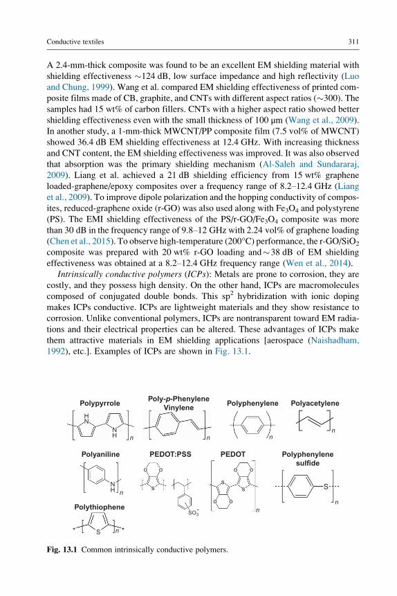
Intrinsically conductive polymers (ICPs): Metals are prone to corrosion, they are
costly, and they possess high density. On the other hand, ICPs are macromolecules
composed of conjugated double bonds. This sp2 hybridization with ionic doping
makes ICPs conductive. ICPs are lightweight materials and they show resistance to
corrosion. Unlike conventional polymers, ICPs are nontransparent toward EM radia-
tions and their electrical properties can be altered. These advantages of ICPs make
them attractive materials in EM shielding applications [aerospace (Naishadham,
1992), etc.]. Examples of ICPs are shown in Fig. 13.1.
Polypyrrole
Polyaniline
Polythiophene
S
S
SO3
NH
NH
NH
n
n
n n
n
n
n
n
ss
s
-
o
oo
ooo
**
Poly-p-PhenyleneVinylene
Polyphenylene
Polyphenylenesulfide
Polyacetylene
PEDOTPEDOT:PSS
Fig. 13.1 Common intrinsically conductive polymers.
312 Engineering of High-Performance Textiles
The major drawbacks of ICPs are their moderate mechanical properties and limited
processability. Naishadham found that multiple layers of conductive polyacetylene
(PAc) had better shielding effectiveness compared with single-layer PAc at the same
thickness (Naishadham, 1992). In another study, poly(3,4-ethylenedioxythiophene)
(PEDOT)/PET and polypyrrole (PPy)/PET composites were prepared by spray-
coating on a PET fabric. Kim et al. observed that a PPy/PET composite with 0.3
Ω*cm volume resistivity had 35 dB EM shielding effectiveness from 50 MHz to
1.5 GHz. It was also observed that PEDOT/PET samples with 3.5 Ω*cm volume
resistivity showed �14 dB shielding effectiveness at settings similar to PPy/PET
samples (Kim et al., 2003). Thermal oxidation behavior of PPy can be altered by using
different polymerization techniques. Kim et al. produced a dense structure of PPy
coating by electrochemical polymerization. Tight packing made PPy more defensive
to attack by oxygen, resulting in much better environmental stability (Kim et al., 2002;
Cetiner, 2014; Avloni et al., 2007). To improve the mechanical and shielding proper-
ties of polyaniline (PANI), PANI was coated on MWCNTs and this material was
proposed as a hybrid conductive filler in various thermoplastic matrices for making
structurally strong microwave shielding composites (Saini et al., 2009). In addition
to homopolymers of ICPs, copolymers of ICPs were also produced. For example,
Saini and Choudhary synthesized a highly conductive (12.8 S cm�1) copolymer of
aniline:2-isopropyl aniline (CP95Ip, 95:5) with high EM shielding effectiveness
values (�23.2 dB) (Saini and Choudhary, 2013; Table 13.2).
13.3.4 EM shielding designs in textiles
EM shielding textile materials can be found in the form of woven, knitted, or nonwo-
ven fabric. The major components of those fabrics are fibers and yarns. To achieve an
effective shielding behavior, these fibers or yarns should be electrically conductive.
Conductive yarns can be made by blending conductive fibers with conventional staple
fibers, twisting conductive/insulator filaments together, or conductive coating. Con-
ductive coating by using different techniques (metal plating, etc.), compounding with
conductive fillers, or just using ICPs as textile media are basic methods to create EM
shielding materials. For example, conductive metallic yarn (silver, copper, etc.) can be
wrapped with insulating textile materials to create hybrid yarns, which can be directly
integrated into woven or knitted structures (Erdumlu and Saricam, 2015; Rau et al.,
2011; Apreutesei et al., 2014).
Table 13.2 EM shielding effectiveness of different materials
Materials Frequency SE (dB) Ref.
MWCNT 15–1000 MHz 23 Wang et al. (2009)
Pani 12.4–18 GHz �27–39 Saini et al. (2009)
CP95Ip 12–18 GHz �23.2 Saini and Choudhary (2013)
Conductive textiles 313
The most common woven fabric designs include plain, twill, and satin patterns.
Hybrid yarns or metallic wires can be integrated into these designs as warp or weft
yarns. Roh et al. (2008) found that the EM shielding effectiveness of the fabric
decreased with the increase in fabric openness. Das et al. analyzed the effect of mate-
rial, yarn count, and number of layers of fabrics on the EM shielding effectiveness of
textile fabrics. According to their results, metal sheets (copper and brass) showed
much better performance than cellulose and PET sheets. With the increase in thick-
ness, yarn diameter, weight per unit area, and the number of fabric layers, EM
shielding effectiveness was also increased (Das et al., 2009). Perumalraj et al. mea-
sured the EM shield effectiveness of woven fabrics produced from copper-cotton
(core-sheath) blend yarn. In their study, the effect of yarn count, weft and warp den-
sity, cover factor, weave type, copper wire diameter, and number of fabric layers on
the shielding effectiveness of fabrics was analyzed in the frequency range of 20 MHz–18 GHz. With an increase in the number of conductive fabric layers, finer yarn count,
warp density, weft density, and cover factors, an increase in shielding effectiveness
was observed. With an increase in copper wire diameter, a decrease in shielding
effectiveness was observed (Perumalraj et al., 2009).
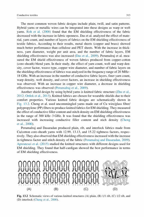
Another shield design by using hybrid yarns is knitted fabric structure (Zhu et al.,
2012; Ortlek et al., 2013). Knitted fabrics are chosen for wearable shields due to their
comfort properties. Various knitted fabric designs are schematically shown in
Fig. 13.2. Cheng et al. used uncommingled yarns made out of Cu wire/glass fiber/
polypropylene (PP) fibers to produce knitted fabrics for EM shielding. They measured
the effect of conductive filler content and stitch density on EM shielding effectiveness
in the range of 300 kHz–3 GHz. It was found that the shielding effectiveness was
increased with increasing conductive filler content and stich density (Cheng
et al., 2000).
Perumalraj and Dasaradan produced plain, rib, and interlock fabrics made from
Cu/cotton core-sheath yarns with 12.99, 13.13, and 15.22 tightness factors, respec-
tively. They also observed that EM shielding effectiveness increased with the increase
in tightness factor and stitch density of the fabric (Perumalraj and Dasaradan, 2009).
Apreutesei et al. (2015) studied the knitted structures with different designs used for
EM shielding. They found that half-cardigan showed the best performance in terms
of EM shielding effectiveness.
(A) (B) (C) (D)
Fig. 13.2 Schematic views of various knitted structures (A) plain, (B) 1/1 rib, (C) 1/2 rib, and
(D) interlock (Cheng et al., 2000).
314 Engineering of High-Performance Textiles
Conductive nonwoven fabrics can be directly made from fibers by melt blowing,
physical, or chemical bonding, etc. For conductive nonwoven fabric production,
conductive fibers can be used directly (Ozen et al., 2013; Ozen and Sancak, 2016).
Conductive coating of nonwovens is another approach to produce EM shielding
nonwoven designs. Conductive coating can be done by several methods such as
sputtering (Sonehara et al., 2008), plasma metallization (Koprowska et al., 2008),
screen printing (Wang et al., 2009), metal coating (Ozen et al., 2016), electroless metal
plating (Han et al., 2001), surface polymerization (Dhawan et al., 2002), and so on.
Ozen et al. prepared needle-punched nonwoven fabrics made from PET/SS,
PP/carbon, and Ag-coated PA fibers and measured the EM shielding performance
in the range of 15–3000 MHz. They investigated the effect of fabric thickness, con-
ductive fiber content, and needle-punch density on EM shielding effectiveness. In par-
allel with the previous research, it was observed that EM shielding effectiveness
values increased with the increase in fabric thickness, conductive filler content,
and needle-punch density (Ozen et al., 2013, 2016; Ozen and Sancak, 2016).
13.4 E-textiles
Electrically conductive fibers and yarns have attracted great interest because of
their distinguished features including reasonable electrical conductivity, flexibil-
ity, electrostatic discharge, and EM interference protection (Tao, 2005; Liu
et al., 2010). Conductive textile fibers and yarns are the primary component for
wearable smart textiles introduced particularly for different applications such as
sensors, EM interference shielding, electrostatic discharge, and data transfer in
clothing; hence, the demand for electrically conductive fibers and yarns is ever-
growing (Kim et al., 2004). The development of novel conductive fibers and yarns
also becomes crucial with technological improvement in wearable electronics such
as wearable displays, solar cells, actuators, data managing devices, and biomedical
sensors (Coyle et al., 2007; Maccioni et al., 2006; Post et al., 2000). Application
requirements play a critical role in selecting the conductivity of smart textile elec-
tronics. For some textile applications like lighting, considerable current is neces-
sary and low ohmic (high conductivity) fibers or yarns are preferred. On the other
hand, for certain sensing or heating applications lower conductivity would work
better; so they require fibers or yarns exhibiting lower electrical conductivity
(Cherenack and van Pieterson, 2012).
Textile electronics need flexible and mechanically stable conducting materials to
ensure electronic capabilities in clothing (R.F. Service, 2003; De Rossi, 2007).
Table 13.3 summarizes the most common fabrication methods to produce conductive
textiles at the fiber and yarn level. Metallic fibers and metallic fiber-based yarns have
been used traditionally as conducting material in wearable electronics. Although
metallic fibers and yarns have various advantages due to their high conductivity, avail-
ability, and relatively low production cost, some drawbacks of these materials, such as
poor flexibility and bendability, heavy weight, and proneness to oxidation under
Table 13.3 Overview of fabrication methods to produce conductivetextile fibers and yarns (Schwarz and Van Langenhove, 2013)
Fiber level Yarn level
During
fabrication
Spinning, wire drawing, melt spinning, wet
spinning
Spinning,
twisting
Posttreatments Coating, ink-jet printing Coating
Conductive textiles 315
ambient conditions, limit their convenience for wearable electronics (Le et al., 2013).
The conventional process to fabricate metal fibers is wire drawing, which is a mechan-
ical fabrication process. Different metal monofilaments including copper (Cu) and
silver-plated copper (Cu/Ag) filaments, brass (Ms) and silver-plated brass (Ms/Ag)
filaments, aluminum (Al) filaments, and copper-clad aluminum (CCA) filaments
are fabricated by the Swiss company Elektrisola Feindraht AG (Escholzmatt, Switzer-
land) (Stoppa and Chiolerio, 2014). These metal filaments are suitable for direct use in
weaving and knitting to produce electronic textiles or they can be blended with all
sorts of textile fibers to fabricate electrically conductive yarns for smart-textile
applications.
In the last two decades, nonmetallic conductive fibers and yarns are introduced for
wearable smart textile applications to ensure better textile properties such as flexibil-
ity, soft handling, drape, and washability. These nonmetallic electroconductive fibers
and yarns are generally fabricated by melt spinning or wet spinning from inherently
conductive polymers and their composites with conductive filler (CNTs, CB, metal
powder, etc.), or by coating textile fibers or yarns with electrically conducting mate-
rials such as conductive polymers, metal powder, CB, and CNTs (Pomfret et al., 1999;
Lu et al., 1996; Xue and Tao, 2005; Xue et al., 2007).
Melt spinning is considered one of the most versatile methods for fabricating
conductive polymeric textile fibers. To this end, high-conductivity blends of
PANI, PPy with polycaprolactone, polyolefins, PS, and poly (ethyleneterephtalate)
polymers are produced by dispersing conductive fillers in a thermoplastic polymer
and blending them by a mechanical mixing process (Hosier et al., 2001; Ikkala et al.,
1995; Yang et al., 1998). The efficiency of the melt-mixing process can be improved
by varying the melting temperature, mechanical mixing time, and mixing speed.
Another method for fabricating conductive fibers is wet spinning. Various wet
spinning techniques have been introduced for the fabrication of conductive fibers
of PANI and its derivatives. For instance, polyblend and block copolymers of
PANI and poly(p-phenylene-terephthalamide) were spun from homogeneous
solutions in concentrated sulfuric acid by Andreatta et al. (Andreatta et al., 1990).
In another study, Mattes et al. (1997) reported PANI fibers spun from highly con-
centrated emeraldine base solution using the wet spinning method. On the other
hand, wet spinning of inherently conductive PANI fibers in a one-step process
was achieved by Pomfret et al. (2000) from the solutions of PANI protonated with
316 Engineering of High-Performance Textiles
2-acrylamido-2-methyl-1-propanesulfonic acid in dichloroacetic acid. Drawbacks
for the wet-spinning production of conductive fibers are the use of large quantities
of coagulation liquids and the necessity to remove solvents after spinning (Bashir
et al., 2011).
Although conductive polymers can be produced in the fiber and yarn form, their
mechanical properties are not suitable for textile processing and applications.
A more economic and efficient method of making textile fibers and yarns electrically
conductive is coating conventional fibers or yarns with a layer of metals, CNTs, or
conducting polymers. By using this strategy, a large variety of conductive fibers or
yarns from natural and synthetic fibers with conductivity ranging from 1�10�6 to
1�104 S cm�1 can be produced (Dubas et al., 2006; Andrews and Weisenberger,
2004; Kang et al., 2010; Yamashita et al., 2013). For instance, Guo et al. (2009) fab-
ricated copper-plated polyester fibers successfully using the electroless deposition
method (Fig. 13.3). Coating conductive polymers on the surface of natural and syn-
thetic textile fibers or yarns is considered a versatile approach for the fabrication of
conductive fibers and yarns for smart textile applications. Most studies are focused on
coating traditional natural and synthetic fibers with PPy and PANI conducting poly-
mers by using in situ solution or vapor-phase polymerization (Bhat et al., 2004;
Dall’Acqua et al., 2004; Kaynak et al., 2008). Fig. 13.4 demonstrates the longitudinal
SEM images of wool, cotton, and nylon 66 yarns coated with PPy using the continuous
vapor polymerization method (Kaynak et al., 2008). Coating of PEDOT on the textile
fibers or yarns for making them electrically conductive was also reported (Knittel and
Schollmeyer, 2009). Another strategy to make the textile fibers conductive is coating
their surface with CNT to utilize its high conductivity feature (Liu et al., 2008). For
instance, Shim et al. (2008a) coated the surface of cotton yarns successfully with a
mixture of CNTs and polyelectrolyte by using the physical padding method to intro-
duce highly conductive yarns. On the other hand, direct sputtering or inking with
metal particles or metal film could be another strategy to make the textile fibers
and yarns conductive. However, this kind of coating generally results in flaking-off
of the metal layer or coating from the fiber surface; so durability of metal coatings
on the fiber surface remains a great challenge (Liu et al., 2010).
10 µm 500 nm
Fig. 13.3 SEM images of copper-plated polyester fibers at different magnifications (Guo
et al., 2009).
20 µm
30 µm
(B)
(A)
(C)
30 µm
Fig. 13.4 SEM images of
PPy-coated wool (A), cotton
(B), and nylon 66 (C) yarns
fabricated by the continuous
vapor-phase method
(Kaynak et al., 2008).
Conductive textiles 317
13.5 Functional coatings
For many applications, it is the material interfaces and surfaces that provide beneficial
functionality over their intrinsic bulk characteristics. Therefore, coatings provide a
versatile method of modifying textiles with conductive properties (Smith, 2010). Sub-
sequently, the textile fabric acts as a supporting structure or carrier material for the
318 Engineering of High-Performance Textiles
conductive finish (Sen, 2007). Conventional techniques such as dip coating or roll
coating are typically used to apply bulk coatings in the form of a saturation or lam-
ination that covers the entire “surface” of the textile. However, as will be presented
herein, the advent of nanotechnology in textile research, the development of novel
process techniques, and the advancement of inks and coating formulations affords
the opportunity to apply coatings to increasingly finer structures. Therefore, the def-
inition of a surface is highly dependent on which scale the coating can influence the
underlying carrier material.
The key to coating these ever finer levels of surface, such as yarns or single fila-
ments of a bulk textile fabric, is inherent in the line-of-sight (Wei, 2009). The coating
formulation is required to be able to overcome various blocking effects and penetrate
the layers of complex three-dimensional (3D) substrates (Hegemann et al., 2009). Fur-
thermore, the subsurface of the polymer that comprises the single filaments can also be
infiltrated and modified with inorganic properties resulting in hybrid finishes that are
neither purely organic nor inorganic ( Jena et al., 2012; Padbury and Jur, 2015). Con-
sequently, a diverse range of unique properties and coating morphologies can be uti-
lized to add extra functionality to textiles while maintaining their inherent properties
such as flexibility, strength, and breathability.
In this section, common methods of applying functional coatings to polymer sub-
strates are introduced including examples of advanced techniques and printing
methods. The field of functional coatings in polymer and textile manufacturing is
extremely broad. Therefore, the objective of Section 13.5 is to provide a qualitative
overview of various techniques from the perspectives of the authors. More detailed
and theoretical descriptions regarding coating techniques can be found elsewhere
in the literature and are referenced in Section 13.5 where applicable.
13.5.1 Percolation threshold
A typical coating formulation incorporates a binder or matrix material that adheres to
the fabric and provides durability with the addition of functional fillers for conductiv-
ity. Epoxies, polyacrylates, polyurethanes, and polyvinyl chlorides have been fre-
quently used as binder materials due to their additional properties such as
durability and mechanical strength (Tracton, 2005). However, the range of matrix
materials is greatly expanded by the abundance of raw materials such as polymer-
solvent combinations and thermoplastic polymers (Smith, 2010; Sen, 2007;
Tracton, 2005). Fillers of various materials such as nickel, silver, copper, and CB
in the form of powders, flakes, or filaments are incorporated into the matrix with
the objective of creating a conductive network (Nishikawa et al., 2010). In recent
years, more novel materials have been used such as graphene and CNTs resulting
in unprecedented conductivities (Bauhofer and Kovacs, 2009; Li et al., 2008; Shim
et al., 2008b).
Conductive networks in coatings are created by reaching a percolation threshold.
Mathematically, percolation theory describes the formation of long-range connectivity
in anotherwise randomarrangement (Sahimi, 1994).At lowconcentrations, conductive
fillers in a dielectric matrix are situated in random discrete locations. However, as the
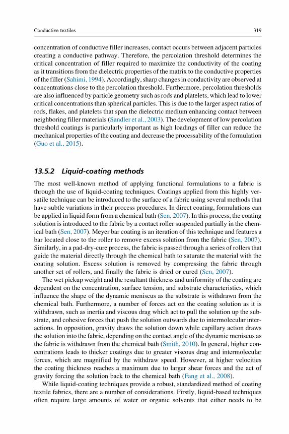
Conductive textiles 319
concentration of conductive filler increases, contact occurs between adjacent particles
creating a conductive pathway. Therefore, the percolation threshold determines the
critical concentration of filler required to maximize the conductivity of the coating
as it transitions from the dielectric properties of the matrix to the conductive properties
of the filler (Sahimi, 1994). Accordingly, sharp changes in conductivity are observed at
concentrations close to the percolation threshold. Furthermore, percolation thresholds
are also influenced by particle geometry such as rods and platelets, which lead to lower
critical concentrations than spherical particles. This is due to the larger aspect ratios of
rods, flakes, and platelets that span the dielectric medium enhancing contact between
neighboring filler materials (Sandler et al., 2003). The development of low percolation
threshold coatings is particularly important as high loadings of filler can reduce the
mechanical properties of the coating and decrease the processability of the formulation
(Guo et al., 2015).
13.5.2 Liquid-coating methods
The most well-known method of applying functional formulations to a fabric is
through the use of liquid-coating techniques. Coatings applied from this highly ver-
satile technique can be introduced to the surface of a fabric using several methods that
have subtle variations in their process procedures. In direct coating, formulations can
be applied in liquid form from a chemical bath (Sen, 2007). In this process, the coating
solution is introduced to the fabric by a contact roller suspended partially in the chem-
ical bath (Sen, 2007). Meyer bar coating is an iteration of this technique and features a
bar located close to the roller to remove excess solution from the fabric (Sen, 2007).
Similarly, in a pad-dry-cure process, the fabric is passed through a series of rollers that
guide the material directly through the chemical bath to saturate the material with the
coating solution. Excess solution is removed by compressing the fabric through
another set of rollers, and finally the fabric is dried or cured (Sen, 2007).
The wet pickup weight and the resultant thickness and uniformity of the coating are
dependent on the concentration, surface tension, and substrate characteristics, which
influence the shape of the dynamic meniscus as the substrate is withdrawn from the
chemical bath. Furthermore, a number of forces act on the coating solution as it is
withdrawn, such as inertia and viscous drag which act to pull the solution up the sub-
strate, and cohesive forces that push the solution outwards due to intermolecular inter-
actions. In opposition, gravity draws the solution down while capillary action draws
the solution into the fabric, depending on the contact angle of the dynamic meniscus as
the fabric is withdrawn from the chemical bath (Smith, 2010). In general, higher con-
centrations leads to thicker coatings due to greater viscous drag and intermolecular
forces, which are magnified by the withdraw speed. However, at higher velocities
the coating thickness reaches a maximum due to larger shear forces and the act of
gravity forcing the solution back to the chemical bath (Fang et al., 2008).
While liquid-coating techniques provide a robust, standardized method of coating
textile fabrics, there are a number of considerations. Firstly, liquid-based techniques
often require large amounts of water or organic solvents that either needs to be
320 Engineering of High-Performance Textiles
disposed of or recovered, which increases the chemical footprint of the technique.
Moreover, liquid-coating processes are energy intensive due to the several steps
required to apply solutions followed by the use of large drying ovens to cure the coat-
ing or evaporate the residual solvent. However, alternative polymer chemistries that
require less energy intensive curing steps or utilize fewer chemicals are available. For
example, UV curable resins are widely available and UV lamps can replace energy
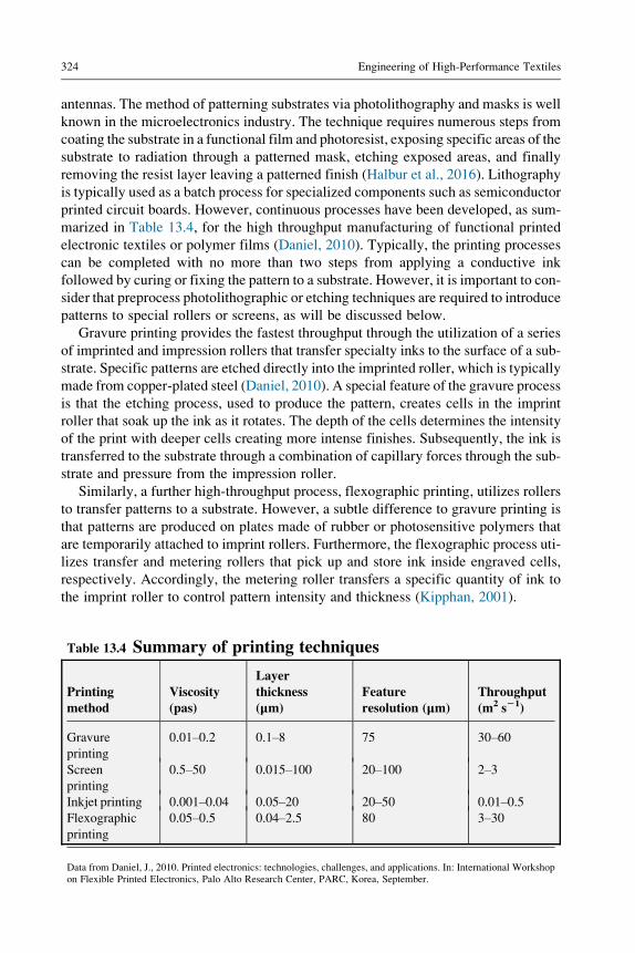
Data from Daniel, J., 2010. Printed electronics: technologies, challenges, and applications. In: International Workshopon Flexible Printed Electronics, Palo Alto Research Center, PARC, Korea, September.
Conductive textiles 325
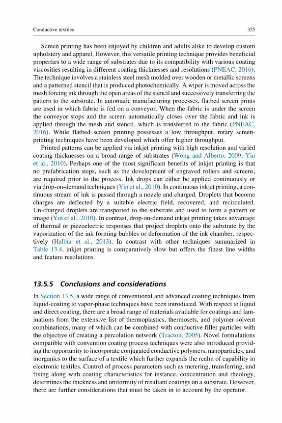
Screen printing has been enjoyed by children and adults alike to develop custom
upholstery and apparel. However, this versatile printing technique provides beneficial
properties to a wide range of substrates due to its compatibility with various coating
viscosities resulting in different coating thicknesses and resolutions (PNEAC, 2016).
The technique involves a stainless steel mesh molded over wooden or metallic screens
and a patterned stencil that is produced photochemically. A wiper is moved across the
mesh forcing ink through the open areas of the stencil and successively transferring the
pattern to the substrate. In automatic manufacturing processes, flatbed screen prints
are used in which fabric is fed on a conveyor. When the fabric is under the screen
the conveyor stops and the screen automatically closes over the fabric and ink is
applied through the mesh and stencil, which is transferred to the fabric (PNEAC,
2016). While flatbed screen printing possesses a low throughput, rotary screen-
printing techniques have been developed which offer higher throughput.
Printed patterns can be applied via inkjet printing with high resolution and varied
coating thicknesses on a broad range of substrates (Wong and Alberto, 2009; Yin
et al., 2010). Perhaps one of the most significant benefits of inkjet printing is that
no prefabrication steps, such as the development of engraved rollers and screens,
are required prior to the process. Ink drops can either be applied continuously or
via drop-on-demand techniques (Yin et al., 2010). In continuous inkjet printing, a con-
tinuous stream of ink is passed through a nozzle and charged. Droplets that become
charges are deflected by a suitable electric field, recovered, and recirculated.
Un-charged droplets are transported to the substrate and used to form a pattern or
image (Yin et al., 2010). In contrast, drop-on-demand inkjet printing takes advantage
of thermal or piezoelectric responses that project droplets onto the substrate by the
vaporization of the ink forming bubbles or deformation of the ink chamber, respec-
tively (Halbur et al., 2013). In contrast with other techniques summarized in
Table 13.4, inkjet printing is comparatively slow but offers the finest line widths
and feature resolutions.
13.5.5 Conclusions and considerations
In Section 13.5, a wide range of conventional and advanced coating techniques from
liquid-coating to vapor-phase techniques have been introduced. With respect to liquid
and direct coating, there are a broad range of materials available for coatings and lam-
inations from the extensive list of thermoplastics, thermosets, and polymer-solvent
combinations, many of which can be combined with conductive filler particles with
the objective of creating a percolation network (Tracton, 2005). Novel formulations
compatible with convention coating process techniques were also introduced provid-
ing the opportunity to incorporate conjugated conductive polymers, nanoparticles, and
inorganics to the surface of a textile which further expands the realm of capability in
electronic textiles. Control of process parameters such as metering, transferring, and
fixing along with coating characteristics for instance, concentration and rheology,
determines the thickness and uniformity of resultant coatings on a substrate. However,
there are further considerations that must be taken in to account by the operator.
326 Engineering of High-Performance Textiles
Explicitly, the chemical compatibility between the coating material and the
substrate determines the wettability and adhesion of the resultant coating, as intro-
duced in Section 13.5.2. Wettability and adhesion is highly dependent on the sur-
face tension of the two materials as well as the interfacial tension between the two
components (Smith, 2010). In general, a low-surface-tension substrate can result
in nonwetting behavior if the surface tension of the liquid is greater than the sur-
face tension of the substrate. In this case, the adhesive force of the substrate is
unable to overcome the cohesive forces of the coating solution. As a result, the
coating formulation acts to minimize its own surface energy by beading up rather
than uniformly spreading over the substrate. In the case of polymer coatings,
adhesion is also impacted by the diffusion of polymer chains into the substrate.
Polymer chains have greater mobility above the glass transition temperature;
therefore, in the case of hot-melt coating, higher temperature can lead to stronger
adhesion forces (Smith, 2010; Wei, 2009). However, diffusion and entanglement
of polymer chains is also dependent on chemical compatibility between the poly-
mers that make up the coating formulation and substrate. Low solubility param-
eters and repulsive forces between dissimilar polymers result in phase separation,
in the same way that oil separates from water, which can result in coating delam-
ination and reduced durability. To increase the adhesive force, high molecular
weight results in greater attractive interactions between neighboring polymer
chains, such as hydrogen bonds and van der Waals forces. Practically, textile fab-
rics are not perfectly smooth substrates; they inherently possess some surface
roughness that may influence wettability, adhesion, and the uniformity of a coat-
ing. Furthermore, textile fabrics are porous which can lead to capillary action or
wicking. For printing, capillary action can affect the resolution of line widths as
the solution is drawn into the fabric. On the other hand, for bulk coatings, pen-
etration into the fabric structure can enhance the mechanical properties of the sub-
strate up to a certain limit through mechanical locking (Smith, 2010).
While chemical compatibility and wettability may affect the uniformity and dura-
bility of coatings on a substrate, there are further considerations for printed patterns
made from polymer-solvent formulations. Firstly, incompatibility may result in non-
uniform line widths due to higher contact angles between the coating formulation and
substrate surface which impacts the minimum resolution possible. Furthermore, sol-
vents tend to evaporate quicker at the edges due to the microscopic crescent shape of
the liquid-gas interface of the coating. As the solvent evaporates, liquid moves out-
wards to replace the liquid that has evaporated. For inks and formulations that contain
a conductive particle component, coffee ring patterns can form where the flow of liq-
uid from the canter of the drop drags particles to the outside (Yin et al., 2010; Halbur
et al., 2013). The nonuniformity of the line widths and coffee ring pattern may result in
lower conductivities and potential short circuits.
Ultimately, the utilization of the coating and printing techniques outlined in this
section is a balance between cost (i.e., capital investment and throughput), coating
properties such as resolution (feature size) and thickness as well as the compatibility
between substrates and coating formulations.
Conductive textiles 327
References
A. D4935-99, 1999. Standard Test Method for Measuring the Electromagnetic Shielding
Effectiveness of Planar Materials.
A. E1851-15, 2015. Standard TestMethod for Electromagnetic Shielding Effectiveness of Dura-
ble Rigid Wall Relocatable Structures. ASTM International, West Conshohocken, PA.
Agnihotri, N., Chakrabarti, K., De, A., 2015. Highly efficient electromagnetic inter-
ference shielding using graphite nanoplatelet/poly(3,4-ethylenedioxythiophene)-poly
(styrenesulfonate) composites with enhanced thermal conductivity. RSC Adv. 5 (54),
43765–43771.Akyildiz, H.I., Padbury, R.P., Parsons, G.N., Jur, J.S., 2012. Temperature and exposure depen-
dence of hybrid organic-inorganic layer formation by sequential vapor infiltration into
CNT/polymer composites. Carbon 47 (7), 1738–1746.Andreatta, A., Heeger, A.J., Smith, P., 1990. Electrically conductive poly blend fibers of poly-
aniline and poly(p-phenylene terephthalamide). Polym. Commun. 31, 275.
Andrews, R., Weisenberger, M., 2004. Carbon nanotube polymer composites. Curr. Opinion
Solid State Mater. Sci. 8, 31–37.Apreutesei, A.L., Curteza, A., David, V., Nica, I., Rau, M., Baltag, O., 2014. Investigation of the
textile structures with different design used in electromagnetic shielding. In: 2014 Inter-
national Conference and Exposition on Electrical and Power Engineering (EPE),
pp. 596–601.Apreutesei, A.L., Curteza, A., Baltag, O., 2015. Study of the knitted structures with different
designs used for electromagnetic shielding. In: 2015 9th International Symposium on
Advanced Topics in Electrical Engineering (ATEE), pp. 352–355.Avloni, J., Ouyang, M., Florio, L., Henn, A.R., Sparavigna, A., 2007. Shielding effectiveness
evaluation of metallized and polypyrrole-coated fabrics. J. Thermoplast. Compos. Mater.
20 (3), 241–254.Badic, W., Marinescu, M.J., 2002. The failure of coaxial TEM cells ASTM standards methods
in HF range. In: 2002 IEEE International Symposium on Electromagnetic Compatibility,
Vols 1 and 2, Symposium Record, pp. 29–34.Bajgar, V., Penhaker, M., Martinkova, L., Pavlovic, A., Bober, P., Trchova, M., Stejskal, J.,
2016. Cotton fabric coated with conducting polymers and its application in monitoring
of carnivorous plant response. Sensors 16 (4), 495.
Bashir, T., Skrifvars, M., Persson, N.K., 2011. Production of highly conductive textile viscose
yarns by chemical vapor deposition technique: a route to continuous process. Polym. Adv.
Technol. 22, 2214–2221.Bauhofer, W., Kovacs, J.Z., 2009. A review and analysis of electrical percolation in carbon
nanotube polymer composites. Compos. Sci. Technol. 69 (10), 1486–1498.Bhat, N., Seshadri, D., Radhakrishnan, S., 2004. Preparation, characterization, and performance
of conductive fabrics: cotton + PANi. Text. Res. J. 74, 155–166.Cetiner, S., 2014. Dielectric and morphological studies of nanostructured polypyrrole-coated
1999. Plasma-assisted chemical vapor deposition of dielectric thin films for ULSI semi-
conductor circuits. J. Res. Dev. Educ. 43, 5.
Coyle, S., Wu, Y., Lau, K.-T., De Rossi, D., Wallace, G., Diamond, D., 2007. Smart nan-
otextiles: a review of materials and applications. MRS Bull. 32, 434–442.Cushing, B.L., Kolesnichenko, V.L., O’Connor, C.J., 2004. Recent advances in the liquid-phase
syntheses of inorganic nanoparticles. Chem. Rev. 104, 3893.
taining cotton/metal-wrapped hybrid yarns. J. Ind. Text 46 (4), 1084–1103.Fang, H.-W., et al., 2008. Dip coating assisted polylactic acid deposition on steel surface: film
thickness affected by drag force and gravity. Mater. Lett. 62 (21–22), 3739–3741.Feldheim, D.L., Grabar, K.C., Natan, M.J., Mallouk, T.E., 1996. Electron transfer in self assem-
bled inorganic polyelectrolyte/metal nanoparticle heterostructures. J. Am. Chem. Soc.
118, 7640–7641.Ferreira, M., Cheung, J.H., Rubner, M.F., 2016. Molecular self-assembly of conjugated poly-
ions: a new process for fabricating multilayer thin film heterostructures. Thin Solid Films
methods and materials-a review. J. Appl. Polym. Sci. 112 (4), 2073–2086.Ghosh, P., Chakrabarti, A., 2000. Conducting carbon black filled EPDM vulcanizates: assess-
ment of dependence of physical and mechanical properties and conducting character on
variation of filler loading. Eur. Polym. J. 36 (5), 1043–1054.Guo, R., Jiang, S., Yuen, C.M., Ng, M., 2009. Surface characterisation of electroless copper
plated polyester fibres. Surf. Eng. 25, 101–105.Guo, C., et al., 2015. Preparation of the polypropylene/nickel coated glass fibers conductive
composites with a Low percolation threshold. Mater. Lett. 143, 124–127.Halbur, J.C., Padbury, R.P., Jur, J.S., 2013. Inducedwetting of polytetrafluoroethylene by atomic
thin films by UV aided metalized laser printing. J. Vac. Sci. Technol. A 34 (3), 031402.
Hammond, P.T., 2004. Form and function in multilayer assembly: new applications at the nano-
scale. Adv. Mater. 16, 1271.
Hampdensmith, M.J., Kodas, T.T., 1995. Chemical-vapor-deposition of metals. 1. An overview
of CVD processes. Chem. Vap. Depos. 1, 8.
Han, E.G., Kim, E.A., Oh, K.W., 2001. Electromagnetic interference shielding effectiveness of
electroless Cu-plated PET fabrics. Synth. Met. 123 (3), 469–476.Hegemann, D., Amberg, M., Ritter, A., Heuberger, M., 2009. Recent developments in Ag meta-
llised textiles using plasma sputtering. Mater. Technol. 24 (1), 41–45.Hench, L.L., West, J.K., 1990. The sol-gel process. Chem. Rev. 90 (1), 33–72.Hosier, I., Vaughan, A., Patel, D., Sutton, S., Swingler, S., 2001. Morphology and electrical
conductivity in polyaniline/polyolefin blends. IEEE Trans. Dielectr. Electr. Insul.
8, 698–704.Huang, J.C., 1995. Emi shielding plastics—a review. Adv. Polym. Technol. 14 (2), 137–150.I.S. 299-1997, 1997. IEEE Standard Method for Measuring the Effectiveness of Electromag-
netic Shielding Enclosures. The Institute of Electrical and Electronics Engineers,
New York.
Ikkala, O., Laakso, J., V€akiparta, K., Virtanen, E., Ruohonen, H., J€arvinen, H., Taka, T.,
polyaniline: conducting melt processible polymer blends. Synth. Met. 69, 97–100.Jagatheesan, K., Ramasamy, A., Das, A., Basu, A., 2015. Fabrics and their composites for elec-
tromagnetic shielding applications. Text. Prog. 47 (2), 87–161.Jena, K.K., Rout, T.K., Narayan, R., Raju, K., 2012. Novel organicinorganic hybrid coatings
prepared by the sol-gel process: corrosion and mechanical properties. Polym. Int.
61, 1101–1106.Jur, J.S., Spagnola, J.C., Lee, K., Gong, B., Peng, Q., Parsons, G.N., 2010. Temperature depen-
dent subsurface growth during atomic layer deposition on polypropylene and cellulose
fibers. Langmuir 26 (11), 8239–8244.Jur, J.S., Sweet III, W.J., Oldham, C.J., Parsons, G.N., 2011. Atomic layer deposition of conduc-
tive coatings on cotton, paper, and synthetic fibers: conductivity analysis and functional
chemical sensing using “all-fiber” capacitors. Adv. Funct. Mater. 21 (11), 1993–2002.Kang, T.J., Choi, A., Kim, D.-H., Jin, K., Seo, D.K., Jeong, D.H., Hong, S.-H., Park, Y.W.,
Kim, Y.H., 2010. Electromechanical properties of CNT-coated cotton yarn for electronic
Kim, M.S., Kim, H.K., Byun, S.W., Jeong, S.H., Hong, Y.K., Joo, J.S., Song, K.T., Kim, J.K.,
Lee, C.J., Lee, J.Y., 2002. PET fabric/polypyrrole composite with high electrical conduc-
tivity for EMI shielding. Synth. Met. 126 (2–3), 233–239.Kim, H.K., Kim, M.S., Song, K., Park, Y.H., Kim, S.H., Joo, J., Lee, J.Y., 2003. EMI shielding
properties of PP and PET conductive polymer fibers. Synth. Met. 146, 167–174.Kim, Y., Davis, R., Cain, A., Grunlan, J., 2011. Development of layer-by-layer assembled car-
Lu, G., Li, X., Jiang, H., 1996. Electrical and shielding properties of ABS resin filled with
nickel-coated carbon fibers. Compos. Sci. Technol. 56, 193–200.Luka, G., et al., 2010. Transparent and conductive undoped zinc oxide thin films grown by
atomic layer deposition. Phys. Status Solidi 207, 1568–1571.Luo, X.C., Chung, D.D.L., 1999. Electromagnetic interference shielding using continuous carbon-
fiber carbon-matrix and polymer-matrix composites. Compos. Part B 30 (3), 227–231.Macasaquit, A.C., Binag, C.A., 2010. Preparation of conducting polyester textile by in situ poly-
merization of pyrrole. Philipp. J. Sci. 139 (2), 189–196.Maccioni, M., Orgiu, E., Cosseddu, P., Locci, S., Bonfiglio, A., 2006. Towards the textile tran-
sistor: assembly and characterization of an organic field effect transistor with a cylindrical
mance of hybrid yarn knitted fabrics with anechoic chamber method. Text. Res. J. 83 (1),
90–99.Ozen, M.S., Sancak, E., 2016. Investigation of electromagnetic shielding effectiveness of nee-
dle punched nonwoven fabrics with staple polypropylene and carbon fibres. J. Text. Inst.
107 (2), 249–257.Ozen, M.S., Sancak, E., Beyit, A., Usta, I., Akalin, M., 2013. Investigation of electromagnetic
shielding properties of needle-punched nonwoven fabrics with stainless steel and polyester
fiber. Text. Res. J. 83 (8), 849–858.Ozen, M.S., Sancak, E., Soin, N., Shah, T.H., Siores, E., 2016. Investigation of electromagnetic
shielding effectiveness of needle punched nonwoven fabric produced from conductive sil-
ver coated staple polyamide fibre. J. Text. Inst. 107 (7), 912–922.Padbury, R.P., Jur, J.S., 2014. Temperature-dependent infiltration of polymers during sequen-
tial exposures to trimethylaluminum. Langmuir 30 (30), 9228–9238.Padbury, R., Jur, J., 2015. Systematic study of trimethyl aluminum infiltration in polyethylene
terephthalate and its effect on the mechanical properties of polyethylene terephthalate
interference shielding through the use of functionalized carbon-nanotube-reactive polymer
composites. IEEE Trans. Nanotechnol. 9 (4), 464–469.Parsons, G.N., George, S.M., Knez, M., 2011. Progress and future directions for atomic layer
deposition and ALD-based chemistry. MRS Bull. 36 (11), 865–871.Perumalraj, R., Dasaradan, B.S., 2009. Electromagnetic shielding effectiveness of copper core
yarn knitted fabrics. Indian J. Fibre Text. Res. 34 (2), 149–154.Perumalraj, R., Dasaradan, B.S., Anbarasu, R., Arokiaraj, P., Harish, S.L., 2009. Electromag-
netic shielding effectiveness of copper core-woven fabrics. J. Text. Inst. 100 (6), 512–524.Perumalraj, R., Nalankilli, G., Balasaravanan, T.R., Roshanraja, K., Shyamsundar, G.,
Dasaradan, B.S., 2010. Electromagnetic shielding tester for conductive textile materials.
Indian J. Fibre Text. Res. 35 (4), 361–365.PNEAC, 2016. Printing Process Descriptions: Environment and Printing: The Printers’ National
Environmental Assistance Center: PNEAC: The Environmental Informationwebsite for
the Printing Industry. Pneac.org. N.p. (accesed 21 August 2016).
Pomfret, S., Adams, P., Comfort, N., Monkman, A., 1999. Advances in processing routes for
conductive polyaniline fibres. Synth. Met. 101, 724–725.Pomfret, S., Adams, P., Comfort, N., Monkman, A., 2000. Electrical and mechanical properties
of polyaniline fibres produced by a one-step wet spinning process. Polymer
41, 2265–2269.Post, E.R., Orth, M., Russo, P., Gershenfeld, N., 2000. E-broidery: design and fabrication of
textile-based computing. IBM Syst. J. 39, 840–860.Puurunen, R.L., 2005. Surface chemistry of atomic layer deposition: a case study for the
trimethylaluminum/water process. J. Appl. Phys. 97 (12), 121301.
R.F. Service, 2003. Electronic textiles charge ahead. Science 301, 909–911.Rau, M., Iftemie, A., Baltag, O., Costandache, D., 2011. The study of the electromagnetic
shielding properties of a textile material with amorphous microwire. Adv. Electr. Comput.
Eng. 11 (1), 17–22.Rea, S., Linton, D., Orr, E., McConnell, J., 2005. Electromagnetic shielding properties of carbon
multifunctional metal composite fabrics. Text. Res. J. 78 (9), 825–835.Rubacha, M., Zieba, J., 2006. Magnetic textile elements. Fibres Text. East. Eur. 14 (5), 49–53.Rubacha, M., Zieba, J., 2007. Magnetic cellulose fibres and their application in textronics.
Fibres Text. East. Eur. 15 (5–6), 101–104.Sahimi, M., 1994. Applications of Percolation Theory. Taylor & Francis, London.
electromagnetic interference shielding at elevated temperatures. Adv. Mater. 26 (21),
3484–3489.Wong, W.S., Alberto, S. (Eds.), 2009. Flexible electronics: materials and applications-
Vol. 11. Springer Science & Business Media, New York.
Wu, B., et al., 2015. Electrical switchability and dry-wash durability of conductive textiles. Sci.
Rep. 5, 11255.
Xiong, G.X., Zhang, Z.B., Deng, M., Zhou, Y.F., 2011. Investigation of electromagnetic inter-
ference shielding effectiveness of cement-based composites filled with carbon materials.
Adv. Mater. Res. 168–170, 1021–1024.Xue, P., Tao, X., 2005. Morphological and electromechanical studies of fibers coated with elec-
trically conductive polymer. J. Appl. Polym. Sci. 98, 1844–1854.Xue, P., Park, K., Tao, X., Chen, W., Cheng, X., 2007. Electrically conductive yarns based on