39
MODULE 2.3 UNIT 2.3.1 1 st & 2 nd Fixing Conduit & Trunking Systems PHASE:2 Electrical Learning Notes
MODULE 2.3 UNIT 2.3.1
1st & 2nd Fixing
Conduit
&
Trunking Systems PHASE:2
2]
Electrical Learning Notes
Table of Contents
STEEL TRUNKING ...................................................................................................................................... 3
TYPES AND SIZES OF STEEL TRUNKING ............................................................................................................ 3 AREAS OF APPLICATION.................................................................................................................................. 10 TYPES OF SUPPORT ......................................................................................................................................... 10 SPACING OF SUPPORTS ................................................................................................................................... 11 CABLE CAPACITY AND SPACE FACTOR ........................................................................................................... 11 FABRICATION AND INSTALLATION OF TEES AND BENDS ................................................................................. 11 FORMING A TEE JOINT .................................................................................................................................... 12 FORMING AN INTERNAL BEND ........................................................................................................................ 13 FORMING AN EXTERNAL BEND ....................................................................................................................... 14 FORMING A FLAT BEND .................................................................................................................................. 15 EARTHING OF STEEL TRUNKING ..................................................................................................................... 16
OVERVIEW OF CONDUIT TYPES ......................................................................................................... 17
STEEL CONDUIT SYSTEM ..................................................................................................................... 17
TYPES AND SIZES OF STEEL CONDUIT ............................................................................................................. 17 EDDY CURRENTS IN STEEL CONDUIT .............................................................................................................. 17 SOME ADVANTAGES OF STEEL CONDUIT ........................................................................................................ 17 SOME DISADVANTAGES OF STEEL CONDUIT ................................................................................................... 18 CABLE CAPACITY OF STEEL CONDUIT ( SPACE FACTOR ) ............................................................................... 18 CUTTING STEEL CONDUIT ............................................................................................................................... 18 THREADING STEEL CONDUIT .......................................................................................................................... 19 FITTING AND FIXING STEEL CONDUIT ............................................................................................................. 19 SPACING OF SUPPORTS FOR CONDUITS ........................................................................................................... 19 SADDLES ........................................................................................................................................................ 20 DISTANCE SADDLES........................................................................................................................................ 21 MULTIPLE SADDLES........................................................................................................................................ 21 TERMINATION OF STEEL CONDUIT TO ENCLOSURES ....................................................................................... 22 COUPLING AND MALE BUSH METHOD ............................................................................................................ 22 LOCKNUT AND FEMALE BRASS BUSH METHOD .............................................................................................. 22 GALVANISED STEEL CONDUIT ACCESSORIES .................................................................................................. 23 JOINTING STEEL CONDUIT .............................................................................................................................. 24
BENDING STEEL CONDUIT ................................................................................................................... 26
SETTING UP SEQUENCE OF A BENDING MACHINE ........................................................................................... 25 MAKING A 90O BEND IN STEEL CONDUIT ........................................................................................................ 26 MAKING A DOUBLE SET OR OFFSET IN STEEL CONDUIT ................................................................................. 28 FORMING OF A 30° OFFSET ............................................................................................................................. 28 FORMING A 45° OFFSET .................................................................................................................................. 30 MAKING A SADDLE SET (JUMP) IN STEEL CONDUIT ........................................................................................ 31 MAKING A DOUBLE 90O BEND IN STEEL CONDUIT ......................................................................................... 34
PVC CONDUIT ........................................................................................................................................... 35
COMPOSITION OF PVC CONDUIT .................................................................................................................... 35 CHOICE OF PVC CONDUIT .............................................................................................................................. 35 JOINTING PVC CONDUIT ................................................................................................................................. 35 PRECAUTIONS WHEN USING ADHESIVES ........................................................................................................ 35 EXPANSION OF PVC CONDUIT ........................................................................................................................ 35 FITTING AND FIXING OF PVC CONDUIT .......................................................................................................... 36 ADVANTAGES OF PVC CONDUIT .................................................................................................................... 36 DISADVANTAGES OF PVC CONDUIT ............................................................................................................... 36 WORKING WITH PVC CONDUIT ...................................................................................................................... 37 HOT BENDING OF PVC CONDUIT .................................................................................................................... 38
UNIT RELATED ETCI RULES ................................................................................................................ 39

SOLAS Electrical Course Notes - Unit 2.3.1
Revision 4, November 2013 3
Steel Trunking
A trunking is an enclosure that provides for the protection of cables. It is normally square or
rectangular in cross section, and has a removable lid.
A trunking system offers great flexibility when used in conjunction with conduit systems.
Trunking forms the backbone or framework of an installation. Conduits run from the trunking
to accessory outlet boxes.
When an alteration or extension is required to an installation it is easy to drill a hole in the side
of the trunking and run a conduit to the new accessory point. New wiring can then be drawn
through the new conduit and the existing trunking to the supply point.
Types and Sizes of Steel Trunking
There are a number of types of steel trunking such as:-
Lighting Trunking
Cable trunking
Multi-Compartment trunking
Bus-bar Trunking
Typical surface finishes.
Hot dipped galvanised coating
Grey enamel on zinc coating
Silver enamel on zinc coating
Stainless steel
Standard Sizes of Trunking
50mm x 50mm 150mm x 75mm
75mm x 50mm 150mm x 100mm
75mm x 75mm 150mm x 150mm
100mm x 50mm 200mm x 100mm
100mm x 75mm 225mm x 150mm
100mm x 50mm 250mm x 150mm
100mm x 100mm 300mm x 250mm
Trunking is generally supplied in 3 metre lengths. Lighting trunking is often supplied in 5 metre
lengths. Other lengths are available on request.

SOLAS Electrical Course Notes - Unit 2.3.1
Revision 4, November 2013 4
Lighting Trunking
Steel trunking may be used to install luminaires. This type has quick fit drive-in couplings,
which allow for fast, easy installation of long runs. The trunking is installed with the opening
downwards as shown in Figure 1.
.
Trunking Drive-in coupling
Figure 1
A range of fittings is available to accommodate changes in direction, tees and intersections.
These are bolted in position using at least two bolts depending on trunking size.
See Figure 2

SOLAS Electrical Course Notes - Unit 2.3.1
Revision 4, November 2013 5
Flat Bend Tee
Figure 2
SOLAS Electrical Course Notes - Unit 2.3.1
Revision 4, November 2013 6
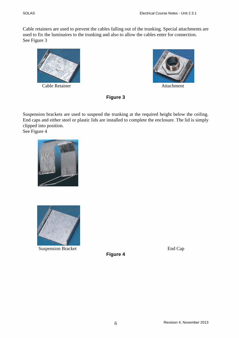
Cable retainers are used to prevent the cables falling out of the trunking. Special attachments are
used to fix the luminaires to the trunking and also to allow the cables enter for connection.
See Figure 3
Cable Retainer Attachment
Figure 3
Suspension brackets are used to suspend the trunking at the required height below the ceiling.
End caps and either steel or plastic lids are installed to complete the enclosure. The lid is simply
clipped into position.
See Figure 4
Suspension Bracket End Cap
Figure 4
SOLAS Electrical Course Notes - Unit 2.3.1
Revision 4, November 2013 7
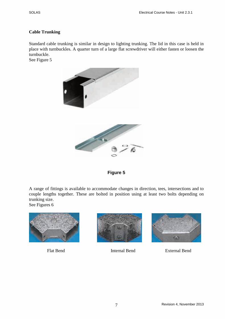
Cable Trunking
Standard cable trunking is similar in design to lighting trunking. The lid in this case is held in
place with turnbuckles. A quarter turn of a large flat screwdriver will either fasten or loosen the
turnbuckle.
See Figure 5
Figure 5
A range of fittings is available to accommodate changes in direction, tees, intersections and to
couple lengths together. These are bolted in position using at least two bolts depending on
trunking size.
See Figures 6
Flat Bend Internal Bend External Bend

SOLAS Electrical Course Notes - Unit 2.3.1
Revision 4, November 2013 8
Tee 45° Bend Coupling
Figure 6

SOLAS Electrical Course Notes - Unit 2.3.1
Revision 4, November 2013 9
Changes in trunking size are simply made by using reducers. Cables are easily kept in place in
the trunking with cable retainers. End caps are used to complete the enclosure.
See Figure 7
Reducer Cable Retainer End Cap
Figure 7
Multi-Compartment trunking
The increasing use of electronics and differing voltage levels in industrial installations has
necessitated the use of multi-compartment trunking, which is designed to segregate ( separate )
the various voltages and services.
Segregation of this nature is a requirement of the ETCI Rules. For example, it prevents an extra
low voltage system, coming into contact with a low voltage system even in the event of a fault.
Figure 8 shows a typical section of multi-compartment trunking.
Figure 8
230-400 V Cables
Computer Cables
Up to 50 V Cables
SOLAS Electrical Course Notes - Unit 2.3.1
Revision 4, November 2013 10
Areas of Application
Steel trunking systems are used in commercial and industrial premises. Lighting trunking is
generally used to supply and support fluorescent fittings, which illuminate large floor areas.
Cable trunking is installed at a suitable height around the walls of the building. Conduit drops
are then used to supply outlet points. Multi-compartment trunking is used where different
electrical services are required in close proximity to each other. It is ideal in large offices and
classrooms. Here it may be used to accommodate cables for supplying equipment at 230 Volts,
plus data cables for computers, printers etc. These supplies must be segregated from each other.
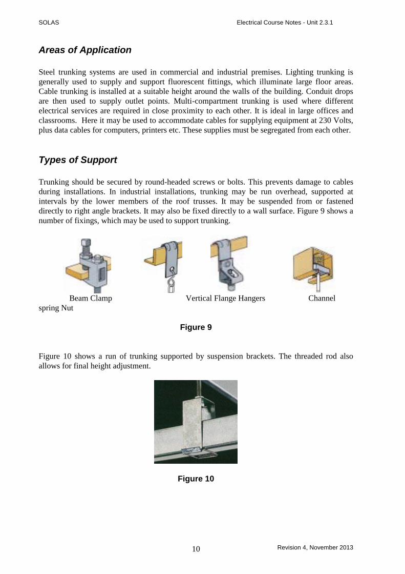
Types of Support
Trunking should be secured by round-headed screws or bolts. This prevents damage to cables
during installations. In industrial installations, trunking may be run overhead, supported at
intervals by the lower members of the roof trusses. It may be suspended from or fastened
directly to right angle brackets. It may also be fixed directly to a wall surface. Figure 9 shows a
number of fixings, which may be used to support trunking.
Beam Clamp Vertical Flange Hangers Channel
spring Nut
Figure 9
Figure 10 shows a run of trunking supported by suspension brackets. The threaded rod also
allows for final height adjustment.
Figure 10

SOLAS Electrical Course Notes - Unit 2.3.1
Revision 4, November 2013 11
Spacing of Supports
The spacing of trunking supports is not a simple topic as there are so many variables such as: -
size of trunking, size and number of cables to be installed, type and strength of support
available. However the following table lists the maximum distances between supports for steel
trunking.
Maximum Support Spacing for Steel Trunking
Trunking Size Horizontal Vertical
50 x 50 1.75 2.0
75 x 50 3.0 3.0
Larger Sizes 3.0 3.0
Cable Capacity and Space Factor
Trunking is primarily intended for the installation of PVC insulated cables. The maximum
number of cables that can be installed in a trunking system is based on only 45% of the
available space being occupied. This does not mean that the trunking should appear to be less
than half full of cable. Remember that all the unoccupied space in between the cables is
included in the calculation.
The main reason for limiting the number of cables to this level is to eliminate problems
associated with an excessive build up of heat inside the trunking. If too many cables are
installed the cable insulation will suffer damage due to overheating. There is also the possibility
of fire risk.
The ETCI Rules provides a handy guide to aid the calculation of the cable capacity of trunking.
It allows for a mixture of all the common cable sizes up to 10 mm2. Other cable sizes have to be
accounted for on an individual basis. Remember that the overall cable CSA must be used in the
calculation ( not the CSA of the conductor alone ).
If multi-core cables are to be installed in trunking the 45% space factor still applies, except in
the case of one multi-core cable only.
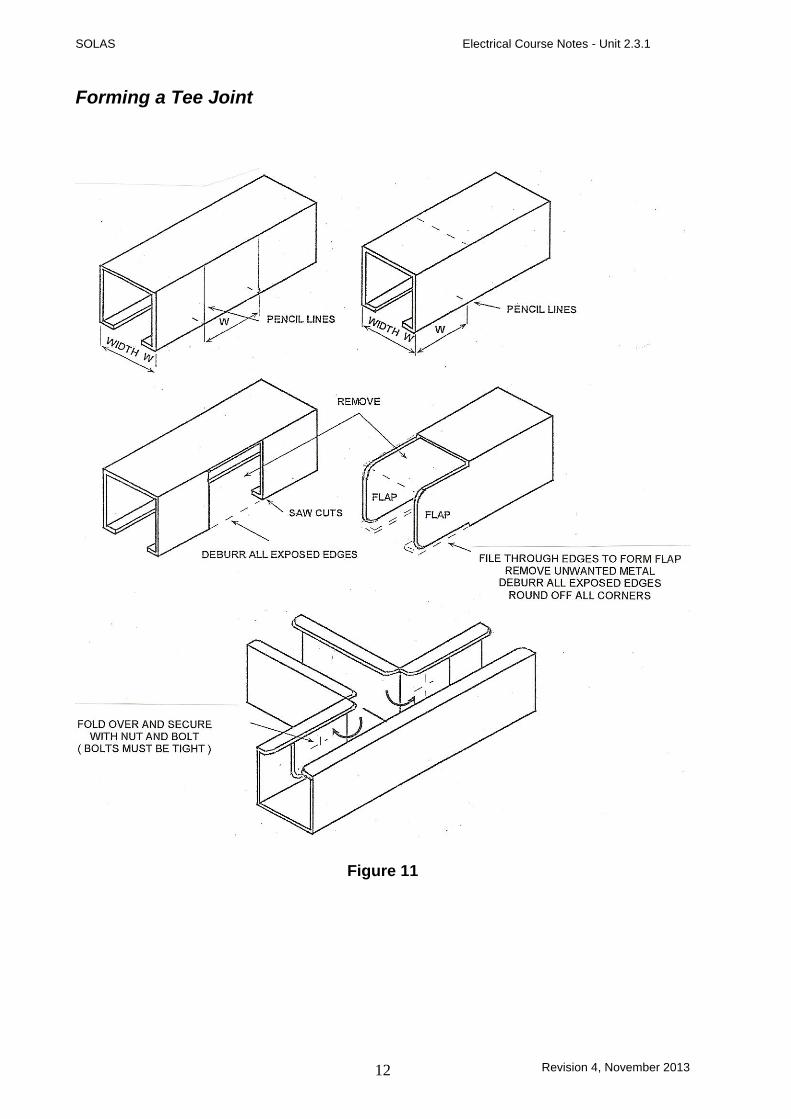
Fabrication and Installation of Tees and Bends
Tee and bends may be fabricated where required in lengths of trunking. This may be necessary
or simply more convenient, particularly if the required bend or set is non-standard. It takes more
time to fabricate tees or bends than to bolt on manufactured accessories.
Note-: It is recommended that a 32 TPI hacksaw blade be used for cutting steel trunking.
SOLAS Electrical Course Notes - Unit 2.3.1
Revision 4, November 2013 12
Forming a Tee Joint
Figure 11
SOLAS Electrical Course Notes - Unit 2.3.1
Revision 4, November 2013 13
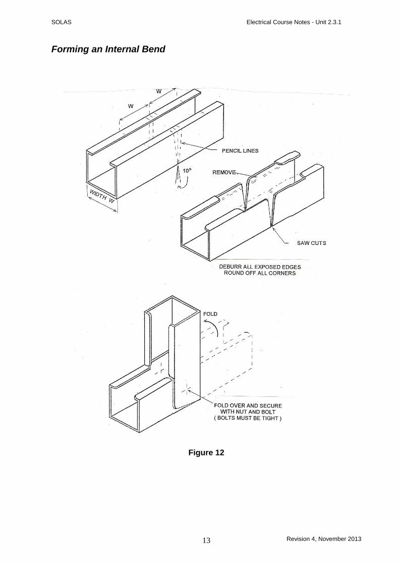
Forming an Internal Bend
Figure 12
SOLAS Electrical Course Notes - Unit 2.3.1
Revision 4, November 2013 14
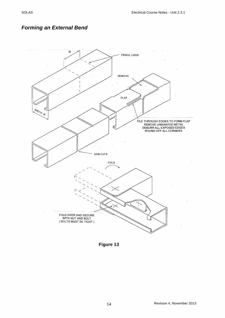
Forming an External Bend
Figure 13
SOLAS Electrical Course Notes - Unit 2.3.1
Revision 4, November 2013 15
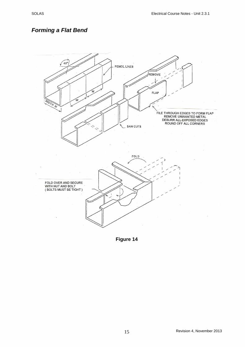
Forming a Flat Bend
Figure 14

SOLAS Electrical Course Notes - Unit 2.3.1
Revision 4, November 2013 16
Earthing of Steel Trunking
A trunking installation must be earthed. Earth continuity is ensured by the proper tightening of
all bolts used throughout the system. Some manufactures recommend that earth continuity be
completed by fixing a copper or aluminium strap across all joints. It is more important that all
the bolts involved in the system are tightened. It is not unusual to find that copper or aluminium
straps are used, but are left loose, resulting in poor earth continuity. See Figure 15.
Copper Earth Strap
Figure 15.
SOLAS Electrical Course Notes - Unit 2.3.1
Revision 4, November 2013 17
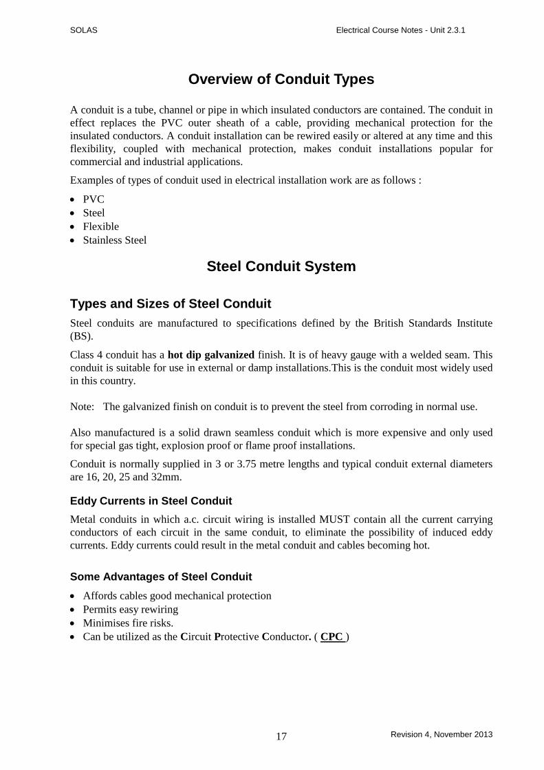
Overview of Conduit Types
A conduit is a tube, channel or pipe in which insulated conductors are contained. The conduit in
effect replaces the PVC outer sheath of a cable, providing mechanical protection for the
insulated conductors. A conduit installation can be rewired easily or altered at any time and this
flexibility, coupled with mechanical protection, makes conduit installations popular for
commercial and industrial applications.
Examples of types of conduit used in electrical installation work are as follows :
PVC
Steel
Flexible
Stainless Steel
Steel Conduit System
Types and Sizes of Steel Conduit
Steel conduits are manufactured to specifications defined by the British Standards Institute
(BS).
Class 4 conduit has a hot dip galvanized finish. It is of heavy gauge with a welded seam. This
conduit is suitable for use in external or damp installations.This is the conduit most widely used
in this country.
Note: The galvanized finish on conduit is to prevent the steel from corroding in normal use.
Also manufactured is a solid drawn seamless conduit which is more expensive and only used
for special gas tight, explosion proof or flame proof installations.
Conduit is normally supplied in 3 or 3.75 metre lengths and typical conduit external diameters
are 16, 20, 25 and 32mm.
Eddy Currents in Steel Conduit
Metal conduits in which a.c. circuit wiring is installed MUST contain all the current carrying
conductors of each circuit in the same conduit, to eliminate the possibility of induced eddy
currents. Eddy currents could result in the metal conduit and cables becoming hot.
Some Advantages of Steel Conduit
Affords cables good mechanical protection
Permits easy rewiring
Minimises fire risks.
Can be utilized as the Circuit Protective Conductor. ( CPC )

SOLAS Electrical Course Notes - Unit 2.3.1
Revision 4, November 2013 18
Some Disadvantages of Steel Conduit
Under certain conditions moisture is liable to form on the inside wall of the conduit.
Expensive compared with some other wiring systems.
Liable to corrosion where subject to acids, alkalis and corrosive fumes.
Cable Capacity of Steel Conduit ( Space Factor )
Having determined the correct number and cross-sectional area of cables for a given load it is
necessary to select the size of conduit that will accomodate them.
If a greater number of cables are installed in the conduit, over-heating, insulation damage and
fire may result. As a general rule the number of cables drawn into a conduit should not be such
as to cause damage to either the cables or the conduit during the installation.
The maximum number of cables which may be drawn into a conduit can be calculated by using
the factor system described in the ETCI Rules.
Cutting Steel Conduit
Conduit should be cut with a hacksaw, using a blade having 32 teeth / inch.
The cut should be made at right angles to avoid difficulty in threading the conduit.
Figure 1. illustrates this process.
Hold conduit to be cut securely in a pipe vice. Avoid damage to the galvanised coating.
Stand square to the job and make sure your movement is unobstructed.
Grip the hacksaw lightly and apply light pressure on the forward cutting stroke. Use the full
length of the blade.
Figure 1.
SOLAS Electrical Course Notes - Unit 2.3.1
Revision 4, November 2013 19
Threading Steel Conduit
It is necessary to cut threads on the conduit ends in order to screw them into conduit couplings
and accessory boxes. The conduit ends are threaded using stocks and dies. After threading the
ends, all internal burrs must be removed to ensure that cables are not damaged as they are
being drawn into the conduits.
All threaded ends must be screwed up tightly into accessories to ensure earth continuity.
Hold the conduit securely in a pipe vice ( ensure that pipe vice jaw bolts are tight ).
While threading keep the die well lubricated preferably with a manufacturer’s paste or
tallow.
Thread to required length and remove any burrs with a file or reamer, this will prevent
sharp edges causing damage to cables while being drawn into the conduit.
To ensure a clean, unbroken thread the die should be rotated counter-clockwise frequently
and finally run up and down the threads to remove any swarf ( metal fragments ).
Fitting and Fixing Steel Conduit
Conduit must be securely fixed and where it is liable to mechanical damage, it should be
suitably protected.
Drainage outlets must be provided at points where condensation is likely to collect.
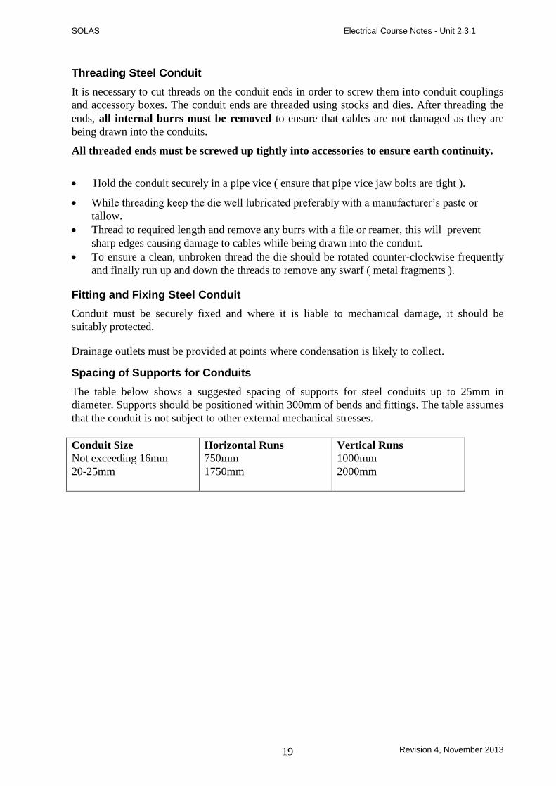
Spacing of Supports for Conduits
The table below shows a suggested spacing of supports for steel conduits up to 25mm in
diameter. Supports should be positioned within 300mm of bends and fittings. The table assumes
that the conduit is not subject to other external mechanical stresses.
Conduit Size
Not exceeding 16mm
20-25mm
Horizontal Runs
750mm
1750mm
Vertical Runs
1000mm
2000mm

SOLAS Electrical Course Notes - Unit 2.3.1
Revision 4, November 2013 20
Saddles
A range of clips and saddles are available for conduit installations. The spacer bar saddle, is the
device most commonly used for fixing conduit, see Figure 2. They provide a very secure
method of fixing and generally should be spaced as per the table on the previous page.
Figure 2.
Spacer bar saddles incorporate a spacing plate. These spacing plates are approximately 5mm
thick. This spacing plate tends to align the conduit with the knockouts in switch and socket
outlet boxes. On vertical runs ensure that saddles are fitted the correct way round. An important
function of the spacer bar saddle is to keep the conduit out of contact with plaster and cement
surfaces. Contact between conduit and these surfaces could result in corrosion of the conduit
and discolourment of the surfaces.
When a conduit is fixed to concrete, much installation time is spent in plugging the concrete for
fixings. Spacer bar saddles have the advantage of a central, single-hole fixing. The additional
cost of spacer bar saddles over the plain saddle (see Figure 3.) can be offset against the saving in
time and effort required in fixing.
Figure 3.

SOLAS Electrical Course Notes - Unit 2.3.1
Revision 4, November 2013 21
Distance Saddles
Distance saddles are designed to space the conduit approximately 10mm from the wall or
ceiling. These saddles are generally made of malleable cast iron. They are much more
substantial than spacer bar saddles and the additional spacing provides greater protection against
corrosion. The use of distance saddles eliminates the possibility of dust and dirt collecting
behind the conduit. By adequate spacing it is possible to keep the conduits free of dust and it is
for this reason distance saddles (Figure 4A) and hospital saddles (Figure 4B) are generally
specified.
Figure 4A Figure 4B
Multiple Saddles
Where two or more conduits follow the same route it is generally an advantage to use multiple
saddles, see Figure 5. Proper spacing of the conduits ensures that there is no need to set the
conduits where they enter conduit accessories
Figure 5
SOLAS Electrical Course Notes - Unit 2.3.1
Revision 4, November 2013 22
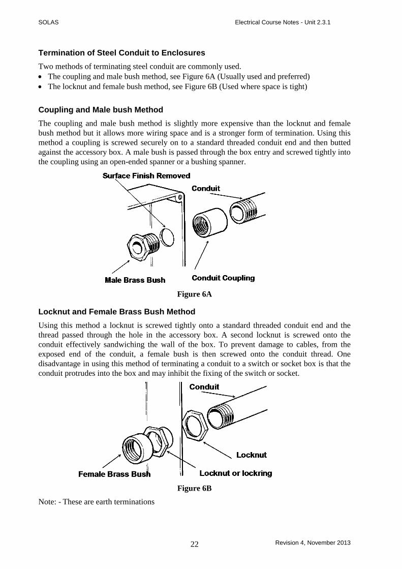
Termination of Steel Conduit to Enclosures
Two methods of terminating steel conduit are commonly used.
The coupling and male bush method, see Figure 6A (Usually used and preferred)
The locknut and female bush method, see Figure 6B (Used where space is tight)
Coupling and Male bush Method
The coupling and male bush method is slightly more expensive than the locknut and female
bush method but it allows more wiring space and is a stronger form of termination. Using this
method a coupling is screwed securely on to a standard threaded conduit end and then butted
against the accessory box. A male bush is passed through the box entry and screwed tightly into
the coupling using an open-ended spanner or a bushing spanner.
Figure 6A
Locknut and Female Brass Bush Method
Using this method a locknut is screwed tightly onto a standard threaded conduit end and the
thread passed through the hole in the accessory box. A second locknut is screwed onto the
conduit effectively sandwiching the wall of the box. To prevent damage to cables, from the
exposed end of the conduit, a female bush is then screwed onto the conduit thread. One
disadvantage in using this method of terminating a conduit to a switch or socket box is that the
conduit protrudes into the box and may inhibit the fixing of the switch or socket.
Figure 6B
Note: - These are earth terminations
SOLAS Electrical Course Notes - Unit 2.3.1
Revision 4, November 2013 23
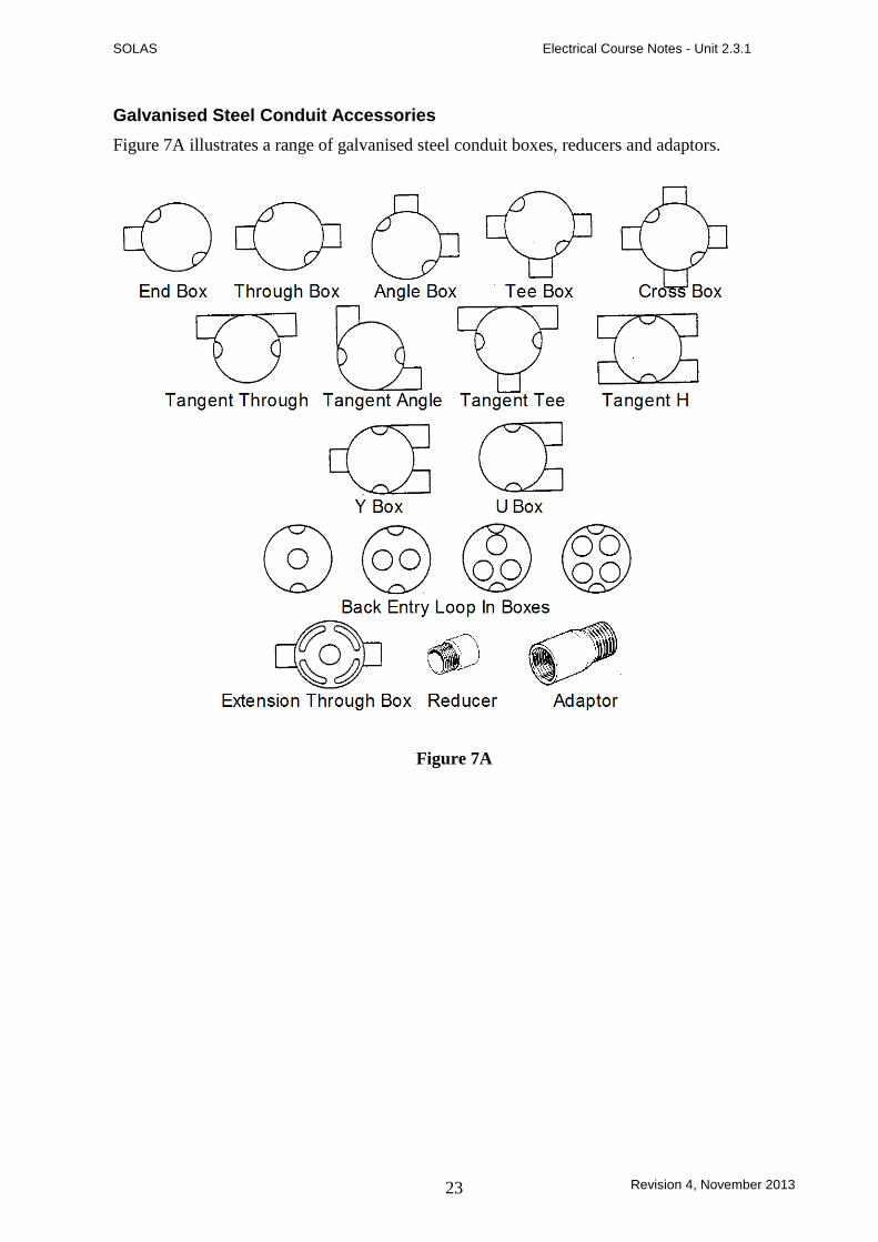
Galvanised Steel Conduit Accessories
Figure 7A illustrates a range of galvanised steel conduit boxes, reducers and adaptors.
Figure 7A
SOLAS Electrical Course Notes - Unit 2.3.1
Revision 4, November 2013 24
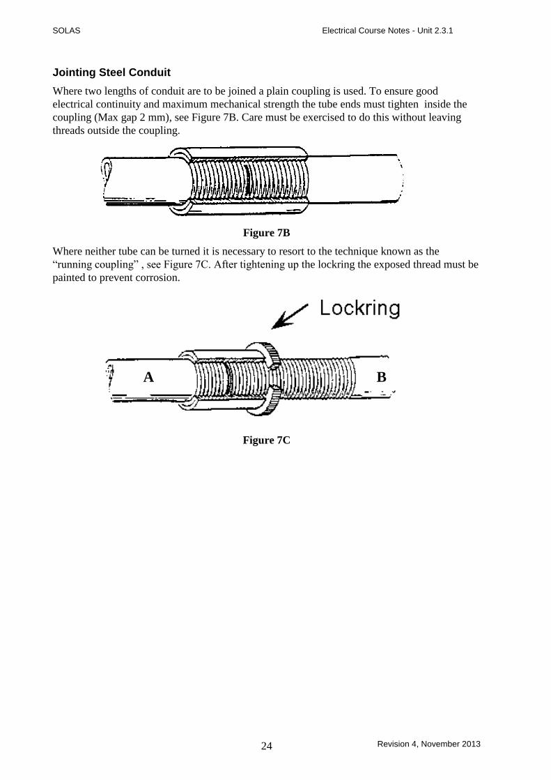
Jointing Steel Conduit
Where two lengths of conduit are to be joined a plain coupling is used. To ensure good
electrical continuity and maximum mechanical strength the tube ends must tighten inside the
coupling (Max gap 2 mm), see Figure 7B. Care must be exercised to do this without leaving
threads outside the coupling.
Figure 7B
Where neither tube can be turned it is necessary to resort to the technique known as the
“running coupling” , see Figure 7C. After tightening up the lockring the exposed thread must be
painted to prevent corrosion.
A B
Figure 7C

SOLAS Electrical Course Notes - Unit 2.3.1
Revision 4, November 2013 25
Setting up Sequence of a Bending Machine
Place the semi-circular former ‘B’ (to suit the size of conduit to be bent) in position and
secure the centre-pin, see Figure 8.
Figure 8.
Position the stop ‘C’ in the correct position for size of conduit, see Figure 9.
Figure 9.
Insert the grooved roller in the correct position for size of conduit, see Figure 10.
Figure 10.

SOLAS Electrical Course Notes - Unit 2.3.1
Revision 4, November 2013 26
Bending Steel Conduit
The most common method of bending steel conduit is to use a bending machine. However, for
bending 32mm diameter or larger conduits it is recommended to use a portable ratchet bender.
The following are the main steps to be taken when using a bending machine.
Insert the conduit under the stop and into the groove in the former.
Pull down the handle, allowing the roller to bend the conduit around the former.
Use a template to compare the angle of the bend formed with the desired angle.
Bends should be formed to an internal radius of not less than 2.5 times the
conduit diameter
Making a 90o Bend in Steel Conduit
Figure 11 illustrates a right angle bend in steel conduit, which must be formed to a dimension of
200mm.
200mm
Figure 11.
The first step is to mark off 200mm from the end of the conduit as illustrated in Figure 12.
Mark 200mm from Fixed Point
Fixed Point Marked Point
Figure 12.

SOLAS Electrical Course Notes - Unit 2.3.1
Revision 4, November 2013 27
The next step is to place the conduit in the former with the mark to the rear. Position the conduit
so that a try-square, held against the mark touches and forms a tangent to the edge of the former
as illustrated in Figure 13.
Stop Fixed Point
Marked Point
Bend down
to 90 0
Figure 13.
Next pull the lever down until the 90° angle, is achieved.

SOLAS Electrical Course Notes - Unit 2.3.1
Revision 4, November 2013 28
Making a Double Set or Offset in Steel Conduit
Normally offsets should be formed at either 30° or 45°.
A 30° offset is preferred for two reasons:
Ease of measurement.
Ease of drawing-in cables.
Forming of a 30° Offset
Figure 14 illustrates a 30° offset to be formed in steel conduit. From the illustration it can be
seen that the 30° angle is one of three angles forming a right angled triangle.
60 0
90 0 30
0
100mm
Figure 14.
A rule of thumb for a right angle triangle (30°, 60°, 90°) states that the relationship between the
three sides is in the ratio of 1:2:3, see Figure 15.
2
1
3
Figure 15.
With this information, once we know the dimension of the offset (100mm in this case) we can
now calculate and mark off the distance between the two bends. At this point take the straight
piece of conduit and mark on it where you want the first bend to start from, then measure
200mm from that point to where the second bend starts, see Figure 16.
1st 2nd
200mm
Figure 16.
SOLAS Electrical Course Notes - Unit 2.3.1
Revision 4, November 2013 29
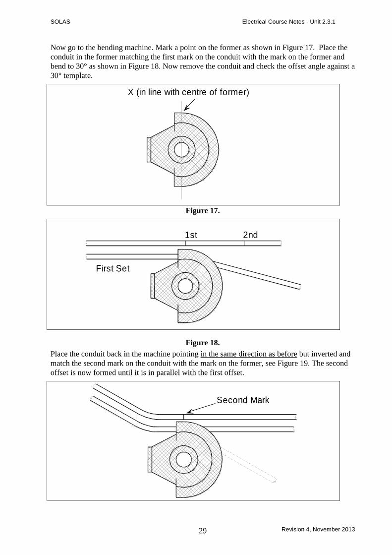
Now go to the bending machine. Mark a point on the former as shown in Figure 17. Place the
conduit in the former matching the first mark on the conduit with the mark on the former and
bend to 30° as shown in Figure 18. Now remove the conduit and check the offset angle against a
30° template.
X (in line with centre of former)
Figure 17.
1st 2nd
First Set
Figure 18.
Place the conduit back in the machine pointing in the same direction as before but inverted and
match the second mark on the conduit with the mark on the former, see Figure 19. The second
offset is now formed until it is in parallel with the first offset.
Second Mark

SOLAS Electrical Course Notes - Unit 2.3.1
Revision 4, November 2013 30
Forming a 45° Offset
A 45° degree offset is formed in exactly the same manner as the 30° version except that the
measurements between the first and second bends are calculated using the following formula
1:1:2. Figure 20 illustrates the use of this formula, in this case 2 =141mm or 100 x 2 =
141mm.
1
12100mm141m
m
Figure 20.
SOLAS Electrical Course Notes - Unit 2.3.1
Revision 4, November 2013 31
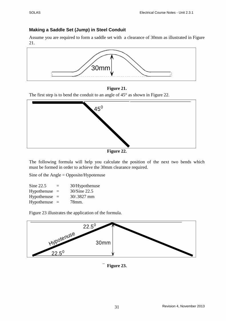
Making a Saddle Set (Jump) in Steel Conduit
Assume you are required to form a saddle set with a clearance of 30mm as illustrated in Figure
21.
30mm
Figure 21.
The first step is to bend the conduit to an angle of 45° as shown in Figure 22.
450
Figure 22.
The following formula will help you calculate the position of the next two bends which
must be formed in order to achieve the 30mm clearance required.
Sine of the Angle = Opposite/Hypotenuse
Sine 22.5 = 30/Hypothenuse
Hypothenuse = 30/Sine 22.5
Hypothenuse = 30/.3827 mm
Hypothenuse = 78mm.
Figure 23 illustrates the application of the formula.
22.50
22.50
Hypotenuse
30mm
Figure 23.

SOLAS Electrical Course Notes - Unit 2.3.1
Revision 4, November 2013 32
Mark the conduit as shown in Figure 24.
Mark 2 at 78mmfrom Mark 130mm
3 2
1
Mark 1 The centre of
the existing 450 bend
Mark 3 at 78mmfrom Mark 1
Figure 24.
Marks 2 and 3 may also be located using a straight edge or other method.
Place the conduit in the machine so that mark 2 is opposite the existing mark on the former, and
bend downwards as shown in Figure 25.
Mark 2 on conduit
Former Mark
Mark 3
Mark 1
SecondSet
Figure25.
SOLAS Electrical Course Notes - Unit 2.3.1
Revision 4, November 2013 33
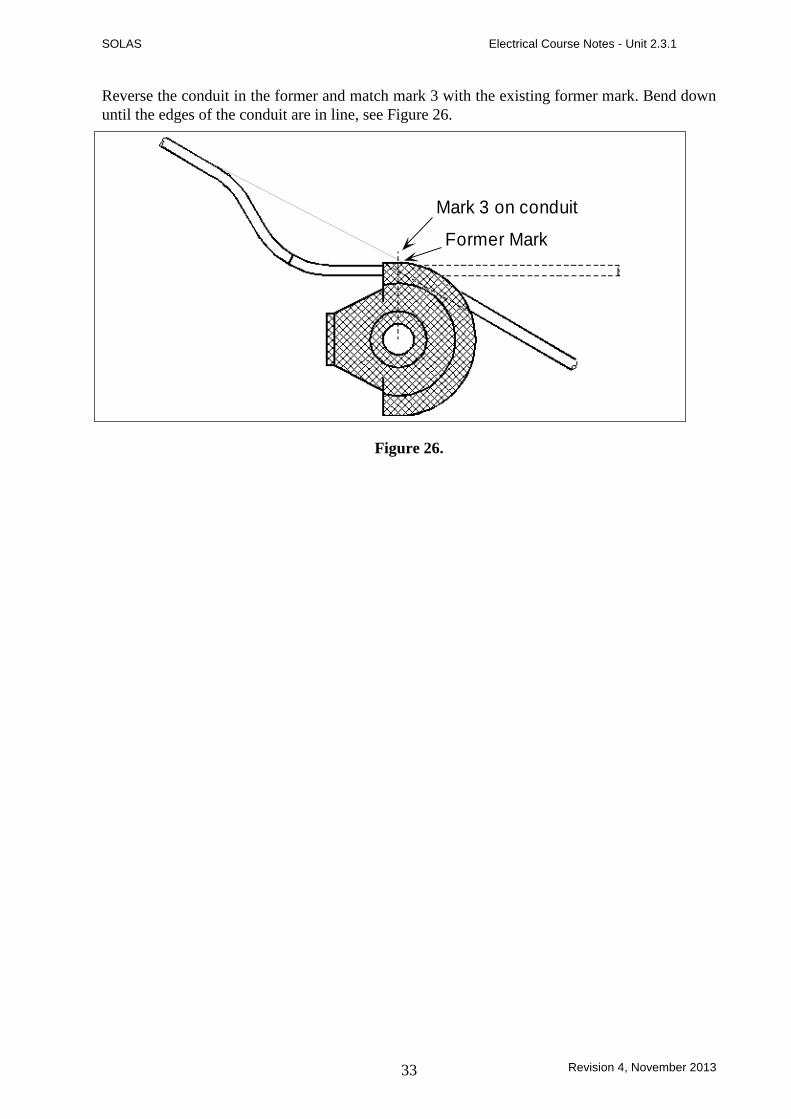
Reverse the conduit in the former and match mark 3 with the existing former mark. Bend down
until the edges of the conduit are in line, see Figure 26.
Mark 3 on conduit
Former Mark
Figure 26.

SOLAS Electrical Course Notes - Unit 2.3.1
Revision 4, November 2013 34
Making a Double 90o Bend in Steel Conduit
Measurements for a double 90° bend in steel conduit can be taken using any of the three
methods shown in Figure 27.
Centre to Centre
Outside to Inside
Inside to Outside
All are 200mm
Figure 27.
If you add the outside diameter of the conduit (20mm) to the centre to centre measurments
(200mm) we can now mark the position of the second bend (220mm), see Figure 28. Bend
down until the 900 angle is achieved.
220mm
200mm Centre to Centre
Figure 28.
Note: - The above methods may require adjustments due to manufacturer’s tolerances and wear
in different bending machines

SOLAS Electrical Course Notes - Unit 2.3.1
Revision 4, November 2013 35
PVC Conduit
Composition of PVC Conduit
The basic material is poly-vinyl-chloride ( PVC ) which is produced in both flexible and rigid
forms. It is impervious to acids, alkalis, oil, aggressive soils, fungi and bacteria and is
unaffected by sea, and air. It withstands all pests and does not attract rodents.
PVC conduit may be buried in lime, concrete or plaster without harmful effects.
Choice of PVC Conduit
The choice is dependant on the type of work being undertaken and the job specification.
Heavy gauge round conduit is normally used in surface work and for forming on-site.
Light gauge round conduit is suitable for concealed work.
Oval conduit is normally chosen for use in plaster walls and can be used for drops in surface
work.
Typical electrical installations use a heavy guage standard impact tube manufactured to BS
4607. The conduit sizes and range of fittings are the same as those available for metal conduit.
Jointing PVC Conduit
PVC conduit is most often jointed by placing the end of the conduit into the appropriate fitting.
Joints into accessories can be easily made dry or by the use of silicone grease or a permanent
solvent, dependant on the installation conditions. The silicone grease should be used for
expansion couplings and where an installation may be subject to future alteration.
Precautions When Using Adhesives
Care should be taken when using adhesives, which are pro-chemical based, and as such are
quite flammable and volatile.
Replace the lid on the tin immediately after use.
Use in a ventilated area away from naked flame.
Under no circumstance should you smoke while working with this adhesive.
If adhesive should get into your eyes, seek first-aid immediately.
Expansion of PVC Conduit
Expansion couplings should be used for surface installations at a recommended maximum of 4
metre intervals.
Where frequent variations in ambient temperature are likely to occur this distance must be
greatly reduced.
Note: PVC conduit is not suitable for installations subject to temperatures below -5oC or above
65oC

SOLAS Electrical Course Notes - Unit 2.3.1
Revision 4, November 2013 36
Fitting and Fixing of PVC Conduit
A range of fixings for PVC conduit is available as shown in Figure 29.
Figure 29.
PVC conduit is fixed in the same way as metal conduit. All horizontal runs should be saddled at
not more than 900 mm intervals unless high ambient temperatures or rapid changes in
temperature are likely to be encountered, when the intervals should be reduced.
Vertical runs should be saddled at not more than 1200 mm intervals except where directional
changes are made. Saddles should be installed approximately 150 mm either side of a bend.
Conduit should be able to move freely in the saddle.
Advantages of PVC Conduit
Lightweight and easy to handle
Easy to cut and deburr
Simple to form and bend
Does not require painting
Minimal condensation due to low thermal conductivity in wall of conduit.
Speed of installation
Excellent electrical and fire resistant properties
Disadvantages of PVC Conduit
Care must be taken when glueing joints to avoid forming a barrier across the inside of the
conduit.
If insufficent adhesive is used the joints may not be waterproof.
PVC expands about 5 times as much as steel and this expansion must be allowed for.
PVC does not offer the same level of mechanical protection as steel.
A separate Circuit Protective Conductor must be run inside the conduit.
SOLAS Electrical Course Notes - Unit 2.3.1
Revision 4, November 2013 37
Working with PVC Conduit
PVC conduit is easily cut using a junior hack saw. Any roughness of cut and burrs should be
removed with the aid of knife blade or simply by wiping with a cloth. There are proprietary
tools available for cutting PVC conduit.
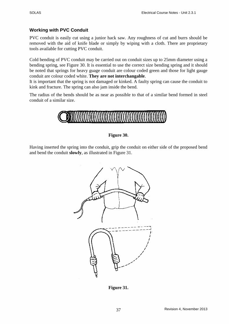
Cold bending of PVC conduit may be carried out on conduit sizes up to 25mm diameter using a
bending spring, see Figure 30. It is essential to use the correct size bending spring and it should
be noted that springs for heavy guage conduit are colour coded green and those for light gauge
conduit are colour coded white. They are not interchangable.
It is important that the spring is not damaged or kinked. A faulty spring can cause the conduit to
kink and fracture. The spring can also jam inside the bend.
The radius of the bends should be as near as possible to that of a similar bend formed in steel
conduit of a similar size.
Figure 30.
Having inserted the spring into the conduit, grip the conduit on either side of the proposed bend
and bend the conduit slowly, as illustrated in Figure 31.
Figure 31.

SOLAS Electrical Course Notes - Unit 2.3.1
Revision 4, November 2013 38
The conduit should be bent to a more acute angle than the angle finally desired because of the
tendency of PVC to “recover” after bending. This tendency lessens as the temperature
decreases.
In very cold weather it is recommended that the conduit is warmed slightly by rubbing with a
cloth held in the hand. If the conduit is bent too quickly there is a risk of kinking and / or
fracturing of the conduit and possible damage to the bending spring.
If the conduit is intended for surface work it should be saddled and fixed as soon as possible
after bending. Once a bend has been formed it should not be forced backwards as this can
damage both the conduit and the spring.
To remove the spring, twist it in an anti-clockwise direction. This will reduce the diameter of
the spring and make it possible to pull the conduit and spring apart. If the spring jams during
this operation do not pull hard on it, otherwise the spring will be damaged.
Hot Bending of PVC Conduit
Hot bending of conduit should be carried out on sizes over 25mm diameter. A bending spring of
the correct size should be used. Apply a gentle heat preferrably with a hot air torch, electric
heating element or hot water. Bend the conduit in accordance with above instructions and Fig.
31.
Care should be taken to avoid the direct application of flame to the conduit. When the conduit is
in a pliable state it should be slowly bent around a suitable former and held in position for about
one minute until set. After setting, the bending spring may be twisted anti-clockwise and
removed.

SOLAS Electrical Course Notes - Unit 2.3.1
Revision 4, November 2013 39
Unit Related ETCI Rules
Types of Wiring System 521
521.5, 521.5.1, 521.5.2
521.6, 521.6.1, 521.6.2, 521.6.3
521.6.4, 521.6.5
521.10
Selection and Erection in Relation to
External Influences
522
522.3.2
522.8.2, 522.8.5, 522.8.6, 522.8.11
Electrical Connections 526
526.2.3
526.3.3
Selection and Erection of Wiring
Systems to minimise the spread of Fire
527
527.1.2, 527.1.3 ( item 2 )
527.2, 527.2.1, 527.2.2, 527.2.3
Precautions against Detrimental Effects
from Adjacent Services
528
528.1, 528.1.1 items a, c, and e
Protective Conductors 543
543.2.1 ( items 2 and 6 ), 543.2.4
Annex 52A
52B-2 ( item 3 )
Tables U
V
W
X
Y
Z


