126
Conext™ XW Inverter/Charger Owner’s Guide 975-0713-01-01 Rev B July 2015 solar.schneider-electric.com Conext XW+ 7048 E Conext XW+ 8548 E

XW_Europe_Operation.book Page i Thursday, July 30, 2015 4:12 PM
Conext™ XW Inverter/Charger
Owner’s Guide975-0713-01-01 Rev BJuly 2015
solar.schneider-electric.com
Conext XW+ 7048 EConext XW+ 8548 E

XW_Europe_Operation.book Page ii Thursday, July 30, 2015 4:12 PM

XW_Europe_Operation.book Page i Thursday, July 30, 2015 4:12 PM
Conext™ XW Inverter/Charger
Owner’s Guide
solar.schneider-electric.com

XW_Europe_Operation.book Page ii Thursday, July 30, 2015 4:12 PM
Copyright and Contact
Copyright © 2007-2015 Schneider Electric. All Rights Reserved.
All trademarks are owned by Schneider Electric Industries SAS or its affiliated companies.
Exclusion for DocumentationUNLESS SPECIFICALLY AGREED TO IN WRITING, SELLER
(A) MAKES NO WARRANTY AS TO THE ACCURACY, SUFFICIENCY OR SUITABILITY OF ANY TECHNICAL OR OTHER INFORMATION PROVIDED IN ITS MANUALS OR OTHER DOCUMENTATION;(B) ASSUMES NO RESPONSIBILITY OR LIABILITY FOR LOSSES, DAMAGES, COSTS OR EXPENSES, WHETHER SPECIAL, DIRECT, INDIRECT, CONSEQUENTIAL OR INCIDENTAL, WHICH MIGHT ARISE OUT OF THE USE OF SUCH INFORMATION. THE USE OF ANY SUCH INFORMATION WILL BE ENTIRELY AT THE USER’S RISK; AND
(C) REMINDS YOU THAT IF THIS MANUAL IS IN ANY LANGUAGE OTHER THAN ENGLISH, ALTHOUGH STEPS HAVE BEEN TAKEN TO MAINTAIN THE ACCURACY OF THE TRANSLATION, THE ACCURACY CANNOT BE GUARANTEED. APPROVED CONTENT IS CONTAINED WITH THE ENGLISH LANGUAGE VERSION WHICH IS POSTED AT SOLAR.SCHNEIDER-ELECTRIC.COM.
Date and RevisionJuly 2015 Rev B
Document Part Number975-0713-01-01
Product Part Numbers
Contact Information
solar.schneider-electric.com
Please contact your local Schneider Electric Sales Representative or visit our website at:http://solar.schneider-electric.com/tech-support/
Information About Your SystemAs soon as you open your product, record the following information and be sure to keep your proof of purchase.
Product Part Numbers Related Product Part Numbers865-8548-61 – Conext XW+ 8548 E 865-1014-01 – Conext XW+ Power Distribution Panel (without
breakers)865-7048-61 – Conext XW+ 7048 E 865-1025 – Conext XW+ Conduit Box
865-1020-01 – Conext XW+ Connection Kit for INV2 INV3 PDP865-1030-1 – Conext MPPT 60 150 Solar Charge Controller865-1032 – Conext MPPT 80 600 Solar Charge Controller865-1050-01 – Conext System Control Panel865-1060-01 – Conext Automatic Generator Start865-1058-01 – Conext ComBox865-1031-01 – Battery Fuse Disconnect Box (250A)865-1030-01 – Battery Fuse Disconnect Box (160A)
Serial Number _________________________________
Product Number _________________________________
Purchased From _________________________________
Purchase Date _________________________________

XW_Europe_Operation.book Page iii Thursday, July 30, 2015 4:12 PM
About This Guide
Purpose
The purpose of this Owner’s Guide is to provide the information and procedures necessary for configuring, operating, maintaining, and troubleshooting the Schneider Electric Conext XW+ Inverter/Charger
Scope
This Guide includes information about monitoring and configuring the Conext XW+ Inverter/Charger.
This Guide provides guidelines, detailed setup information, and information about operating and troubleshooting the unit. It does not provide installation procedures or details about particular brands of batteries, photoelectric cells, or generators. Consult the equipment manufacturers for this information.
Audience
This Guide is intended for anyone who needs to operate, configure, and troubleshoot the Conext XW+ Inverter/Charger. Certain configuration tasks should only be performed by qualified personnel in consultation with your local utility and/or an authorized dealer. Electrical equipment should be installed, operated, serviced, and maintained only by qualified personnel. Servicing of batteries must only be performed or supervised by qualified personnel with knowledge of batteries and their required precautions. Qualified personnel have training, knowledge, and experience in:
• Installing electrical equipment
• Applying applicable installation codes
• Analyzing and reducing the hazards involved in performing electrical work
• Installing and configuring batteries
• Selecting and using Personal Protective Equipment (PPE)
No responsibility is assumed by Schneider Electric for any consequences arising out of the use of this material.
Organization
This Guide is organized into four chapters and two appendices.
Chapter 1, “Introduction”, describes the operating features of the Conext XW+ Inverter/Charger.
iii

About This Guide
XW_Europe_Operation.book Page iv Thursday, July 30, 2015 4:12 PM
Chapter 2, “Monitoring Operation”, contains information about monitoring Conext XW+ Inverter/Charger operation using the inverter information panel or the Xanbus System Control Panel.
Chapter 3, “Configuration” explains how to navigate through the Xanbus System Control Panel menus and configure the Conext XW+ Inverter/Charger.,
Chapter 4, “Troubleshooting”, contains information and procedures for identifying and solving possible problems with the Conext XW+ Inverter/Charger.
Appendix A, “Specifications” provides the electrical and mechanical specifications for the Conext XW+ Inverter/Charger.
Appendix B contains the default configuration settings and ranges for the Conext XW+ Inverter/Charger. Configuration settings can be viewed and changed using the Xanbus System Control Panel.
Related Information
For information about installing the Xantrex XW Inverter/Charger, see the Conext XW+ Inverter/Charger Installation Guide (975-0714-01-01).
For more information about Schneider Electric as well as its products and services, visit solar.schneider-electric.com/solar.
iv 975-0713-01-01

XW_Europe_Operation.book Page v Thursday, July 30, 2015 4:12 PM
Important Safety Instructions
READ AND SAVE THESE INSTRUCTIONS - DO NOT DISCARD
This guide contains important safety instructions for the Conext XW+ Inverter/Charger that must be followed during operation and troubleshooting. Read and keep this Owner’s Guide for future reference.
Read these instructions carefully and look at the equipment to become familiar with the device before trying to install, operate, service or maintain it. The following special messages may appear throughout this bulletin or on the equipment to warn of potential hazards or to call attention to information that clarifies or simplifies a procedure.
The addition of either symbol to a “Danger” or “Warning” safety label indicates that an electrical hazard exists which will result in personal injury if the instructions are not followed.
This is the safety alert symbol. It is used to alert you to potential personal injury hazards. Obey all safety messages that follow this symbol to avoid possible injury or death.
DANGER
DANGER indicates a hazardous situation which, if not avoided, will result in death or serious injury.
WARNING
WARNING indicates a hazardous situation which, if not avoided, could result in death or serious injury.
CAUTION
CAUTION indicates a hazardous situation which, if not avoided, could result in minor or moderate injury.
NOTICE
NOTICE is used to address practices not related to physical injury. The safety alert symbol shall not be used with this signal word.
v

vi
XW_Europe_Operation.book Page vi Thursday, July 30, 2015 4:12 PM
Safety Information
1. Before using the inverter, read all instructions and cautionary markings on the unit, the batteries, and all appropriate sections of this manual.
2. Use of accessories not recommended or sold by the manufacturer may result in a risk of fire, electric shock, or injury to persons.
3. The inverter is designed to be permanently connected to your AC and DC electrical systems. The manufacturer recommends that all wiring be done by a certified technician or electrician to ensure adherence to the local and national electrical codes applicable in your jurisdiction.
4. To avoid a risk of fire and electric shock, make sure that existing wiring is in good condition and that wire is not undersized. Do not operate the inverter with damaged or substandard wiring.
5. Do not operate the inverter if it has been damaged in any way.
6. This unit does not have any user-serviceable parts. Do not disassemble the inverter except where noted for connecting wiring and cabling. See your warranty for instructions on obtaining service. Attempting to service the unit yourself may result in a risk of electrical shock or fire. Internal capacitors remain charged after all power is disconnected.
7. To reduce the risk of electrical shock, disconnect both AC and DC power from the inverter before attempting any maintenance or cleaning or working on any components connected to the inverter. Putting the unit in Standby mode will not reduce this risk.
8. The inverter must be provided with an equipment-grounding conductor connected to the AC input ground.
9. Do not expose this unit to rain, snow, or liquids of any type. This product is designed for indoor use only. Damp environments will significantly shorten the life of this product and corrosion caused by dampness will not be covered by the product warranty.
10. To reduce the chance of short-circuits, always use insulated tools when installing or working with this equipment.
11. Remove personal metal items such as rings, bracelets, necklaces, and watches when working with electrical equipment.

XW_Europe_Operation.book Page vii Thursday, July 30, 2015 4:12 PM
DANGER
HAZARD OF ELECTRIC SHOCK, EXPLOSION, OR ARC FLASH
• Apply appropriate personal protective equipment (PPE) and follow safe electrical work practices. See NFPA 70E or CSA Z462.
• This equipment must only be installed and serviced by qualified electrical personnel.
• Never operate energized with covers removed
• Energized from multiple sources. Before removing covers identify all sources, de-energize, lock-out, and tag-out and wait 2 minutes for circuits to discharge
• Always use a properly rated voltage sensing device to confirm all circuits are de-energized.
Failure to follow these instructions will result in death or serious injury.
DANGER
HAZARD OF ELECTRIC SHOCK, EXPLOSION, OR ARC FLASH
• Remove watches, rings, or other metal objects.
• This equipment must only be installed and serviced by qualified electrical personnel.
• Keep sparks and flames away from the batteries.
• Use tools with insulated handles.
• Wear protective glasses, gloves and boots.
• Do not lay tools or other metal parts on top of batteries.
Failure to follow these instructions will result in death or serious injury.
975-0713-01-01 vii

XW_Europe_Operation.book Page viii Thursday, July 30, 2015 4:12 PM
Limitations on Use
Explosive Gas Precautions
Working in the vicinity of lead acid batteries is dangerous. Batteries generate explosive gases during normal operation. Therefore, you must read this Guide and follow the instructions exactly before installing or using your inverter/charger.
To reduce the risk of battery explosion, follow these instructions and those published by the battery manufacturer and the manufacturer of the equipment in which the battery is installed.
DANGER
HAZARD OF ELECTRIC SHOCK, EXPLOSION, OR ARC FLASH
• Battery Circuit Breakers must be installed according to the specifications and requirements defined by Schneider Electric.s.
• Servicing of batteries must only be performed by qualified personnel knowledgeable about batteries and the required precautions. Keep unqualified personnel away from batteries.
• Disconnect the charging source prior to connecting or disconnecting battery terminals.
Failure to follow these instructions will result in death or serious injury.
WARNING
LIMITATIONS ON USE
The Conext XW+ Inverter/Charger is not intended for use in connection with life support systems or other medical equipment or devices.
Failure to follow these instructions can result in death or serious injury.
WARNING
EXPLOSION HAZARD
This equipment is not ignition protected. To prevent fire or explosion, do not install this product in locations that require ignition-protected equipment. This includes any space containing gasoline-powered machinery, fuel tanks, as well as joints, fittings, or other connections between components of the fuel system.
Failure to follow these instructions can result in death or serious injury.
viii 975-0713-01-01
XW_Europe_Operation.book Page ix Thursday, July 30, 2015 4:12 PM
FCC Information to the User
This equipment has been tested and found to comply with the limits for a Class B digital device, pursuant to part 15 of the FCC Rules. These limits are designed to provide reasonable protection against harmful interference in a residential installation. This equipment generates, uses and can radiate radio frequency energy and, if not installed and used in accordance with the instructions, may cause harmful interference to radio communications. However, there is no guarantee that interference will not occur in a particular installation. If this equipment does cause harmful interference to radio or television reception, which can be determined by turning the equipment off and on, the user is encouraged to try to correct the interference by one or more of the following measures:
• Reorient or relocate the receiving antenna.
• Increase the separation between the equipment and the receiver.
• Connect the equipment to a circuit different from that to which the receiver is connected.
• Consult the dealer or an experienced radio/TV technician for help.
975-0713-01-01 ix

x
XW_Europe_Operation.book Page x Thursday, July 30, 2015 4:12 PM

Contents
XW_Europe_Operation.book Page xi Thursday, July 30, 2015 4:12 PM
Important Safety Instructions
1 IntroductionFeatures - - - - - - - - - - - - - - - - - - - - - - - - - - - - - - - - - - - - - - - - - - - - - - - - - - - - - - - - - - - - - - - 1–2
Performance Highlights - - - - - - - - - - - - - - - - - - - - - - - - - - - - - - - - - - - - - - - - - - - - - - - - - - 1–2Distinguishing Features - - - - - - - - - - - - - - - - - - - - - - - - - - - - - - - - - - - - - - - - - - - - - - - - - - 1–2
Xanbus™ Network Communications Protocol - - - - - - - - - - - - - - - - - - - - - - - - - - - - - - - - 1–2Available Conext XW+ Accessories - - - - - - - - - - - - - - - - - - - - - - - - - - - - - - - - - - - - - - - - - - 1–3
Operation - - - - - - - - - - - - - - - - - - - - - - - - - - - - - - - - - - - - - - - - - - - - - - - - - - - - - - - - - - - - - - 1–3Bidirectional Theory of Operation - - - - - - - - - - - - - - - - - - - - - - - - - - - - - - - - - - - - - - - - - - - 1–3Surge Performance - - - - - - - - - - - - - - - - - - - - - - - - - - - - - - - - - - - - - - - - - - - - - - - - - - - - - 1–6Islanding Protection - - - - - - - - - - - - - - - - - - - - - - - - - - - - - - - - - - - - - - - - - - - - - - - - - - - - - 1–6AC Coupling - - - - - - - - - - - - - - - - - - - - - - - - - - - - - - - - - - - - - - - - - - - - - - - - - - - - - - - - - - 1–7Multi-unit Operation - - - - - - - - - - - - - - - - - - - - - - - - - - - - - - - - - - - - - - - - - - - - - - - - - - - - - 1–8Auxiliary Output - - - - - - - - - - - - - - - - - - - - - - - - - - - - - - - - - - - - - - - - - - - - - - - - - - - - - - - 1–10Transfer Relay - - - - - - - - - - - - - - - - - - - - - - - - - - - - - - - - - - - - - - - - - - - - - - - - - - - - - - - - 1–10K1 and K2 relay - - - - - - - - - - - - - - - - - - - - - - - - - - - - - - - - - - - - - - - - - - - - - - - - - - - - - - - 1–10
Monitoring the Conext XW+ - - - - - - - - - - - - - - - - - - - - - - - - - - - - - - - - - - - - - - - - - - - - - - - - 1–10Conext XW+ Information Panel - - - - - - - - - - - - - - - - - - - - - - - - - - - - - - - - - - - - - - - - - - - - 1–10Xanbus System Control Panel - - - - - - - - - - - - - - - - - - - - - - - - - - - - - - - - - - - - - - - - - - - - - 1–11
2 Monitoring OperationMonitoring Operation with the Inverter Information Panel - - - - - - - - - - - - - - - - - - - - - - - - - - - - 2–2
Monitoring AC Input Status - - - - - - - - - - - - - - - - - - - - - - - - - - - - - - - - - - - - - - - - - - - - - - - - 2–2Monitoring Conext XW+ Status - - - - - - - - - - - - - - - - - - - - - - - - - - - - - - - - - - - - - - - - - - - - - 2–3Monitoring Charger Status - - - - - - - - - - - - - - - - - - - - - - - - - - - - - - - - - - - - - - - - - - - - - - - - 2–4Monitoring Events - - - - - - - - - - - - - - - - - - - - - - - - - - - - - - - - - - - - - - - - - - - - - - - - - - - - - - 2–5Equalizing Batteries - - - - - - - - - - - - - - - - - - - - - - - - - - - - - - - - - - - - - - - - - - - - - - - - - - - - - 2–5Using Startup/Shutdown/Standby Modes - - - - - - - - - - - - - - - - - - - - - - - - - - - - - - - - - - - - - - 2–6Monitoring Battery Level - - - - - - - - - - - - - - - - - - - - - - - - - - - - - - - - - - - - - - - - - - - - - - - - - - 2–7 - - - - - - - - - - - - - - - - - - - - - - - - - - - - - - - - - - - - - - - - - - - - - - - - - - - - - - - - - - - - - - - - - - - 2–8Reading the Display Screen - - - - - - - - - - - - - - - - - - - - - - - - - - - - - - - - - - - - - - - - - - - - - - - 2–8
Monitoring Operation with the Xanbus SCP - - - - - - - - - - - - - - - - - - - - - - - - - - - - - - - - - - - - - - 2–9Xanbus System Control Panel Features - - - - - - - - - - - - - - - - - - - - - - - - - - - - - - - - - - - - - - - 2–9Using the Standby Button - - - - - - - - - - - - - - - - - - - - - - - - - - - - - - - - - - - - - - - - - - - - - - - - 2–10Xanbus System Control Panel Navigation - - - - - - - - - - - - - - - - - - - - - - - - - - - - - - - - - - - - 2–10
Viewing the Xanbus SCP Home Screens - - - - - - - - - - - - - - - - - - - - - - - - - - - - - - - - - - 2–10Viewing Other Screens - - - - - - - - - - - - - - - - - - - - - - - - - - - - - - - - - - - - - - - - - - - - - - - 2–12
Reading the System Status Screen - - - - - - - - - - - - - - - - - - - - - - - - - - - - - - - - - - - - - - - - - 2–13Reading the Conext XW+ Home Screen - - - - - - - - - - - - - - - - - - - - - - - - - - - - - - - - - - - - - 2–13Reading the Meters Screen - - - - - - - - - - - - - - - - - - - - - - - - - - - - - - - - - - - - - - - - - - - - - - 2–15
xi

Contents
XW_Europe_Operation.book Page xii Thursday, July 30, 2015 4:12 PM
3 ConfigurationUsing the Xanbus System Control Panel - - - - - - - - - - - - - - - - - - - - - - - - - - - - - - - - - - - - - - - - - 3–2
Conext XW+ Setup Menu - - - - - - - - - - - - - - - - - - - - - - - - - - - - - - - - - - - - - - - - - - - - - - - - - 3–2Setting the Time and Date - - - - - - - - - - - - - - - - - - - - - - - - - - - - - - - - - - - - - - - - - - - - - - - - 3–3
Using the Setup Menus - - - - - - - - - - - - - - - - - - - - - - - - - - - - - - - - - - - - - - - - - - - - - - - - - - - - - 3–4Inverter Settings Menu - - - - - - - - - - - - - - - - - - - - - - - - - - - - - - - - - - - - - - - - - - - - - - - - - - - - - 3–7
Using the Low Battery Cut Out and LBCO Delay Settings - - - - - - - - - - - - - - - - - - - - - - - - - - 3–8Using Search Mode - - - - - - - - - - - - - - - - - - - - - - - - - - - - - - - - - - - - - - - - - - - - - - - - - - - - - 3–8
Charger Settings Menu - - - - - - - - - - - - - - - - - - - - - - - - - - - - - - - - - - - - - - - - - - - - - - - - - - - - - 3–9Battery Charger Functions - - - - - - - - - - - - - - - - - - - - - - - - - - - - - - - - - - - - - - - - - - - - - - - 3–11Multi-Stage Charging Process - - - - - - - - - - - - - - - - - - - - - - - - - - - - - - - - - - - - - - - - - - - - 3–11Equalize Charging - - - - - - - - - - - - - - - - - - - - - - - - - - - - - - - - - - - - - - - - - - - - - - - - - - - - - 3–16
Equalization Procedure - - - - - - - - - - - - - - - - - - - - - - - - - - - - - - - - - - - - - - - - - - - - - - 3–18Custom Battery Settings Menu - - - - - - - - - - - - - - - - - - - - - - - - - - - - - - - - - - - - - - - - - - - - 3–19
AC Input Settings - - - - - - - - - - - - - - - - - - - - - - - - - - - - - - - - - - - - - - - - - - - - - - - - - - - - - - - - 3–21Grid Support Settings - - - - - - - - - - - - - - - - - - - - - - - - - - - - - - - - - - - - - - - - - - - - - - - - - - - - - 3–22
Prioritizing and Managing Energy Sources with Advanced Features - - - - - - - - - - - - - - - - - 3–24Grid Support - - - - - - - - - - - - - - - - - - - - - - - - - - - - - - - - - - - - - - - - - - - - - - - - - - - - - - 3–24Grid Support and Battery Charging - - - - - - - - - - - - - - - - - - - - - - - - - - - - - - - - - - - - - 3–25
Charger Block - - - - - - - - - - - - - - - - - - - - - - - - - - - - - - - - - - - - - - - - - - - - - - - - - - - - - - - - 3–26Peak Load Shaving (PLS) - - - - - - - - - - - - - - - - - - - - - - - - - - - - - - - - - - - - - - - - - - - - - - - 3–27
Time-of-Use Metering - - - - - - - - - - - - - - - - - - - - - - - - - - - - - - - - - - - - - - - - - - - - - - - 3–27Self-Consumption - - - - - - - - - - - - - - - - - - - - - - - - - - - - - - - - - - - - - - - - - - - - - - - - - - 3–28
Generator Support Settings - - - - - - - - - - - - - - - - - - - - - - - - - - - - - - - - - - - - - - - - - - - - - - - - - 3–29Auxiliary Output Settings - - - - - - - - - - - - - - - - - - - - - - - - - - - - - - - - - - - - - - - - - - - - - - - - - - - 3–31Multi-Unit Config Menu - - - - - - - - - - - - - - - - - - - - - - - - - - - - - - - - - - - - - - - - - - - - - - - - - - - - 3–33
Setting the Device Name - - - - - - - - - - - - - - - - - - - - - - - - - - - - - - - - - - - - - - - - - - - - - - - - 3–34Setting the Device Number - - - - - - - - - - - - - - - - - - - - - - - - - - - - - - - - - - - - - - - - - - - - - - 3–35Three-Phase Configuration - - - - - - - - - - - - - - - - - - - - - - - - - - - - - - - - - - - - - - - - - - - - - - - 3–36
Connections Menu - - - - - - - - - - - - - - - - - - - - - - - - - - - - - - - - - - - - - - - - - - - - - - - - - - - - - - - 3–38Copying Settings From Another Unit- - - - - - - - - - - - - - - - - - - - - - - - - - - - - - - - - - - - - - - - - - - 3–39Restoring the Conext XW+ to Factory Default Settings - - - - - - - - - - - - - - - - - - - - - - - - - - - - - - 3–40Using the Advanced Features - - - - - - - - - - - - - - - - - - - - - - - - - - - - - - - - - - - - - - - - - - - - - - - 3–41
4 TroubleshootingGeneral Troubleshooting Guidelines- - - - - - - - - - - - - - - - - - - - - - - - - - - - - - - - - - - - - - - - - - - - 4–2Inverter Applications - - - - - - - - - - - - - - - - - - - - - - - - - - - - - - - - - - - - - - - - - - - - - - - - - - - - - - - 4–2
Resistive Loads - - - - - - - - - - - - - - - - - - - - - - - - - - - - - - - - - - - - - - - - - - - - - - - - - - - - - - - - 4–3Motor Loads - - - - - - - - - - - - - - - - - - - - - - - - - - - - - - - - - - - - - - - - - - - - - - - - - - - - - - - - - - 4–3Problem Loads - - - - - - - - - - - - - - - - - - - - - - - - - - - - - - - - - - - - - - - - - - - - - - - - - - - - - - - - 4–3
Very Small Loads - - - - - - - - - - - - - - - - - - - - - - - - - - - - - - - - - - - - - - - - - - - - - - - - - - - 4–3Fluorescent Lights and Power Supplies - - - - - - - - - - - - - - - - - - - - - - - - - - - - - - - - - - - - 4–3Clocks - - - - - - - - - - - - - - - - - - - - - - - - - - - - - - - - - - - - - - - - - - - - - - - - - - - - - - - - - - - 4–3Searching - - - - - - - - - - - - - - - - - - - - - - - - - - - - - - - - - - - - - - - - - - - - - - - - - - - - - - - - - 4–4
xii 975-0713-01-01

Contents
XW_Europe_Operation.book Page xiii Thursday, July 30, 2015 4:12 PM
Inverter Troubleshooting - - - - - - - - - - - - - - - - - - - - - - - - - - - - - - - - - - - - - - - - - - - - - - - - - - - 4–4Battery Charger Troubleshooting - - - - - - - - - - - - - - - - - - - - - - - - - - - - - - - - - - - - - - - - - - - - - 4–7Faults and Warnings - - - - - - - - - - - - - - - - - - - - - - - - - - - - - - - - - - - - - - - - - - - - - - - - - - - - - 4–10
Warning Messages - - - - - - - - - - - - - - - - - - - - - - - - - - - - - - - - - - - - - - - - - - - - - - - - - - - - 4–10Warning Types - - - - - - - - - - - - - - - - - - - - - - - - - - - - - - - - - - - - - - - - - - - - - - - - - - - - 4–11
Fault Messages - - - - - - - - - - - - - - - - - - - - - - - - - - - - - - - - - - - - - - - - - - - - - - - - - - - - - - - 4–14Fault Types - - - - - - - - - - - - - - - - - - - - - - - - - - - - - - - - - - - - - - - - - - - - - - - - - - - - - - - 4–14Inverter Operation After Faults - - - - - - - - - - - - - - - - - - - - - - - - - - - - - - - - - - - - - - - - - 4–15
A SpecificationsElectrical Specifications - - - - - - - - - - - - - - - - - - - - - - - - - - - - - - - - - - - - - - - - - - - - - - - - - - - - A–2
Conext XW+ Overload Capability - - - - - - - - - - - - - - - - - - - - - - - - - - - - - - - - - - - - - - - - - - -A–3Output Power Versus Ambient Temperature - - - - - - - - - - - - - - - - - - - - - - - - - - - - - - - - - - - -A–4Conext XW+ Efficiency - - - - - - - - - - - - - - - - - - - - - - - - - - - - - - - - - - - - - - - - - - - - - - - - - - -A–4
Inverting Efficiency (Typical) - - - - - - - - - - - - - - - - - - - - - - - - - - - - - - - - - - - - - - - - - - - -A–4Charging Efficiency (Typical) - - - - - - - - - - - - - - - - - - - - - - - - - - - - - - - - - - - - - - - - - - -A–5Charging Efficiency Power Factor - - - - - - - - - - - - - - - - - - - - - - - - - - - - - - - - - - - - - - - -A–5
Mechanical Specifications - - - - - - - - - - - - - - - - - - - - - - - - - - - - - - - - - - - - - - - - - - - - - - - - - - A–6Accessories - - - - - - - - - - - - - - - - - - - - - - - - - - - - - - - - - - - - - - - - - - - - - - - - - - - - - - - - - - - - A–8Regulatory Approvals - - - - - - - - - - - - - - - - - - - - - - - - - - - - - - - - - - - - - - - - - - - - - - - - - - - - - A–8
B Default SettingsDefault Settings and Ranges - - - - - - - - - - - - - - - - - - - - - - - - - - - - - - - - - - - - - - - - - - - - - - - - B–2
Inverter Menu - - - - - - - - - - - - - - - - - - - - - - - - - - - - - - - - - - - - - - - - - - - - - - - - - - - - - - - - -B–3Charger Menu - - - - - - - - - - - - - - - - - - - - - - - - - - - - - - - - - - - - - - - - - - - - - - - - - - - - - - - - -B–3
Custom Settings Submenu - - - - - - - - - - - - - - - - - - - - - - - - - - - - - - - - - - - - - - - - - - - - -B–4LithiumIon Submenu - - - - - - - - - - - - - - - - - - - - - - - - - - - - - - - - - - - - - - - - - - - - - - - - -B–4
AC Menu - - - - - - - - - - - - - - - - - - - - - - - - - - - - - - - - - - - - - - - - - - - - - - - - - - - - - - - - - - - - -B–4Grid Support Menu - - - - - - - - - - - - - - - - - - - - - - - - - - - - - - - - - - - - - - - - - - - - - - - - - - - - -B–5Gen Support Menu - - - - - - - - - - - - - - - - - - - - - - - - - - - - - - - - - - - - - - - - - - - - - - - - - - - - -B–5Aux Menu - - - - - - - - - - - - - - - - - - - - - - - - - - - - - - - - - - - - - - - - - - - - - - - - - - - - - - - - - - - -B–5Connections Menu - - - - - - - - - - - - - - - - - - - - - - - - - - - - - - - - - - - - - - - - - - - - - - - - - - - - - -B–6Advanced Features Menu - - - - - - - - - - - - - - - - - - - - - - - - - - - - - - - - - - - - - - - - - - - - - - - -B–6
975-0713-01-01 xiii

xiv
XW_Europe_Operation.book Page xiv Thursday, July 30, 2015 4:12 PM

XW_Europe_Operation.book Page 1 Thursday, July 30, 2015 4:12 PM
1 Introduction
Chapter 1, “Introduction”, describes the operating features of the Conext XW+ Inverter/Charger.
Topics in this chapter include:• “Features” on page 1–2• “Operation” on page 1–3

Introduction
XW_Europe_Operation.book Page 2 Thursday, July 30, 2015 4:12 PM
Features
The Conext XW+ is a modular building block sine-wave inverter/charger that can be used for residential and commercial battery based off-grid, grid backup, and grid interactive applications.
The Conext XW+ is a self-contained DC to AC inverter, battery charger, and integrated AC transfer switch. It is configurable in a hybrid system to operate with generators and renewable energy sources. These configurations are capable of extending battery based off-grid/backup autonomy.
Performance Highlights
• Excellent load starting with high 30-minute and 5-second power.
• Off-grid AC Coupling with PV inverters using frequency power curtailment method.
• Operation in environments up to 70°C.
• Conversion of DC energy to AC energy for export to the utility grid.
• Power factor corrected charging minimizes AC current required for charging.
• True sine wave output.
• Reactive power production.
Distinguishing Features
• Grid-interactive feature set enables time management and prioritization of energy sources and power conversion to support advanced modes of operation such as load shifting, self consumption and peak load shaving.
• Dual AC input connections with 60 A automatic transfer switch integrates both utility grid and generator.
• Generator Support functionality assists small generators with heavy loads.
• Auxiliary port assist with relay switching of external devices such as battery room fans, diversion loads and generators.
• Configurable battery parameters for customized battery charging.
• Field serviceable boards and components.
Xanbus™ Network Communications Protocol
The Conext XW+ uses Xanbus™, a network communications protocol developed by Schneider to communicate with other Xanbus-enabled devices. You can configure and monitor the Conext XW+ and other Xanbus-enabled devices in the system using the Conext System Control Panel (part number 865-1050-01) or Conext ComBox (part number 865-1058).
1–2 975-0713-01-01

Operation
XW_Europe_Operation.book Page 3 Thursday, July 30, 2015 4:12 PM
Available Conext XW+ Accessories
Operation
Bidirectional Theory of Operation
The Conext XW+ is a grid forming device consisting of a bidirectional inverter/charger. It is capable of inverting DC power into AC power and controlling the voltage and frequency of its inverter output. It will power external loads attached to AC OUT (See Figure 1-2, “Inverting of DC to AC Connected to AC OUT” on page 1–4).
The Conext XW+ is also capable of charging external batteries by converting AC power into DC power (See Figure 1-3, “Charging External Batteries and Supplying AC Out with AC Pass-through from AC1 Grid ” on page 1–5). The Conext XW+ accepts AC power through connection AC2 for charging batteries, usually from a generator (See Figure 1-4, “Charging External Batteries and Supplying AC Out with AC Pass-through from AC2 Generator” on page 1–5).
The Conext XW+ will convert externally sourced DC power into AC power for export to the utility grid attached to its AC1 connection (See Figure 1-5, “Converting Excess Available DC power for Export to Utility Grid (AC1) and AC Out” on page 1–6).
The Conext XW+ has an internal automatic transfer switch (K1, K2) which allows either AC1 or AC2 to be connected to the inverter input, but not both at the same time (See Figure 1-1, “Connection Points and Major Power Conversion Components of Conext XW+ ” on page 1–4). This allows shared AC energy during charging or to directly pass through from AC1, or AC2, to AC Out.
Accessory Part Number
Conext XW+ Power Distribution Panel 865-1015-01
Conext XW+ Power Distribution Panel (Without AC Breakers)
865-1014-01
Conext XW+ Conduit Box 865-1025-01
Conext XW+ Connection Kit for INV2 INV3 PDP
865-1020-02
Xanbus System Control Panel 865-1050-01
Conext Automatic Generator Start 865-1060-01
Conext MPPT 60 150 Solar Charge Controller
865-1030-1
Conext MPPT 80 600 Solar Charge Controller
865-1032
Conext ComBox 865-1058
Conext Battery Monitor 865-1080-01
Conext XW+ PDP 120/240V 60A Breaker Kit
865-1215-01
Conext XW+ PDP 3-Phase 60A Breaker Kit
865-1315-01
975-0713-01-01 1–3

Introduction
XW_Europe_Operation.book Page 4 Thursday, July 30, 2015 4:12 PM
Through firmware control over power conversion and the management of K1 and K2, Conext XW+ can facilitate advanced interaction with the utility grid to optimize the utilization of renewable and non-renewable energy sources. Because the Conext XW+ is a device capable of forming an AC grid signal (AC voltage and frequency) it is also ideal for use off-grid.
The red arrows in the diagrams below represent the power flow in their respective modes of operation. These modes and many other special functions will be explained throughout this manual.
Figure 1-1 Connection Points and Major Power Conversion Components of Conext XW+
Figure 1-2 Inverting of DC to AC Connected to AC OUT
K2
K1
AC Transformer
Bidirectional AC/DCpower block
AC Interface Board
AC1
AC2
ACOUT
AC1
AC2
ACOUT
1–4 975-0713-01-01

Operation
XW_Europe_Operation.book Page 5 Thursday, July 30, 2015 4:12 PM
Figure 1-3 Charging External Batteries and Supplying AC Out with AC Pass-through from AC1 Grid
Figure 1-4 Charging External Batteries and Supplying AC Out with AC Pass-through from AC2 Generator
AC1
AC2
ACOUT
AC1
AC2
ACOUT
975-0713-01-01 1–5

Introduction
XW_Europe_Operation.book Page 6 Thursday, July 30, 2015 4:12 PM
Figure 1-5 Converting Excess Available DC power for Export to Utility Grid (AC1) and AC Out
Figure 1-6 AC Pass-through
Surge Performance
Unlike many other inverters, the Conext XW+ helps stop voltage from sagging dramatically during surge conditions. The Conext XW+ handles surges of over twice its rated output power with only a minimal drop in output voltage for limited periods of time.
Islanding Protection
Islanding protection is an essential safety feature that helps reduce harm to those working on the utility grid from a distributed energy source such as the Conext XW+. Islanding protection also helps to prevent loads connected to the Conext XW+ from being damaged by a fluctuating utility grid input. The Conext XW+
AC1
AC2
ACOUT
AC1
AC2
ACOUT
1–6 975-0713-01-01
Operation
XW_Europe_Operation.book Page 7 Thursday, July 30, 2015 4:12 PM
uses proprietary positive feedback control to achieve anti-islanding operation while maintaining low total harmonic distortion at the grid connection. Default software settings are programmed into each Conext XW+ at the factory so that they comply with applicable safety regulations.
In some instances it may be desirable from both a utility and a customer point of view to adjust the default anti-islanding settings. For example, the Conext XW+ may experience “nuisance trips” if the grid is weak and the voltage falls outside the allowable range specified by regulations. It may be difficult for a utility to adjust the grid to stop this problem. With permission from the utility, the factory settings may be changed to allow the Conext XW+ to operate over a wider grid voltage range. These settings must only be changed by qualified service personnel using a special software application (Conext Configuration Tool, Order # 865-1155-01) provided by the manufacturer.
While exporting energy, the Conext XW+ continuously monitors the utility grid voltage and frequency. If the grid voltage or frequency move beyond the Conext XW+ default ranges (for example, during a power surge or outage) the Conext XW+ stops exporting energy through AC1 and disconnects from the utility. If disconnected due to a grid voltage disturbance, five minutes is the non-adjustable minimum reconnect time during which the Conext XW+ does not export energy through AC1 to the grid. The Fault light on the Conext XW+ information panel will indicate a utility fault. No fault code appears on the three-character display because the fault is with the utility grid, not with the Conext XW+.
In addition to the information panel, the Conext XW+ indicates a utility fault with the Fault light and also displays a fault message on screen (faults F23 to F40 are utility faults—see Figure , “Fault Messages” on page 4–14). The fault cannot be manually cleared. Utility faults will clear automatically when the utility grid voltage and frequency return to within the ranges programmed into the Conext XW+. If grid support is enabled and the utility voltage and frequency come back within tolerance, the Conext XW+ information panel displays a countdown timer for five minutes until the Conext XW+ can start interacting with the grid again.
AC Coupling
Off-grid AC Coupled system architecture is often used to create a stand-alone grid. Commonly this means that PV inverters are connected to the output of a battery-based inverter/charger putting both on the same AC bus along with the AC loads. In this scenario, the battery powered inverter charger provides the necessary frequency and voltage to enable the PV inverter to produce power. This type of system must be able to maintain power generation in balance with power consumption at all times. If there is more power being generated than can be consumed by the loads, power will flow to the inverter/charger and be converted to DC power which flows into the battery. Once the battery reaches capacity, power generation by the PV inverter must be curtailed to maintain the balance between generation and consumption. As the battery bank reaches capacity, Conext XW+ curtails PV inverter generation by raising the AC line frequency causing compatible PV inverters to reduce their power output in an orderly manner. This is called Active Frequency Shift Power Curtailment.
975-0713-01-01 1–7

Introduction
XW_Europe_Operation.book Page 8 Thursday, July 30, 2015 4:12 PM
During a grid outage even a home with a grid-tie PV inverter system will be without power because PV inverters cannot produce power without the presence of a reference voltage and frequency. To enable the PV inverter to provide power during a grid outage the Conext XW+ is retrofitted in front of PV inverter. The PV inverter is rewired from the grid connection to a critical load (sub) panel and the AC Couple is on Conext XW+ AC Output port. When the grid is present, PV inverter power feeds the loads and any excess is exported by Conext XW+ to the grid using AC1 (where permitted by the local utility). During a grid outage, Conext XW+ anti-islanding protection prevents power from being exported to grid on AC1. Conext XW+ then uses Active Frequency Shift Power Curtailment to reduce the power output of compatible PV inverters, maintaining the balance of generation and consumption.
Consult the manufacturer's specifications to determine if your PV inverter is compatible with Active Frequency Shift Power Curtailment. Conext XW+ AC coupling function is enabled by default (Advanced Features Menu).
The AC coupling advanced setting should remain enabled except in cases when the DC voltage level is allowed to have large variations and the line frequency needs to remain constant.
Further details about AC Coupling can be found in the document “Off-Grid Systems Guide” available at solar.schneider-electric.com/solar.
Multi-unit Operation
Up to three Conext XW+ units can be installed together in a single phase configuration with the Conext PDP (Power Distribution Panel). A maximum of four Conext XW+ units can be installed together in a single phase configuration with the addition of a second PDP. The PDP is an ideal optional companion for managing AC connections and integrating a battery bank and other DC connections. Regardless of how it is installed, the maximum number of Conext XW+ in a single phase or split phase configuration is four.
Three Conext XW+ units can also be configured in a cluster for three-phase operation using a single PDP (PDP is optional). Up to four clusters of three Conext XW+ units can be installed together in a three-phase configuration when using an external AC contactor.
NOTICE
AC COUPLED PV INVERTER COMPATIBILITY
AC power generated by AC coupling PV inverters with Conext XW+ must be consumed by AC loads or used to charge batteries. As an alternative, the excess power produced from a PV inverter can be routed to dump loads. Do not AC couple PV inverters with the Conext XW+ that are unable to reduce, derate or cease the excess PV inverter power in response to the changes in AC line frequency controlled by the Conext XW+. Consult the manufacturer's specifications of your PV inverter and confirm compatibility.
Failure to follow these instructions can result in equipment damage.
1–8 975-0713-01-01

Operation
XW_Europe_Operation.book Page 9 Thursday, July 30, 2015 4:12 PM
Multiple Conext XW+ units and other Xanbus devices with common connections to battery banks, PV arrays, the utility grid or a generator require programming during commissioning to enable correct operation.
Inverting
For multiple units, the master Conext XW+ synchronizes operation of other connected units using the same Xanbus network. When AC loads are present, all units produce power, effectively sharing the load. Multiple units do not produce power together when Search mode is enabled. See “Using Search Mode” on page 3–8.
Parallel Charging
Multiple Conext XW+ units on the same Xanbus network synchronize their charging stages to help provide efficient charging of the battery bank. When a single unit transitions from bulk to absorption, so do all other units. In absorption, all units must complete the absorption stage before any of them transition to the next stage. Note that units stop sharing charge current just before completing the bulk stage and only share charging load during the bulk stage.
Each Conext XW+ unit provides a maximum charging current set by the Max Charge Rate setting. The maximum current may be decreased, subject to the internal operating temperature.
When one or more Conext Solar Charge Controllers are installed and operating in the system, Conext XW+ units synchronize only their bulk charging stage with the charge controllers.
AC Transfer
Multiple Conext XW+ units monitor each other to determine the quality of AC input. If AC input is deemed to be bad by any of the paralleled units, no transfer to AC Out occurs and the AC LED continues to flash on each unit’s information panel until the AC is qualified by all. If the system was in pass-through and AC fails on any unit, all units transfer to invert simultaneously.
Note: Equalization is device specific. Only the device(s) on which equalization was initiated will perform the equalization. Other devices will stay in float or no-float depending on their settings.
Faults
• When a single Conext XW+ slave unit in a multi-unit system has a fault, only the affected device shuts down.
• When a master unit has an invert mode fault that causes it to stop inverting, it is considered a system-wide fault and all units shut down. Invert mode faults on slave units only shut down the affected slave unit.
• All units shut down when there is a battery-related fault such as battery over-temperature or over-voltage.
975-0713-01-01 1–9

Introduction
XW_Europe_Operation.book Page 10 Thursday, July 30, 2015 4:12 PM
Independent Operation of Features Each Conext XW+ grid-interactive feature (e.g. enhanced grid support, grid sell, load shave and generator support) operates independently. This enables Conext XW+ units in a multi-unit system to be configured to perform multiple functions independently and allows greater flexibility in operating the entire system.
Auxiliary Output
Each Conext XW+ has one programmable 12 V, 0.25 A auxiliary output that is able to run a small fan or operate an external relay to perform other functions. Examples include remotely starting a two-wire start generator in cases where the Xanbus-enabled Conext AGS is not used, disconnecting external non-critical loads, or turning on a diversion load for battery voltage regulation. See “Auxiliary Output Settings” on page 3–31 for programme parameters.
Transfer Relay
The built-in transfer relay is rated for 60 amps. When an external AC source is detected and qualified on either of the AC1 or AC2 inputs, the relay transfers loads from the Conext XW+ to the external power source, and then activates the battery charger. Multi-unit systems of three or more require the use of an external AC contactor to manage the AC bus.
K1 and K2 relay
The Conext XW+ design does not allow the K1 and K2 relays to close simultaneously. This design helps stop the generator input (AC2) from back feeding to the utility grid (AC1).
Monitoring the Conext XW+Operation of the Conext XW+ can be monitored using the factory-installed inverter information panel or the optional Xanbus System Control Panel and ComBox. To configure the Conext XW+, the Xanbus System Control Panel or ComBox must be used.
Conext XW+ Information Panel
The Conext XW+ information panel features:
• Buttons for Conext XW+ Startup/Shutdown/Standby control, clearing faults and warnings, and battery equalization.
• A three-character display to indicate power output, charge current, or troubleshooting information.
• LEDs to indicate AC input status, output status, battery condition, and system warnings/faults.
1–10 975-0713-01-01

Monitoring the Conext XW+
XW_Europe_Operation.book Page 11 Thursday, July 30, 2015 4:12 PM
Xanbus System Control Panel
The Xanbus System Control Panel (Conext SCP) or ComBox are required for configuring the Conext XW+ and other Xanbus-enabled system components.
The Conext SCP features:
• A liquid crystal display which provides graphics and text describing real time operation and status information.
• LED event and warning indicator.
• Internal clock which is used to control time-dependent Conext XW+ settings.
• Buttons to select configuration menus, customize Conext XW+ functions, and clear faults and warnings.
Figure 1-7 Conext XW+ Information Panel
AC1
AC2
Event
Equalize
kW
ACharging
!
Inverting
Figure 1-8 Xanbus System Control Panel
StandbyEvent/Warning
Conext SCP
975-0713-01-01 1–11

1–
XW_Europe_Operation.book Page 12 Thursday, July 30, 2015 4:12 PM
12

XW_Europe_Operation.book Page 1 Thursday, July 30, 2015 4:12 PM
2 Monitoring Operation
Chapter 2, “Monitoring Operation”, contains information about monitoring Conext XW+ Inverter/Charger operation using the inverter information panel or the Xanbus System Control Panel.
Topics in this chapter include:• “Monitoring Operation with the Inverter
Information Panel” on page 2–2• “Monitoring Operation with the Xanbus
SCP” on page 2–9.

Monitoring Operation
XW_Europe_Operation.book Page 2 Thursday, July 30, 2015 4:12 PM
Monitoring Operation with the Inverter Information Panel
The inverter information panel on each Conext XW+ monitors a single Conext XW+. The Conext XW+ information panel displays basic information and performs start up, shut down, equalization and standby functions. LEDs on the information panel indicate AC input status, Conext XW+ status, battery condition, and charging and equalization status. The Conext XW+ LEDs and three-character display screen indicate warning and event conditions.
Monitoring AC Input Status
Grid (AC1) The green Grid (AC1) LED indicates the presence and status of the AC source connected to the AC1 input.
Figure 2-1 Inverter Information Panel
Symbol LED On LED Flashing LED Off
AC input is present and qualified. The Conext XW+ is ready to charge batteries, pass AC through to the loads, or interact with the grid.
AC input is present and is being qualified.
The Conext XW+ is not connected to the grid. AC input is not present or AC input is present but not within qualifying range.
2–2 975-0713-01-01

Monitoring Operation with the Inverter Information Panel
XW_Europe_Operation.book Page 3 Thursday, July 30, 2015 4:12 PM
Gen (AC2) The green Gen (AC2) LED indicates the presence and status of a generator or other auxiliary AC source on the AC2 input.
When one AC input LED is on and the other AC input LED is flashing, AC input is present on both AC1 and AC2. However, the Conext XW+ can qualify and receive AC input from only one source at a time. The qualified source is represented by the steadily lit LED. When two sources of AC input are present, the Conext XW+ uses the source selected under AC Priority in the AC Settings menu.
Monitoring Conext XW+ Status
The green kW LED indicates the Conext XW+ is inverting DC input to AC output. When this LED is on or flashing, the display screen shows Conext XW+ output power in kilowatts.
Figure 2-2 Inverter Information Panel When Inverting
Symbol LED On LED Flashing LED Off
The AC source is present and AC input is qualified. The Conext XW+ is ready to charge batteries and pass power through to the loads.
AC input is present and is being qualified.
AC input is not present or AC input is present but not within nominal range.
Symbol LED On LED Flashing LED Off
The Conext XW+ is inverting and generating an AC output. Display screen shows output power in kW.
The Conext XW+ is in Grid Sell mode. Display screen shows output power in kW.
The Conext XW+ is not inverting.
975-0713-01-01 2–3

Monitoring Operation
XW_Europe_Operation.book Page 4 Thursday, July 30, 2015 4:12 PM
Monitoring Charger Status
The green LED labelled “A” indicates the Conext XW+ is charging the battery bank. When this LED is on, the numeric display screen shows battery charging current in amps.
Symbol LED On LED Flashing LED Off
The Conext XW+ is charging the battery bank. The numeric display screen shows battery charging current in amps.
AC coupled charging is occurringa.
May flash in AC coupled mode where reverse current greater than 3 A is present.
Multiple units are connected in parallel under no load.
The Conext XW+ is not in charge mode.
a.See the document “Off-Grid Systems Guide” available on solar.schneider-electric.com formore information about AC coupling.
Note: When a charge cycle ends or charging is manually disabled, the Conext XW+ does not leave charge mode immediately, and the charging LED remains on for 60 seconds.
Figure 2-3 Inverter Information Panel When Charging Battery
2–4 975-0713-01-01
Monitoring Operation with the Inverter Information Panel
XW_Europe_Operation.book Page 5 Thursday, July 30, 2015 4:12 PM
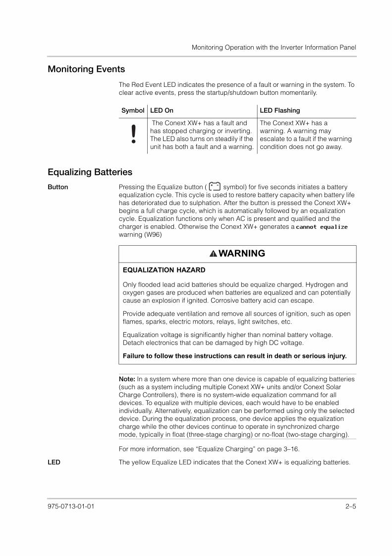
Monitoring Events
The Red Event LED indicates the presence of a fault or warning in the system. To clear active events, press the startup/shutdown button momentarily.
Equalizing Batteries
Button Pressing the Equalize button ( symbol) for five seconds initiates a battery equalization cycle. This cycle is used to restore battery capacity when battery life has deteriorated due to sulphation. After the button is pressed the Conext XW+ begins a full charge cycle, which is automatically followed by an equalization cycle. Equalization functions only when AC is present and qualified and the charger is enabled. Otherwise the Conext XW+ generates a cannot equalize warning (W96)
For more information, see “Equalize Charging” on page 3–16.
LED The yellow Equalize LED indicates that the Conext XW+ is equalizing batteries.
Symbol LED On LED Flashing
The Conext XW+ has a fault and has stopped charging or inverting. The LED also turns on steadily if the unit has both a fault and a warning.
The Conext XW+ has a warning. A warning may escalate to a fault if the warning condition does not go away.
WARNING
EQUALIZATION HAZARD
Only flooded lead acid batteries should be equalize charged. Hydrogen and oxygen gases are produced when batteries are equalized and can potentially cause an explosion if ignited. Corrosive battery acid can escape.
Provide adequate ventilation and remove all sources of ignition, such as open flames, sparks, electric motors, relays, light switches, etc.
Equalization voltage is significantly higher than nominal battery voltage. Detach electronics that can be damaged by high DC voltage.
Failure to follow these instructions can result in death or serious injury.
Note: In a system where more than one device is capable of equalizing batteries (such as a system including multiple Conext XW+ units and/or Conext Solar Charge Controllers), there is no system-wide equalization command for all devices. To equalize with multiple devices, each would have to be enabled individually. Alternatively, equalization can be performed using only the selected device. During the equalization process, one device applies the equalization charge while the other devices continue to operate in synchronized charge mode, typically in float (three-stage charging) or no-float (two-stage charging).
975-0713-01-01 2–5

Monitoring Operation
XW_Europe_Operation.book Page 6 Thursday, July 30, 2015 4:12 PM
Using Startup/Shutdown/Standby Modes
Startup/Shutdown control
When the Conext XW+ is operating, pressing and holding the STARTUP/SHUTDOWN button for five seconds shuts down the unit. To return the unit to its previous operating state, press the STARTUP/SHUTDOWN button again.
While the Conext XW+ is turning off, the other inverter information panel buttons stop working. The shutdown process cannot be cancelled. The Conext XW+ can only be restarted once the display is blank.
Standby mode In Standby mode, the Conext XW+ stops charging, inverting, and allowing AC to pass through to the AC output. However, the unit remains powered and present on the Xanbus network.
To put the Conext XW+ into Standby mode, press and hold the STARTUP/SHUTDOWN button and the Equalize button simultaneously for about five seconds. The display shows . To return the Conext XW+ to operating mode, press the STARTUP/SHUTDOWN button momentarily.
Pressing the STARTUP/SHUTDOWN button momentarily while the Conext XW+ is operating clears active faults and warnings.
Single-unit installations
In a single-unit installation, when the Conext XW+ is shut down using the STARTUP/SHUTDOWN button, Xanbus network power is off. When Xanbus network power is off, network-connected accessories such as the Automatic Generator Start (Conext AGS) and Conext SCP could lose power and stop operating. Conext Solar Charge Controllers continue to operate if Xanbus network power is removed, but they do not continue to communicate with each other. Furthermore, the Conext Combox will not collect harvest data while it is off, even though MPPT is still functioning and collecting data.
If the STARTUP/SHUTDOWN button is pressed and held on a Conext XW+ and a Conext AGS is installed in the system, the unit stops inverting or charging immediately and shuts down completely in 120 seconds. During this time, the display shows . This interval allows the Conext AGS to stop the generator after a cool down period. During the 120 second shutdown time, all network communication is blocked and the unit sends a shutdown command to all other devices in the system. As well, the inverter information panel buttons stop working. The shutdown process cannot be cancelled. The Conext XW+ can only be restarted once the display is blank.
Multiple-unit installations
If the STARTUP/SHUTDOWN power button is pressed and held on a master Conext XW+ (see “Inverter Mode” on the “Multi-Unit Config Menu” on page 3–33) and a Conext AGS is installed in the system, the unit stops inverting or charging immediately and turns off completely in 120 seconds. During this time, the display shows . This interval allows the Conext AGS to stop the generator after a cool down period. During the 120 second shutdown time, the master unit stops network communication and the slave units issue an external sync fault (F69) or a
Symbol LED On LED Flashing
The Conext XW+ has begun equalizing the batteries.
Equalization has been requested but has not begun. The Conext XW+ must complete a charge cycle before applying the equalization charge.
2–6 975-0713-01-01

Monitoring Operation with the Inverter Information Panel
XW_Europe_Operation.book Page 7 Thursday, July 30, 2015 4:12 PM
system configuration fault (F66). As well, the inverter information panel buttons stop working. The shutdown process cannot be cancelled. The Conext XW+ can only be restarted once the display is blank.
In a multiple-unit installation, when a slave Conext XW+ is shut down, other Conext XW+ units continue to supply Xanbus network power and the Conext AGS and Conext SCP continue to operate.
Monitoring Battery Level
When the Conext XW+ is inverting, the row of five LEDs indicates the approximate available SOC (State of Charge) of the batteries connected to the system. This capacity reading is based on battery voltage.
The battery LEDs can retrieve information from various sources depending on the devices installed in the system. SOC information is reported from one of the following devices, listed in order of priority:
1. Conext Battery Monitor (If installed)
2. Conext MPPT Solar Charge Controller (When operating)
3. Conext XW+
When the Conext XW+ is reporting, there are four battery states from empty to full. When the available battery state is empty, no LEDs are lit. The battery is considered empty when its depth of discharge exceeds approximately 50 per cent. When the battery capacity is low, the two leftmost LEDs are lit. When the battery is at medium capacity, the four leftmost LEDs are lit. When the battery capacity is full, all five LEDs are lit. When the Conext Battery Monitor or Conext MPPT Solar Charge Controller devices are reporting, the true SOC will be indicated on the battery level LEDs and all LEDs will be utilized.
Figure 2-3 Battery Level LEDs
975-0713-01-01 2–7

Monitoring Operation
XW_Europe_Operation.book Page 8 Thursday, July 30, 2015 4:12 PM
Reading the Display Screen
The numeric display screen shows the following information about the operational state of the Conext XW+:
• Output power in kilowatts (when the (kW) LED is lit).
• Battery charger current in amps when the (A) charging LED is lit.
• when the Conext XW+ is in Standby mode.
• when the Conext XW+ is in Search mode. See “Using Search Mode” on page 3–8.
• when the startup/shutdown button is pressed and held for five seconds. is displayed briefly before the unit turns off.
• “” appears when the Conext XW+ is in transition between modes, when inverter selection is disabled via the SCP or Conext Combox, or operating in AC pass through mode in a multi-cluster configuration.
• appears momentarily when the Conext XW+ is enabled.
• appears momentarily when the Conext XW+ is disabled.
• 5 minute countdown timer value may appear if there is no other more significant information to display after grid interruption during energy export operation.
Note: The battery LEDs are not a precise indicator of battery level. They are to be considered a general guideline rather than an exact measurement. For greatest accuracy, install the Conext Battery Monitor (Part # 865-1080-01).
2–8 975-0713-01-01

Monitoring Operation with the Xanbus SCP
XW_Europe_Operation.book Page 9 Thursday, July 30, 2015 4:12 PM
Monitoring Operation with the Xanbus SCP
The Xanbus System Control Panel (Conext SCP) provides remote configuration and monitoring capability for the Conext XW+ and all other Xanbus-enabled devices in the network.
You can monitor Conext XW+ operation on the Conext SCP using the:
• System Status screen (see page 2–13)
• Conext XW+ Home screen (see page 2–13)
• Conext XW+ Meters Menu (see page 2–15).
Xanbus System Control Panel Features
Feature Description
1 Event/Warning light indicates a device on the system has a fault or warning condition and requires attention. The light flashes when a warning occurs and turns on steadily when a fault occurs.
2 Enter button confirms selection of a menu item or displays the next screen.
3 Up arrow button scrolls upwards through screen text or increases a selected value.
4 Down arrow button scrolls downwards through screen text or decreases a selected value.
5 Exit button cancels selection of a menu item or displays the previous screen.
6 Display shows menus, settings, and system information.
7 Standby button disables inverting and charging on all Conext XW+s in the system when pressed for one to two seconds. To enable inverting and charging, press the Standby button again.
StandbyEvent/Warning
Conext SCP
1
2 3 4 5
7
6
975-0713-01-01 2–9
Monitoring Operation
XW_Europe_Operation.book Page 10 Thursday, July 30, 2015 4:12 PM
Using the Standby Button
The Standby button has two functions. The Standby button can disable inverting and charging for the Conext XW+ units in the system or when pressed simultaneously with the Exit button, can put the entire system into Standby mode.
Pressing the Standby button produces the same result as disabling Invert and AC Charge in the System Settings menu. Pressing the Standby button momentarily affects only Conext XW+ units; it does not affect Conext Solar Charge Controller operation. After disabling inverting and charging with the Standby button, the system continues to pass AC power through to the loads, and “” is displayed on the inverter information panel.
Pressing the Exit and Standby buttons at the same time puts the entire Conext power system (including Conext Solar Charge Controllers) into Standby mode. In Standby mode, the Conext XW+ units stop passing AC power through to the loads, and is displayed on inverter information panel.
If a Conext AGS is installed and a generator is running, the system commands the generator through a cool down and shut down cycle. This operation cannot be interrupted and may take up to 120 seconds.
Xanbus System Control Panel Navigation
This section describes the different types of screens and menus on the Conext SCP that are useful for monitoring and controlling Conext XW+ operation.
Viewing the Xanbus SCP Home Screens
The top level screens on the Conext SCP are the startup screen, the System Status screen and the device Home screen. Whenever power is applied the startup screen appears, followed by the System Status screen. Press the up or down key to view the device Home screen for any system connected Xanbus devices. See Figure 2-4.
2–10 975-0713-01-01

Monitoring Operation with the Xanbus SCP
XW_Europe_Operation.book Page 11 Thursday, July 30, 2015 4:12 PM
System Status Screen The System Status screen appears after the startup screen. It displays aggregated status information for the entire power system. For example, a single system might have three Xanbus network-connected Conext XW+ Inverter/Chargers, two Conext Solar Charge Controllers, one Conext AGS module, and one Conext SCP connected to a single battery bank, a single generator, and a common utility grid.
The System Status screen features a Menu arrow pointing to the Enter button. Pressing Enter takes you to the Select Device menu. For more information, see “Reading the System Status Screen” on page 2–13.
Figure 2-4 Xanbus System Control Panel Top Level Screens
System Status Select Device
XW+ 8548 : Home
Device 2 : Home
Device 3 : Home
Device n : Home
Appears for a few seconds after the system starts up or when the system has been reset.
Press Enter to view Select Device menu.
Select device from list and press Enter to view Device Setup menu.
Press Enter from a Device Home screen to view the Device Setup menu.
The number of Home screens depends on the number of Conext Xanbus-enabled devices installed in the system.
Startup Screen
System Status Screen
Conext XW+ Home Screen
Device 2 Home Screen
Device 3 Home Screen
Device n Home Screen
Select Device Screen
Note: If you are uncertain as to which Conext SCP screen or menu you are viewing, you can return to the starting point—the System Status screen—by pressing Exit repeatedly until the screens stop changing.
975-0713-01-01 2–11

Monitoring Operation
XW_Europe_Operation.book Page 12 Thursday, July 30, 2015 4:12 PM
Conext XW+ Home Screen The Conext XW+ Home screen is the first of the Device Home screens. Each Conext XW+ installed in the system has its own Home screen.
The Conext XW+ Home screen displays status information for the Conext XW+. The screen appearance varies with the status of the Conext XW+ (standby, inverting, etc.) For more information, see “Reading the Conext XW+ Home Screen” on page 2–13.
To display the Conext XW+ Home screen:
• While viewing the System Status screen, press the down arrow key.
Viewing Other Screens
This section describes the next level of screens and menus on the Xanbus SCP.
Select Device Menu The Select Device menu displays a list of Xanbus-enabled devices in the system, including the Conext XW+ and the Conext SCP. From this menu you can access the Setup menus for each device in the system.
The Select Device menu also contains the Clock menu (where the time and date are set) and the System Settings menu (where system-level settings can be configured). These menus and the Conext SCP menu are available from the Select Device menu, regardless of the number of Xanbus-enabled devices installed.
To display the Select Device menu:
• While viewing the System Status screen, press Enter.
Device Setup Menus Device Setup menus display status information (on the Meters screen) and changeable settings. Changeable settings are identified by the square brackets [ ] around values in the right-hand column.
To display the Setup menu for a device:
• Highlight the device name on the Select Device menu and press Enter.Alternatively, from the device Home screen, press Enter.
Figure 2-5 Selecting a Device Setup Menu
Select Device
XW+ 8548
XW+ 8548 00: SetupMeters
[Enabled][Disabled][Disabled][Enabled]
[Bulk][Disabled]
[Operating]
Select device from list, and then press Enter to view Device Setup menu
Select Device menuConext XW+ Setup menu
2–12 975-0713-01-01

Monitoring Operation with the Xanbus SCP
XW_Europe_Operation.book Page 13 Thursday, July 30, 2015 4:12 PM
Reading the System Status Screen
The System Status screen displays:
• Qualified AC source (if applicable) and total power to and from the source.
• Battery voltage and capacity level.
• Net battery input or output current.
• Total inverter loading.
• Time and date.
Reading the Conext XW+ Home Screen
The Conext XW+ Home screen displays real-time operating data specific to the Conext XW+. The Conext XW+ status changes according to the states described in Table 2-1 on page 2–14.
To view the Conext XW+ Home screen:
• On the system Home screen, press the down arrow button until the Conext XW+ Home screen appears.
Press the down arrow button from the Conext XW+ Home screen to display the Home screens for other units and other Xanbus-enabled devices in the system.
Figure 2-6 System Status Screen
System Status
menu
20.4A 53.9V
115V 3202W
E--F1235W
9:18AM Mar 10
Line 2: Battery level meterLine 3: Power supplied to loadsLine 4: AC input source and line-to-neutral voltage. The bottom left corner displays AC1 or AC2 depending on the active input source. When selling to the grid, the power displayed is positive. When charging, the power displayed is negative.
Menu arrow indicates the Enter button. Pressing Enter displays the Select Device menu.
Line 1: Battery voltage and input/output current (positive when charging, negative when inverting)
Figure 2-7 Conext XW+ Home Screen
setup system
XW+ 8548 00:HomeInvert
-26.4A 51.9V1250W
0.0V 0W
Top Line: Device name and numberLine 1: Inverter/charger statusLine 2: Battery current (in + or out –) and voltage
Line 3: Power supplied to loadsLine 4: AC in status
The setup arrow indicates the Enter button. Press to display the inverter/charger setup menu.
The system arrow indicates the Exit button. Press to display the System Home screen.
975-0713-01-01 2–13

Monitoring Operation
XW_Europe_Operation.book Page 14 Thursday, July 30, 2015 4:12 PM
Table 2-1 Conext XW+ Home Screen States
Conext XW+ Status Displayed When...
Invert The Conext XW+ is supplying power to loads on AC OUT by inverting power from the batteries. AC input from the utility (AC1) or generator (AC2) is absent or out of nominal range.
Qualifying AC The Conext XW+ is determining if AC input on AC1 or AC2 is within a usable voltage and frequency range. Qualifying AC is also displayed when the Conext XW+ is awaiting application of AC power or a command to enable invert mode.
Charging The Conext XW+ is charging the batteries from qualified AC input from the utility grid (AC1) or a generator (AC2). The charge state is in transition to either bulk, absorption, float, or equalize. AC input is also passed through to the load while charging.
Bulk The Conext XW+ is bulk charging the batteries from qualified AC input from the utility grid (AC1) or a generator (AC2). AC input is also passed through to the load while bulk charging.
Absorption The Conext XW+ is absorption charging the batteries from qualified AC input from the utility grid (AC1) or a generator (AC2). AC input is also passed through to the load while absorption charging.
ABS Finish The Conext XW+ has completed the absorption stage and is waiting for other Conext XW+ units in the system to complete absorption. This status can occur only when there is another Conext XW+ also charging the battery.
Float The Conext XW+ is float charging the batteries from qualified AC input from the utility grid (AC1) or a generator (AC2). The Conext XW+ is set for three-stage charging. AC input is also passed through to the load while float charging.
CHG Finish The Conext XW+ has completed charging or the charge cycle has been interrupted and is transitioning to the next state. This stage lasts about one minute, while the battery is allowed to settle and battery voltage to drop back to normal. The delay keeps the Conext XW+ from unnecessarily transitioning to grid support (if enabled) due to the high battery voltage after a charge cycle.
Fault The Conext XW+ has an active fault. The Fault/Warning light on the Conext SCP is on.
Gen Support There is AC input from the generator on AC2, and the Conext XW+ is supporting the generator by supplying additional power to the loads attached to AC Out.
The Conext XW+ supports the generator (or other power source connected to the generator [default AC2] input) when the AC load current drawn from the generator exceeds the GenSup Amps setting for 1 to 2 seconds.
The Conext XW+ uses stored battery energy to load share with the generator until the total AC load current (generator plus Conext XW+ output) drops by 2 amps plus 10 per cent of the GenSup Amps setting for 0.5 seconds.
For example, if GenSup Amps is set to 10 amps, the Conext XW+ starts to support when the load exceeds 10 amps for 2 seconds and stops when it drops more than 3 amps below the GenSup Amps setting, or 7 amps (2 amps plus 10 per cent of 10 amps = 3 amps).
The system can enter this state if the battery voltage is above Low Batt Cut Out +2V and generator support is enabled. See “Generator Support Settings” on page 3–29.
2–14 975-0713-01-01

Monitoring Operation with the Xanbus SCP
XW_Europe_Operation.book Page 15 Thursday, July 30, 2015 4:12 PM
Reading the Meters Screen
The Meters screen displays total system power production, grid voltage and current status, and load voltage and current status.
To view the Meters screen:
• On the Conext XW+ setup menu highlight Meters, and then press Enter.
Grid Support There is AC input from the utility grid on AC1, however the priority for the Conext XW+ is to supply energy converted from external DC sources to the critical loads on AC Out.
The Conext XW+ enters this state only when Grid Support is set to ON and battery voltage is above the Grid Supp Volts setting. See “Grid Support Settings” on page 3–22.
APF mode APF (Active Power Frequency) mode is active. APF mode automatically injects or reduces active power to the grid based on a predefined frequency to power relationship. APF settings are only available through the Conext Configuration Tool. For further details, see the Conext Configuration Tool Owner’s Guide.
Load Shaving The Conext XW+ supports the utility grid when there is AC input on AC1 and the current required to power the loads rises above the Load Shave Amps setting between the Load Shave Start and Load Shave Stop times set on the Grid Support menu.
When load shaving, the Conext XW+ uses stored battery energy to reduce the peak load on the AC1 input by providing the difference between the actual load current and the Load Shave Amps setting. The Conext XW+ enters this state only when Grid Support is enabled, the load shave time window is valid and the load draw exceeds the Load Shave Amps setting. The battery voltage must also be between + 2 VDC and the Grid Support Volts setting. See “Grid Support Settings” on page 3–22.
Search Search mode is enabled and the Conext XW+ is standing by, waiting to begin inverting. See “Using Search Mode” on page 3–8.
SellToGrid The Conext XW+ is grid-tied and is exporting energy to the utility grid on AC1. Both Grid Support and Sell must be enabled in order to sell power back to the utility. See Table 3-1, “Conext XW+ Setup menu” on page 3–2 and “Grid Support Settings” on page 3–22. All configurations must comply with local and national electrical codes.
Standby The unit has been placed in standby mode using the Mode setting on the Conext SCP Setup menu, the Standby button on the Conext SCP, or the Standby key press (STARTUP/SHUTDOWN and Equalization) on the inverter information panel.
Passthru The AC connected to the AC1 or AC2 input is passing directly through the Conext XW+ to the loads attached to AC Out. The batteries are not being charged in this state.
Equalize Equalization has been turned on and the Conext XW+ is equalizing the batteries after completing a full charge cycle.
Table 2-1 Conext XW+ Home Screen States
Conext XW+ Status Displayed When...
975-0713-01-01 2–15

Monitoring Operation
XW_Europe_Operation.book Page 16 Thursday, July 30, 2015 4:12 PM
Figure 2-8 Viewing the Meters Screen
Table 2-2 Meters Screen
Screen Item Description
AC1 AC input power connected to the Conext XW+ AC1 terminals, in Volt-Amps and Watts. AC1 is assumed to be connected to the utility grid, but it can be connected to any other AC source.
AC1 In AC input voltage and current connected to the Conext XW+ AC1 terminals. This input voltage display might drift slightly before the inverter has synchronized to the grid.
AC1 Freq AC frequency connected to the Conext XW+ AC1 terminals.
AC2 AC input power connected to the Conext XW+ AC2 terminals, in Volt-Amps and Watts. AC2 is assumed to be connected to a generator, but it can be connected to any other AC source.
AC2 In AC input voltage and current supplied to the inverter/charger from the AC2 input. This meter indicates the inverter/charger is drawing power from the generator to charge the battery or power the AC loads.
AC2 Freq AC frequency connected to the Conext XW+ AC2 terminals.
Load Power Power consumed by the AC loads attached to AC OUT, in Volt-Amps and Watts.
ACLoad AC voltage and current supplied to the AC loads.
Load Freq AC frequency supplied to the AC loads on AC OUT.
State Operating state of the Conext XW+. For more information, see Table 2-1 on page 2–14.
DC Charging current and battery voltage.
Batt Temp Battery temperature as read by the BTS, connected to the Conext XW+. If the BTS is connected to a different device on the Xanbus network, please see the Meters screen for that device for temperature data. All Xanbus devices on the Xanbus network will share temperature data for temperature compensated charging. However, the temperature is only displayed on the meters screen for the device with the BTS installed. The BTS which is monitoring the device displaying the highest temperature will take priority. If the BTS is not installed, it shows NotAvailable.
XW+ 8548 00: Meters2300VA 1650W10.1A 230V
50Hz0VA 0W
0.0A 0V0Hz
2300VA 1650W10.1A 230V
50HzFloat
3.7A 57.4V20 ° C
XW+ 8548 00: SetupMeters
[Enabled][Disabled][Disabled][Enabled]
[Bulk][Disabled]
[Operating]
2–16 975-0713-01-01

XW_Europe_Operation.book Page 1 Thursday, July 30, 2015 4:12 PM
3 Configuration
Chapter 3, “Configuration” explains how to navigate through the Xanbus System Control Panel menus and configure the Conext XW+ Inverter/Charger.
Topics in this chapter include:• “Using the Xanbus System Control
Panel” on page 3–2• “Using the Setup Menus” on page 3–4• “Inverter Settings Menu” on page 3–7• “Charger Settings Menu” on page 3–9• “AC Input Settings” on page 3–21• “Grid Support Settings” on page 3–22• “Generator Support Settings” on
page 3–29• “Auxiliary Output Settings” on page 3–
31• “Multi-Unit Config Menu” on page 3–33• “Connections Menu” on page 3–38• “Copying Settings From Another Unit”
on page 3–39• “Restoring the Conext XW+ to Factory
Default Settings” on page 3–40• “Using the Advanced Features” on
page 3–41

Configuration
XW_Europe_Operation.book Page 2 Thursday, July 30, 2015 4:12 PM
Using the Xanbus System Control Panel
The Conext XW+ is configured using the Conext SCP (Xanbus System Control Panel). The Conext SCP provides access to settings relating to AC input and output, battery charging, and grid-tie operation.
Conext XW+ Setup Menu
The Conext XW+ Setup menu is accessible from the System Home screen and the Conext XW+ Home screen.
To navigate to the Conext XW+ Setup menu:
1. From the system Home screen, press Enter to view the Select Device menu. Or from the Conext XW+ Home screen, press Enter. The Conext XW+ Setup menu appears. Go to step 2.
2. Highlight the Conext XW+ device name, then press Enter.
Figure 3-1 Conext XW+ Setup menu
Table 3-1 Conext XW+ Setup menu
Menu Item Description
Meters Displays the Meters screen.
Inverter Enables or disables the inverter.
Search Mode Turns Search Mode on and off. See “Using Search Mode” on page 3–8.
XW+ 8548 00: SetupMeters
[Enabled][Disabled][Disabled][Enabled]
[None][Disabled]
[Operating]Note: The Conext SCP only displays four lines of the Setup menu at once. To view additional settings, press the Down arrow button.
3–2 975-0713-01-01

Using the Xanbus System Control Panel
XW_Europe_Operation.book Page 3 Thursday, July 30, 2015 4:12 PM
Setting the Time and Date
Conext XW+ advanced features such as peak load shaving, charger block, and time-stamped events (faults, warnings, and logged historical data) require that the system be set to the correct time. The Conext SCP has an internal clock that controls the time for the Xanbus-enabled devices in the system. You can set the time, time format, and date on the Clock menu. The Clock menu is accessible on the Select Device menu.
For more information, see “Setting the Time” and “Setting the Date” in the Xanbus System Control Panel Owner’s Guide.
Grid Support Enables or disables grid-interactive Conext XW+ features, such as grid support and grid sell mode. See “Grid Support Settings” on page 3–22. To allow grid support to function after battery charging has completed, it is recommended to set the Charge Cycle to 2-Stage. The MPPT controllers must still be set to 3-stage. See “Charger Settings Menu” on page 3–9. When using load shave, turning ON Sell and setting Sell Amps to 0.0 is a way to make the net power flow to the grid zero. If sell is not enabled, there will be a net purchase of as much as 2.0 - 3.0 kWh per day due to the current control loop not allowing any outgoing current. If you wish to further reduce grid draw using this function, enable sell mode even if you do not wish to export power and set Max Sell Amps to a value of 0.
Charger Enables or disables the charger.
Force Chg Manually changes the charge stage to either Bulk or Float (when 3-Stage cycle is selected) or Bulk or NoFloat (when 2-Stage cycle is selected).
Equalize Enables or disables battery equalization. This option is only available if the battery type is set to Flooded or is set to Custom with Equalize Support enabled.
Mode Selects the Conext XW+ operating mode: Operating or Standby. The red Standby button on the Xanbus SCP has similar functionality (see “Xanbus System Control Panel Features” on page 2–9).
Clear Faults/Warnings
Clears any active faults or warnings. If the fault or warning condition is still present, the fault or warning message may reappear.
View Device Info Displays the Device Info screen where you can view the warning, fault, and event logs.
Basic Settings Select to display and/or adjust the basic Conext XW+ settings. See “Using the Setup Menus” on page 3–4.
Table 3-1 Conext XW+ Setup menu
Menu Item Description
Note: Network time on the ComBox overrides time configured on any individual device in the network-enabled power system using network time protocol (NTP).
If your device is not compatible with NTP, Conext XW+ features such as peak load shaving and charger block may not work correctly, and charge controller daily power production values may reset at an unexpected time. If your device is working incorrectly, configure the ComBox to use the local time and date. See the ComBox Owner’s Guide, Document Part # 975-0679-01-01 for more information.
975-0713-01-01 3–3
Configuration
XW_Europe_Operation.book Page 4 Thursday, July 30, 2015 4:12 PM
Using the Setup MenusBasic menu The Conext XW+ configuration settings can be viewed in Basic and Advanced
formats (see Figure 3-3, “Basic and Advanced Settings” on page 3–6). The basic settings include configuration items you may have to adjust routinely, or as part of initial setup.
Advanced menu The advanced settings option gives you access to the full range of Conext XW+ settings, including everything displayed on the basic menu. As a safeguard against unintended advanced configuration, the Conext SCP displays the basic settings by default. To view the advanced settings, you must perform a special keypress.
To select the Advanced settings:
1. On the Select Device menu, select a Conext XW+.
2. Press and release Enter + up arrow + down arrow at the same time.
The Conext XW+ Advanced settings include menus for configuring:
• Inverter settings (see page 3–7)
• Charger settings (see page 3–9)
• AC transfer limit settings (see page 3–21)
• Grid Support and Peak Load Shaving settings (see page 3–22)
• Generator Support settings (see page 3–29)
• Auxiliary output settings (see page 3–31).
• Multi-Unit Operation, including customizing the default model name of the inverter/charger and setting its network device number. Setting the device number is important when multiple Conext XW+ units are on the Conext
WARNING
ADVANCED CONFIGURATION HAZARD
Advanced menu settings should be used by qualified personnel only.
Three phase operation should be configured by qualified personnel only.
Consult with the local utility before enabling Conext XW+ sell mode or grid support functions.
Do not change these settings unless you are under the supervision and direction of qualified personnel.
Failure to follow these instructions can result in death or serious injury.
Notes:
• This keypress enables the Advanced settings for every device in the system.
• After performing the keypress, “Advanced Settings” appears at the top of the Setup menu. When the keypress is performed again, the Setup menu displays “Basic Settings” as the last item on the menu.
3–4 975-0713-01-01

Using the Setup Menus
XW_Europe_Operation.book Page 5 Thursday, July 30, 2015 4:12 PM
Xanbus network and sharing connections such as AC loads, utility grid, and generator. The device number is also used when configuring paralleled Conext XW+ units for master-slave operation (see page 3–7).
In the advanced settings you can also copy another unit’s settings using the Copy from command.
To view the Advanced or Basic settings:
• From the Setup menu, with Basic Settings or Advanced Settings highlighted, press Enter. See Figure 3-2.
To select and change a configurable setting:
1. On the desired configuration menu, press the up arrow or down arrow button to highlight the setting you want to change.
2. Press Enter to highlight the current value of the setting.
3. Press the up arrow or the down arrow button to change the value. Hold down the button to scroll through a large range of values quickly.
The previously set value appears with an asterisk (*) beside it.
4. Press Enter to select the value.
5. If you have another setting to change, return to step 1. Or if you have no more settings to change, press Exit until the Conext SCP displays the desired screen or menu.
Figure 3-2 Selecting Advanced Settings
XW+ 8548 00: AdvInverter Settings
[XW+ 8548 01]
XW+ 8548 00: SetupAdvanced Settings
[Enabled][Disabled][Disabled][Enabled]
[None][Disabled]
[Operating]
Note: If you have no more settings to change, it is recommended to leave the Setup menu in the basic settings format to help prevent unintended configuration. If the Setup menu displays Advanced Settings, press Enter + up arrow + down arrow at the same time. The Setup menu should then display Basic Settings as the last item on the menu.
975-0713-01-01 3–5

Configuration
XW_Europe_Operation.book Page 6 Thursday, July 30, 2015 4:12 PM
Figure 3-3 Basic and Advanced Settings
XW+ 8548 00:AC
XW+ 8548 00:Inv
XW+ 8548 00: Multi
XW+ 8548 00:Gen
XW+ 8548 00: Aux
XW+ 8548 00:Grid
XW+ 8548 00:Chg
Custom Settings
XW+ 8548 00: Adv
Connections
[46V][10s][2.0V][70V][50W][2s]
[Enabled][64.0V][57.6V][57.6V][54.0V]
[108mV/C]
[Flooded]
[440Ah][100%]
[2-Stage][Warm][50V]
[180min][12:00AM][12:00AM]
[AC1][56A][202V][260V][45Hz][55Hz][56A][202V][264V][45Hz][55Hz]
[53V][Disabled]
[27A][Disabled]
[44A][12:00AM][12:00AM][12:00AM][12:00AM]
[ManualOff][ActHi]
[LowBattV][44V][1sec][48V][1sec]
[XW+8548][00]
[1PhMaster]
XW+ 8548 00:Adv Features
[Disabled][Disabled][Disabled][Enabled][Disabled][Enabled][Disabled]
[HouseBatt1][ACLoad1][Grid1][Gen1]
[Disabled][44A]
[XW+ 8548 01]
LithiumIon
[EXT_BMS][14.4V][140A][14.4V][140A][14.4V][140A][150%][10s]
XW+ 8548 00:BasicBatt Type [Flooded]
[440Ah][100%]
[2-Stage][50V][AC1][60A][60A][54V][44V]
Advanced Settings
Basic Settings
Note: The Xanbus SCP displays only four lines of each configuration menu at one time. To view additional settings, press the down arrow button.
Custom Settings is displayed only when Custom is selected as the Batt Type.
Eqlz Voltage is displayed only when Eqlz Support is Enabled.
LithiumIon is displayed only when Custom is selected as the Batt Type.
Trigger and Clear settings are displayed only when Automatic is selected under Manual Aux.
3–6 975-0713-01-01

Inverter Settings Menu
XW_Europe_Operation.book Page 7 Thursday, July 30, 2015 4:12 PM
Inverter Settings Menu
The Inverter Settings Menu contains settings that control when the Conext XW+ turns on and off while inverting.
For default settings, see “Inverter Menu” on page B–3.
Table 3-2 Inverter Settings Menu
Item Description
Low Batt Cut Out
Low Batt Cut Out controls when the inverter turns off due to a low battery voltage condition. The inverter will turn off only after this level has been reached for the period of time set for LBCO Delay. This setting is not temperature compensated.
LBCO Delay
LBCO Delay controls how long the inverter is allowed to operate at or below the Low Batt Cut Out level before turning off due to a low battery voltage condition. The inverter will stop producing AC output only after the Low Batt Cut Out setting has been reached for this uninterrupted period of time.
Once the inverter has shut off, the battery voltage must rise 4 volts above the Low Batt Cut Out setting for inverter operation to resume.
High Batt Cut Out
High Batt Cut Out sets the maximum battery voltage at which the inverter will operate. If the battery voltage exceeds this limit for more than 1 minute, the inverter displays a fault message (F49) and shuts down. The inverter will not support AC loads when in this condition. If a qualified AC source is present, the unit passes AC through to the loads. The inverter automatically restarts when the voltage drops to 6 volts below the High Batt Cut Out setting. If battery voltage continues to rise after shutdown, an external charger may still be charging the batteries. The Conext XW+ cannot control how external chargers operate.
Search Watts
Search Watts sets the inverter’s search sensitivity when Search mode is enabled. When a load larger than this setting is present on AC OUT, the inverter starts producing AC output from battery power. Enabling Search mode from the Setup Menu (see page 3–2) can minimize power draw from the battery during periods of low demand from loads. Also see “Using Search Mode” on page 3–8.
Search Delay
Search Delay sets the time between search pulses. When searching for loads, the Conext XW+ sends out search pulses on AC OUT to determine the presence of a load above Search Watts. Conext XW+ power draw while in search mode decreases when Search Delay is increased, but the Conext XW+ response time to active loads is slower.
975-0713-01-01 3–7

Configuration
XW_Europe_Operation.book Page 8 Thursday, July 30, 2015 4:12 PM
Using the Low Battery Cut Out and LBCO Delay Settings
The Low Batt Cut Out setting is the lowest battery voltage level acceptable for use by the inverter. When the batteries discharge to the Low Batt Cut Out setting, and are held at or below this level for the LBCO Delay time, the inverter output shuts down and connects any available AC source (AC1 or AC2) to the charger to bring the battery level back above the Low Batt Cut Out setting. After shutdown, the inverter does not support loads on AC OUT, and AC loads must be powered by either a generator (AC2) or grid power (AC1). If the battery voltage stays below the LBCO voltage for more than 24 hours, the Conext XW+ shuts down.
• If using the Conext Automatic Generator Start system, it is recommended to set the Conext AGS voltage trigger setting higher than the Conext XW+ Low Batt Cut Out voltage.
• Although not recommended, if using the Conext Automatic Generator Start system with the start trigger set to the same voltage as the LBCO voltage, do not set the LBCO Delay for less than the amount of time it takes the generator to start and connect.
Otherwise – in both of the scenarios above – inverter output turns off before the generator automatically starts, causing the battery voltage to recover slightly. This may then stop the Conext AGS from starting the generator or result in the Conext XW+ cycling on and off multiple times before the generator automatically starts.
Using Search Mode
Why use Search mode?
Search mode allows the inverter to selectively power only items that draw more than a certain amount of power, which can result in energy savings. The Conext XW+ has a no-load power draw of about 28 watts. Enabling Search mode reduces this power draw to less than 8 watts. Search mode operates differently in single-unit and multi-unit installations.
Single units When a single Conext XW+ has search mode enabled, the inverter sends electrical search pulses through its AC output. These search pulses look for connected AC loads. The delay between search pulses is set using the Search Delay setting. After a load larger than the Search Watts setting is detected, the inverter starts producing AC output.
WARNING
ADVANCED CONFIGURATION HAZARD
Advanced menu settings should be used by qualified personnel only.
Three phase operation should be configured by qualified personnel only.
Consult with the local utility before enabling Conext XW+ sell mode or grid support functions.
Do not change these settings unless you are under the supervision and direction of qualified personnel.
Failure to follow these instructions can result in death or serious injury.
3–8 975-0713-01-01

Charger Settings Menu
XW_Europe_Operation.book Page 9 Thursday, July 30, 2015 4:12 PM
Multiple units To use search mode in multiple unit installations with paralleled Conext XW+ units, the master unit must have search mode disabled. Slave units must have search mode enabled.
When search mode is disabled on the master unit and enabled on slave units, only the master Conext XW+ operates, and the slave units start to support the load only when the load exceeds approximately 60 per cent of the rated output power of the master unit. In a three-unit system, the third slave unit starts to support the load if the load on the master is above 60 per cent of its rated power for about 3 to 5 seconds. When the load drops below 20 per cent of the master’s rated output power, the slave units stop producing AC output in reverse order, which means that the last slave unit to start is the first to stop.
When to set up Search mode
The Search mode feature is only valuable if the inverter can spend a fair amount of time “sleeping” each day. Therefore, if Search mode is to be used it must be adjusted properly. The initial adjustment should be made so that the Conext XW+ comes on only when needed.
Certain types of loads can cause search mode to work improperly. These types of loads are described on page 4–2 of the Troubleshooting chapter. If these kinds of loads are in the system, follow the suggestions given to resolve the problem.
If the problem loads cannot be resolved, there are two workaround solutions:
1. Disable search mode from the main Conext XW+ Setup menu, causing the inverter to remain at full output voltage.
2. Use a search friendly companion load whose only purpose is to be switched on to wake up the inverter to power the load that is unable to bring the inverter out of search mode.
Charger Settings Menu
The Charger Settings menu provides options for configuring the Conext XW+ to operate from your battery bank.
Notes:
• Search mode, by function, cannot work with clocks and timers or devices that need power 24 hours a day. Examples of devices with timers include video recorders, coffee makers with brew timers, refrigerators, and freezers with defrost timers. Examples of devices that need power 24 hours a day include telephone answering machines, alarm systems, motion detection lights, and some thermostats.
• When the inverter is searching the output for loads, lights that have a wattage lower than this setting may flash momentarily.
975-0713-01-01 3–9

Configuration
XW_Europe_Operation.book Page 10 Thursday, July 30, 2015 4:12 PM
For default settings, see “Charger Menu” on page B–3.
Table 3-3 Charger Settings Menu
Item Description
Batt Type Sets the system battery chemistry and type: Flooded (default), AGM, Gel, LithiumIon, and Custom.
Selecting Custom displays the Custom Settings item, which allows you to adjust the settings for each charging stage.
Custom Settings
Displays the Custom Battery Settings menu, where you can adjust settings specific to your battery type and installation. It is displayed if Custom is selected as the Batt Type. Further custom settings for Lithium Ion batteries appear if Lithium Ion is selected as the Batt Type.
Batt Capacity Selects the system battery capacity in Ah (amp hours). Setting the Batt Capacity to 0 resets the charging current to its default values. Zero Ah battery capacity implies there is no absorption exit current criteria and absorption only exits when the absorption timer (default 3 hours, range 1 minute-8 hours) expires.
Max Chg Rate Sets the percentage of the maximum DC output current that is available to the charger. The maximum DC output current for different models is:
• Conext XW+ 7048 E—110 ADC
• Conext XW+ 8548 E—140 ADC
If multiple Conext XW+ Inverter/Chargers are charging the same battery bank, set each inverter's Max Chg Rate to 1/n of the desired charge rate (where n is the number of inverter/chargers).
Note: Always refer to the battery manufacturer’s specifications before setting the Max Chg Rate. Do not set the Max Chg Rate above these specifications.
Charge Cycle Sets the charging method: 3-Stage (bulk, absorption, float) or 2-Stage (bulk, absorption, no float).
Default Batt Temp
Selects the battery temperature charging compensation if a battery temperature sensor is not installed. In the absence of a battery temperature sensor, the charger uses one of three settings: Cool (5 °C), Warm (25 °C), or Hot (40 °C).
ReCharge Volts
When charger is set for 2-stage operation, sets the battery voltage level at which a new charge cycle begins. ReCharge Volts is automatically temperature compensated to be consistent with the charge voltage (also temperature compensated).
Absorb Time Sets the maximum time spent in the absorption stage, before transitioning to float or no float.
Chg Block Start
Sets the time to halt charging on AC1 (Grid). The AC2 (Gen) port is unaffected by the Conext XW+ block settings. The charger block start and stop settings allow you to select when the charger stops charging on AC1. To disable the charger block function, set Chg Block Start and Chg Block Stop to the same time. See “Grid Support” on page 3–24.
Chg Block Stop
Sets the time that charging on AC1 can resume. At the Chg Block Stop time, charging on AC1 is enabled again.
3–10 975-0713-01-01

Charger Settings Menu
XW_Europe_Operation.book Page 11 Thursday, July 30, 2015 4:12 PM
Battery Charger Functions
Whenever AC power is present, the unit can operate as a battery charger. Different battery types and chemistries require different charging voltage levels. Not charging batteries at the required levels can shorten battery life or damage the batteries. The Conext XW+ is configured at the factory to work with the battery types recommended for inverter applications. If the default settings do not work for your specific installation, adjust the charge stage settings (as recommended by the battery manufacturer) on the Custom Battery Settings menu (see page 3–19).
Multi-Stage Charging Process
The charging cycle is a multi-stage process. Whenever qualified AC power is present at the AC1 or AC2 input, power runs through to the connected load and begins charging the batteries in parallel.
Note: This information is provided for guidance only. Variations in battery chemistry and site-specific environmental considerations mean that you should consult your system designer or battery manufacturer for specific recommendations for appropriate battery voltage and current settings.
Figure 3-4 Three-Stage Battery Charging Cycle
Time
Time
Absorption Voltage
Float Voltage
Max Absorb Time - Default 3 hrs(adjustable 1 min - 8 hrs)
BoostTimer
1hr fixed
Absorption Exit CurrentThreshold = 2% of
programmed AH capacity
3-Stage Charge
Custom Charge
Float StageAbsorption StageBulk Stage
(Boost Stage)
BatteryCurrent
Max ChargeRate
BatteryVoltage
975-0713-01-01 3–11

Configuration
XW_Europe_Operation.book Page 12 Thursday, July 30, 2015 4:12 PM
Bulk Stage Bulk charge is the first stage in the charging process and provides the batteries with a controlled, constant current. Once the battery voltage rises to the bulk voltage threshold, the charger switches to the absorption stage.
Absorption Stage During the absorption stage, the Conext XW+ begins operating in constant voltage mode and the DC charge current falls gradually as energy is returned to the battery. For the first 60 minutes of the absorption stage, the Conext XW+ regulates the battery voltage at the Bulk Voltage setting. The voltage limit used for the remaining time in this stage is the Absorption Voltage setting. By default, the bulk and absorption voltage settings are the same for each battery type. The voltage limit settings for bulk and absorption can be adjusted independently if the battery type is set to Custom. The Conext XW+ transitions to the float stage if either one of the following two conditions are met:
1. The charge current allowed by the batteries falls below the exit current threshold, which is equal to 2% of the programmed battery capacity (for a 500 Ah battery bank, this would be 10 A), for three minutes.
2. The Conext XW+ has been in absorption for the programmed maximum absorption time limit. The default is 3 hours, but the time limit is programmable from 1 minute to 8 hours.
Notes:
When the charge cycle is interrupted, the charger will restart charging at the beginning of the multi-stage algorithm.
Exit Current Threshold can be effectively disabled by programming the amp-hour capacity to 0. In this case, absorption will only exit once the Max Absorption timer expires.
Charge current during equalize state (optional state not shown here) is normally limited to 10% of the programmed amp-hour capacity setting. If this setting is programmed to 0 Ah, the charge current during equalize is instead limited to whatever is programmed for the maximum current limit of the unit (the default current limit in equalize mode is 60 A).
Synchronized charge states are active when more than one charging device (Conext XW+ or Conext Solar Charge Controller) is connected in the system via the Xanbus network.
• The first Conext XW+ or Conext Solar Charge Controller to enter bulk, causes the other chargers to enter bulk.
• The first Conext XW+ to enter absorption causes the other chargers to enter absorption.
• The last Conext XW+ ready to exit absorption triggers the rest to exit absorption and exit charge. The Conext XW+ will not wait for any connected Conext Solar Charge Controllers to transition to absorption or float.
3–12 975-0713-01-01

Charger Settings Menu
XW_Europe_Operation.book Page 13 Thursday, July 30, 2015 4:12 PM
Boost Charging Boost charging allows for better utilization of flooded lead acid batteries under moderate cycling in off-grid or grid support applications. Boost charging encourages a short duration charging voltage—above the gassing voltage—at the beginning of the absorption charge state. Testing has shown that boost charging improves battery performance by providing a regular mixing of the liquid electrolyte. Boost charging specifically discourages capacity robbing acid stratification and plate sulfation.
Boost mode charging can be enabled by selecting the Custom battery type and by setting the bulk voltage higher than the absorption voltage. The multi-stage charge algorithm then attempts to use the higher for the first hour of the absorption stage, unless it is interrupted by the max absorption timer or exit current threshold.
• Boost charging encourages gassing of flooded lead acid batteries.
• Boost charging is NOT recommended for AGM, GEL or any other electrolyte-limited and/or valve-regulated sealed battery application.
• Boost charging may result in higher than normal water consumption. However, the benefits of boost charging are likely to be greater than the extra watering effort. Check battery water levels at least once per month.
Boost charging has maximum benefit when used on batteries that experience moderate cycling. An unoccupied cottage, for example, where batteries are full the majority of the time may not benefit from boost charging, especially if battery watering is difficult.
For equalize charging, a custom Boost charge profile can be configured if the equalize method is not periodically used. Boost charging occurs in the first hour of the absorption stage. It allows for a higher constant voltage than absorption voltage to encourage a “mini equalize” each time the battery is charged.
The boost voltage is defined by the Bulk Voltage setting. The Conext system will still allow manual equalize charging when the boost absorption voltage is implemented. This is for advanced users only who pay strict attention to battery maintenance and have an appropriately vented and protected battery installation. Consult your battery manufacturer for appropriate voltages.
Float Stage Float charge maintains the batteries slightly above the self discharge voltage of the batteries. The charge current in float is the current necessary to maintain the batteries at the Float Voltage setting, limited only by the inverter's capability or other settings that limit the inverter's maximum charge rate. Float charging
Note: If there are DC loads on the batteries, the charger’s current may not decrease to a level to transition to the next stage of charging. In this case, the charger stays in absorption until the Absorb Time setting is reached.
To avoid having the charger remain in absorption for too long, adjust Absorb Time on the Charger Settings menu. The timer begins at the start of the absorption stage and terminates absorption charging if the charge current does not decrease to below 2 per cent of the battery capacity before the Absorb Time setting expires. The Absorb Time setting may be increased if the charge cycle continually runs the complete Absorb Time in the absence of DC loads. This is an indication of too large a battery bank for the selected Absorb Time setting.
975-0713-01-01 3–13

Configuration
XW_Europe_Operation.book Page 14 Thursday, July 30, 2015 4:12 PM
reduces battery gassing, minimizes watering requirements (for flooded batteries), and helps the batteries remain in a constant state of readiness. When three-stage charging is selected, the charger automatically switches to the float stage after the batteries have received a bulk and absorption charge (see Figure 3-4, “Three-Stage Battery Charging Cycle” on page 3–11). The batteries are maintained at the default float voltage level for the selected battery type or the voltage selected under Float Voltage on the Custom Battery Settings menu.
Two-Stage Two-stage (or no float) mode differs from an ordinary three-stage charge mode in that it does not continuously maintain the battery at float voltage. Instead, the Conext XW+ begins charging the battery in bulk mode whenever the battery voltage drops below the recharge level. While the battery voltage is above the recharge level the inverter’s AC transfer switch continues to pass power through from the utility grid to the loads, but does not actively charge the batteries.
Two-stage mode increases efficiency of utility connected systems by reducing the amount of power consumed by the inverter and batteries compared to when the battery is continuously maintained at Float Voltage. This feature can extend the life of many batteries.
To allow grid support and sell mode to function after battery charging has completed, it is recommended to set Charge Cycle to 2-stage.
Note: The battery voltage can increase above the float voltage when using an external charging device such as charge controllers attached to PV arrays, wind turbines, and micro-hydro generators. Be sure to include appropriate charge management equipment with all external DC sources.
Note: If the AC input stops or drops below the lower VAC limit (as set in AC Settings), the complete multi-stage charge cycle (Bulk, Absorption, Float/No Float) restarts once the source AC returns to an in-tolerance condition. If the batteries are already nearly full, the charge cycle will take little time to complete.
3–14 975-0713-01-01

Charger Settings Menu
XW_Europe_Operation.book Page 15 Thursday, July 30, 2015 4:12 PM
Figure 3-5 Two-Stage Charging Cycle
Time
Time
Absorption Voltage
Max Absorb Time - Dflt 3 hrs(adjustable 1 min - 8 hrs)
BoostTimer
1hr fixed
2-Stage Charge
Custom Charge
Absorption StageBulk Stage
(Boost Stage)
RechargeVoltage
BatteryVoltage
BatteryCurrent
Max ChargeRate
Return toBulk Stage
Absorption Exit CurrentThreshold = 2% of
programmed AH capacity
975-0713-01-01 3–15

Configuration
XW_Europe_Operation.book Page 16 Thursday, July 30, 2015 4:12 PM
Equalize Charging
Many lead acid battery manufacturers recommend periodic equalize charging to counter cell charge imbalance and capacity robbing sulphation. Equalizing helps to improve battery performance and lifespan by encouraging more of the battery material to become active.
Battery equalization is a controlled overcharging method that reduces sulphation and mixes up stratified electrolyte and reactivates unused areas of the plate material. Periodic equalizing can help to regularly restore flooded lead acid batteries to a healthy state of charge.
Consult the battery manufacturer's recommendation for equalize charging settings. Sealed lead acid, gel, AGM, and lithium ion batteries should not be equalized unless recommended by the battery manufacturer. Consult the battery manufacturer for optimal charging procedures when using sealed batteries.
When Equalize mode is enabled, the battery is charged from bulk to absorption, and then to the equalize phase. The Conext XW+ will transition from the absorption phase to equalize if:
• The DC charge current is below 2% of the configured battery capacity (for example, 8.8 A for 440 Ah).
• The absorption time is exceeded (for example, 180 minutes).
Note:
When the charge cycle is interrupted, the charger will restart charging at the beginning of the multi-stage algorithm.
Exit Current Threshold can be effectively disabled by programming the amp-hour capacity to 0. In this case, absorption will only exit once the Max Absorption timer expires.
Charge current during equalize state (optional state not shown in graph) is normally limited to 10% of the programmed amp-hour capacity setting. If this setting is programmed to 0 Ah, the charge current during equalize is limited to whatever is programmed for the max current limit of the unit (the default current limit in equalize mode is 60 A).
Synchronized charge states are active when more than one charging device (Conext XW+ or Conext Solar Charge Controller) is connected in the system via the Xanbus network.
• The first unit (Conext XW+ or Conext Solar Charge Controller) to enter bulk, causes the other chargers to enter bulk.
• The first Conext XW+ to enter absorption causes the others to enter absorption.
• The last Conext XW+ ready to exit absorption triggers the others to exit absorption and exit charge. The Conext XW+ will not wait for any connected Conext Solar Charge Controllers to transition to absorption or float.
3–16 975-0713-01-01

Charger Settings Menu
XW_Europe_Operation.book Page 17 Thursday, July 30, 2015 4:12 PM
After absorption, the maximum charge DC current is set to 10% of battery capacity (for example, 44 A for 440 Ah). See Figure 3-6. This constant current charge will continue until the voltage has increased to the equalize voltage at which point the battery will be regulated at the temperature compensated equalize voltage.
If the battery capacity is set to zero, the equalize charge current is fixed at maximum 44 A (Ah=0 effectively disables the exit current criteria for the absorption charge stage, making the absorption stage defined by time only).
Equalization duration is fixed at one hour.
Note: The graphs below apply only to flooded battery types.
Figure 3-6 Equalize Charging
Time
Time
Absorption Voltage
Equalize Voltage
Max Absorb Time - Dflt 3 hrs (adjustable 1 min - 8 hrs)
Boost Timer1hr fixed
Absorption Exit Current Threshold = 2% of
programmed AH capacity
Equalize mode
Custom Charge
Equalize StageAbsorption StageBulk Stage
Bulk Voltage=Boost Voltage
Battery Current
BatteryVoltage
10% of programmed AH capacity
Equalize Timer1hr fixed
975-0713-01-01 3–17

Configuration
XW_Europe_Operation.book Page 18 Thursday, July 30, 2015 4:12 PM
Equalization Procedure
To start equalizing the batteries, do one of the following:
• On the Conext Setup menu, highlight Equalize and select Enable.
• Press the Equalize button on the inverter information panel for five seconds.
If the Conext XW+ will not perform the equalization, see Warning W96 “Cannot Equalize” in Table 4-3 on page 4–11.
WARNING
EQUALIZATION HAZARD
Only flooded lead acid batteries should be equalize charged. Hydrogen and oxygen gases are produced when batteries are equalized and can potentially cause an explosion if ignited. Corrosive battery acid can escape.
Provide adequate ventilation and remove all sources of ignition, such as open flames, sparks, electric motors, relays, light switches, etc.
Equalization voltage is significantly higher than nominal battery voltage. Detach electronics that can be damaged by high DC voltage.
Failure to follow these instructions can result in death or serious injury.
Note: In a system where more than one device is capable of equalizing batteries (such as a system including multiple Conext XW+ units and Conext Solar Charge Controllers), there is no system-wide equalization command for all devices. To equalize with multiple devices, each would have to be enabled individually. Alternatively, equalization can be performed using only one device. During the equalization process, one device applies the equalization charge while the other devices continue to operate in synchronized charge mode, typically in float (three-stage charging) or no-float (two-stage charging).
3–18 975-0713-01-01

Charger Settings Menu
XW_Europe_Operation.book Page 19 Thursday, July 30, 2015 4:12 PM
Custom Battery Settings Menu
Further details about Lithium Ion support can be found in the document “Lithium Ion Application Note (Document Number: 976-0319-01-01)” available at solar.schneider-electric.com.
The Custom Battery Settings menu can be viewed if Custom is selected as the Batt Type. This menu allows you to adjust charging and equalization voltage for batteries with specifications that fall outside the default settings for the battery types the Conext XW+ offers. You can also adjust the temperature compensation constant for the battery temperature sensor on this menu.
Table 3-4 describes the items on the Custom Battery Settings menu.
WARNING
BATTERY TYPE AND SETUP HAZARDS
Incorrect battery configurations or settings for battery types can lead to dangerously high battery temperature, fire and explosion. To avoid damaging your batteries during charging or equalization, and to minimize the risk of fire or explosion consult battery manufacturer's documentation before setting battery parameters and follow the battery manufacturer's recommended settings.
• Always use and connect the Battery Temperature Sensor (BTS).
• Always verify that the configured battery type matches the battery type being used.
• Custom battery settings should be configured by qualified personnel only.
• When using Lithium-Ion batteries, ensure that the battery pack being used includes a Battery Management System (BMS) with safety controls.
Failure to follow these instructions can result in death or serious injury.
WARNING
ADVANCED CONFIGURATION HAZARD
Advanced menu settings should be used by qualified personnel only.
Three phase operation should be configured by qualified personnel only.
Consult with the local utility before enabling Conext XW+ sell mode or grid support functions.
Do not change these settings unless you are under the supervision and direction of qualified personnel.
Failure to follow these instructions can result in death or serious injury.
Note: The default settings for configuring a custom battery type are based on the default settings for a flooded battery type.
975-0713-01-01 3–19

Configuration
XW_Europe_Operation.book Page 20 Thursday, July 30, 2015 4:12 PM
For default settings, see “Charger Menu” on page B–3.
Table 3-4 Custom Battery Settings Menu Items
Item Description
Eqlz Support Enables or disables the ability to enter an equalization cycle. Refer to the battery manufacturer’s specifications to determine whether equalization is recommended.
Eqlz Voltagea
a.The Eqlz Voltage setting is displayed when Eqlz Support is set to On.
Selects the equalization voltage. Consult your battery manufacturer for equalization voltage setting.
Bulk Voltage Sets the bulk voltage for a custom battery type.
Absorb Voltage Sets the absorption voltage for a custom battery type.
Float Voltage Sets the float voltage for a custom battery type.
Batt Temp Comp
Battery temperature compensation for a custom battery type. This setting is the reference that the BTS uses to adjust the charging voltage when the temperature is above or below 25 °C (77 °F).
The following voltage thresholds are not temperature compensated:• Grid Support entry voltage• Grid Support exit voltage• Low Battery Cut-Out trigger voltage• Low Battery Cut-Out condition clear voltage
The following battery voltage set points are temperature compensated:• Float exit voltage • Bulk exit voltage • Float and Gassing voltages used in Constant Voltage exit criteria • Recharge Volts• Charge Control target voltage
Max Bulk Current
Configures the current limit when the Conext XW+ is in Bulk Charge Mode.
Max Abs Current
Configures the current limit when the Conext XW+ is in Absorption Charge Mode.
Max Float Current
Configures the current limit when the Conext XW+ is in Float Charge Mode.
DisChglmax Each Lithium Ion battery has an internal contactor and over load protection which is based on maximum current. If exceeded, the contactor may open, resulting in complete isolation of the battery pack, thus removing power to the Conext XW+. In this case the Xanbus communication as well as devices powered from the Conext XW+ could become unusable. When the Conext XW+ current draw exceeds the set value for a period defined in “DisChglmax Timer”, the Conext XW+ disables INV output.
DisChglmax Timer
Allows the Conext XW+ current in Invert mode to exceed the DisChglmax limit for inrush periods to startup loads such as pumps/motors. When the timer expires, the Conext XW+ disables INV output.
3–20 975-0713-01-01

AC Input Settings
XW_Europe_Operation.book Page 21 Thursday, July 30, 2015 4:12 PM
AC Input Settings
The AC Settings menu configures the voltage and frequency limits for AC port 1 (Grid) and AC port 2 (Gen). These are the limits at which the Conext XW+ considers AC input voltage qualified—that is, suitable for charging batteries or passing through to loads attached to AC OUT. If the input voltage is not qualified according to these settings, the Conext XW+ reverts to inverting external DC energy to AC energy for loads on AC OUT.
WARNING
ADVANCED CONFIGURATION HAZARD
Advanced menu settings should be used by qualified personnel only.
Three phase operation should be configured by qualified personnel only.
Consult with the local utility before enabling Conext XW+ sell mode or grid support functions.
Do not change these settings unless you are under the supervision and direction of qualified personnel.
Failure to follow these instructions can result in death or serious injury.
Table 3-5 AC Settings menu
Item Description
AC Priority Sets the priority for the AC input source (AC1 or AC2) for qualification and transfer.
In systems that use both utility grid (AC1) and generator (AC2) input, it is recommended that you set AC Priority to AC1. Assuming the generator is intended for occasional use only, the Conext XW+ will use utility power. It will use the generator only if AC1 is unavailable, and if the generator is running.
AC1 Breaker
Sets the AC1 (Grid) breaker size, based on the size of the breaker installed upstream from the AC1 connection port. The installed breaker size must not exceed the capacity of the upstream distribution panel. The Conext XW+ limits the maximum current draw on AC1 to this setting by derating its charging current to an equivalent of 80% of the AC1 breaker setting.
However, if the connected loads on AC OUT exceed the AC1 breaker setting, the upstream AC breaker trips. The breaker may not trip if grid support is enabled and battery voltage is above the Grid Supp Volts setting, or if peak load shave is enabled and the load shave time window is active.
AC1 Lo Volt Minimum acceptable input voltage level from the utility grid.
AC1 Hi Volt Maximum acceptable input voltage level from the utility grid.
AC1 Lo Freq Minimum acceptable utility grid input frequency.
AC1 Hi Freq Maximum acceptable utility grid input frequency.
975-0713-01-01 3–21

Configuration
XW_Europe_Operation.book Page 22 Thursday, July 30, 2015 4:12 PM
For default settings, see “AC Menu” on page B–4.
Grid Support Settings
The Grid Support Settings menu contains configuration options for grid-tie operation. To enable these settings, Grid Support must be enabled in the Setup menu (see “Conext XW+ Setup Menu” on page 3–2).
In grid support mode, the Conext XW+ supports the utility grid by limiting the power drawn from the utility to close to zero. This mode is desirable for using excess energy from auxiliary DC sources like PV, while still maintaining a charged battery bank. No power is sold to the utility in this mode.
AC2 Breaker
Sets the AC2 (Gen) breaker size, based on the size of the installed AC breaker upstream from the AC2 connection port. The installed upstream breaker and the AC2 breaker set point must not exceed the capacity of the generator. The Conext XW+ limits the maximum current draw on AC2 by derating its charging current to an equivalent of 80% of the AC2 breaker setting.
However, if the connected loads on AC OUT exceed the AC2 breaker setting, the upstream AC breaker trips. The breaker may not trip if Gen Support is enabled and Gen Amps is configured not to exceed the generator’s rated output current.
AC2 Lo Volt Minimum acceptable input voltage level from the generator.
AC2 Hi Volt Maximum acceptable input voltage level from the generator.
AC2 Lo Freq Minimum acceptable generator input frequency.
AC2 Hi Freq Maximum acceptable generator input frequency.
Table 3-5 AC Settings menu
Item Description
Note: Grid support and Sell functions are modes of operation that are subject to local and/or national grid interconnection requirements in most jurisdictions. It is the responsibility of the installer and system operator to make sure that all applicable procedures and technical requirements are complied with before turning on either of these modes. The interconnect codes and standards with which the Conext XW+ complies are listed in the Specifications section on page A–8.
Note: Upon startup, the Conext XW+ does not enable grid support functions for five minutes (300 seconds). During this period the Conext XW+ connects to AC input and determines whether the utility grid voltage and frequency are stable and within nominal range. If Grid Support is enabled, the inverter information panel also displays a 300 second countdown during this period. For more information, see “Islanding Protection” on page 1–6.
Note: In grid support mode, the Conext XW+ should not draw a large amount of current from the grid. If the Conext XW+ is drawing more than expected, it is important to note that it cannot distinguish between real power and reactive power. Large current draw will only affect reactive power and not real power, and utility companies generally only charge by real power consumed.
3–22 975-0713-01-01

Grid Support Settings
XW_Europe_Operation.book Page 23 Thursday, July 30, 2015 4:12 PM
For default settings, see “Grid Support Menu” on page B–5.
Table 3-6 Grid Support Settings Menu
Item Description
Grid Supp Volts Sets the level to which the batteries will be discharged when the inverter is selling power to the grid or supporting the power grid by providing additional power to the loads on AC Out. This setting is not adjusted for the battery temperature even if the temperature sensor is installed.
Sell Turns sell mode on and off. When Sell is enabled, the Conext XW+ AC output is divided between powering loads and delivering power to the utility grid. Sell mode requires the battery voltage to be above Grid Supp Volts. All configurations must comply with local and national electrical codes.
Max Sell Amps Sets the maximum AC amps allowed to be delivered to the utility grid from a solar array and/or the batteries during grid-tie operation (except from AC-coupled grid-tied inverter). This setting is only used if Sell is set to enabled
The Max Sell Amps must be less than 80 percent of the selected AC1 breaker setting. If set higher, the breaker setting will override the Max Sell Amps setting to avoid tripping the breaker.
Load Shave Enables or disables the load shave feature. Load shave allows the Conext XW+ to support the grid in powering local loads during a defined window of time (set using Load Shave Start and Load Shave Stop). If Load Shave is set to enabled:
• If the battery voltage is above Grid Supp Volts, then the current taken from the grid is reduced to zero (see Figure 3-7, “Load Shave Mode” on page 3–24). This maximizes the renewable energy for AC load usage.
• If battery voltage is below ReCharge Volts +0.5 V, then it will exit load shave mode and enter AC pass through mode.
Load Shave Amps Sets the maximum amount of current that can be drawn from the AC1 (grid) input by the loads and battery charger combined. This setting determines the amperage level at which the inverter starts drawing power from the batteries to add to the utility power to meet the demand of the loads.
Typically, this value is set to the size of the AC circuit breakers feeding the inverter’s AC input or the peak usage surcharge threshold imposed by the utility, if applicable.
Load Shave Start Sets the time of day that the Load Shave feature operates. This feature is suited for regions where local utilities impose peak usage surcharges. The inverter provides load shaving power as long as battery voltage is 2 V or more above Low Batt Cut Out. See “Load Shave Mode” on page 3–24.
Load Shave Stop Sets the time of day that the load shave feature stops operating. If Load Shave is set to enabled and Load Shave Start and Load Shave Stop are set to the same time, the Conext XW+ load shaves continuously.
975-0713-01-01 3–23
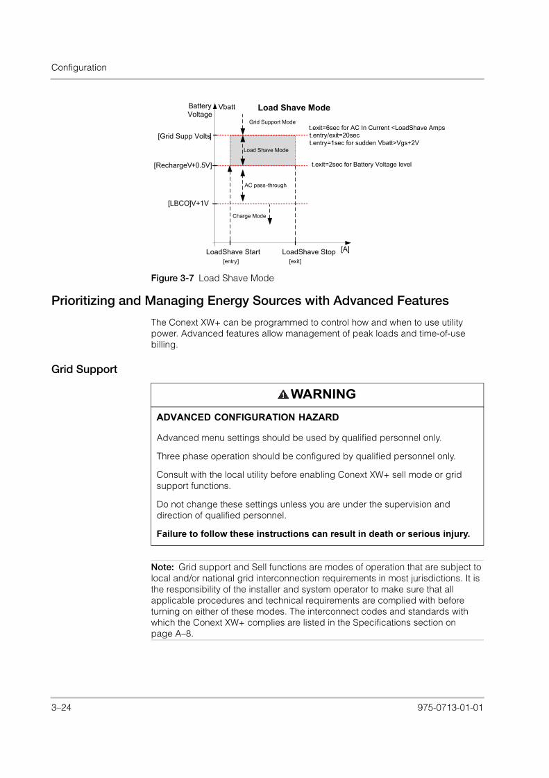
Configuration
XW_Europe_Operation.book Page 24 Thursday, July 30, 2015 4:12 PM
Prioritizing and Managing Energy Sources with Advanced Features
The Conext XW+ can be programmed to control how and when to use utility power. Advanced features allow management of peak loads and time-of-use billing.
Grid Support
Figure 3-7 Load Shave Mode
Load Shave Mode
BatteryVoltage
[A]
[Grid Supp Volts]
Load Shave Mode
[LBCO]V+1V
Grid Support Mode
Charge Mode
[RechargeV+0.5V]
LoadShave Start LoadShave Stop
t.exit=2sec for Battery Voltage level
t.entry/exit=20sect.entry=1sec for sudden Vbatt>Vgs+2V
t.exit=6sec for AC In Current <LoadShave Amps
AC pass-through
Vbatt
[entry] [exit]
WARNING
ADVANCED CONFIGURATION HAZARD
Advanced menu settings should be used by qualified personnel only.
Three phase operation should be configured by qualified personnel only.
Consult with the local utility before enabling Conext XW+ sell mode or grid support functions.
Do not change these settings unless you are under the supervision and direction of qualified personnel.
Failure to follow these instructions can result in death or serious injury.
Note: Grid support and Sell functions are modes of operation that are subject to local and/or national grid interconnection requirements in most jurisdictions. It is the responsibility of the installer and system operator to make sure that all applicable procedures and technical requirements are complied with before turning on either of these modes. The interconnect codes and standards with which the Conext XW+ complies are listed in the Specifications section on page A–8.
3–24 975-0713-01-01

Grid Support Settings
XW_Europe_Operation.book Page 25 Thursday, July 30, 2015 4:12 PM
The grid support mode allows the Conext XW+ to support local loads by converting excess capacity from external DC sources connected to its battery bank. Examples of external DC sources are solar charge controllers and batteries.
For Grid Support to function, Grid Support must be enabled on the Setup menu and the battery voltage must be above the Grid Supp Volts setting.
There are two modes of operation within Grid Support.
Grid Support enabled, Sell disabled In this mode, available excess DC power is converted and used to power local loads. No power is exported to the utility. If the local load demand exceeds the available power from the external DC sources, power is then drawn from the utility to support the load. However, if the local load demand is less than the power available from external DC sources, the net excess power from the external DC sources is not converted and hence not used.
Grid Support enabled, Sell enabled In this mode, all available excess DC power is first used to power local loads. Any remaining power is exported to the utility grid.
Grid Support and Battery Charging
Charge Cycle settings
With the charger enabled, the Conext XW+ enters Grid Support mode only after completing a charge cycle when it is first powered up or reconnected to the grid. It is recommended to set the Charge Cycle to 2-stage (default) to allow Grid Support to function immediately after the Absorption charge stage. See “Charger Settings Menu” on page 3–9.
Grid Support modes
Grid Support can be configured to operate in one of two modes:
Grid Support with DC Sources Not Communicating Over Xanbus This setup is suitable for use with DC sources (such as wind turbines, DC generator sets, fuel cells, and so on) that do not communicate with the Conext XW+ through Xanbus or for mixed systems which have both Xanbus-connected Conext Solar Charge Controllers and other DC sources (such as those listed above). Grid Supp Volts is set 0.5 volts below the voltage provided by the DC source (typically the float voltage setting of the DC source or charge controller). Schneider does not provide support for these energy sources.
In a ‘fixed’ battery voltage system configuration, the Conext XW+ manages the battery voltage to the Grid Supp Volts setting. This is done by converting the available DC power to AC power to support the AC loads attached to the inverter output or exports to the utility grid (AC1). Because the battery bank voltage may not reach bulk/absorption voltages in this mode, it is recommended to occasionally force a full charge cycle by either temporarily disabling grid support or forcing a bulk charge cycle from the grid (see “Force Chg” on the“Conext XW+ Setup Menu” on page 3–2.)
Enhanced Grid Support with Conext MPPT Solar Charge Controllers This setup is suitable for Conext Systems with only Conext MPPT Solar Charge Controller(s) networked to Conext XW+ units through Xanbus. In this configuration, Grid Supp Volts is set above the charge controller’s Equalization voltage (for example, 64 volts).
975-0713-01-01 3–25
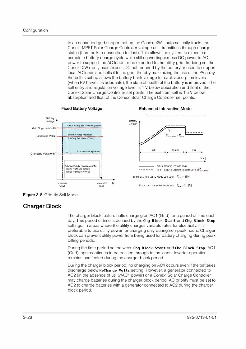
Configuration
XW_Europe_Operation.book Page 26 Thursday, July 30, 2015 4:12 PM
In an enhanced grid support set up the Conext XW+ automatically tracks the Conext MPPT Solar Charge Controller voltage as it transitions through charge states (from bulk to absorption to float). This allows the system to execute a complete battery charge cycle while still converting excess DC power to AC power to support the AC loads or be exported to the utility grid. In doing so, the Conext XW+ only uses excess DC not required by the battery or used to support local AC loads and sells it to the grid, thereby maximizing the use of the PV array. Since this set up allows the battery bank voltage to reach absorption levels (when PV harvest is adequate), the state of health of the battery is improved. The sell entry and regulation voltage level is 1 V below absorption and float of the Conext Solar Charge Controller set points. The exit from sell is 1.5 V below absorption and float of the Conext Solar Charge Controller set points.
Figure 3-8 Grid-tie Sell Mode
Charger Block
The charger block feature halts charging on AC1 (Grid) for a period of time each day. This period of time is defined by the Chg Block Start and Chg Block Stop settings. In areas where the utility charges variable rates for electricity, it is preferable to use utility power for charging only during non-peak hours. Charger block can prevent utility power from being used for battery charging during peak billing periods.
During the time period set between Chg Block Start and Chg Block Stop, AC1 (Grid) input continues to be passed through to the loads. Inverter operation remains unaffected during the charger block period.
During the charger block period, no charging on AC1 occurs even if the batteries discharge below ReCharge Volts setting. However, a generator connected to AC2 (in the absence of utility/AC1 power) or a Conext Solar Charge Controller may charge batteries during the charger block period. AC priority must be set to AC2 to charge batteries with a generator connected to AC2 during the charger block period.
Fixed Battery Voltage Enhanced Interactive Mode
Re-Entry Sell Mode +[Tdelay]
Battery Voltage
[V]
[Grid Supp Volts]
[Grid Supp Volts]-0.5VExit Sell Mode +[Tdelay ]
[Grid Supp Volts]+2V
Battery Voltage Regulation
Advanced/Adv Features config :[Tdelay]= 20 sec default[Tdelay]=Enable: 40 sec
Fast Re-Entry Sell Mode: no [Tdelay]
Vbat>GSV Vbat<GSV[entry] [exit]
3–26 975-0713-01-01
Grid Support Settings
XW_Europe_Operation.book Page 27 Thursday, July 30, 2015 4:12 PM
If the charger is operating (that is, in float, absorption, bulk, or equalize stage) at the Chg Block Start time, charging on AC1 stops immediately and the charger enters an idle state identical to no float (see “Two-Stage” on page 3–14). When the charger block period is over, the charger does not resume the charge stage that was interrupted. Instead, if the batteries are above the ReCharge Volts setting, the charger remains idle.
If the battery voltage falls below the ReCharge Volts setting during the charger block period, the Conext XW+ begins a new charge cycle with the bulk stage after the charger block period has expired (at the Chg Block Stop time).
For example, charger block is set to start at 5:00 PM and end at 8:00 PM. If the Conext XW+ is charging from AC1, charging stops at 5:00. When charger block ends at 8:00, the Conext XW+ does not automatically resume charging. The unit first measures the battery voltage. If the voltage is below the ReCharge Volts setting, then the Conext XW+ starts a new charge cycle from bulk. If the battery voltage is above the ReCharge Volts setting, the Conext XW+ remains idle and continues passing through AC to the loads. The Conext XW+ also keeps measuring the battery voltage as before to determine whether to start a new charge cycle.
Peak Load Shaving (PLS)
Many utilities impose a surcharge on their customers based on the peak load used by a facility. To reduce utility peak demand charges, the inverter can be configured (using the Load Shave Amps setting) to limit the maximum draw the AC loads place on the utility. The inverter can be programmed to provide power above a specified level to avoid the surcharge. When the utility current draw reaches the maximum level, the inverter assists by sourcing power from the batteries to the loads.
For PLS to be effective, all loads must be connected to the inverter. For large loads, multiple (or stacked) inverters may be required.
To help the batteries supplement the power requirements of the connected load, an additional source of power (solar, wind, or hydroelectric) is recommended.
The default PLS setting for Time in Float is zero. In this case, PLS is only entered/exited as programmed within the time window.
When the Time in Float is different than zero, PLS shall start only if the battery amperage remained at the specified level for the configured time.
Example: Load Shave=Enabled, LoadShaveAmps=10 A, LoadShaveStart=6:00pm, LoadShaveStart=9:00pm, Time in Float=60 min, PLS Dly 2h= Enabled.
With these example settings, the Conext XW+ would enter PLS within the configured window of time only if the battery was charged from MPPT in Float (including Absorption) for 2 hours.
Time-of-Use Metering
Utilities use time-of-use metering to determine utility charges during peak usage hours and to impose a surcharge. The Conext XW+ can be configured (using the Load Shave Start, Load Shave Stop and Charger Block settings) to overcome
975-0713-01-01 3–27

Configuration
XW_Europe_Operation.book Page 28 Thursday, July 30, 2015 4:12 PM
these peak charges by using utility power to charge the battery bank during the inexpensive energy hours and consuming the battery energy during expensive energy hours.
For example, if Charger Block is set between 9:00 AM and 10:00 PM and Load Shave is set between 6:00 PM and 9:00 PM, charging on AC1 stops at 9:00 AM and continues to pass utility AC through to the loads. If charging is required during the charger block period, and AC Priority is set to AC2, the Conext XW+ can use any AC source connected to AC2. Loads will transfer to the AC source on AC2 as well. The inverter connects to the utility grid at 6:00 PM and supports loads using the batteries. The inverter continues to run until 9:00 PM. The Conext XW+ then stops supporting the utility grid and passes utility AC through to the loads. At 10:00 PM utility AC begins maintaining the batteries based on the battery charger settings.
The above example allows an external renewable energy source to be utilized as a primary charging source during a desired time window. The charger (using utility AC connected to AC1) can then be used to supplement the battery charging when the utility rates are low.
When using the system for time-of-use metering, the system should be designed with a battery capacity large enough to support loads during the entire peak rate period without reaching the Low Batt Cut Out setting.
Self-Consumption
PLS can also be used with time-of-use metering to support self-consumption. In the self-consumption mode of operation, the Conext XW+ delays Peak Load Shave mode by a fixed time of 2 hours. This is done by allowing a priority for the MPPT solar charge controller to charge the battery bank.
This configuration can be selected under the Conext XW+ menu by selecting Advanced Settings/Advanced Features/PLS DLY 2H=Enabled. The default setting for PLS DLY 2H is Disabled.
Note: If the batteries reach the Low Battery Cut Out setting, the Conext XW+ automatically reconnects to the utility grid to maintain the connected load.
3–28 975-0713-01-01
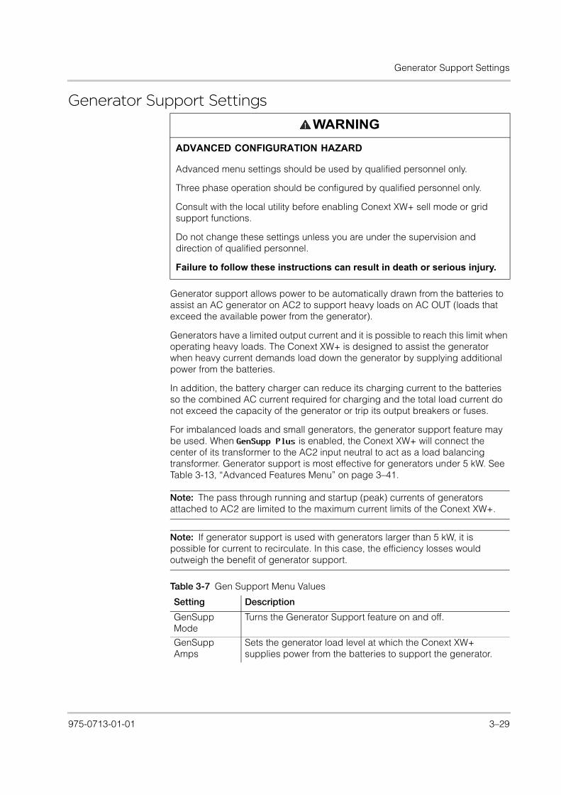
Generator Support Settings
XW_Europe_Operation.book Page 29 Thursday, July 30, 2015 4:12 PM
Generator Support Settings
Generator support allows power to be automatically drawn from the batteries to assist an AC generator on AC2 to support heavy loads on AC OUT (loads that exceed the available power from the generator).
Generators have a limited output current and it is possible to reach this limit when operating heavy loads. The Conext XW+ is designed to assist the generator when heavy current demands load down the generator by supplying additional power from the batteries.
In addition, the battery charger can reduce its charging current to the batteries so the combined AC current required for charging and the total load current do not exceed the capacity of the generator or trip its output breakers or fuses.
For imbalanced loads and small generators, the generator support feature may be used. When GenSupp Plus is enabled, the Conext XW+ will connect the center of its transformer to the AC2 input neutral to act as a load balancing transformer. Generator support is most effective for generators under 5 kW. See Table 3-13, “Advanced Features Menu” on page 3–41.
WARNING
ADVANCED CONFIGURATION HAZARD
Advanced menu settings should be used by qualified personnel only.
Three phase operation should be configured by qualified personnel only.
Consult with the local utility before enabling Conext XW+ sell mode or grid support functions.
Do not change these settings unless you are under the supervision and direction of qualified personnel.
Failure to follow these instructions can result in death or serious injury.
Note: The pass through running and startup (peak) currents of generators attached to AC2 are limited to the maximum current limits of the Conext XW+.
Note: If generator support is used with generators larger than 5 kW, it is possible for current to recirculate. In this case, the efficiency losses would outweigh the benefit of generator support.
Table 3-7 Gen Support Menu Values
Setting Description
GenSupp Mode
Turns the Generator Support feature on and off.
GenSupp Amps
Sets the generator load level at which the Conext XW+ supplies power from the batteries to support the generator.
975-0713-01-01 3–29

Configuration
XW_Europe_Operation.book Page 30 Thursday, July 30, 2015 4:12 PM
For default settings, see “Gen Support Menu” on page B–5.
Figure 3-9 Gen Support Mode Graph
Note: Ensure that the battery bank has sufficient energy to support your loads for the anticipated time period, otherwise draining the battery to LBCO may put the system in Fault mode.
Table 3-8 Gen Support Menu Values
Gen supportmode
Battery Voltage
[A]
AC In Current >GenSupportA
AC In Current <GenSupportA
V[LBCO]
V[DC max]
[LBCO]+2V
[exit]
[entry]
Gen Support Mode
Setting Description
GenSupp Mode
Turns the generator support feature on and off.
GenSupp Amps
Sets the generator load level at which the Conext XW+ begins to convert external DC energy and supply additional AC power in parallel to loads on AC Out.
3–30 975-0713-01-01

Auxiliary Output Settings
XW_Europe_Operation.book Page 31 Thursday, July 30, 2015 4:12 PM
Auxiliary Output Settings
The Aux menu allows you to enable and set the auxiliary output. The auxiliary output provides 12 volts DC at 250 milliamps to power a relay, indicator light, or alarm.
For default settings, see “Aux Menu” on page B–5.
Note: Changing the Trigger Level resets the auxiliary output. If an auxiliary output trigger is active, changing the trigger level will clear the trigger.
Table 3-9 Aux Menu Values
Setting Description
Manual Aux Sets the state of the auxiliary output. ManualOn or ManualOff allow manual control of the Auxiliary Output. When set to Automatic, a trigger source can then be selected.
Active Lvl Sets the mode (polarity) of the auxiliary output. When triggered, the output can be active high (12 V output turns on) or active low (output is high until the trigger turns it off).
Trigger Src Sets the desired condition (Trigger Source) to activate the auxiliary output. The Trigger Source options are LowBattV, HighBattV, LowBattTemp, HighBattTemp, and Fault.
Trigger Level
Sets the voltage or temperature level (depending on the selected trigger source) at which the auxiliary output is activated. If the selected Trigger Source is a Battery Voltage, the range also varies according to the nominal battery voltage of your system.
Trigger Delay
Sets a delay period between when the trigger occurs and when the auxiliary output is activated.
Clear Level Sets the voltage or temperature level (depending on the selected trigger source) at which the auxiliary output becomes inactive.
Clear Delay Sets a delay period between when the Clear Level setting occurs and when the auxiliary output becomes inactive.
Charge Bulk Exit
Exits charge bulk mode. In charge bulk mode, the XW operates as a constant power source to the battery bank.
Charge Absorption Exit
Exits charge absorption mode and starts the following mode, depending on whether the unit is set to two or three-stage charge.
Heatsink temperature
Both high and low end within the heatsink temperature range are configurable. The voltage will be adjusted accordingly when the temperature goes out of range (e.g. the voltage is lowered when the temperature gets too high).
State of Charge (SoC)
This feature works only in conjunction with the Conext Battery Monitor. A voltage change is triggered when the state of charge falls outside of the range of 25-90% of total battery charge. When triggered, the output can be active high (12 VDC output turns on) or active low (output is high until the trigger turns it off).
TOD (Time of Day)
Time setting. Can be set to a value between 12:00 AM and 11:59 PM.
975-0713-01-01 3–31

Configuration
XW_Europe_Operation.book Page 32 Thursday, July 30, 2015 4:12 PM
Trigger Source Descriptions
Low Batt Voltage Activates the auxiliary output when the battery voltage falls below Low Batt Voltage after the trigger delay time. The auxiliary output turns off when the battery voltage rises above the clear setting after the Clear Delay time. Use this setting if the auxiliary output needs to control a relay to disconnect loads from a battery or to activate a low battery voltage alarm such as a buzzer or light.
High Batt Voltage Activates the auxiliary output when the battery voltage rises above Hi Batt Voltage for the trigger delay time. The auxiliary output turns off when the battery voltage falls below the clear setting for the Clear Delay time. This setting is useful for:
• Installations that have another external charging source such as a wind generator or hydro generator connected directly to the batteries. The Conext XW+ auxiliary output can control a relay to disconnect the external charging source from the battery or control a relay to turn on a diversion load.
• Activating a high battery voltage alarm such as a buzzer or light.
• Activating a vent fan to ventilate the battery compartment.
Low Batt Temp Activates the auxiliary output when the battery temperature falls below Low Batt Temp for the trigger delay time. The auxiliary output turns off when the battery temperature rises above the clear setting for the Clear Delay time. Battery temperature is measured with a battery temperature sensor. Do not use this setting if a battery temperature sensor is not installed.
High Batt Temp Activates the auxiliary output when the battery temperature rises above Hi Batt Temp for the trigger delay time. The auxiliary output turns off when the battery temperature falls below the clear setting for the Clear Delay time. Battery temperature is measured with a battery temperature sensor. Do not use this setting if a battery temperature sensor is not installed. With this setting, the auxiliary output can turn on a fan to vent the battery compartment.
Fault Activates the auxiliary output when a fault occurs. The auxiliary output clears when the fault is cleared.
State of Charge (SoC) fThis feature works in conjunction with the Conext Battery Monitor. This auxiliary output is triggered when the state of charge falls outside of the range of 25-90% of total battery charge.
3–32 975-0713-01-01

Multi-Unit Config Menu
XW_Europe_Operation.book Page 33 Thursday, July 30, 2015 4:12 PM
Multi-Unit Config Menu
The Multi-Unit Config menu configures the Conext XW+ to operate as a part of a multi-unit installation.
When installing a multi-unit system, each setting on the Multi-Unit Config menu (except for Dev Name) must be configured for each Conext XW+ in the system. The settings should be configured in the following order:
• Dev Number• Inverter Mode• Connections
WARNING
ADVANCED CONFIGURATION HAZARD
Advanced menu settings should be used by qualified personnel only.
Three phase operation should be configured by qualified personnel only.
Consult with the local utility before enabling Conext XW+ sell mode or grid support functions.
Do not change these settings unless you are under the supervision and direction of qualified personnel.
Failure to follow these instructions can result in death or serious injury.
Note: Accessing this menu automatically places the Conext XW+ in standby mode and de-energizes the circuits on inverter output. When entering the Multi-Unit Config menu, the unit identifies itself by flashing the front panel lights. After exiting the Multi-Unit Config menu, the Conext XW+ returns to operating mode and the front panel lights stop flashing.
975-0713-01-01 3–33

Configuration
XW_Europe_Operation.book Page 34 Thursday, July 30, 2015 4:12 PM
Setting the Device Name
The Dev Name setting allows you to customize the name of the Conext XW+ as it is displayed on other screens and menus.
The available characters are:
• A to Z
• a to z
• 0 to 9
• space
To customize the Conext XW+ name:
1. On the device setup menu, select Advanced Settings.
If Basic Settings appears instead of Advanced Settings on the device setup menu, display Advanced Settings by pressing Enter + Up arrow + Down arrow at the same time.
2. Select the Multi-Unit Config menu.
3. Select Dev Name.
4. Press Enter.
The last letter of the Conext XW+ name is highlighted.
Table 3-10 Multi-Unit Config Menu
Item Description Default Range
Dev Name Allows customization of the default device name. This setting is optional and does not affect operation. See “Setting the Device Name” on page 3–34.
n/a n/a
Dev Number Allows setting of a unique unit number in a multi-unit system. See “Setting the Device Number” on page 3–35.
00 00–31
Inverter Mode
For a multi-unit, single-phase system to operate, one Conext XW+ must be configured to 1Ph Master and the rest as 1Ph Slave, otherwise a system-wide fault is asserted.
For a three-phase system, see “Three-Phase Configuration” on page 3–36.
1PhMaster For single-phase models: 1Ph Master, 1Ph Slave. For three-phase systems, see “Three-Phase Configuration” on page 3–36.
Connections Select to display the Connections menu.
See “Connections Menu” on page 3–38.
n/a n/a
Note: Increasing the number of characters in a device name may cause other text on the same line to run off the edge of the screen. Device names should be limited to 10 characters or less.
3–34 975-0713-01-01

Multi-Unit Config Menu
XW_Europe_Operation.book Page 35 Thursday, July 30, 2015 4:12 PM
5. Begin customizing the device name.
• To change the character, press the up or down arrow button. Holding down the button causes the characters to scroll more quickly.
• To delete the character, press Exit.
• To add characters, press Enter.
6. When the correct character is shown, press Enter to select it.
7. After pressing Enter to select the last character of your customized device name, press Enter again to return to the menu.
Setting the Device Number
When several devices of the same type are installed in the Xanbus network, setting the device number is required to give a Xanbus-enabled device a unique identity. When each identical device has a unique number, the Conext SCP can correctly identify and display status information for each device. A device number consists of two digits ranging from 00 (default) to 31.
If only one of each type of device is installed in the networked power system, a device number is not needed. However, setting the device number to a value other than 00 is recommended in case you need to use the Restore Defaults command (which resets the device number to 00). After performing the command, checking that the device number has returned to 00 indicates that the command was successfully completed.
To set the Conext XW+ device number:
1. On the Conext XW+ Setup menu, select Advanced Settings.
If Basic Settings appears instead of Advanced Settings on the Setup menu, display Advanced Settings by pressing Enter + Up arrow + Down arrow simultaneously.On the Advanced Settings menu, select Multi-Unit Config and press Enter.
2. On the Multi-Unit Config menu, select Dev Number. See Figure 3-10.
3. Press Enter to highlight the instance number.
4. Use the up and down arrow buttons to adjust the two-digit identifier number.
5. Press Enter.
Note: It is also possible to change the device name using the Conext System Control Panel and Conext Configuration Tool. Please refer to the respective Owner’s Guides for these products for further information.
Figure 3-10 Setting a Device Number
XW+ 8548 01:Multi
Dev Number[XW1]
[01][1PhSlave]
975-0713-01-01 3–35

Configuration
XW_Europe_Operation.book Page 36 Thursday, July 30, 2015 4:12 PM
Three-Phase Configuration
When installed in a three-phase system, the Conext XW+ requires a designated master unit on each phase. If there is not a master unit on each phase, a system-wide fault (F66) is asserted. Before setting up a three-phase system, confirm that the Conext XW+ units have been installed and wired for three-phase. See the Conext XW+ Installation Guide for further information.
The Conext XW+ is capable of supporting three-phase systems and supports different configurations for grid-tie and off-grid applications. The Conext XW+ will support either three units or six units in a three-phase grouping when deployed as a grid-tie backup system. The power adjustment on each phase must be made at the time of commissioning and under supervision of a utility representative. Off-grid deployment of six or more Conext XW+ units in a single three-phase grouping is not supported.
For off-grid applications, the Conext XW+ is deployed in clusters of three units (one per phase) for three-phase off-grid systems. Up to four clusters can support off-grid using an external AC contactor system for managing the AC bus line between sources AC and consumption loads. For the installation, setup and commissioning of multi-cluster systems, refer to the Conext XW+ Installation Guide.
Note: The XanBus communications protocol supports a maximum of twelve Conext XW+ units in a single network.
To set up a three-phase system:
1. Follow the instructions in the Conext XW+ Installation Guide to Daisy chain XW-phA, XW-phB, and XW-phC at each unit’s AC sync port and connect an AC sync cable between the second AC sync port in unit 2 and an AC sync port in unit 3.
2. On the Conext SCP, select XWabcd 00 > Advanced Settings > Multi-Unit Config (where abcd is the model number 6848 or 5548).
3. Optionally, change the device name or device number. Device numbers are suggested to facilitate identifying devices on the system as well as phase association from a device’s name and number. Naming devices may be
WARNING
ADVANCED CONFIGURATION HAZARD
Advanced menu settings should be used by qualified personnel only.
Three phase operation should be configured by qualified personnel only.
Consult with the local utility before enabling Conext XW+ sell mode or grid support functions.
Do not change these settings unless you are under the supervision and direction of qualified personnel.
Failure to follow these instructions can result in death or serious injury.
3–36 975-0713-01-01

Multi-Unit Config Menu
XW_Europe_Operation.book Page 37 Thursday, July 30, 2015 4:12 PM
customized as desired. Conflicting device names are allowed and will not cause faults in the system, however giving them unique names is highly recommended.
4. Under Invtr Mode, select:
• 3Ph L1Master for unit 1 or Phase A
• 3Ph L2Master for unit 2 or Phase B
• 3Ph L3Master for unit 3 or Phase C
5. Optionally, up to one additional Conext XW+ may be installed in parallel on each phase (for grid-tie systems only). Additional units are called “slave units”. This configuration allows for a maximum of 6 units in a single grouping. For larger groupings of up to 12 total units, see the Off-Grid Systems Guide for Conext XW+ available at solar.schneider-electric.com/solar. The slave unit on each phase (parallel) must be configured as 3PhL1Slave, 3PhL2Slave, and 3PhL3Slave respectively. A maximum of two units per phase is allowed. Under Invtr Mode, select:
• 3Ph L1Slave for unit 4 or Phase A
• 3Ph L2Slave for unit 2 or Phase B
• 3Ph L3Slave for unit 3 or Phase C
6. Confirm that the Grid or Gen wiring has the correct A, B, C phase sequence with the three Conext XW+ Inverter/Chargers. If the phase sequence is incorrect, the Conext system will not qualify the input AC voltage.
7. Put the wiring compartment cover back in place, and then power up the converted units. Perform an AC voltage measurement in invert mode. Make sure the output voltage is within 220 – 230 VAC.
Table 3-11 Example Three-phase Inverter Assignments
Line or Phase Inverter Mode Role Assignmenta
a.Each phase can support one master unit and one slave unit.
Suggested Device Number
Line-1 or Phase-A 3Ph L1 Masterb
b.The L1 Master is also the master inverter/charger for the entire system. The system masterbroadcasts phase synchronizing pulses through its sync port, and each phase master con-trols the other units on its respective phase.
Phase-A or Line-1 Master
10
3Ph L1 Slavec
c.The slave unit in each phase is optional.
Phase-A or Line-1 Slave 11
Line-2 or Phase-B 3Ph L2 Master Phase-B or Line-2 Master
20
3Ph L2 Slave Phase-B or Line-2 Slave 21
Line-3 or Phase-C 3Ph L3 Master Phase-C or Line-3 Master
30
3Ph L3 Slave Phase-C or Line-3 Slave 31
Figure 3-11 Three-Phase Configuration Example
975-0713-01-01 3–37

Configuration
XW_Europe_Operation.book Page 38 Thursday, July 30, 2015 4:12 PM
Connections Menu
The Connections menu contains additional settings to allow the Conext XW+ to function as part of a multi-unit networked system.
Setting the connections for a Xanbus-enabled device provides a way of identifying non-network associations for Xanbus-enabled devices (see Figure 3-12) and enhancing networked power system management. When connections are set, devices of different types become associated and can share sources, e.g. a common DC input source, or a common grid/generator source.
In multi-unit networked systems, multiple inverter/chargers can be stacked to produce increased charge current. To achieve this functionality, the devices must be configured to the same DC connection, such as House Battery Bank 1. The units will collaborate on battery charging by communicating with other units on this shared DC connection.
WARNING
ADVANCED CONFIGURATION HAZARD
Advanced menu settings should be used by qualified personnel only.
Three phase operation should be configured by qualified personnel only.
Consult with the local utility before enabling Conext XW+ sell mode or grid support functions.
Do not change these settings unless you are under the supervision and direction of qualified personnel.
Failure to follow these instructions can result in death or serious injury.
Note: When configuring clusters of three Conext XW+ units (or a grouping of up to six in a grid-tie application), each cluster’s DC connections must be set to the same battery bank. If one of the units is set with a different DC connection, a system configuration fault (F66) occurs.
Table 3-12 Connections Menu
Item Description
DCConn DC Input and Output connection. This is the common DC connection shared between inverter/chargers, charge controllers, and referenced by the Conext Automatic Generator Start.
ACOut AC Output connection. This connection specifies a common AC output connection shared between inverter/chargers. The AC Out connection must be configured so that the Conext XW+ units know if they are connected to the same load or not. If connected to the same load, select the same name on all units; for example, ACLoad1. If connected to separate load banks, use different names for the AC Out connection on each unit; for example, ACLoad1 on one unit and ACLoad2 on the other.
AC1 AC1 input connection. This connection specifies a common AC Line 1 input for multiple inverter/chargers.
3–38 975-0713-01-01

Copying Settings From Another Unit
XW_Europe_Operation.book Page 39 Thursday, July 30, 2015 4:12 PM
For default settings, see “Connections Menu” on page B–6.
Copying Settings From Another Unit
The Copy from command allows quick configuration of an Conext XW+. After selecting another Conext XW+ in the system to copy settings from, common parameters are copied from the selected Conext XW+ to the Conext XW+ being configured.
The following settings are copied from the selected unit:
AC2 AC2 input connection. This connection specifies a common AC Line 2 input for multiple inverter/chargers.
Table 3-12 Connections Menu
Item Description
Figure 3-12 Conext XW+ Connections Representation
WARNING
ADVANCED CONFIGURATION HAZARD
Advanced menu settings should be used by qualified personnel only.
Three phase operation should be configured by qualified personnel only.
Consult with the local utility before enabling Conext XW+ sell mode or grid support functions.
Do not change these settings unless you are under the supervision and direction of qualified personnel.
Failure to follow these instructions can result in death or serious injury.
L N
AC LOAD
GRID (AC1)
GEN (AC2)
AC OUT AC IN AC IN
L N L N
DC Connection: Select House Battery 1 to 6
AC Out Connection: Select AC Load 1 to 10
AC1 Connection: Select Grid 1 to 10, Gen 1 to 10
AC2 Connection: Select Grid 1 to 10, Gen 1 to 10
975-0713-01-01 3–39

Configuration
XW_Europe_Operation.book Page 40 Thursday, July 30, 2015 4:12 PM
• Inverter Settings
• Charger Settings
• AC Settings
• Grid Support Settings (except the Sell setting)
• Gen Support Settings
The following settings are not copied between units:
• Inverter Mode
• Device Number
• Device Name
• Auxiliary Output settings
Restoring the Conext XW+ to Factory Default Settings
The Restore Defaults command returns the Conext XW+ to factory default settings. After using the Restore Defaults command, the Conext XW+ is no longer configured for the power system.
To restore Conext XW+ default settings:
1. On the Advanced Setup menu, select Restore Defaults.
Warning W252 appears, asking to confirm the command.
2. To cancel the command, press Exit. To continue with the Restore Defaults command, press Enter.
NOTICE
RESTORING DEFAULTS
Do not restore defaults while the Conext XW+ is operating. De-energize the power system and disconnect the Conext XW+ AC input before restoring defaults. Reconfigure the Conext XW+ before reconnecting the AC input and re-energizing the power system.
Failure to follow these instructions can result in equipment damage.
Note: If a warning is already active in the system, selecting Restore Defaults brings up the Warnings list, with warning W252 at the top. Press Enter to view W252 and continue with the restore defaults process.
3–40 975-0713-01-01

Using the Advanced Features
XW_Europe_Operation.book Page 41 Thursday, July 30, 2015 4:12 PM
Using the Advanced FeaturesWARNING
ADVANCED CONFIGURATION HAZARD
Advanced menu settings should be used by qualified personnel only.
Three phase operation should be configured by qualified personnel only.
Consult with the local utility before enabling Conext XW+ sell mode or grid support functions.
Do not change these settings unless you are under the supervision and direction of qualified personnel.
Failure to follow these instructions can result in death or serious injury.
Table 3-13 Advanced Features Menu
Item Description
RPO Enables or disables the remote power off function. Enable this setting if an external switch has been connected to the Conext XW+ auxiliary port. See the Conext XW+ Installation Guide for more information about the auxiliary port.
Power Save When enabled, Power Save mode can reduce tare loss from the battery by reducing output from 230 volts to 210 volts when the loads are less than 100 watts. When the Conext XW+ detects loads higher than 100 watts, the inverter/charger produces the full 230 volts. Power Save mode is disabled by default.
Sell Dly 40s When enabled—and other conditions are satisfied—there will be a 40 second delay before the system starts selling power to the grid. When disabled, the default value of 20 seconds is used. This feature is useful when the battery voltage is not constant. It also helps avoid power fluctuations during sell.
As an exception, there will be zero time delay when the battery voltage suddenly rises to 2 V above Grid Supp Volts. For example, a wind turbine or micro-hydro connected to a small battery bank may create a sudden change on the battery voltage. In this case the system will immediately respond to convert the energy from the battery to grid.
AC_Coupling AC Coupling function is enabled by default (Advanced Features Menu) and should remain enabled except in cases where the DC voltage level is allowed to have large variations and the AC line frequency needs to remain constant.
Batt_Balance The Battery Balance function is disabled by default and is intended for use with inverters drawing power from a single battery bank. The Battery Balance function should be enabled when Conext XW+ units are used in multi-cluster systems with multiple battery banks. When enabled this feature helps balance the power draw across multiple battery banks.
975-0713-01-01 3–41

Configuration
XW_Europe_Operation.book Page 42 Thursday, July 30, 2015 4:12 PM
EXT_CONTACT
This feature is used in a multi-cluster configuration with external contactor for off-grid applications. Further details regarding the use of an external contactor can be found in the Conext Multi-Cluster Planning Guide (document part number: 975-0648-01-01).
PLS DLY 2h When enabled, PLS (Peak Load Shave) mode is delayed by 2 hours to allow the MPPT solar charge controller to charge the battery bank first, then when the timer of 2 hours expires, the unit enters PLS mode for AC load support.
Table 3-13 Advanced Features Menu
Item Description
3–42 975-0713-01-01

XW_Europe_Operation.book Page 1 Thursday, July 30, 2015 4:12 PM
4 Troubleshooting
Chapter 4, “Troubleshooting”, contains information and procedures for identifying and solving possible problems with the Conext XW+ Inverter/Charger.
Topics in this chapter include:• “General Troubleshooting Guidelines”
on page 4–2• “Inverter Applications” on page 4–2• “Inverter Troubleshooting” on page 4–4• “Battery Charger Troubleshooting” on
page 4–7• “Faults and Warnings” on page 4–10.

Troubleshooting
XW_Europe_Operation.book Page 2 Thursday, July 30, 2015 4:12 PM
General Troubleshooting Guidelines
This section will help you narrow down the source of any problem you may encounter. Please read the following troubleshooting steps:
1. Check for a Warning or Fault message on the Xanbus System Control Panel or a Fault code on the inverter information panel. If a message is displayed, record it immediately.
2. As soon as possible, create a detailed record of the conditions at the time the problem occurred. These details should include, but not be limited to, the following:
• Loads the Conext XW+ was running or attempting to run.
• Battery condition at the time of failure (for example battery voltage or temperature) if known.
• Recent sequence of events (for example, charging had just finished, utility grid had failed but the inverter did not start up).
• Any known unusual AC input factors such as low voltage or unstable generator output.
• Extreme conditions which may have existed at the time (temperature or moisture for example).
3. Attempt the solution corresponding to the Warning or Fault message indicated in Table 4-3 on page 4–11 or Table 4-6 on page 4–16.
4. If your inverter information panel or Xanbus SCP is not displaying a Fault light, check the following list to make sure that the present state of the installation allows proper operation of the unit. See also “Inverter Troubleshooting” on page 4–4 and “Battery Charger Troubleshooting” on page 4–7.
• Is the Conext XW+ located in a clean, dry, adequately ventilated area?
• Have the AC input breakers opened? If so, your pass through load may have exceeded the rating of one or more of the input breakers.
• Are the battery cables adequately sized and short enough? See the Conext XW+ Installation Guide for more information.
• Is the battery in good condition, and are all DC connections tight?
• Are the AC input and output connections and wiring in good condition?
• Are the configuration settings correct for your particular installation?
• Are the display panel and the communications cable properly connected and undamaged?
• Are the battery temperature sensor and its cable properly connected and undamaged?
5. Contact Schneider Electric Customer Service for further assistance. Please be prepared to describe details of your system installation and provide the model and serial number of the unit. See page ii for contact information.
Inverter ApplicationsThe Conext XW+ performs differently depending on the AC loads connected to it. If you are having problems with any of your loads, read this section.
4–2 975-0713-01-01

Inverter Applications
XW_Europe_Operation.book Page 3 Thursday, July 30, 2015 4:12 PM
Resistive Loads
Resistive loads are the easiest and most efficient to drive. Voltage and current are in phase, which means they are in step with one another. Resistive loads generate heat in order to accomplish their tasks. Toasters, coffee pots, and incandescent lights are typical resistive loads. It is usually impractical to run larger resistive loads—such as electric stoves and water heaters—from an inverter due to their high current requirements. Even though the inverter may be able to accommodate the load, the size of battery bank will limit inverter run time.
Motor Loads
Induction motors (AC motors without brushes) require up to six times their running current on start up. The most demanding are those that start under load (for example, compressors and pumps). Of the capacitor start motors (typical in tools such as drill presses and band saws), the largest you can expect to run is 1 horsepower. Universal motors are generally easier to start. Check that the Locked Rotor Amps (LRA) rating of the motor load does not exceed the maximum surge current rating of the inverter. Since motor characteristics vary, only testing will determine whether a specific load can be started and how long it can be run.
If a motor fails to start within a few seconds or loses power after running for a time, it should be turned off. When the inverter attempts to start a load that is greater than it can handle, the inverter may shut down from an AC Overload fault.
Problem Loads
Very Small Loads
IIf the power consumed by a device is less than the threshold of the search mode circuitry, and search mode is enabled, the inverter will not run. Most likely the solution will be to disable Search mode or lower the sense threshold. (See “Using Search Mode” on page 3–8.)
Fluorescent Lights and Power Supplies
Some devices cannot be detected when scanned by search mode circuitry. Small fluorescent lights are the most common example. Some computers and sophisticated electronics have power supplies that do not present a load until line voltage is available. When this occurs, each unit waits for the other to begin. To drive these loads, either a small companion load like a light bulb rated for more than the Search Watts setting must be used to bring the inverter out of search mode, or the inverter may be programmed to remain on by disabling search (See “Using Search Mode” on page 3–8).
Clocks
You may notice that your clocks are not accurate. Some of the clocks on your appliances may reset when the Conext XW+ is in search mode. Disabling search mode will resolve this issue.
975-0713-01-01 4–3

Troubleshooting
XW_Europe_Operation.book Page 4 Thursday, July 30, 2015 4:12 PM
Searching
When the inverter is in search mode, it may fail to start some loads even though the rated wattage on the load is more than the Search Watts setting. Disable search or apply an additional load (companion load) to make the inverter exit search mode.
Inverter Troubleshooting
To determine the cause of an inverter error condition, refer to the troubleshooting table below for possible solutions.
Table 4-1 Troubleshooting Common Problems
Problem Possible cause Solution
Unit will not power on (no LEDs are on) and the inverter information panel is blank or off.
Unit was turned off using startup/shutdown button on front panel.
DC voltage on the inverter’s DC terminals is incorrect.
Turn the unit on again.
Check the battery voltage, fuses or breakers and DC cable connections to the inverter. If the DC voltage on the inverter’s DC terminals is correct, have unit serviced.
Unit goes into invert mode and starts producing AC output, but stops quickly (several attempts made).
Excessive load on output.
Unit is in over-temperature protection and needs to cool down.
Remote Power Off signal is present.
Reduce loads.
Stop inverting by putting the inverter into Standby mode, and then allow the unit to cool and increase ventilation. If necessary, replace the foam air filter on the bottom of the unit.
Release or reset the Remote Power Off switch.
4–4 975-0713-01-01

Inverter Troubleshooting
XW_Europe_Operation.book Page 5 Thursday, July 30, 2015 4:12 PM
No AC power output.
The inverter information panel displays .
Open AC output breakers or fuses and bad output wire connections.
Inverter is disabled. Re-enable inverter.
Check the Load AC Voltage status on the SCP Meters screen and check AC voltage on the inverter AC Out terminal block.
If the Meters screen shows correct AC voltage but there is no AC voltage on the inverter AC Out terminal block, check for loose connections on the inverter terminal block. If connections are not loose, the inverter may need to be serviced.
If there is correct AC voltage on the Meters screen and on the inverter AC terminal block, check for open AC output breakers or fuses and bad output wire connections.
If AC voltage on the Meters screen or inverter AC terminal block is incorrect, have unit serviced.
No AC power output.
The inverter information panel displays .
AC load too small for Search Mode circuit to detect.
Reduce Search Watts setting, increase load above Search Watts setting, or disable Search on the Setup menu.
If the AC1 LED is on, check inverter output connections and voltage.
Low AC power output or low surge power. INVERT LED is on.
AC inductive loads are not running at full speed.
Insufficient DC current being provided to the inverter to operate the AC loads.
Check the battery voltage, fuses or breakers and cable connections.
Make sure the battery bank is sufficient (check for low DC voltage while running the load).
Make sure the cable length and size is correct (see the Conext XW+ Installation Guide for correct cable). Tie the battery cables together to reduce inductance.
Problem Possible cause Solution
975-0713-01-01 4–5

Troubleshooting
XW_Europe_Operation.book Page 6 Thursday, July 30, 2015 4:12 PM
Inverter turns on and then off or does not turn on at all.
Search Watts setting is too low or high.
Potential problem loads for search mode:
• Incandescent lights have a higher starting wattage when the filament is cold than the continuous rating of the bulb.
• Fluorescent bulbs draw little power until the mercury vapor begins to conduct enough current to light the tube.
• Other loads: Some appliances draw power even when turned off: TVs with instant-on circuits and VCRs, for example.
If the search sensitivity is set higher than the combined loads, then connect an auxiliary load to bring the inverter out of Search Mode before the appliances can be turned on.
If the sensitivity is set lower than the combination of the loads, the loads will remain on and excess battery drain will occur since the inverter will not ever idle.
Another solution is to turn the item off at the wall; use an extension cord with a rocker switch, a switch at the outlet, or an appropriate circuit breaker.
The utility grid is not dropping out, but the unit is disconnecting from the grid.
The AC voltage or frequency provided to the inverter input is outside the AC Setting voltage or frequency range.
Adjust the AC1 voltage and frequency settings (see “AC Input Settings” on page 3–21). Raise the high voltage and frequency settings, and lower the low voltage and frequency settings. If Grid support is enabled, these limits are over-ridden by the default anti-islanding AC parameters.
The inverter connects to the grid and can charge normally. In a grid interactive mode (Grid Support enabled), the unit is experiencing excessive anti-islanding faults during periods of high sell amperage.
The impedance of the AC connection to the inverter is too high for the power being sold to the grid. The impedance may be on the high end if the installation is too far from the utility point of common connection or if the wires are too small between the Conext XW+ and the main service panel.
Measure the grid voltage at the service panel (meter base). If these measurements are not within the voltage range for sell mode (see “Electrical Specifications” on page A–2), contact your utility for resolution. If these measurements are within the voltage range for sell mode (see “Electrical Specifications” on page A–2), the most likely event is that the AC wiring between the inverter and the meter base is not sized appropriately. It should be sized for a 1 to 1.5% maximum voltage drop. Alternately, the Max Sell Amps can be reduced until the unit stops disconnecting.
Problem Possible cause Solution
4–6 975-0713-01-01

Battery Charger Troubleshooting
XW_Europe_Operation.book Page 7 Thursday, July 30, 2015 4:12 PM
Battery Charger Troubleshooting
To determine the cause of a charger error condition, refer to the troubleshooting solutions below.
Problem Possible Cause Solution
AC1/AC2 LED is on, but will not start charging (allow 40 seconds to synchronize).
1) Charger is disabled on the Setup menu.
2) Charger Block is enabled and the Conext XW+ is inside of the charger block time window.
3) The Conext XW+ is load shaving.
4) Charger is set for 2-stage charging and has completed a full charge cycle.
5) Battery voltage is below 40 V and AC source could not be qualified.
6) Gen support is enabled and the draw from the loads exceeds the Gen support amps setting.
1) Enable the charger.
2) Disable Charger Block if you need to override this feature.
3) Check the load shave settings. If the load draw from the grid exceeds Load Shave Amps, the charger will not operate.
4) No action required. The charger comes on when the battery reaches the ReCharge Volts setting. Otherwise use the Force Chg setting on the device setup menu to force a bulk or float charge.
5) Recharge the batteries with an external battery charger or replace the batteries.
6) Temporarily disable Gen support mode, or reduce loads below Gen Support Amps setting.
975-0713-01-01 4–7

Troubleshooting
XW_Europe_Operation.book Page 8 Thursday, July 30, 2015 4:12 PM
AC1 or AC2 LED is flashing, but will not start charging
(allow 40 seconds to synchronize).
AC voltage and frequency at the AC input terminal are within nominal range, but the inverter output is not yet synchronized to the AC source. There are four possible causes:
1) The inverter may already be synchronized to another AC source.
2) The AC voltage or frequency applied to the input is outside of the acceptable range of the inverter.
3) AC voltage and frequency at the AC input terminals are within acceptable range, but the inverter is not yet synchronized to the AC source.
4) A split phase unit may be connected to two legs of three-phase service.
1) The inverter is operating normally.
2) Adjust the AC acceptance settings (see “AC Input Settings” on page 3–21) or possibly service an unstable generator.
3) Make sure voltage readings are within the tolerance for AC acceptance and are stable for at least 60 seconds. See Table 3-5 on page 3–21.
4) Connect the split phase unit to split phase power; use an isolation transformer to create a separately derived neutral; or acquire three or six units, convert them to single phase, and then connect a three-phase system to the three-phase source.
Problem Possible Cause Solution
4–8 975-0713-01-01

Battery Charger Troubleshooting
XW_Europe_Operation.book Page 9 Thursday, July 30, 2015 4:12 PM
Charger amperage drops off before full charging has finished (no Fault LED).
AC frequency at the AC input terminal may be out-of-tolerance (too high or low) or the AC voltage may be outside the Hi AC Volt or Lo AC Volt settings. AC input voltage approaching the low disconnect level.
The charge settings are incorrectly configured for your battery type.
Ambient temperature may be high, causing unit to overheat and ramp down the charging.
Battery bank has one or more bad cells or inadequate wiring.
Battery Management System on Lithium Ion battery has interrupted charging.
Check the settings on the AC Settings menu. Check for the correct AC voltage or frequency at the AC input terminal. If the AC source is a generator, adjust the AC voltage or frequency accordingly.
Increase the difference between the Hi AC Volt (AC1) and Lo AC Volt (AC1) settings to allow synchronization.
Select the correct battery type or configure a Custom battery type.
Cool the unit down or check for anything preventing air flow around the unit.
Check tightness of battery connections and interconnections. Replace battery.
Consult with battery manufacturer for battery compatibility.
Charger stops before full charging (or equalization) has finished.
Fault LED flashes and AC output drops momentarily.
Cold temperature around batteries with battery temperature sensor (BTS) installed may be causing unit to reach High Batt Cut Out setting.
Disconnect BTS during charging or increase High Batt Cut Out setting.
Charger output is low. Loose or corroded battery connections.
Loose AC input connections.
Worn out batteries.
Battery cables too small or too long.
Check and clean all connections.
Check and tighten AC wiring connections.
Replace batteries.
Refer to cable and battery recommendations in the Conext XW+ Installation Guide.
Problem Possible Cause Solution
975-0713-01-01 4–9

Troubleshooting
XW_Europe_Operation.book Page 10 Thursday, July 30, 2015 4:12 PM
Faults and Warnings
When a fault or warning message appears on the Xanbus SCP, you can acknowledge the message to clear the screen. To acknowledge a fault or warning message, press the Enter button. This action does not clear the fault or warning condition - consult Table 4-3 and Table 4-6 for suggested actions after you have acknowledged the message. Refer to the Conext Conext System Control Panel Owner’s Guide for more information on faults and warnings.
Warning Messages
Warning messages appear on the Conext SCP to alert you to an impending system change. You can view the 20 most recent warning messages using the Conext SCP’s warning log, accessible from the View Device Info menu. Each warning has a time stamp to let you know the date and time that the warning appeared.
If several warning messages occur before you can acknowledge or clear them, they are displayed together on a warning list. This list contains messages from every Xanbus-enabled device, not just the Conext XW+. You can select a message and view its details from warning list.
To view a message from a warning list:
1. On the list, use the up arrow or down arrow button to highlight the message you want to view.
2. Press Enter. The complete message appears.
After viewing the message, you can return to the warning list by pressing Exit or continue to the menu for the device that caused the warning by pressing Enter. Each time you return to the list after viewing a complete message, the viewed message is removed from the list.
Batteries being charged above the bulk/float settings.
If a BTS (Battery Temperature Sensor) is installed, it may be in a cold area or have fallen off the batteries.
Another DC charging source may be on the batteries.
Battery bank size too small relative to charger output.
Inspect the BTS. Reduce Batt Temp Comp on Custom Battery Settings menu.
Increase battery bank size or decrease max charge rate.
Note: To bring batteries that are cold to the correct state of charge may require charging at a higher voltage. This may be normal BTS operation. Unplug the BTS and determine if your voltage returns to the bulk/float voltage.
Problem Possible Cause Solution
4–10 975-0713-01-01

Faults and Warnings
XW_Europe_Operation.book Page 11 Thursday, July 30, 2015 4:12 PM
If you have left the warning list, you can view warnings at any time from the System Settings menu.
To view a warning list:
1. On the Select Device menu, highlight System and press Enter.
2. On the System Settings menu, highlight View Warning List.
3. Press Enter.
Warning Types
There are two types of warnings: automatic and manual. When the Conext XW+ detects a warning condition, it displays a warning message on the Xanbus SCP. Table 4-2 describes how they differ in their behavior and in how you can respond to them when they appear on the Xanbus SCP.
Table 4-3 provides descriptions of the warning messages and solutions.
Table 4-2 Warning Types and Behavior
Warning type Behavior
Automatic warning
Clear automatically if the fault condition that generated the message goes away. You can also acknowledge automatic warnings without waiting for them to clear automatically.
Manual warning Require you to acknowledge them before you can proceed with configuring or operating the Conext XW+. Manual warnings are usually in the form of a Yes/No question that you may acknowledge by pressing the Enter button on the Xanbus SCP for Yes and the Exit button for No.
Refer to the Xanbus Conext System Control Panel Owner’s Guide for more information.
Table 4-3 Warning Messages
Warning Number
Xanbus System Control Panel Message
Warning Type Cause Solution
W44 Battery Over Temperature
Automatic Battery Over Temperature Warning. Battery temperature is over 50 °C.
Check battery voltage and battery cable connections. Stop charging, if necessary. Check for excessive ambient temperature and adequate ventilation in the battery compartment
W45 Capacitor over temperature
Automatic DC Bulk Capacitor over temperature (100 °C)
Make sure that there is adequate ventilation around the Conext XW+ Inverter/Charger. Reduce the AC loads.
975-0713-01-01 4–11
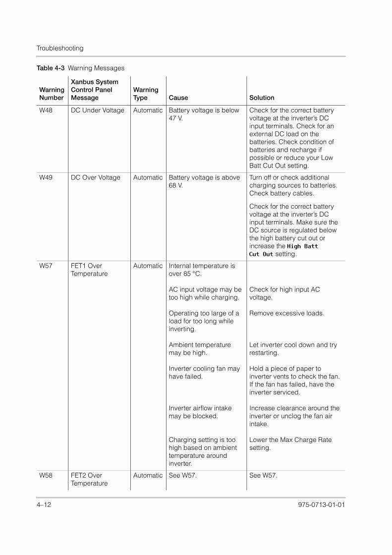
Troubleshooting
XW_Europe_Operation.book Page 12 Thursday, July 30, 2015 4:12 PM
W48 DC Under Voltage Automatic Battery voltage is below 47 V.
Check for the correct battery voltage at the inverter’s DC input terminals. Check for an external DC load on the batteries. Check condition of batteries and recharge if possible or reduce your Low Batt Cut Out setting.
W49 DC Over Voltage Automatic Battery voltage is above 68 V.
Turn off or check additional charging sources to batteries. Check battery cables.
Check for the correct battery voltage at the inverter’s DC input terminals. Make sure the DC source is regulated below the high battery cut out or increase the High Batt Cut Out setting.
W57 FET1 Over Temperature
Automatic Internal temperature is over 85 °C.
AC input voltage may be too high while charging.
Operating too large of a load for too long while inverting.
Ambient temperature may be high.
Inverter cooling fan may have failed.
Inverter airflow intake may be blocked.
Charging setting is too high based on ambient temperature around inverter.
Check for high input AC voltage.
Remove excessive loads.
Let inverter cool down and try restarting.
Hold a piece of paper to inverter vents to check the fan. If the fan has failed, have the inverter serviced.
Increase clearance around the inverter or unclog the fan air intake.
Lower the Max Charge Rate setting.
W58 FET2 Over Temperature
Automatic See W57. See W57.
Table 4-3 Warning Messages
Warning Number
Xanbus System Control Panel Message
Warning Type Cause Solution
4–12 975-0713-01-01

Faults and Warnings
XW_Europe_Operation.book Page 13 Thursday, July 30, 2015 4:12 PM
W63 AC Overload Automatic Excessive load on the AC output.
Check for loads above the inverter’s capacity. Turn off some loads if necessary.
W64 AC Overload Automatic See W63. See W63.
W68 Transformer Over Temperature
Automatic See W57. See W57.
W70 Synchronization Warning
Manual, AC input is not qualified
1. An AC input voltage phase is lost or out of the AC range in the three-phase.
2. AC input voltage phases are not synchronized with Conext 3-phase system.
1. Check the AC voltage presence of each phase at the AC input terminals for each Conext XW+.
2. Inspect the three-phase wiring to have the correct phase sequence: XW-Phase-A, XW-Phase-B, XW-Phase-C with the same AC input sequence to each unit.
W94 Remote Power Off Automatic The unit has been turned off with a Remote Power Off switch.
No action required. The unit stops inverting or charging immediately, and shuts down after five seconds. If the unit is configured as a master, it signals other network devices to also shut down.
W95 Equalize Abort Manual Equalization terminated abnormally because of interrupted AC input.
Wait until AC input (utility grid) returns to in-tolerance condition.
W96 Cannot Equalize Manual The selected battery type should not be equalized.
AC input is not qualified or the charge setting is not adequate.
Change battery type if your batteries should be equalized. Gel or AGM batteries should not be equalized.
Check for presence of AC. Make sure Charge and Equalize are enabled. Verify the Conext AGS trigger is set to Stop Float. If Stop V is enabled, then the voltage level should be above the Eqlz Voltage level.
W97 Battery temp sensor failure
Automatic Battery Temperature Sensor Shorted
Replace battery temperature sensor.
Table 4-3 Warning Messages
Warning Number
Xanbus System Control Panel Message
Warning Type Cause Solution
975-0713-01-01 4–13

Troubleshooting
XW_Europe_Operation.book Page 14 Thursday, July 30, 2015 4:12 PM
Fault Messages
When the Conext XW+ detects a fault condition, the fault is displayed on the Xanbus SCP. The Conext XW+ also turns on the Fault light on the Xanbus SCP and inverter information panel. A fault affects the operation of the unit. See “Fault Types” on page 4–14 for an explanation of the different fault types.
You can view the 20 most recent fault messages on the Xanbus SCP by selecting Fault Log from the Device Info menu in the Conext XW+ Setup Menu.
If several faults occur before you can acknowledge or clear them, they are displayed together on a fault list. This list contains messages from every Xanbus-enabled device, not just the Conext XW+. You can select a message and view its details from the fault list.
To view a message from a fault list:
1. On the list, use the up arrow or down arrow button to highlight the message you want to view.
2. Press Enter. The complete message appears.
After viewing the message, you can return to the fault list by pressing Exit or continue to the menu for the device that caused the fault by pressing Enter. Each time you return to the list after viewing a complete message, the viewed message is removed from the list.
If you have left the fault list, you can view faults at any time from the System Settings menu.
To view a fault list:
1. On the Select Device menu, highlight System Settings and press Enter.
2. On the System Settings menu, highlight View Fault List and press Enter.
Fault Types
There are three types of fault messages: automatic faults, manual faults, and escalating automatic faults. Table 4-4 describes how they differ in their behavior and how you can respond to them when they appear on the Xanbus SCP.
W500 Lost network connection
Automatic Lost network connection Check network cables.
W501 Inv/Chg is trying to fix a memory problem
Manual Non-volatile memory warning
Normal operation may return or may go to fault. Turn Conext XW+ off and on to resume normal operation.
Table 4-3 Warning Messages
Warning Number
Xanbus System Control Panel Message
Warning Type Cause Solution
4–14 975-0713-01-01

Faults and Warnings
XW_Europe_Operation.book Page 15 Thursday, July 30, 2015 4:12 PM
Inverter Operation After Faults
Conext XW+ operation changes when a fault occurs. How the operation changes depends on the operating state of the unit when the fault occurred—inverting, charging, grid or generator support, AC bypass, and so on—and on which fault has occurred.
Table 4-4 Fault Types and Behaviors
Fault type Behavior
Automatic faults Clear automatically if the fault condition that generated the message goes away. You can also acknowledge automatic faults without waiting for them to clear automatically. It is not possible to clear a fault if the cause of the fault is still present.
Manual faults Require you to clear them by:
• selecting Clear Faults on the Main Conext XW+ menu or on the menu for the Xanbus-enabled device that generated the fault (if the fault condition still exists, the fault message reappears)
• correcting the condition that caused the fault
Escalating automatic faults
Clear automatically if the fault condition goes away, same as an automatic fault.
However, if an escalating automatic fault occurs several times within a defined time period, the escalating automatic fault becomes a manual fault, requiring user intervention. For example, if an AC Overload fault occurs three times in five minutes, it will no longer clear itself and it will become a manual fault. You must identify the problem, correct the fault condition, and clear the fault.
Table 4-5 Inverter Operation After Faults
FaultsState when Faults Occur Action After Faults
F1, F2: AC Output Inverting Unit stops inverting and waits for nominal AC output voltage level or a manual clear from user.
F17 to F22: Relay Welded
Inverting Unit stops inverting and waits for user to clear fault. If qualified AC input is available, the unit is in AC bypass.
F23 to F40: Anti-Islanding
Grid Support (Peak Load Shaving or Selling)
Unit moves to AC bypass and waits for nominal grid conditions to return for a minimum of five minutes.
F41, F42: Aux power supply voltage
Unit has qualified AC input.
Unit shuts down and waits for nominal AC output voltage level, or a manual clear from user.
975-0713-01-01 4–15

Troubleshooting
XW_Europe_Operation.book Page 16 Thursday, July 30, 2015 4:12 PM
Table 4-6 provides descriptions of the fault messages and solutions. If you are unable to resolve the problem after referring to this table, contact your dealer or Customer Service.
F44: Battery Over Temp
F45: Capacitor Over Temp
Any state. If inverting, the unit shuts down and waits for the temperature to return to nominal value. If in any of the AC-interactive states (charging, peak load shaving, sell, or gen support), the unit goes into AC bypass mode until the temperature returns to the nominal value. If the unit is not in AC bypass, it shuts down until the temperature returns to nominal value. If qualified AC input is present, the unit is in AC bypass. After these faults clear, the unit returns to its previous operating state.
F47 to F49: DC Under Voltage and Over Voltage
Unit is inverting or has qualified AC input and is preparing to charge.
If inverting, the unit shuts down and waits for nominal voltage. If operating with a qualified AC source, the unit charges if charging is enabled or remains in AC bypass if charging is disabled.
F63 to F64: AC Overload
Inverting or Grid Support
Unit stops inverting and waits to qualify AC. Unit waits for user to manually clear fault.
Table 4-5 Inverter Operation After Faults
FaultsState when Faults Occur Action After Faults
Table 4-6 Fault Messages
Fault Number Message Fault Type Cause Solution
F1 AC Output Under Voltage
Escalating Auto Fault. Must occur 3 times in 2 minutes before becoming a manual fault.
AC under voltage shutdown at 210 V. The inverter has shut down to protect the loads.
Clear the fault and attempt restart. If problem persists, call customer service.
F2 AC Output Over Voltage
Escalating Auto Fault. Must occur 3 times in 30 seconds before becoming a manual fault.
AC overvoltage shutdown at 253 V. The inverter has shut down to protect the loads.
Clear the fault and attempt restart. If problem persists, call customer service.
F17 Relay(s) Welded Manual The AC1 Line transfer relay is bad or an AC source was wired directly to the AC output.
Disconnect the inverter’s output wiring. If error continues, have unit serviced.
4–16 975-0713-01-01

Faults and Warnings
XW_Europe_Operation.book Page 17 Thursday, July 30, 2015 4:12 PM
F19 Relay(s) Welded Manual AC2 Line transfer relay is bad or an AC source was wired directly to the AC output.
See F17.
F22 Relay(s) Welded Manual An unidentified Line transfer relay is bad or an AC source was wired directly to the AC output.
See F17.
F23 AI Over Frequency
Automatic Over-frequency anti-islanding, caught by the AC qualification limit.
No action required. The inverter stops selling and disconnects from the grid. When the fault clears, a five-minute timer begins counting down. The inverter does not sell again until grid voltage and frequency are within range for five minutes.
F24 AI Under Frequency
Automatic Under-frequency anti-islanding, caught by the AC qualification limit.
See F23.
F25 AI Over Frequency
Automatic Over-frequency anti-islanding.
See F23.
F26 AI Under Frequency
Automatic Under-frequency anti-islanding.
See F23.
F27 AI Over Voltage Automatic Over-voltage anti-islanding, fast disconnect, 270 Vac.
See F23.
F31 AI Over Voltage Automatic Over-voltage anti-islanding, slow disconnect, 253 V.
See F23.
F34 AI Under Voltage Automatic Under-voltage anti-islanding, slow disconnect, 198 V.
See F23.
F37 AI Under Voltage Automatic Under-voltage anti-islanding, fast disconnect, 138 Vac.
See F23.
F41 APS Under Voltage
Escalating Auto Fault. Must occur 3 times in 30 seconds before becoming a manual fault.
Auxiliary power supply under-voltage shutdown
Clear the fault and attempt restart. If problem persists, call customer service.
Table 4-6 Fault Messages
Fault Number Message Fault Type Cause Solution
975-0713-01-01 4–17

Troubleshooting
XW_Europe_Operation.book Page 18 Thursday, July 30, 2015 4:12 PM
F42 APS Over Voltage Escalating Auto Fault. Must occur 3 times in 30 seconds before becoming a manual fault.
Auxiliary power supply over-voltage shutdown
Clear the fault and attempt restart. If problem persists, call customer service.
F44 Battery Over Temperature
Automatic Battery over- temperature shutdown at 60 °C.
Clear the fault and attempt restart. Stop charging, check battery voltage and temperature. Check for excessive ambient temperature and adequate ventilation in the battery compartment.
Note: Shutdown temperature is above 60 °C. Recovery occurs at 50 °C where the XW will be enabled again.
F45 Capacitor Over Temperature
Automatic Capacitor over-temperature shutdown at 150 °C.
Clear the fault and attempt restart. Make sure that there is adequate ventilation around the Conext XW+. Reduce AC loads.
F46 Controller fault Manual Controller fault Service required.
F47 DC Under Voltage Automatic DC under-voltage shutdown (immediate) occurs if DC voltage is below 16 VDC (24 V system) or 32 VDC (48 V system). The fault clears and the inverter restarts when DC voltage reaches VLBCO+2 V (24 V system) and VLBCO+4 V (48 V system).
Check for the correct battery voltage at the inverter’s DC input terminals. Check for an external DC load on the batteries. Check condition of batteries and recharge if possible.
F48 DC Under Voltage Automatic DC under-voltage shutdown occurs if DC voltage is below LBCO voltage level.
See F47.
Table 4-6 Fault Messages
Fault Number Message Fault Type Cause Solution
4–18 975-0713-01-01

Faults and Warnings
XW_Europe_Operation.book Page 19 Thursday, July 30, 2015 4:12 PM
F49 DC Over Voltage Escalating Auto Fault.
DC over-voltage shutdown. Occurs if DC voltage is above 70 V. The fault can occur when batteries are disconnected at the DC breaker while the Conext XW+ is operating.
Clear the fault and attempt restart. Ensure battery voltage is below 58 VDC at Conext XW+ terminals. Check all other charging source outputs, battery cables. Ensure that batteries are connected, or that your DC source is regulated below your high battery cut out or increase your Hi Batt Cut Out setting.
F52 EEPROM Error Manual No action. Clear fault and resume operating or configuring the unit. If the fault persists, have the unit serviced.
F53 EEPROM Error Manual See F52.
F54 EEPROM Error Manual See F52.
F55 EEPROM Error Manual See F52.
F56 EEPROM Error Manual See F52.
Table 4-6 Fault Messages
Fault Number Message Fault Type Cause Solution
975-0713-01-01 4–19

Troubleshooting
XW_Europe_Operation.book Page 20 Thursday, July 30, 2015 4:12 PM
F57 FET1 Over Temperature Shutdown
Automatic Internal temperature is over 105 °C.
AC input voltage may be too high while charging.
Operating too large of a load for too long while inverting.
Ambient temperature may be high.
Inverter cooling fan may have failed.
Inverter airflow intake may be blocked.
Charging setting is too high based on ambient temperature around inverter.
Fault clears when temperature drops to 75 °C.
Check for high input AC voltage.
Remove excessive loads.
Let inverter cool down and try restarting.
Hold a piece of paper to inverter vents to check the fan. If the fan has failed, have the inverter serviced.
Increase clearance around the inverter or unclog the fan air intake.
Lower the Max Charge Rate setting.
F58 FET2 Over Temperature Shutdown
Automatic See F57. See F57.
F59 GOCFG process failed
Manual Auto-configuration process failed.
Retry the “Copy From” procedure, or configure the unit manually.
F63 AC Overload Escalating Auto Fault. Must occur 3 times in 5 minutes before becoming a manual fault.
Excessive load on the AC output.
Check for loads above the inverter’s capacity. Turn off some loads if necessary. To clear the fault:
Turn off the unit by holding the power button for 5 sec.
Disconnect the Conext XW+ from the battery bank for 20 sec.
Table 4-6 Fault Messages
Fault Number Message Fault Type Cause Solution
4–20 975-0713-01-01

Faults and Warnings
XW_Europe_Operation.book Page 21 Thursday, July 30, 2015 4:12 PM
F64 AC Overload Escalating Auto Fault. Must occur 3 times in 5 minutes before becoming a manual fault.
Excessive load on the AC output.
See F63
F66 System Configuration Fault
Automatic Multi-Unit Configuration settings are incorrect.
Make sure only one unit is configured as the master. For three-phase installations, make sure that only one unit on each phase is configured as the master. Make sure each unit has a unique Device Number and that Inverter Mode and Connections have been configured correctly. See “Three-Phase Configuration” on page 3–36 and “Connections Menu” on page 3–38.
F67 Watchdog Error Manual Service required.
F68 Transformer Over Temperature
Automatic The transformer temperature is over 140 °C.
The fault clears when the transformer temperature falls to 125 °C. Make sure that there is adequate ventilation around the Conext XW+. Reduce AC loads.
F69 External Sync Failed
Manual Check connections and cable on external AC sync port. In a single-inverter system, nothing must be plugged into the AC sync port. Clear fault and try again. If these steps fail, the unit requires service.
Table 4-6 Fault Messages
Fault Number Message Fault Type Cause Solution
975-0713-01-01 4–21

Troubleshooting
XW_Europe_Operation.book Page 22 Thursday, July 30, 2015 4:12 PM
F70 Check Phase Configuration
Automatic The unit cannot qualify its AC input because of an incorrect three-phase installation. For example, phase B and phase C are reversed, either through miswiring or incorrect Connections and Inverter Mode settings.
1. Make sure that only one unit on each phase is configured as the master. Make sure each unit has a unique Device Number and that Inverter Mode and Connections have been configured correctly. See “Three-Phase Configuration” on page 3–36 and “Connections Menu” on page 3–38.
2. Disconnect all units and make sure that the three-phase wiring is correct.
F71 Battery Discharge Over Current
Manual There is an excessive load on the Li-Ion battery. This fault applies only to Li-Ion batteries.
Change the default threshold of the max battery discharge current limit or reduce the load.
F72 External AC Contactor Malfunction
Manual The AC Contactor was not in the expected setting.
Check why the AC contactor has failed. Check for fusing of coil, wiring and connections. Verify that the AC contactor has power.
F500 Silicon Serial ID Failure
Manual Silicon Serial ID Failure Service required.
Table 4-6 Fault Messages
Fault Number Message Fault Type Cause Solution
4–22 975-0713-01-01

XW_Europe_Operation.book Page 1 Thursday, July 30, 2015 4:12 PM
A Specifications
Appendix A, “Specifications” provides the electrical and mechanical specifications for the Conext XW+ Inverter/Charger.

Specifications
XW_Europe_Operation.book Page 2 Thursday, July 30, 2015 4:12 PM
Electrical SpecificationsTable A-1 Conext XW+ Electrical Specifications
Conext XW+ 8548
Conext XW+ 7048
Continuous Output Power 6,800 W 5,500 W
Surge Rating (Overload for 1 minute) 12,000 W 9,500 W
Surge Rating (Overload for 5 minutes) 11,000 W 9,000 W
Surge Rating (Overload for 30 minutes) 8,500 W 7,000 W
Surge Current 53 Arms (60 s) 40 Arms (60 s)
Waveform True Sine Wave
Idle Consumption—invert mode, no load 28 W 26 W
Idle Consumption—search mode < 7 W
AC Output Voltage 230 Vac ±3%
AC Input Voltage Range (Bypass/Charge Mode) 165–280 V
AC Input Breaker 60 A double-pole
AC Input Frequency Range (Bypass/Charge Mode)
45–55 Hz (default)
40–68 Hz (allowable)
AC Output Continuous Current 29.5 A 24 A
AC Output Frequency 50.0 ±0.1 Hz
Total Harmonic Distortion < 5% at rated power
Automatic Transfer Relay Rating 60 A
Auxiliary Relay Output 0–12 VDC, maximum 250 mA DC
Peak Efficiency 95.8% 95.8%
DC Input Voltage (Nominal) 48 VDC 48 VDC
DC Input Voltage Range 40–64 VDC 40–64 VDC
Maximum DC Input Current 180 A 150 A
Continuous Charge Rate at Nominal Voltage 140 A 110 A
Power Factor Corrected Charging PF (0.98)
A–2 975-0713-01-01

Electrical Specifications
XW_Europe_Operation.book Page 3 Thursday, July 30, 2015 4:12 PM
Conext XW+ Overload Capability
Loads connected to the inverter are seldom constant, and large loads are often operated for short periods. To accommodate larger loads, the Conext XW+ can temporarily exceed its continuous output power rating. The graphs below illustrate approximate operation time versus load.
Inverter operation time during overload is limited by both inverter internal temperature protection and by the product of AC output current and elapsed time.
Figure A-1 Conext XW+ AC Overload Capability
100
101
102
103
104
105
106
4500
5500
7000
9000
9500
Time in Seconds
Line
-Neu
tral
(23
0 V
) Lo
ad [W
]
Conext XW+ 7048 IEC L-N Inverter Surge Profile
5 Minutes
30 Minutes
Surge Power Versus Time
6800
8500
11000
12500
Line
-Neu
tral
(23
0 V
) Lo
ad [W
]
Conext XW+ 8548 IEC L-N Inverter Surge Profile
5 Minutes
30 Minutes
Surge Power Versus Time
100
101
102
103
104
105
106
Time in Seconds
975-0713-01-01 A–3

Specifications
XW_Europe_Operation.book Page 4 Thursday, July 30, 2015 4:12 PM
Output Power Versus Ambient Temperature
When the internal temperature of the Conext XW+ exceeds a preset limit, it begins to limit output power automatically to stop maximum internal temperatures from being exceeded.
Conext XW+ Efficiency
Inverting Efficiency (Typical)
Figure A-2 Output Power Versus Ambient Temperature
Figure A-3 Inverting Efficiency (Typical)
0
1000
2000
3000
4000
5000
6000
7000
8000
-25 -15 -5 5 15 25 35 45 55 65 75
Out
put
Pow
er (
Wat
ts)
Ambient Temperature (°C)
Conext XW+ Power Derating
75%
80%
85%
90%
95%
100%
0 500 1000 1500 2000 2500 3000 3500 4000 4500 5000 5500 6000 6500 7000
XW+ 7048
XW+ 8548
Effi
cien
cy (
%)
Output Power (Watts)
A–4 975-0713-01-01

Electrical Specifications
XW_Europe_Operation.book Page 5 Thursday, July 30, 2015 4:12 PM
Charging Efficiency (Typical)
Charging Efficiency Power Factor
Figure A-4 Charging Efficiency (Typical)
Figure A-5 Charging Efficiency Power Factor
75%
80%
85%
90%
95%
100%
0 10 20 30 40 50 60 70 80 90 100 110 120 130 140
Effi
cien
cy (
%)
Charge Current (Amps)
75%
80%
85%
90%
95%
100%
0 10 20 30 40 50 60 70 80 90 100 110 120 130 140 150 160 170 180
Pow
er F
acto
r (%
)
Charge Current (Amps)
975-0713-01-01 A–5
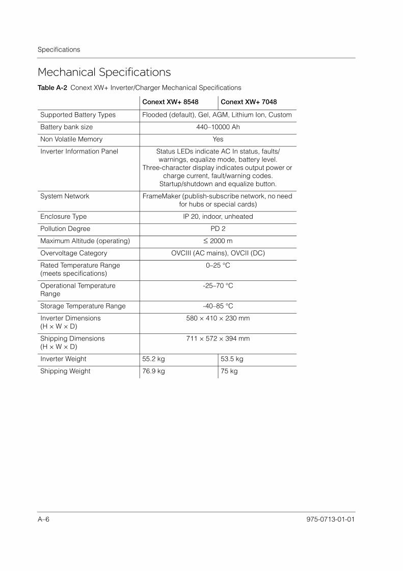
Specifications
XW_Europe_Operation.book Page 6 Thursday, July 30, 2015 4:12 PM
Mechanical SpecificationsTable A-2 Conext XW+ Inverter/Charger Mechanical Specifications
Conext XW+ 8548 Conext XW+ 7048
Supported Battery Types Flooded (default), Gel, AGM, Lithium Ion, Custom
Battery bank size 440–10000 Ah
Non Volatile Memory Yes
Inverter Information Panel Status LEDs indicate AC In status, faults/warnings, equalize mode, battery level.
Three-character display indicates output power or charge current, fault/warning codes.
Startup/shutdown and equalize button.
System Network FrameMaker (publish-subscribe network, no need for hubs or special cards)
Enclosure Type IP 20, indoor, unheated
Pollution Degree PD 2
Maximum Altitude (operating) 2000 m
Overvoltage Category OVCIII (AC mains), OVCII (DC)
Rated Temperature Range (meets specifications)
0–25 °C
Operational Temperature Range
-25–70 °C
Storage Temperature Range -40–85 °C
Inverter Dimensions (H × W × D)
580 × 410 × 230 mm
Shipping Dimensions (H × W × D)
711 × 572 × 394 mm
Inverter Weight 55.2 kg 53.5 kg
Shipping Weight 76.9 kg 75 kg
A–6 975-0713-01-01

Mechanical Specifications
XW_Europe_Operation.book Page 7 Thursday, July 30, 2015 4:12 PM
Figure A-6 Conext XW+ Block Diagram
L-GridN
L-GenN
L-Load
NEMIF
ilter
+12V
RTNRPO INOU
T
XBus
XBus
Sync
Sync
BTS
DC+
DC-
EMIF
ilter
AC
Filte
r
PE
Control & MonitoringInternal Transfer Relay
Power Bridge
PowerTransformer
975-0713-01-01 A–7

Specifications
XW_Europe_Operation.book Page 8 Thursday, July 30, 2015 4:12 PM
Accessories
Regulatory ApprovalsCE marked and complies with the following:
Low Voltage Directive 2006/95/EC, per:
• EN50178 “Electronic Equipment for Use in Power Installations”.
EMC Directive 2004/108/EC, per:
• EN61000-6-3 “Emission Standard for Residential, Commercial, and Light-Industrial Environments”
• EN61000-6-1 “Immunity for Residential, Commercial, and Light-Industrial Environments”
RCM marked and complies with the following:
• AS 4777.2: 2005 “Inverter requirements”
• AS 4777.3: 2005 “Grid protection requirements”
• IEC 62109-1: 2010 “General Requirements”
• IEC 62109-2: 2011 “Particular Requirements for Inverters”
• AS/NZS 60335.2.29:2004 + A1&A2 “Particular Requirements for Battery Chargers”
Table A-3 Conext XW+ Accessories
Accessory Part Number
Conext XW+ Power Distribution Panel 865-1015-01
Conext XW+ Power Distribution Panel (Without AC Breakers)
865-1014-01
Conext XW+ Conduit Box 865-1025-01
Conext XW+ Connection Kit for INV2 INV3 PDP 865-1020-02
Xanbus System Control Panel 865-1050-01
Conext Automatic Generator Start 865-1060-01
Conext MPPT 60 150 Solar Charge Controller 865-1030-1
Conext MPPT 80 600 Solar Charge Controller 865-1032
Conext ComBox 865-1058
Conext Battery Monitor 865-1080-01
Conext XW+ PDP 120/240V 60A Breaker Kit 865-1215-01
Conext XW+ PDP 3-Phase 60A Breaker Kit 865-1315-01
A–8 975-0713-01-01

XW_Europe_Operation.book Page 1 Thursday, July 30, 2015 4:12 PM
B Default Settings
Appendix B contains the default configuration settings and ranges for the Conext XW+ Inverter/Charger. Configuration settings can be viewed and changed using the Xanbus System Control Panel.

Default Settings
XW_Europe_Operation.book Page 2 Thursday, July 30, 2015 4:12 PM
Default Settings and Ranges
Figure B-1 shows how the Conext XW+ configuration menus are organized in the Xanbus System Control Panel.
Figure B-1 Configuration Menu Map (Advanced)
XW+ 8548 00:AC
XW+ 8548 00:Inv
XW+ 8548 00: Multi
XW+ 8548 00:Gen
XW+ 8548 00: Aux
XW+ 8548 00:Grid
XW+ 8548 00:Chg
Custom Settings
XW+ 8548 00: Adv
Connections
[46V][10s]
[2.0V][70V][50W][2s]
[Enabled][64.0V][57.6V][57.6V][54.0V]
[108mV/C]
[Flooded]
[440Ah][100%]
[2-Stage][Warm][50V]
[180min][12:00AM][12:00AM]
[AC1][56A]
[202V][260V][45Hz][55Hz][56A][202V][264V][45Hz][55Hz]
[53V][Disabled]
[27A][Disabled]
[44A][12:00AM][12:00AM][12:00AM][12:00AM]
[ManualOff][ActHi]
[LowBattV][44V]
[1sec][48V]
[1sec]
[XW+8548][00]
[1PhMaster]
XW+ 8548 00:Adv Features
[Disabled][Disabled][Disabled][Enabled]
[Disabled][Enabled]
[Disabled]
[HouseBatt1][ACLoad1][Grid1][Gen1]
[Disabled][44A]
[XW+ 8548 01]
LithiumIon
[EXT_BMS][14.4V][140A]
[14.4V][140A]
[14.4V][140A][150%][10s]
B–2 975-0713-01-01

Default Settings and Ranges
XW_Europe_Operation.book Page 3 Thursday, July 30, 2015 4:12 PM
Inverter Menu
Charger Menu
Item Default Setting Range Step Size
Low Batt Cut Out 46 V 40–48 V 0.1
LBCO Hysteresis 2 V 0-10 V 0.1
LBCO Delay 10s 0–600s 1
High Batt Cut Out 70 V 58–70 V 0.1
Search Watts 50 W 25–255 W 5
Search Delay 2s 1–25s 1
Item Default Setting Range Step Size
Batt Type Flooded Flooded, Gel, AGM, Customa
a.When Custom battery selected, two sub-menus appear: Custom Settings andLithiumIon
n/a
Batt Capacity 440 Ah 0–10000 Ahb
b.Setting the battery capacity to 0 will reset the charging current to its default val-ues. Zero Ah battery capacity implies there is no absorption exit current criteriaand absorption only exits when the absorption timer (default 3 hrs, range 1 min-8 hr) expires.
1
Max Chg Rate 100% 5–100% 1
Charge Cycle 2-Stage 2-Stage, 3-Stage n/a
Default Batt Temp Warm Cold, Warm, Hot n/a
ReCharge Volts 50 V 40.0–54.0 V 0.1
Absorb Time 180 min 1–480 min 1
Chg Block Start 12:00 AM 12:00 AM–11:59 PM,00:00–23:59
1
Chg Block Stop 12:00 AM 12:00 AM–11:59 PM,00:00–23:59
1
975-0713-01-01 B–3

Default Settings
XW_Europe_Operation.book Page 4 Thursday, July 30, 2015 4:12 PM
Custom Settings Submenu
LithiumIon Submenu
AC Menu
Item Default Setting Range Step Size
Eqlz Support Enabled Enabled, Disabled n/a
Eqlz Voltage 64.0 V 54.0–64.0 V 0.1
Bulk Voltagea
a.Custom battery default settings are based on the Flooded battery default set-tings. The Gel and AGM default settings are provided here for reference only.
57.6 V56.8 V (Gel)57.2 V (AGM)
54.2–64.0 V 0.1
Absorb Voltagea 57.6 V56.8 V (Gel)57.2 V (AGM)
40.0–64.0 V 0.1
Float Voltagea 54.0 V55.2 V (Gel)53.6 V (AGM)
50.0–64.0 V 0.1
Batt Temp Compa 108 mV/C (Flooded, Gel)
84 mV/C (AGM)
0–180 mV/C 1
Item Default Setting Range Step Size
Control EXT_BMS EXT_BMS, 3stage, 2stage NoFloat
n/a
Bulk Voltage 57.6 V 54.2.0–64.0 V 0.1
Max Bulk Current 140 A 10-140 A 1
Abs Voltage 57.6 V 40.0–64.0 V 0.1
Max Abs Current 140 A 10-140 A 1
Float Voltage 54.0 V 50.0–64.0 V 0.1
Max Float Current 140 A 1-140 A 1
DisChglmax 150% 20-500% 1
DisChglmax Timer 10 sec 0-300 sec 1
Item Default Setting Range Step Size
AC Priority AC1 AC1, AC2 n/a
AC1 Breaker 56 A 3–60 A 1
AC1 Lo Volt 202 V 156–220 V 1
AC1 Hi Volt 260 V 240–280 V 1
AC1 Lo Freq 45 Hz 40–48 Hz 1
AC1 Hi Freq 55 Hz 52–68 Hz 1
AC2 Breaker 56 A 3–60 A 1
AC2 Lo Volt 202 V 156–220 V 1
AC2 Hi Volt 264 V 240–280 V 1
B–4 975-0713-01-01

Default Settings and Ranges
XW_Europe_Operation.book Page 5 Thursday, July 30, 2015 4:12 PM
Grid Support Menu
Gen Support Menu
Aux Menu
AC2 Lo Freq 45 Hz 40–48 Hz 1
AC2 Hi Freq 55 Hz 52–68 Hz 1
Item Default Range Step Size
Grid Supp Volts 53.0 Va
a.The setting for Grid Supp Volts must be greater or equal to LBCO+2 V. For example, ifLBCO is 44 V then the minimum Grid Supp Volts is 46 V.
42.0–70.0 V 0.1
Sell Disabled Disabled, Enabled n/a
Max Sell Ampsb
b.This setting is restricted to the selected external AC1 breaker size.
27 A (XW+ 8548),20 A (XW+ 7048)
0–27 A (XW+ 8548),0–20 A (XW+ 7048)
1
Load Shave Disabled Disabled, Enabled n/a
Load Shave Amps 44 A 0–48 A 1
Load Shave Startc
c.When Load Shaving is enabled, if Load Shave Start and Load Shave Stop are set to thesame time, the Conext load shaves continuously.
12:00 AM 12:00 AM–11:59 PM,00:00–23:59
1
Load Shave Stop 12:00 AM 12:00 AM–11:59 PM,00:00–23:59
1
Sell Block Start 12:00 AM 12:00 AM–11:59 PM,00:00–23:59
1
Sell Block Stop 12:00 AM 12:00 AM–11:59 PM,00:00–23:59
1
Setting Default Range Step Size
GenSupp Mode Disabled Enabled, Disabled n/a
GenSupp Amps 44 A 3–48 A 1
Item Default RangeStep Size
Manual Aux ManualOff ManualOn, ManualOff, Automatic
n/a
Active Lvl ActiveHigh ActiveHigh, ActiveLow n/a
Trigger Srca LowBattV LowBattV, HighBattV, LowBattTemp, HighBattTemp, Fault
n/a
Trigger Level—LowBattVb 46.0 VDC 20.0–58.0 VDC 0.1
Clear Level—LowBattV 48.0 VDC 20.0–58.0 VDC 0.1
Item Default Setting Range Step Size
975-0713-01-01 B–5
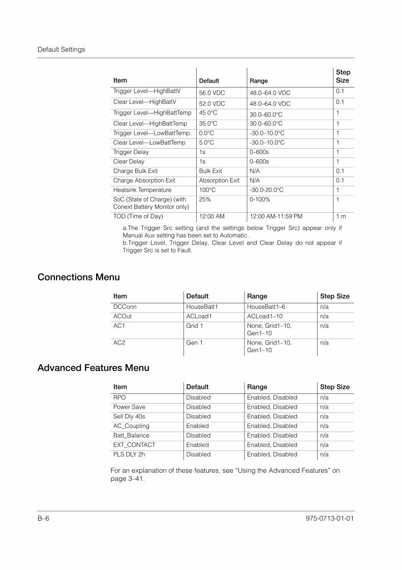
Default Settings
XW_Europe_Operation.book Page 6 Thursday, July 30, 2015 4:12 PM
Connections Menu
Advanced Features Menu
For an explanation of these features, see “Using the Advanced Features” on page 3–41.
Trigger Level—HighBattV 56.0 VDC 48.0–64.0 VDC 0.1
Clear Level—HighBattV 52.0 VDC 48.0–64.0 VDC 0.1
Trigger Level—HighBattTemp 45.0°C 30.0–60.0°C 1
Clear Level—HighBattTemp 35.0°C 30.0–60.0°C 1
Trigger Level—LowBattTemp 0.0°C -30.0–10.0°C 1
Clear Level—LowBattTemp 5.0°C -30.0–10.0°C 1
Trigger Delay 1s 0–600s 1
Clear Delay 1s 0–600s 1
Charge Bulk Exit Bulk Exit N/A 0.1
Charge Absorption Exit Absorption Exit N/A 0.1
Heatsink Temperature 100°C -30.0-20.0°C 1
SoC (State of Charge) (with Conext Battery Monitor only)
25% 0-100% 1
TOD (Time of Day) 12:00 AM 12:00 AM-11:59 PM 1 m
a.The Trigger Src setting (and the settings below Trigger Src) appear only ifManual Aux setting has been set to Automatic.b.Trigger Level, Trigger Delay, Clear Level and Clear Delay do not appear ifTrigger Src is set to Fault.
Item Default Range Step Size
DCConn HouseBatt1 HouseBatt1–6 n/a
ACOut ACLoad1 ACLoad1–10 n/a
AC1 Grid 1 None, Grid1–10, Gen1–10
n/a
AC2 Gen 1 None, Grid1–10, Gen1–10
n/a
Item Default Range Step Size
RPO Disabled Enabled, Disabled n/a
Power Save Disabled Enabled, Disabled n/a
Sell Dly 40s Disabled Enabled, Disabled n/a
AC_Coupling Enabled Enabled, Disabled n/a
Batt_Balance Disabled Enabled, Disabled n/a
EXT_CONTACT Enabled Enabled, Disabled n/a
PLS DLY 2h Disabled Enabled, Disabled n/a
Item Default RangeStep Size
B–6 975-0713-01-01

Index
XW_Europe_Operation.book Page 1 Thursday, July 30, 2015 4:12 PM
Numerics2-stage charge mode 143-stage charge mode 11
Aabsorption charging stage 12AC Coupling 9AC settings menu
default settings 4description 21
accessories 8advanced features menu 41Advanced menu 4automatic faults 15automatic generator start 8auxiliary output menu
default settings 5description 31
BBattery Charger Functions 11battery level LEDs 7battery type 10Bidirectional Theory of Operation 3bulk charging stage 12
Ccharger block 10, 26charger settings menu
default settings 3description 9
charger status LED 4charging cycle diagram 11Conext SCP
device setup menus 12features 11, 9select device menu 12system status screen 13
Conext XW+ Inverter/Charger home screen 13connections menu
default settings 6description 38
Copying Settings From Another Unit 39custom battery menu 19
Ddefault settings, restoring 40device home screen 13Distinguishing Features 2
Down arrow button 9
Eelectrical specifications 2energy management features 24Enter button 9equalize button and LED 5equalize mode 15escalating automatic faults 15Event LED (Inverter Information Panel) 5Exit button 9
Ffault types 15fault/warning LED (System Control Panel) 9faults and warnings 10features 2float charging stage 13
GGen (AC2) LED 2generator support 14generator support menu
default settings 5description 29
Grid (AC1) LED 2grid support 15, 24grid support settings menu
default settings 5description 22
Hhome screen 13
IInverter Information Panel 10inverter settings menu
default settings 3description 7
inverter status LED 3
KK1 and K2 relay 10keypress for system standby mode 10
LLEDs 5load shave 15, 23, 27
IX–1
Index
XW_Europe_Operation.book Page 2 Thursday, July 30, 2015 4:12 PM
Mmanual faults 15mechanical specifications 6menu map 6, 2meters screen 15multi-stage charging process 11Multi-unit Operation 8
Nno float charging stage 14
Ppassthru 15peak load shaving 27Performance Highlights 2Power Save 41, 6
Qqualifying AC 14
Rrecharge volts 10restore default settings 40RPO 41, 6
SSchneider Electric website ivsearch mode 15, 2, 7, 8self-consumption 28sell mode 15, 23specifications
electrical 2mechanical 6
standby 15standby button 9, 10startup/shutdown button 6state of charge LEDs 7System Control Panel. See Conext SCPsystem home screen 11system standby mode 10system status screen 13
TThree-Phase Configuration 36three-stage charge mode 11Time-of-Use (TOU) metering 27troubleshooting
battery charger 7fault messages 14general guidelines 2inverter 4motor loads 3problem loads 3
resistive loads 3warning messages 10
two-stage charge mode 14
UUp arrow button 9
Wwarning
automatic 11manual 11
IX–2 975-0713-01-01

XW_Europe_Operation.book Page 3 Thursday, July 30, 2015 4:12 PM

XW_Europe_Operation.book Page 4 Thursday, July 30, 2015 4:12 PM
975-0713-01-01 Rev B
Schneider Electric
solar.schneider-electric.com
As standards, specifications, and designs change from time to time, please ask for confirmation of the information given in this publication.
© 2015 Schneider Electric. All rights reserved.
975-0713-01-01 Rev BPrinted in China


