58
Empowered by Innovation Conference Bridge Manual P/N 0893215 Rev 1, September 2006 Printed in U.S.A. 5.99 Technical Support Web Site: http://ws1.necii.com (registration is required)

Empowered by Innovation
Conference Bridge Manual
P/N 0893215
Rev 1, September 2006Printed in U.S.A.
5.99
Technical Support Web Site: http://ws1.necii.com (registration is required)

This manual has been developed by NEC Unified Solutions, Inc. It is intended for the use of its customers andservice personnel, and should be read in its entirety before attempting to install or program the system. Anycomments or suggestions for improving this manual would be appreciated. Forward your remarks to:
NEC Unified Solutions, Inc.
4 Forest ParkwayShelton, CT 06484
necunifiedsolutions.com
Nothing contained in this manual shall be deemed to be, and this manual does not constitute, a warranty of, orrepresentation with respect to, any of the equipment covered. This manual is subject to change without notice andNEC Unified Solutions, Inc. has no obligation to provide any updates or corrections to this manual. Further, NECUnified Solutions, Inc. also reserves the right, without prior notice, to make changes in equipment design orcomponents as it deems appropriate. No representation is made that this manual is complete or accurate in allrespects and NEC Unified Solutions, Inc. shall not be liable for any errors or omissions. In no event shall NEC UnifiedSolutions, Inc. be liable for any incidental or consequential damages in connection with the use of this manual. Thisdocument contains proprietary information that is protected by copyright. All rights are reserved. No part of thisdocument may be photocopied or reproduced without prior written consent of NEC Unified Solutions, Inc.
©2006 by NEC Unified Solutions, Inc. All Rights Reserved.Printed in U.S.A.
Microsoft and Windows are registered trademarks of Microsoft Corporation.

Table of Contents
Aspire Conference Bridge Manual
◆
Table of Contents- 1
Chapter 1 : Aspire Conference Bridge PCB . . . . . . . . . . . . . . . . . . . . . . . . . . 1
PCB Description. . . . . . . . . . . . . . . . . . . . . . . . . . . . . . . . . . . . . . . . . . . . . . . . . . . . . . . . . .1
DESCRIPTION . . . . . . . . . . . . . . . . . . . . . . . . . . . . . . . . . . . . . . . . . . . . . . . . . . . . . . . . . . . . . . . . . . . 1
INDICATORS, BUTTONS AND CONNECTORS . . . . . . . . . . . . . . . . . . . . . . . . . . . . . . . . . . . . . . . . . 2
LED Indicators . . . . . . . . . . . . . . . . . . . . . . . . . . . . . . . . . . . . . . . . . . . . . . . . . . . . . . . 3PCB Buttons . . . . . . . . . . . . . . . . . . . . . . . . . . . . . . . . . . . . . . . . . . . . . . . . . . . . . . . . . 3Connectors . . . . . . . . . . . . . . . . . . . . . . . . . . . . . . . . . . . . . . . . . . . . . . . . . . . . . . . . . . 4Environmental Conditions . . . . . . . . . . . . . . . . . . . . . . . . . . . . . . . . . . . . . . . . . . . . . . 4
Chapter 2 : Aspire Conference Bridge PCB Setup . . . . . . . . . . . . . . . . . . . . . 5
INSTALLING THE 16CNFU PCB . . . . . . . . . . . . . . . . . . . . . . . . . . . . . . . . . . . . . . . . . . . . .5
System Requirements . . . . . . . . . . . . . . . . . . . . . . . . . . . . . . . . . . . . . . . . . . . . . . . . . . . . . . . . . . . . . 5
Installation Precautions . . . . . . . . . . . . . . . . . . . . . . . . . . . . . . . . . . . . . . . . . . . . . . . . . . . . . . . . . . . 5
Aspire System Programming . . . . . . . . . . . . . . . . . . . . . . . . . . . . . . . . . . . . . . . . . . . . . . . . . . . . . . . 6
Chapter 3 : Aspire Conference Bridge PCB Configuration . . . . . . . . . . . . . . 7
16CNFU PCB CONFIGURATION. . . . . . . . . . . . . . . . . . . . . . . . . . . . . . . . . . . . . . . . . . . .7
Configuring the 16CNFU PCB . . . . . . . . . . . . . . . . . . . . . . . . . . . . . . . . . . . . . . . . . . . . . . . . . . . . . . . 7
Configuring the PC . . . . . . . . . . . . . . . . . . . . . . . . . . . . . . . . . . . . . . . . . . . . . . . . . . . . . . . . . . . . . . . . 8
Chapter 4 : Aspire Conference Bridge PCB Web Manager . . . . . . . . . . . . . 13
Using the Web Manager . . . . . . . . . . . . . . . . . . . . . . . . . . . . . . . . . . . . . . . . . . . . . . . . . .13
LOGGING INTO ASPIRE CONFERENCE BRIDGE PCB . . . . . . . . . . . . . . . . . . . . . . . . . . . . . . . . . . 13
Authentication Levels . . . . . . . . . . . . . . . . . . . . . . . . . . . . . . . . . . . . . . . . . . . . . . . . 14
MAIN PAGE . . . . . . . . . . . . . . . . . . . . . . . . . . . . . . . . . . . . . . . . . . . . . . . . . . . . . . . . . . . . . . . . . . . . 15
Navigation Side Bar . . . . . . . . . . . . . . . . . . . . . . . . . . . . . . . . . . . . . . . . . . . . . . . . . . 16Status Window . . . . . . . . . . . . . . . . . . . . . . . . . . . . . . . . . . . . . . . . . . . . . . . . . . . . . . 16Operations Window . . . . . . . . . . . . . . . . . . . . . . . . . . . . . . . . . . . . . . . . . . . . . . . . . . 16
SETUP NEW CONFERENCE . . . . . . . . . . . . . . . . . . . . . . . . . . . . . . . . . . . . . . . . . . . . . . . . . . . . . . . 17
CONFERENCE MANAGER . . . . . . . . . . . . . . . . . . . . . . . . . . . . . . . . . . . . . . . . . . . . . . . . . . . . . . . . 22
Conference Details . . . . . . . . . . . . . . . . . . . . . . . . . . . . . . . . . . . . . . . . . . . . . . . . . . . 23Edit Conference . . . . . . . . . . . . . . . . . . . . . . . . . . . . . . . . . . . . . . . . . . . . . . . . . . . . . 24Delete Conference . . . . . . . . . . . . . . . . . . . . . . . . . . . . . . . . . . . . . . . . . . . . . . . . . . . 25
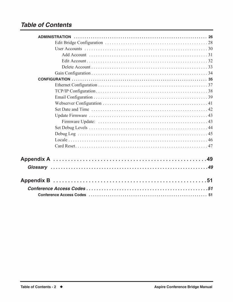
Table of Contents
Table of Contents - 2
◆
Aspire Conference Bridge Manual
ADMINISTRATION . . . . . . . . . . . . . . . . . . . . . . . . . . . . . . . . . . . . . . . . . . . . . . . . . . . . . . . . . . . . . . . 26
Edit Bridge Configuration . . . . . . . . . . . . . . . . . . . . . . . . . . . . . . . . . . . . . . . . . . . . . 28User Accounts . . . . . . . . . . . . . . . . . . . . . . . . . . . . . . . . . . . . . . . . . . . . . . . . . . . . . . 30
Add Account . . . . . . . . . . . . . . . . . . . . . . . . . . . . . . . . . . . . . . . . . . . . . . . . . . . . 31Edit Account . . . . . . . . . . . . . . . . . . . . . . . . . . . . . . . . . . . . . . . . . . . . . . . . . . . . . 32Delete Account . . . . . . . . . . . . . . . . . . . . . . . . . . . . . . . . . . . . . . . . . . . . . . . . . . . 33
Gain Configuration . . . . . . . . . . . . . . . . . . . . . . . . . . . . . . . . . . . . . . . . . . . . . . . . . . . 34
CONFIGURATION . . . . . . . . . . . . . . . . . . . . . . . . . . . . . . . . . . . . . . . . . . . . . . . . . . . . . . . . . . . . . . . . 35
Ethernet Configuration . . . . . . . . . . . . . . . . . . . . . . . . . . . . . . . . . . . . . . . . . . . . . . . . 37TCP/IP Configuration . . . . . . . . . . . . . . . . . . . . . . . . . . . . . . . . . . . . . . . . . . . . . . . . . 38Email Configuration . . . . . . . . . . . . . . . . . . . . . . . . . . . . . . . . . . . . . . . . . . . . . . . . . . 39Webserver Configuration . . . . . . . . . . . . . . . . . . . . . . . . . . . . . . . . . . . . . . . . . . . . . . 41Set Date and Time . . . . . . . . . . . . . . . . . . . . . . . . . . . . . . . . . . . . . . . . . . . . . . . . . . . 42Update Firmware . . . . . . . . . . . . . . . . . . . . . . . . . . . . . . . . . . . . . . . . . . . . . . . . . . . . 43
Firmware Update: . . . . . . . . . . . . . . . . . . . . . . . . . . . . . . . . . . . . . . . . . . . . . . . . 43Set Debug Levels . . . . . . . . . . . . . . . . . . . . . . . . . . . . . . . . . . . . . . . . . . . . . . . . . . . . 44Debug Log . . . . . . . . . . . . . . . . . . . . . . . . . . . . . . . . . . . . . . . . . . . . . . . . . . . . . . . . . 45Locale . . . . . . . . . . . . . . . . . . . . . . . . . . . . . . . . . . . . . . . . . . . . . . . . . . . . . . . . . . . . . 46Card Reset. . . . . . . . . . . . . . . . . . . . . . . . . . . . . . . . . . . . . . . . . . . . . . . . . . . . . . . . . . 47
Appendix A . . . . . . . . . . . . . . . . . . . . . . . . . . . . . . . . . . . . . . . . . . . . . . . . . . . . 49
Glossary . . . . . . . . . . . . . . . . . . . . . . . . . . . . . . . . . . . . . . . . . . . . . . . . . . . . . . . . . . . . . .49
Appendix B . . . . . . . . . . . . . . . . . . . . . . . . . . . . . . . . . . . . . . . . . . . . . . . . . . . . 51
Conference Access Codes . . . . . . . . . . . . . . . . . . . . . . . . . . . . . . . . . . . . . . . . . . . . . . . .51
Conference Access Codes . . . . . . . . . . . . . . . . . . . . . . . . . . . . . . . . . . . . . . . . . . . . . . . . . . . . . . . . 51

Chapter 1 : Aspire Conference Bridge PCB
PCB Description
Aspire Conference Bridge Manual
◆
1
Chapter 1 : Aspire Conference Bridge PCB
PCB Description
Chapter 1
DESCRIPTION
The 16CNFU PCB (P/N 0891069) is a conference bridge system designed for the Aspire M/L/XL system. The PCB is installed in the telephone system and allows up to 16 parties to take part in a conference call. The participants dial a pre-assigned phone number at the determined time, optionally enter a password, and are prompted to speak their name which will be announced to the other conference participants. The 16CNFU PCB functionalities include:
●
Password protection is provided for each conference.
●
Applicable voice messages and announcements (e.g., entry, password request, exit) are available.
●
E-mail notiÞcation, when enabled, requires the organizer to enter the E-mail address of each participant to be sent notiÞcation of a pending conference. This option is selectable when setting up new conferences.
The 16CNFU E-mail conÞguration supports SMTP mail server ONLY.
●
Host Required, when enabled, requires the host/organizer to be logged into the conference before any other participant can enter. This option is selectable when setting up new conferences.
●
Admission Control, when enabled, requires the organizer to dial a digit allowing each participant to enter the conference. This option is predeÞned access code.
●
One customer greeting can be recorded for each 16CNFU PCB. PredeÞned password is necessary to record personal greetings.
●
Password protection option for each conference.
●
Remote conference programming with conference scheduler (via a Web User Interface).
●
Programmable gain adjustments.
●
Support for DTMF detection for manual setup options (Telephone User Interface).
●
HTTP Interface for conference schedule management and conference PCB administration.
The maximum number of 16CNFU PCBs which can be installed depends on the type of NTCPU and PAL chip used in the Aspire system.
Note that when multiple 16CNFU PCBs are installed, the users in a conference call must all be on the same 16CNFU PCB. A call cannot span multiple PCBs.
Currently, when using PCPro or WebPro, when reviewing the system conÞguration for the cards, the 16CNFU PCB will be displayed as an ESIU PCB.
NTCPU-A with Basic PAL Chip
NTCPU-A with Feature Upgrade
PAL Chip(Software 6.xx+)
NTCPU-B
16CNFU PCB 4 8 16

Chapter 1 : Aspire Conference Bridge PCB
PCB Description
2
◆
Aspire Conference Bridge Manual
INDICATORS, BUTTONS AND CONNECTORS
Refer to
Figure 1: 16CNFU PCB
for LED and switch locations.
Figure 1: 16CNFU PCB
Reset Button (SW3)
CompactFlash Card Slot
PCB Status LEDs(on back of PCB)
Busy LED
Channel 1-8 LEDs
Factory Reset
Ethernet Connector
Button (SW1)
(on back of PCB)
Chapter 1 : Aspire Conference Bridge PCB
PCB Description
Aspire Conference Bridge Manual
◆
3
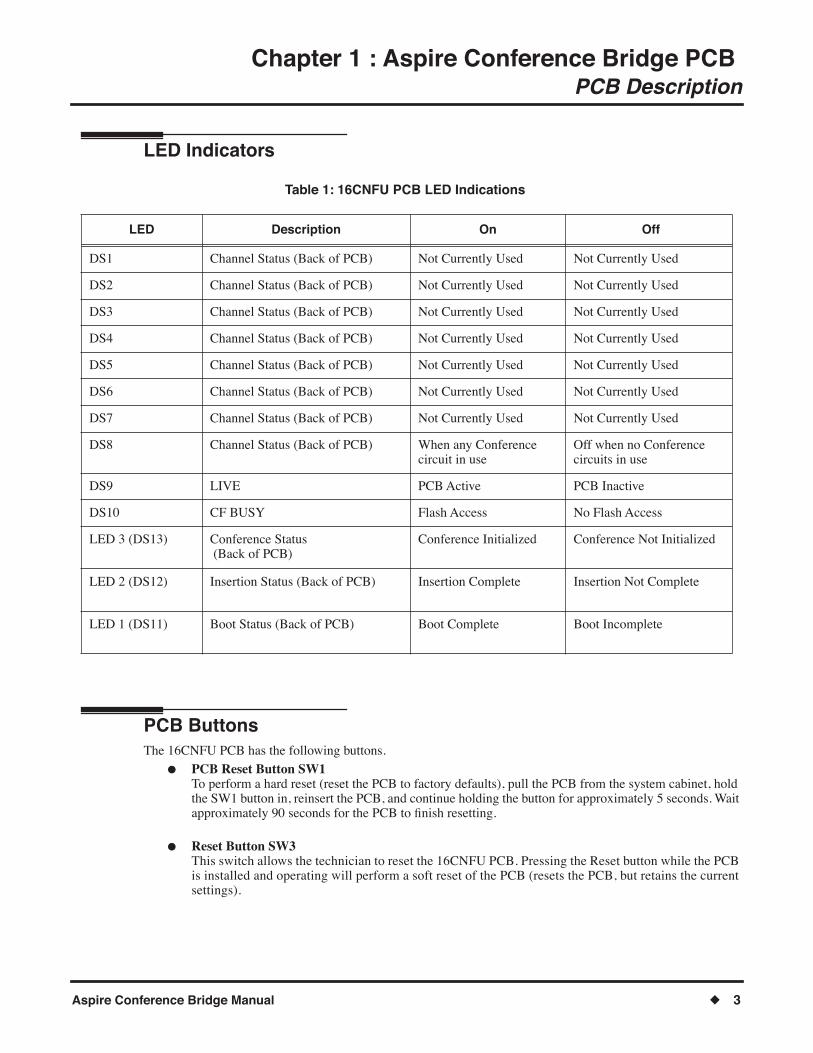
LED Indicators
Table 1: 16CNFU PCB LED Indications
PCB Buttons
The 16CNFU PCB has the following buttons.
●
PCB Reset Button SW1
To perform a hard reset (reset the PCB to factory defaults), pull the PCB from the system cabinet, hold the SW1 button in, reinsert the PCB, and continue holding the button for approximately 5 seconds. Wait approximately 90 seconds for the PCB to Þnish resetting.
●
Reset Button SW3
This switch allows the technician to reset the 16CNFU PCB. Pressing the Reset button while the PCB is installed and operating will perform a soft reset of the PCB (resets the PCB, but retains the current settings).
LED Description On Off
DS1 Channel Status (Back of PCB) Not Currently Used Not Currently Used
DS2 Channel Status (Back of PCB) Not Currently Used Not Currently Used
DS3 Channel Status (Back of PCB) Not Currently Used Not Currently Used
DS4 Channel Status (Back of PCB) Not Currently Used Not Currently Used
DS5 Channel Status (Back of PCB) Not Currently Used Not Currently Used
DS6 Channel Status (Back of PCB) Not Currently Used Not Currently Used
DS7 Channel Status (Back of PCB) Not Currently Used Not Currently Used
DS8 Channel Status (Back of PCB) When any Conference circuit in use
Off when no Conference circuits in use
DS9 LIVE PCB Active PCB Inactive
DS10 CF BUSY Flash Access No Flash Access
LED 3 (DS13) Conference Status (Back of PCB)
Conference Initialized Conference Not Initialized
LED 2 (DS12) Insertion Status (Back of PCB) Insertion Complete Insertion Not Complete
LED 1 (DS11) Boot Status (Back of PCB) Boot Complete Boot Incomplete

Chapter 1 : Aspire Conference Bridge PCB
PCB Description
4
◆
Aspire Conference Bridge Manual
Connectors
The following connectors are used:
●
J1 Ethernet Connector
This connector is a single 10/100 MPS Ethernet Connector. This port has Auto-Medium Dependent Interface Crossover (MDIX) to allow using either a straight-through Ethernet cable for connection to a PC or a crossover Ethernet cable.
The Ethernet Interface setting allows manual conÞguration of the Ethernet port from the Web Manager interface, and can be set to operate in the following port speed and duplex mode combinations: 10MB/Full Duplex, 10MB/HalfDuplex,100MB/Half Duplex, or 100MB/Full Duplex, Auto-Negotiate.
●
J2 Compact Flash
Reserved for future use.
●
J3 Serial Connector
This 10-pin serial terminal is used for debugging operations only.
Environmental Conditions
The following environmental conditions apply for the 16CNFU PCB operation:
●
Operating Temperature: +32° to 104° F (0° to 40° C)
●
Operating Humidity: 10% to 90% (non-condensing)
Chapter 2 : Aspire Conference Bridge PCB Setup
INSTALLING THE 16CNFU PCB
Aspire Conference Bridge Manual
◆
5
Chapter 2 : Aspire Conference Bridge PCB Setup
INSTALLING THE 16CNFU PCB
Chapter 2
System Requirements
The 16CNFU PCB is a hot-swappable PCB that can be installed in any slot in the Aspire M/L/XL cabinet. It is displayed by the PCPro and WebPro applications as a 16ESIU PCB. The Aspire system software must be 6.xx or higher.
The Ethernet connector can use a Category 5 (CAT5) unshielded twisted pair (UTP) cable to connect to an Ether-net hub or switch within the customer premises.
Take the following steps to install the 16CNFU PCB.
1. Place the 16CNFU PCB in the desired slot in the
Aspire M/L/XL cabinet
. 2. After the DS11-DS13 LEDs (LED1-LED3 on the back of the PCB) are on, the unit is fully operational. 3. Connect the Ethernet cable coming from a hub or switch from the customer premises to the connector
on the 16CNFU PCB. Verify that the link light on the Ethernet connector is on green.
At this point, the 16CNFU PCB is physically accessible. Please see
Chapter 3 : Aspire Conference Bridge PCB ConÞguration
(page 7) on how to conÞgure the 16CNFU PCB.
Installation Precautions
When installing the PCB, observe the following precautions to avoid damage to hardware due to static electricity or to being exposed to hazardous voltages.
The PCBs used in this system make extensive use of CMOS technology that is very susceptible to static electric-ity. Static discharge must be avoided when handling the PCBs. Always use the following precautions.
●
Wear a grounded wrist strip any time you handle a PCB.
●
Make all PCB DIP switch and jumper setting changes before inserting the PCB in the cabinet.
●
Carry the PCB in a conductive polyethylene bag to prevent static electricity damage.
Chapter 2 : Aspire Conference Bridge PCB Setup
INSTALLING THE 16CNFU PCB
6
◆
Aspire Conference Bridge Manual
Aspire System Programming
The telephone system programming of the 16CNFU PCB can be deÞned using a multibutton keyset, PCPro or WebPro.
1. To program the system, the 16CNFU PCB should be installed in the desired slot in the system cabinet. 2. The 16CNFU PCB consumes the next available 16 ports using ports 001~256. 3. Access the Aspire system programming. With telephone programming, press CALL1 + # * # * +
system password + HOLD. For PCPro or WebPro access, refer to the Aspire Data Communications Manual (P/N 089114) for details on making the connection.
Consult the System Administrator for the system password.
4. Access Program 10-03-02 PCB Setup and enter the slot number of 16CNFU PCB to verify which ports are used. In the following example the 16CNFU has been placed into slot 6:
Example: 10-03-02 = Slot No 6 ESI port 01 CH1 TEL 33
5. Port 33 [Extension 333] is the first port assigned to the 16CNFU. 6. Dial Extension 333 to verify the 16CNFU PCB. 7. Steps 1 - 6 verify the PCB installation. Additional programs are provided to configure the department
hunt group:
➻
11-07-01 : Department Group Pilot Numbers.
Use this option to set the pilot number for the Conference Bridge ports.
➻
16-01-04 : Department Group Basic Data Setup - Hunting Mode
Use this option to set the action taken when a call reaches the last extension in the department group. An entry of "0" will mean that when the last extension is called, hunting is stopped. An entry of "1" will perform a circular hunt once all extensions have been tried (retrying the department group from the Þrst extension).
➻
16-02-01 : Department Group Assignment for Extension
Use this option to assign the extensions numbers used for the Conference Bridge to a speciÞc depart-ment group number. Example: Extension 333 - Extension Group 5
Chapter 3 : Aspire Conference Bridge PCB ConÞguration
16CNFU PCB CONFIGURATION
Aspire Conference Bridge Manual
◆
7
Chapter 3 : Aspire Conference Bridge PCB ConÞguration
16CNFU PCB CONFIGURATION
Chapter 3
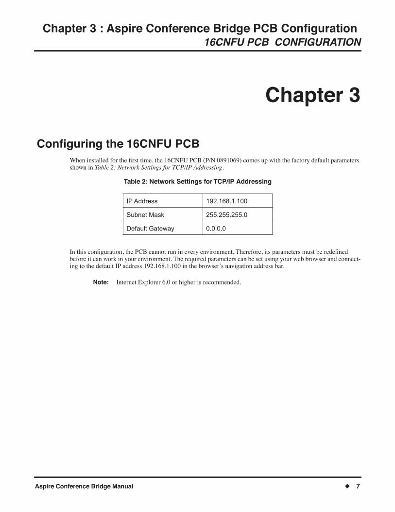
ConÞguring the 16CNFU PCBWhen installed for the Þrst time, the 16CNFU PCB (P/N 0891069) comes up with the factory default parameters shown in Table 2: Network Settings for TCP/IP Addressing.
Table 2: Network Settings for TCP/IP Addressing
In this conÞguration, the PCB cannot run in every environment. Therefore, its parameters must be redeÞned before it can work in your environment. The required parameters can be set using your web browser and connect-ing to the default IP address 192.168.1.100 in the browser�s navigation address bar.
Note: Internet Explorer 6.0 or higher is recommended.
IP Address 192.168.1.100
Subnet Mask 255.255.255.0
Default Gateway 0.0.0.0

Chapter 3 : Aspire Conference Bridge PCB ConÞguration 16CNFU PCB CONFIGURATION
8 ◆ Aspire Conference Bridge Manual
ConÞguring the PCAfter the Conference Bridge is installed in the Aspire M/L/XL cabinet, the PC that is communicating with the 16CNFU PCB must be conÞgured to recognize the PCB. The PC and 16CNFU PCB must be connected using a straight ethernet cable, crossover cable, and/or a small hub. To ensure proper communication between the PC and the 16CNFU PCB, they must be attached to the same network.
To conÞgure the PC:
1. Press Start and select Control Panel from the menu. Windows XP Professional operating system is used in this example. When using a differ-
ent Windows operating system, the screens may look slightly different.

Chapter 3 : Aspire Conference Bridge PCB ConÞguration 16CNFU PCB CONFIGURATION
Aspire Conference Bridge Manual ◆ 9
2. On the Control Panel menu, double-click on Network Connections.
3. From the Network Connections screen, double-click on Local Area Connection.

Chapter 3 : Aspire Conference Bridge PCB ConÞguration 16CNFU PCB CONFIGURATION
10 ◆ Aspire Conference Bridge Manual
4. When the Local Area Connection Status screen is displayed, click the Properties button.
5. From the Local Area Connection Properties screen, select Internet Protocol (TCP/IP) and then Properties.
Chapter 3 : Aspire Conference Bridge PCB ConÞguration 16CNFU PCB CONFIGURATION
Aspire Conference Bridge Manual ◆ 11
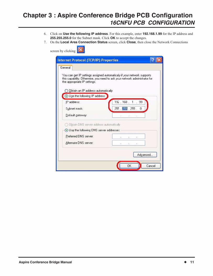
6. Click on Use the following IP address. For this example, enter 192.168.1.99 for the IP address and 255.255.255.0 for the Subnet mask. Click OK to accept the changes.
7. On the Local Area Connection Status screen, click Close, then close the Network Connections
screen by clicking .

Chapter 3 : Aspire Conference Bridge PCB ConÞguration 16CNFU PCB CONFIGURATION
12 ◆ Aspire Conference Bridge Manual
- For Your Notes -
Chapter 4 : Aspire Conference Bridge PCB Web ManagerUsing the Web Manager
Aspire Conference Bridge Manual ◆ 13
Chapter 4 : Aspire Conference Bridge PCB Web Manager
Using the Web Manager
Chapter 4
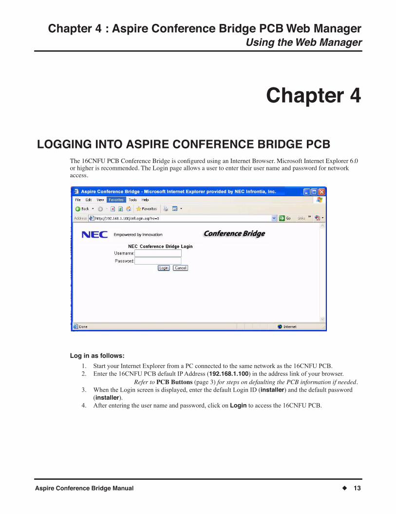
LOGGING INTO ASPIRE CONFERENCE BRIDGE PCBThe 16CNFU PCB Conference Bridge is conÞgured using an Internet Browser. Microsoft Internet Explorer 6.0 or higher is recommended. The Login page allows a user to enter their user name and password for network access.
Log in as follows:
1. Start your Internet Explorer from a PC connected to the same network as the 16CNFU PCB. 2. Enter the 16CNFU PCB default IP Address (192.168.1.100) in the address link of your browser.
Refer to PCB Buttons (page 3) for steps on defaulting the PCB information if needed.3. When the Login screen is displayed, enter the default Login ID (installer) and the default password
(installer). 4. After entering the user name and password, click on Login to access the 16CNFU PCB.

Chapter 4 : Aspire Conference Bridge PCB Web ManagerUsing the Web Manager
14 ◆ Aspire Conference Bridge Manual
Authentication Levels The 16CNFU PCB provides 3 different authentication levels: user, admin, and installer. When a new user is cre-ated, an authentication level for that user must be selected also. The user level determines the web pages that are available to the user and some of the conÞguration options that may be selected. The default user installer is a member of the installer group. Each user may also be identiÞed by different color codes. The groups are detailed below.
● User Group (Black color - user code)The user group is the most restricted group of the three levels. A member of the user group may create conferences only under their user name and view conferences that are created by them.
● Admin Group (Green color - user code) A member of the admin group may create, view, edit and delete conferences for any user. The member may also edit the conference application settings and create new admin and user members.
● Installer Group (Red color - user code) A member of the installer group has the same privileges as an admin user, plus the ability to view and modify the PCB conÞguration options. The installer may also upload new Þrmware to the PCB and reset the PCB from the web interface.

Chapter 4 : Aspire Conference Bridge PCB Web ManagerUsing the Web Manager
Aspire Conference Bridge Manual ◆ 15
MAIN PAGE After a technician logs into the 16CNFU PCB web interface, the main page is displayed. The main page is split into three regions: the navigation side bar, the status window near the bottom of the screen and the operations window in the center of the screen.

Chapter 4 : Aspire Conference Bridge PCB Web ManagerUsing the Web Manager
16 ◆ Aspire Conference Bridge Manual
Navigation Side Bar The side bar allows the user to navigate to the different areas of the web interface. When logged in as a member of the user group, only the Setup New Conference and Scheduled Conferences links are available. When logged in as a member of the admin group, the Administration and ConÞguration links are also available - though the information in the ConÞguration link is displayed, only the EMail ConÞguration can be edited. When logged in as a member of the installer group, the previously mentioned links plus all the ConÞguration options can be edited. The side bar is always visible from the main page.
Status Window The status window is always located at the bottom of the browser window. The status window displays the user name and administration level of the current user. A Logout button is provided that is clicked to log the user out of the web interface and return them to the login screen.
Operations Window The operations window provides access to the operation that is currently selected. When a user clicks on a side bar link, the target page is displayed in this window. When the user Þrst logs in, the Setup New Conference window is displayed by default.

Chapter 4 : Aspire Conference Bridge PCB Web ManagerUsing the Web Manager
Aspire Conference Bridge Manual ◆ 17
SETUP NEW CONFERENCE From the Setup New Conference window in the operations window, the user may make the initial selections for the conference.
● OrganizerThe user name of the organizer. When a user is logged in as a member of a group, the group name is supplied in this Þeld.
This Þeld is informational only and cannot be modiÞed.
● EmailThe Email address of the organizer.
● Subject LineThe subject line allows organizers to personalize the conference subject on a per conference basis.
● Start TimeThe start time of the conference call.
● DurationThe duration of the conference call.

Chapter 4 : Aspire Conference Bridge PCB Web ManagerUsing the Web Manager
18 ◆ Aspire Conference Bridge Manual
● No. of ParticipantsThe number of participants to invite to the conference besides the organizer. The maximum number of conÞgurable participants is Þfteen (15) plus the one (1) organizer for a total of sixteen (16) participants.
● Admission ControlAdministration Control, when checked, requires the organizer to allow (by pressing a key sequence) each new participant to enter the conference. When this function is enabled, the Host Required option must also be enabled. Clicking on Admission Control automatically enables Host Required.
The organizer enters the following codes at the organizer keyset to allow each new participant to enter the conference.
● Host RequiredHost Required, when checked, requires the organizer to be present for the conference to convene. No participants may enter the conference prior to the organizer entering the conference.
● Participant AnnounceAllows technicians to enable or disable the announcement prompt when conference participants enter scheduled conferences.
Scheduled conferences with nine (9) participants or more will automatically disable this function.
● Send NotiÞcationEnabling this object results in an Email notiÞcation being sent to all participants (for which Email addresses have been entered).
After the information is selected, the user may click Next>> to continue the conference setup. Clicking on Next>> loads the settings selected in another browser window and creates the forms for entering in the participant information.
● RecurrencesOrganizers may schedule a conference to recur in a cycle of 1-31. The number of recurrences is depen-dant on the number of days in the month. (Default: 0)
● Recurrence PeriodOrganizer may schedule conference to recur daily or weekly. (Default: Daily)
Admission Control: Access Codes
*5 Organizer Accept Participant
*6 Organizer Reject Participant

Chapter 4 : Aspire Conference Bridge PCB Web ManagerUsing the Web Manager
Aspire Conference Bridge Manual ◆ 19
From the new window, you can enter the Participant name information and Email information. The name and Email information is not required to create the conference. When complete, click Submit.

Chapter 4 : Aspire Conference Bridge PCB Web ManagerUsing the Web Manager
20 ◆ Aspire Conference Bridge Manual
When the conference creation is successful, a new conference report is generated with the conference informa-tion and passwords for the organizer and all the participants.
If the browser has pop-ups disabled, you may not see the New Conference Report page displayed. You can allow pop-ups for the TCP/IP address used for the Conference Bridge PCB under the TOOLS-POP-UP BLOCKER-POP-UP BLOCKER SETTINGS menu.
When Send NotiÞcation is enabled, an Email is sent to all participants with an Email address entered. The Email contains the conference start date, start time, duration, and their individual password. The reply address of the notiÞcation Emails is the organizer Email. An option to print the new conference report is provided at the bot-tom of the page. Clicking Close closes the report window.
Note that each password allows one person to enter the conference call. Once a password is used to sign into a conference, anyone else trying to use that same password to access the conference call will hear an �invalid pass-word� error message.

Chapter 4 : Aspire Conference Bridge PCB Web ManagerUsing the Web Manager
Aspire Conference Bridge Manual ◆ 21
When an error occurs during the conference creation process, the cause of the error is displayed and the user has the opportunity to modify the conference to resolve any scheduling conßicts.
When the Email ConÞguration options are not set properly, a message is displayed in the new conference report indicating that the notiÞcation Emails were not sent out. The user has the opportunity to resend the notiÞcations from the Conference Manager (page 22).
Chapter 4 : Aspire Conference Bridge PCB Web ManagerUsing the Web Manager
22 ◆ Aspire Conference Bridge Manual
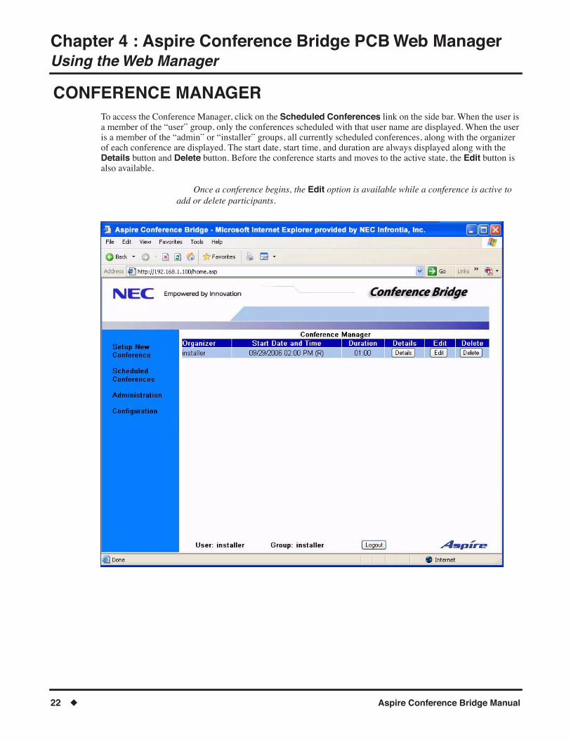
CONFERENCE MANAGER To access the Conference Manager, click on the Scheduled Conferences link on the side bar. When the user is a member of the �user� group, only the conferences scheduled with that user name are displayed. When the user is a member of the �admin� or �installer� groups, all currently scheduled conferences, along with the organizer of each conference are displayed. The start date, start time, and duration are always displayed along with the Details button and Delete button. Before the conference starts and moves to the active state, the Edit button is also available.
Once a conference begins, the Edit option is available while a conference is active to add or delete participants.
Chapter 4 : Aspire Conference Bridge PCB Web ManagerUsing the Web Manager
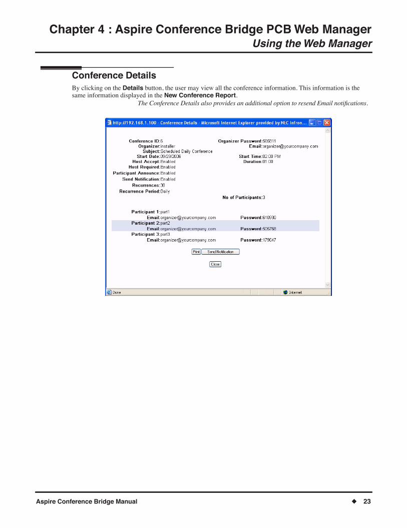
Aspire Conference Bridge Manual ◆ 23
Conference Details By clicking on the Details button, the user may view all the conference information. This information is the same information displayed in the New Conference Report.
The Conference Details also provides an additional option to resend Email notiÞcations.

Chapter 4 : Aspire Conference Bridge PCB Web ManagerUsing the Web Manager
24 ◆ Aspire Conference Bridge Manual
Edit Conference The Edit Conference window brings up a form with all the current conference information Þlled in. The user may modify any parameter of the conference, such as add or delete participants, etc.
Deleting a participant will only delete that participant�s information, and will not delete any other participant�s information.
When deleting a participant, if the Send NotiÞcation box is checked - an Email notiÞ-cation will be sent again to all participants. Uncheck this box if you do not wish to resend Email notiÞcation.

Chapter 4 : Aspire Conference Bridge PCB Web ManagerUsing the Web Manager
Aspire Conference Bridge Manual ◆ 25
Delete Conference When the Delete button is clicked from the Conference Manager, the user is prompted with a new browser window conÞrming that the delete operation should occur. When the user clicks No, the delete operation is can-celed. When the user clicks Yes, the conference is removed from the schedule.

Chapter 4 : Aspire Conference Bridge PCB Web ManagerUsing the Web Manager
26 ◆ Aspire Conference Bridge Manual
ADMINISTRATION To access the Conference Bridge status and conÞguration pages, click on the Administration link on the side bar. This link is available only to members of the admin and installer groups. The Þrst page displayed is the Con-ference Bridge Status information.
This option is displayed only for Admin and Installer password levels.

Chapter 4 : Aspire Conference Bridge PCB Web ManagerUsing the Web Manager
Aspire Conference Bridge Manual ◆ 27
● System TimeThe current date and time of the 16CNFU PCB.
● Bridge ModeThe mode of operation for the 16CNFU PCB (Simple and Advanced Mode).
Only the Advanced mode is available with the Aspire.
● No. of ChannelsThe number of channels available on the PCB.
● Max. Conf. DurationThe maximum conference duration.
● End Tone Alert TimeThe alert message is played to all participants at the speciÞed time before the end of the conference. A time of two minutes speciÞes that the end message be played two minutes before the conference ends.
● No. of Simple ConferencesThe number of conferences conÞgured in simple mode conÞguration.
Not available with the Aspire system.
● No. of Existing Conf.The number of currently scheduled conferences.
These Þelds are informational only and are derived from previously conÞgured Þelds.

Chapter 4 : Aspire Conference Bridge PCB Web ManagerUsing the Web Manager
28 ◆ Aspire Conference Bridge Manual
Edit Bridge ConÞguration Clicking on the Edit Bridge ConÞguration link takes the user to the Conference Bridge ConÞguration page.

Chapter 4 : Aspire Conference Bridge PCB Web Manager
Using the Web Manager
Aspire Conference Bridge Manual
◆
29
●
Max Participants Per Conf.
ConÞgures the maximum participants including the organizer in a conference. (Default = 16)
●
Max Conf. Duration
ConÞgures the maximum duration of a conference. (Default = 240 minutes)
●
End Tone Alert Time
ConÞgures the time that the end alert message is played. (Default = 6 minutes)
●
Use Custom Greeting
When enabled (by selecting the check box) the Conference Bridge will play the recorded personalized greeting. When disabled (unchecking the box), 16CNFU restores the factory default greeting.
●
Recording Personalized Greeting:
1. Dial into one of the 16CNFU extensions and enter the set code for recording a Personalized greeting.
PASSWORD: 243939#
Use Program 10-03-02 PCB Setup and enter the slot number of 16CNFU PCB to verify which ports are used (example: If the 16CNFU has been placed into slot 6, the phone displays:
10-03-02 = Slot No 6 ESI port 01 CH1 TEL 33
Port 33 [Extension 333] is the Þrst port assigned to the 16CNFU. Dial Extension 333 to dial into the 16CNFU PCB.
2. Listen to the series of prompts played to guide you through recording your personalized greeting.
The customized greeting is automatically enabled after you accept the newly recorded greeting.
Clicking on
Submit
sends the changes to the conference application. The conÞguration is saved to non-volatile memory so it is retained after a reset. Clicking on the
Cancel
button returns the user to the
Administration
page.

Chapter 4 : Aspire Conference Bridge PCB Web ManagerUsing the Web Manager
30 ◆ Aspire Conference Bridge Manual
User Accounts Clicking on the User Accounts link brings up the User Accounts Management page. Using this page, User Accounts may be added, edited, or deleted.
Chapter 4 : Aspire Conference Bridge PCB Web ManagerUsing the Web Manager
Aspire Conference Bridge Manual ◆ 31
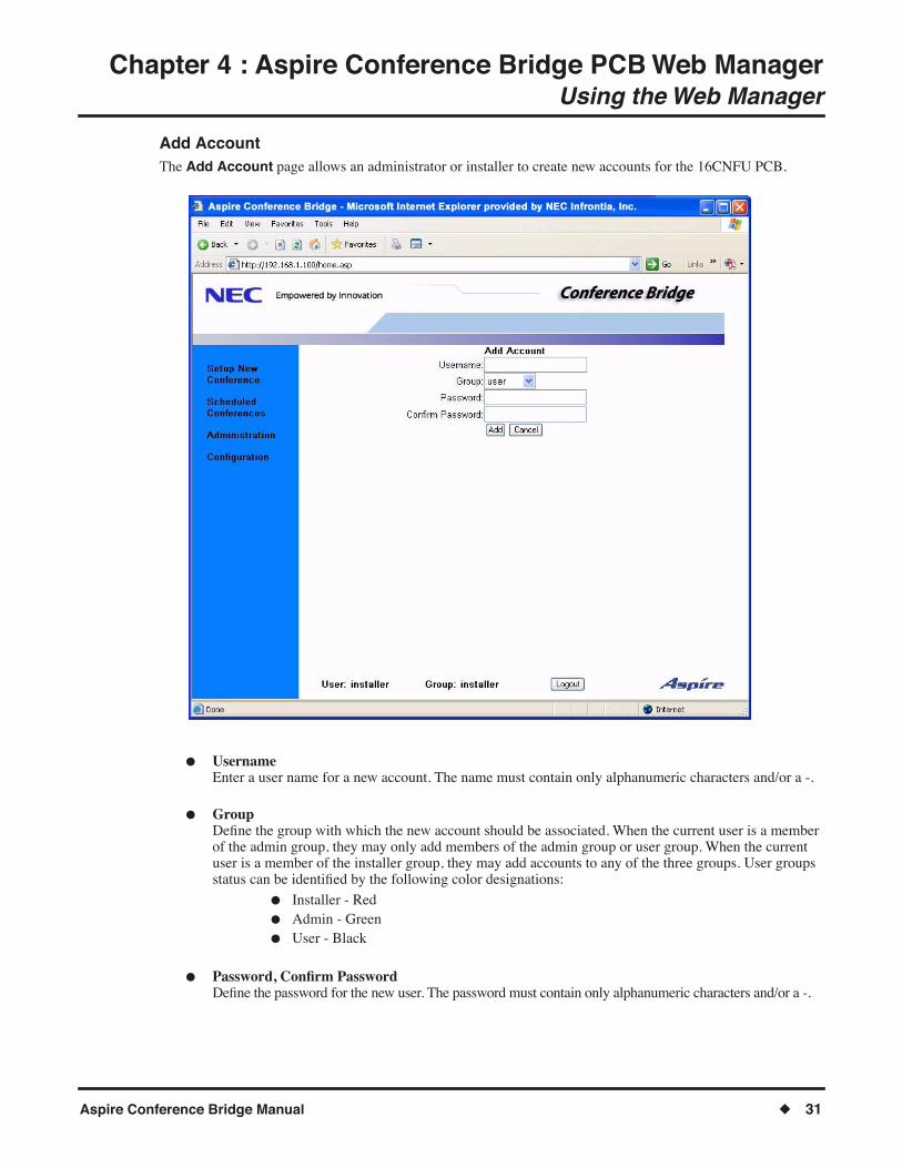
Add Account The Add Account page allows an administrator or installer to create new accounts for the 16CNFU PCB.
● UsernameEnter a user name for a new account. The name must contain only alphanumeric characters and/or a -.
● GroupDeÞne the group with which the new account should be associated. When the current user is a member of the admin group, they may only add members of the admin group or user group. When the current user is a member of the installer group, they may add accounts to any of the three groups. User groups status can be identiÞed by the following color designations:
● Installer - Red● Admin - Green● User - Black
● Password, ConÞrm PasswordDeÞne the password for the new user. The password must contain only alphanumeric characters and/or a -.
Chapter 4 : Aspire Conference Bridge PCB Web ManagerUsing the Web Manager
32 ◆ Aspire Conference Bridge Manual
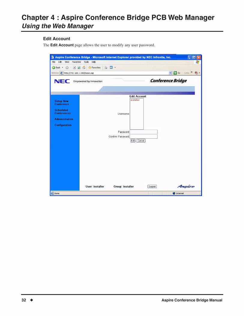
Edit AccountThe Edit Account page allows the user to modify any user password.

Chapter 4 : Aspire Conference Bridge PCB Web ManagerUsing the Web Manager
Aspire Conference Bridge Manual ◆ 33
Delete Account The Delete Account page allows the user to delete previously added user account(s).
The installer account cannot be deleted.

Chapter 4 : Aspire Conference Bridge PCB Web ManagerUsing the Web Manager
34 ◆ Aspire Conference Bridge Manual
Gain ConÞgurationThese Þelds are useful for attenuation applied to obtain adequate voice levels for the end users. It is recom-mended not to alter this value unless solving an issue related to voice levels. (Default = 0)
● Transmit/Receive GainBase gain value that is applied to all calls (Internal or External).
● Transmit/Receive Internal or External BiasTransmit/Receive levels for External and Internal calls.
More (+) positive setting increases the volume level. More (-) negative decreases the volume level. Example: When the following settings are applied: Transmit Gain = 2, Transmit Internal Bias = 2 Transmit Gain set for the channel of a call on an internal line would equal a total of 4.
● AGC ConÞgurationThese Þelds are useful when controlling the gain of the system in order to maintain consistent audio lev-els during a conference.
The default values are suggested baseline settings for the 16CNFU PCB. The values may need to be adjusted for optimal performance on your system.
Chapter 4 : Aspire Conference Bridge PCB Web ManagerUsing the Web Manager
Aspire Conference Bridge Manual ◆ 35
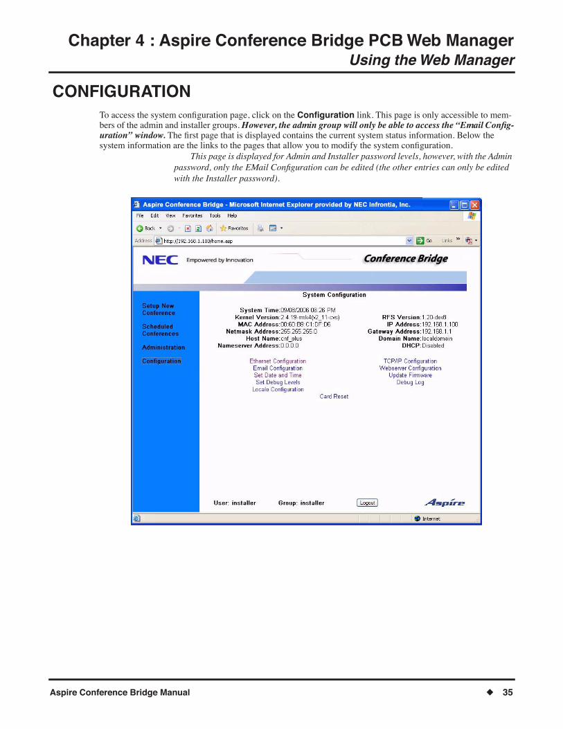
CONFIGURATIONTo access the system conÞguration page, click on the ConÞguration link. This page is only accessible to mem-bers of the admin and installer groups. However, the admin group will only be able to access the �Email ConÞg-uration� window. The Þrst page that is displayed contains the current system status information. Below the system information are the links to the pages that allow you to modify the system conÞguration.
This page is displayed for Admin and Installer password levels, however, with the Admin password, only the EMail ConÞguration can be edited (the other entries can only be edited with the Installer password).

Chapter 4 : Aspire Conference Bridge PCB Web ManagerUsing the Web Manager
36 ◆ Aspire Conference Bridge Manual
● System TimeThe current system time of the 16CNFU PCB.
● Kernel VersionThe version of the OS of the 16CNFU PCB.
● RFS VersionThe version of the Þrmware of the 16CNFU PCB.
● MAC AddressThe MAC address of the 16CNFU PCB.
● IP AddressThe IP address of the 16CNFU PCB.
● Netmask AddressThe subnet mask address of the 16CNFU PCB.
● Gateway AddressThe gateway address of the 16CNFU PCB.
● Host NameThe host name of the 16CNFU PCB.
● Domain NameThe domain name of the 16CNFU PCB.
● Nameserver AddressThe IP address of the nameserver to be used.
● DHCPIf enabled, DHCP is used to obtain the TCP/IP information.

Chapter 4 : Aspire Conference Bridge PCB Web ManagerUsing the Web Manager
Aspire Conference Bridge Manual ◆ 37
Ethernet ConÞgurationThe Ethernet Interface setting allows for manual conÞguration of the Ethernet port speed and mode. The ether-net interface can support 10MB or 100MB speed, and Full-Duplex or Half-Duplex mode setting (at default, this will be set to Auto Negotiate). When set to Auto Negotiate, the 16CNFU PCB will sense the peer connection (to wherever the cable is connected (e.g. Hub, Switch, or Router)) hardware capabilities and negotiate the best possi-ble speed and operation mode.
The new settings to the ethernet port are effective immediately after clicking Submit.Make sure that the peer (the other side of the Ethernet cable) is capable of Auto Negoti-
ate (some routers may not have this feature).

Chapter 4 : Aspire Conference Bridge PCB Web ManagerUsing the Web Manager
38 ◆ Aspire Conference Bridge Manual
TCP/IP ConÞgurationThe TCP/IP ConÞguration page allows the installer to modify the TCP/IP settings. When the Use DHCP for TCP/IP ConÞguration is set, the PCB uses DHCP to obtain the TCP/IP information. When the ConÞgure TCP/IP Manually button is checked, the PCB uses the information supplied by the users in the IP Settings text boxes. After clicking Submit, the user must reset the PCB for the new network settings to take affect.
When "Use DHCP" is checked, you will be required to consult with your Network Administrator to obtain the DHCP IP Address that has been assigned to the Conference Bridge 16CNFU PCB.
● Host NameDeÞne the host name of the 16CNFU PCB.
● IP AddressDeÞne the IP address of the 16CNFU PCB.
● Netmask AddressDeÞne the subnet mask address of the 16CNFU PCB.
● Gateway AddressDeÞne the gateway address of the 16CNFU PCB.
● Domain NameDeÞne the domain name of the 16CNFU PCB.
● Nameserver AddressDeÞne the IP address of the nameserver to be used for the DNS lookups.

Chapter 4 : Aspire Conference Bridge PCB Web ManagerUsing the Web Manager
Aspire Conference Bridge Manual ◆ 39
Email ConÞguration The Email ConÞguration page allows the installer to conÞgure the Email server settings that are used for Emailing conference notiÞcations.
The 16CNFU Email conÞguration supports SMTP mail server ONLY.Consult with your System Administrator for SMTP Server information. This option is displayed for Admin and Installer password levels, however, with the
Admin password, only the EMail ConÞguration can be edited (the other entries are dis-played but can only be edited with the Installer password).
Chapter 4 : Aspire Conference Bridge PCB Web ManagerUsing the Web Manager
40 ◆ Aspire Conference Bridge Manual
● Outgoing Mail Server (SMTP)DeÞne the network address of the SMTP server to be used.
● Outgoing Mail Server PortDeÞne the SMTP server port. This normally is set to 25.
● Server Requires AuthenticationWhen this is checked, the SMTP server requires messages sent to it to be authenticated to an account.
● Authentication User NameDeÞne the user name to use for the authentication.
● Authentication PasswordDeÞne the password to use for the authentication.
This must be entered every time the Email conÞguration is modiÞed when authentication is used.
● From Email AddressDeÞne the Email address displayed in the From Þeld on notiÞcations sent from the 16CNFU PCB.
● SubjectEnter the subject line of the notiÞcations sent from the 16CNFU PCB.
● Message IntroductionEnter the introduction that is printed before the conference details.
● Message ConclusionEnter the conclusion that is printed at the end of the Email address.
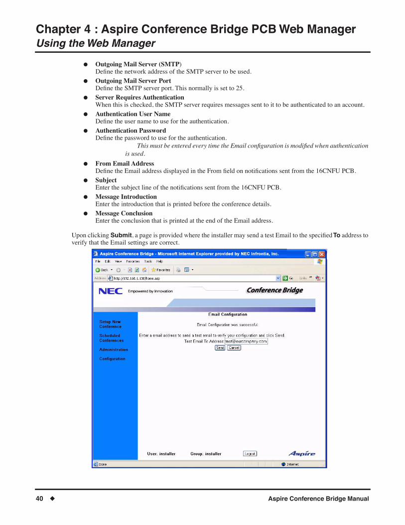
Upon clicking Submit, a page is provided where the installer may send a test Email to the speciÞed To address to verify that the Email settings are correct.
Chapter 4 : Aspire Conference Bridge PCB Web ManagerUsing the Web Manager
Aspire Conference Bridge Manual ◆ 41
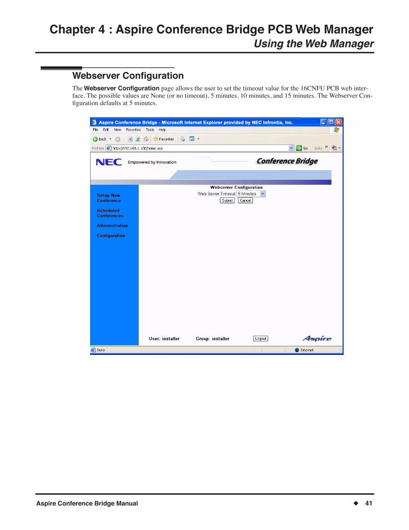
Webserver ConÞguration The Webserver ConÞguration page allows the user to set the timeout value for the 16CNFU PCB web inter-face. The possible values are None (or no timeout), 5 minutes, 10 minutes, and 15 minutes. The Webserver Con-Þguration defaults at 5 minutes.
Chapter 4 : Aspire Conference Bridge PCB Web ManagerUsing the Web Manager
42 ◆ Aspire Conference Bridge Manual
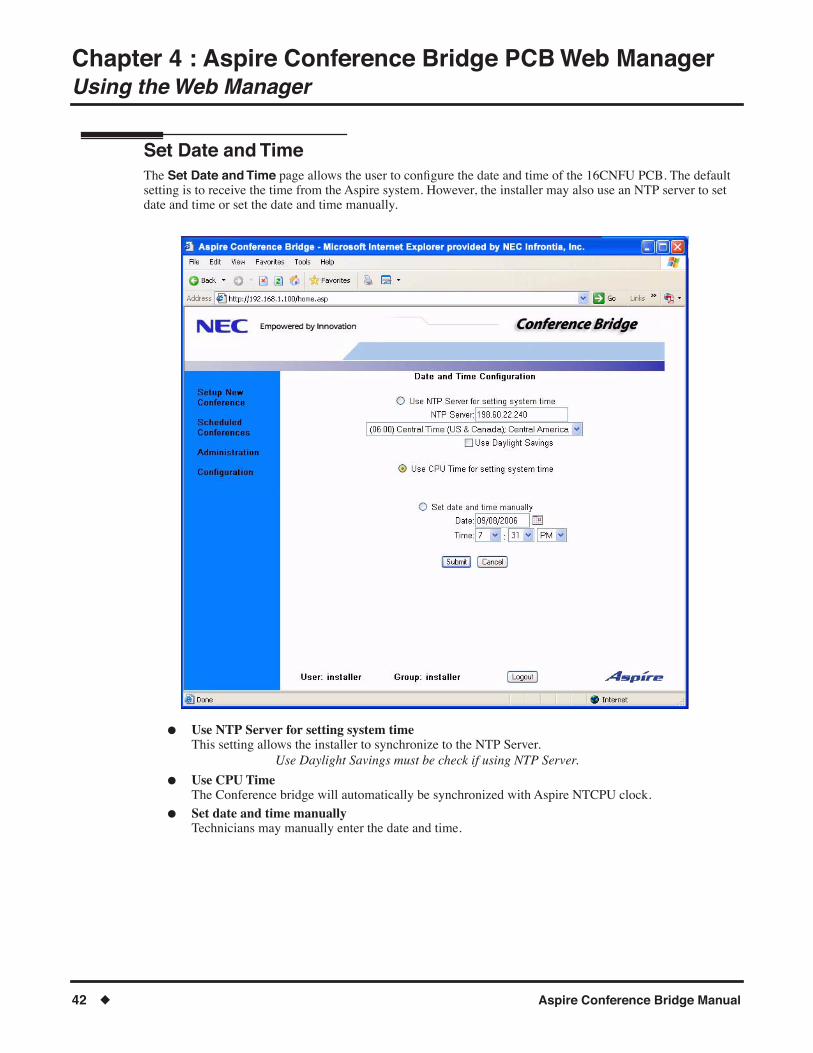
Set Date and Time The Set Date and Time page allows the user to conÞgure the date and time of the 16CNFU PCB. The default setting is to receive the time from the Aspire system. However, the installer may also use an NTP server to set date and time or set the date and time manually.
● Use NTP Server for setting system timeThis setting allows the installer to synchronize to the NTP Server.
Use Daylight Savings must be check if using NTP Server.
● Use CPU TimeThe Conference bridge will automatically be synchronized with Aspire NTCPU clock.
● Set date and time manuallyTechnicians may manually enter the date and time.
Chapter 4 : Aspire Conference Bridge PCB Web ManagerUsing the Web Manager
Aspire Conference Bridge Manual ◆ 43
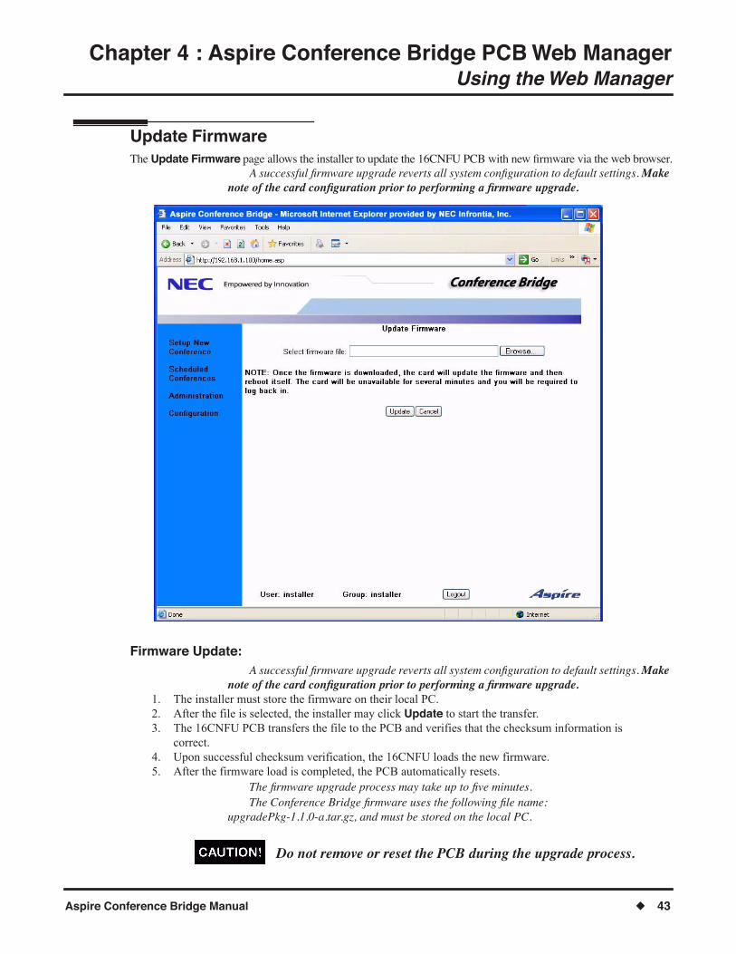
Update Firmware The Update Firmware page allows the installer to update the 16CNFU PCB with new Þrmware via the web browser.
A successful Þrmware upgrade reverts all system conÞguration to default settings. Make note of the card conÞguration prior to performing a Þrmware upgrade.
Firmware Update: A successful Þrmware upgrade reverts all system conÞguration to default settings. Make
note of the card conÞguration prior to performing a Þrmware upgrade.1. The installer must store the firmware on their local PC. 2. After the file is selected, the installer may click Update to start the transfer. 3. The 16CNFU PCB transfers the file to the PCB and verifies that the checksum information is
correct. 4. Upon successful checksum verification, the 16CNFU loads the new firmware. 5. After the firmware load is completed, the PCB automatically resets.
The Þrmware upgrade process may take up to Þve minutes. The Conference Bridge Þrmware uses the following Þle name:
upgradePkg-1.1.0-a.tar.gz, and must be stored on the local PC.
Do not remove or reset the PCB during the upgrade process.

Chapter 4 : Aspire Conference Bridge PCB Web ManagerUsing the Web Manager
44 ◆ Aspire Conference Bridge Manual
Set Debug LevelsThe Set Debug Levels page allows the installer to determine how much information should be sent to the debug log.
This page is used for analyzing communication errors and is intended for use by technical support personnel.
Chapter 4 : Aspire Conference Bridge PCB Web ManagerUsing the Web Manager
Aspire Conference Bridge Manual ◆ 45
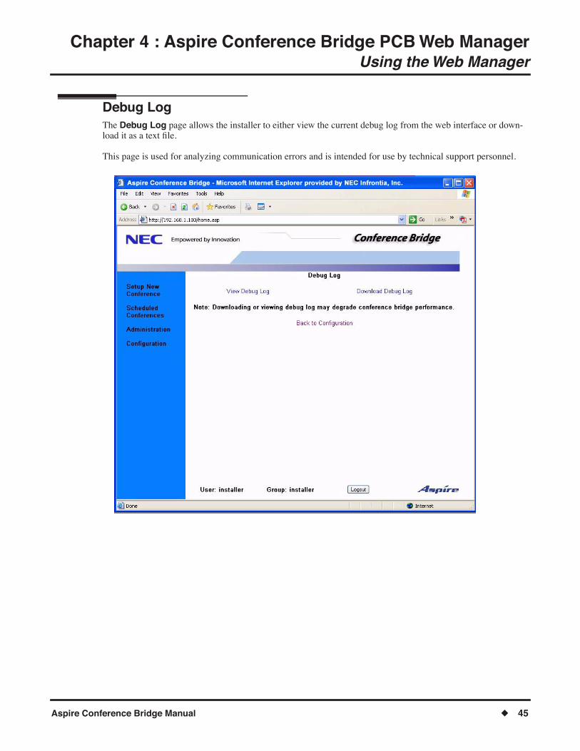
Debug LogThe Debug Log page allows the installer to either view the current debug log from the web interface or down-load it as a text Þle.
This page is used for analyzing communication errors and is intended for use by technical support personnel.

Chapter 4 : Aspire Conference Bridge PCB Web ManagerUsing the Web Manager
46 ◆ Aspire Conference Bridge Manual
LocaleThe Locale page allows the installer to select the location where the application is used - North America or Australia.
Chapter 4 : Aspire Conference Bridge PCB Web ManagerUsing the Web Manager
Aspire Conference Bridge Manual ◆ 47
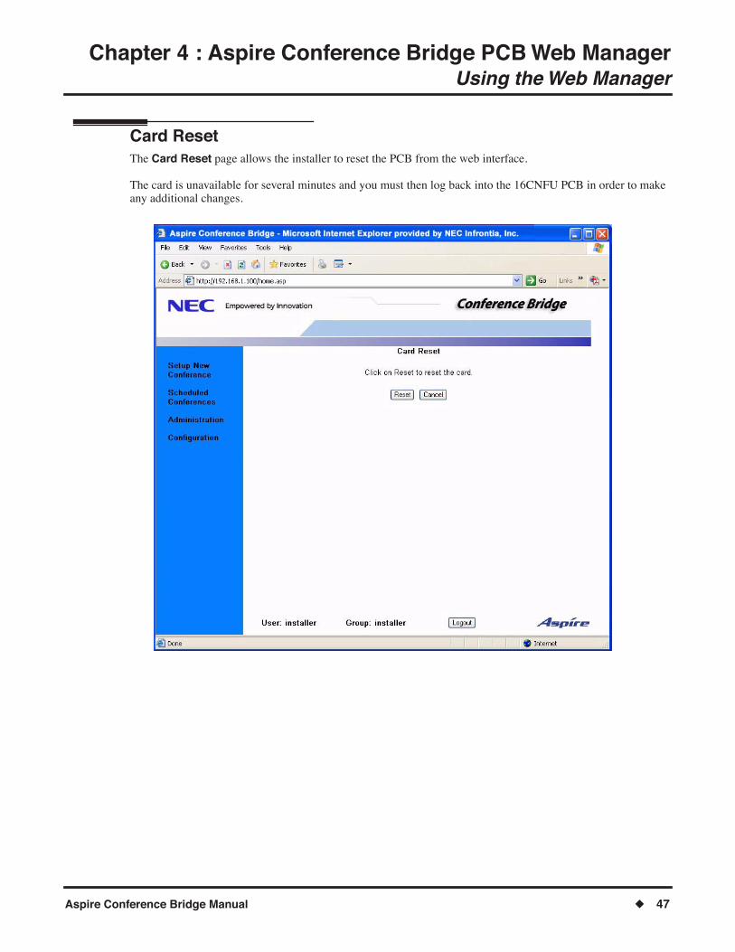
Card ResetThe Card Reset page allows the installer to reset the PCB from the web interface.
The card is unavailable for several minutes and you must then log back into the 16CNFU PCB in order to make any additional changes.

Chapter 4 : Aspire Conference Bridge PCB Web ManagerUsing the Web Manager
48 ◆ Aspire Conference Bridge Manual
- For Your Notes -

Appendix AGlossary
Aspire Conference Bridge Manual ◆ 49
Appendix A
Glossary
Glossary
The following terms are used within this document.
Term DeÞnition
Dynamic Host Control Protocol (DHCP)
A protocol for automatic TCP/IP configuration that provides static and dynamic address allocation and management.
Internet The global digital network.
Intranet A private digital network.
MAC Address A worldwide unique physical address required for all equipment on the internet.
MDIX Medium Dependent Interface Crossover
NTP Network Time Protocol
POP3 Short for Post Office Protocol, a protocol used to retrieve Email from a mail server.
Real-Time Transmission Real-Time Transmission is transmission in which there is no perceived delay in the transmission of a voice message or the response to it. This is a requirement for voice traffic.
Simple Mail Transfer Protocol (SMTP)
The TCP/IP protocol governing electronic mail transmissions and receptions. An application-level protocol which runs over TCP/IP, supporting text-oriented Email between devices supporting Message Handling Service (MHS).
Subnet Mask A number used to identify a sub-network so that an IP address can be shared on a LAN.
Transmission Control Protocol/Internet Protocol (TCP/IP)
Transmission Control Protocol/Internet Protocol (TCP/IP) is a networking protocol that provides communication across interconnected networks, between computers with diverse hardware architectures and various operating systems.

Appendix AGlossary
50 ◆ Aspire Conference Bridge Manual
- For Your Notes -
Appendix BConference Access Codes
Aspire Conference Bridge Manual ◆ 51
Appendix B
Conference Access Codes
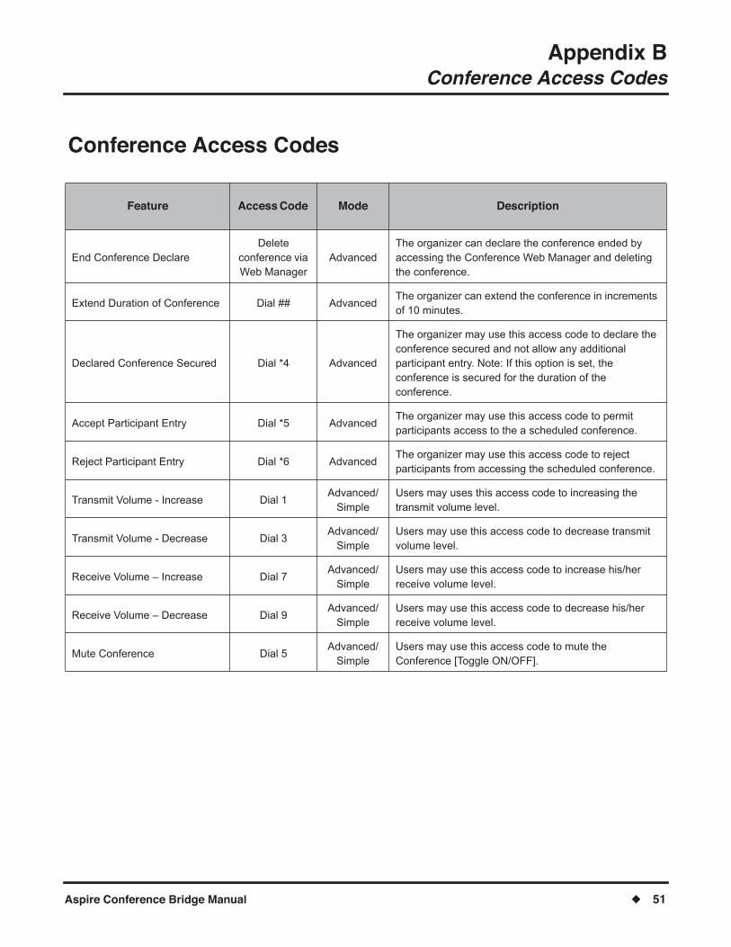
Conference Access Codes
Feature Access Code Mode Description
End Conference Declare Delete
conference via Web Manager
Advanced The organizer can declare the conference ended by accessing the Conference Web Manager and deleting the conference.
Extend Duration of Conference Dial ## Advanced The organizer can extend the conference in increments of 10 minutes.
Declared Conference Secured Dial *4 Advanced
The organizer may use this access code to declare the conference secured and not allow any additional participant entry. Note: If this option is set, the conference is secured for the duration of the conference.
Accept Participant Entry Dial *5 Advanced The organizer may use this access code to permit participants access to the a scheduled conference.
Reject Participant Entry Dial *6 Advanced The organizer may use this access code to reject participants from accessing the scheduled conference.
Transmit Volume - Increase Dial 1 Advanced/
Simple Users may uses this access code to increasing the transmit volume level.
Transmit Volume - Decrease Dial 3 Advanced/
Simple Users may use this access code to decrease transmit volume level.
Receive Volume � Increase Dial 7 Advanced/
Simple Users may use this access code to increase his/her receive volume level.
Receive Volume � Decrease Dial 9 Advanced/
Simple Users may use this access code to decrease his/her receive volume level.
Mute Conference Dial 5 Advanced/
Simple Users may use this access code to mute the Conference [Toggle ON/OFF].

Appendix BConference Access Codes
52 ◆ Aspire Conference Bridge Manual
- For Your Notes -

NEC Unified Solutions, Inc.4 Forest Parkway, Shelton, CT 06484
Tel: 800-365-1928 Fax: 203-926-5458www.necunifiedsolutions.com
Other Important Telephone Numbers
Sales: . . . . . . . . . . . . . . . . . . . . . . . . . . . . . . . . . . . .203-926-5450Customer Service: . . . . . . . . . . . . . . . . . . . . . . . . . . .203-926-5444Customer Service FAX: . . . . . . . . . . . . . . . . . . . . . . .203-926-5454Technical Service: . . . . . . . . . . . . . . . . . . . . . . . . . . .203-925-8801Discontinued Product Service: . . . . . . . . . . . . . . . . . .900-990-2541Technical Training: . . . . . . . . . . . . . . . . . . . . . . . . . . .203-926-5430Emergency Technical Service (After Hours) . . . . . . . .203-929-7920
(Excludes discontinued products)

(0893215)September 26, 2006, Rev 1 Printed in U.S.A.
NEC Unified Solutions, Inc.4 Forest Parkway, Shelton, CT 06484
TEL: 203-926-5400 FAX: 203-929-0535www.necunifiedsolutions.com


