198
Configuration — IP Routing and Multicast Avaya Ethernet Routing Switch 2500 Series 4.4 NN47215-503, 05.04 July 2012

Configuration — IP Routing and MulticastAvaya Ethernet Routing Switch 2500Series
4.4NN47215-503, 05.04
July 2012

© 2012 Avaya Inc.
All Rights Reserved.
Notice
While reasonable efforts have been made to ensure that theinformation in this document is complete and accurate at the time ofprinting, Avaya assumes no liability for any errors. Avaya reserves theright to make changes and corrections to the information in thisdocument without the obligation to notify any person or organization ofsuch changes.
Documentation disclaimer
“Documentation” means information published by Avaya in varyingmediums which may include product information, operating instructionsand performance specifications that Avaya generally makes availableto users of its products. Documentation does not include marketingmaterials. Avaya shall not be responsible for any modifications,additions, or deletions to the original published version ofdocumentation unless such modifications, additions, or deletions wereperformed by Avaya. End User agrees to indemnify and hold harmlessAvaya, Avaya's agents, servants and employees against all claims,lawsuits, demands and judgments arising out of, or in connection with,subsequent modifications, additions or deletions to this documentation,to the extent made by End User.
Link disclaimer
Avaya is not responsible for the contents or reliability of any linked Websites referenced within this site or documentation provided by Avaya.Avaya is not responsible for the accuracy of any information, statementor content provided on these sites and does not necessarily endorsethe products, services, or information described or offered within them.Avaya does not guarantee that these links will work all the time and hasno control over the availability of the linked pages.
Warranty
Avaya provides a limited warranty on its Hardware and Software(“Product(s)”). Refer to your sales agreement to establish the terms ofthe limited warranty. In addition, Avaya’s standard warranty language,as well as information regarding support for this Product while underwarranty is available to Avaya customers and other parties through theAvaya Support Web site: http://support.avaya.com. Please note that ifyou acquired the Product(s) from an authorized Avaya reseller outsideof the United States and Canada, the warranty is provided to you bysaid Avaya reseller and not by Avaya.
Licenses
THE SOFTWARE LICENSE TERMS AVAILABLE ON THE AVAYAWEBSITE, HTTP://SUPPORT.AVAYA.COM/LICENSEINFO/ AREAPPLICABLE TO ANYONE WHO DOWNLOADS, USES AND/ORINSTALLS AVAYA SOFTWARE, PURCHASED FROM AVAYA INC.,ANY AVAYA AFFILIATE, OR AN AUTHORIZED AVAYA RESELLER(AS APPLICABLE) UNDER A COMMERCIAL AGREEMENT WITHAVAYA OR AN AUTHORIZED AVAYA RESELLER. UNLESSOTHERWISE AGREED TO BY AVAYA IN WRITING, AVAYA DOESNOT EXTEND THIS LICENSE IF THE SOFTWARE WAS OBTAINEDFROM ANYONE OTHER THAN AVAYA, AN AVAYA AFFILIATE OR ANAVAYA AUTHORIZED RESELLER; AVAYA RESERVES THE RIGHTTO TAKE LEGAL ACTION AGAINST YOU AND ANYONE ELSEUSING OR SELLING THE SOFTWARE WITHOUT A LICENSE. BYINSTALLING, DOWNLOADING OR USING THE SOFTWARE, ORAUTHORIZING OTHERS TO DO SO, YOU, ON BEHALF OFYOURSELF AND THE ENTITY FOR WHOM YOU ARE INSTALLING,DOWNLOADING OR USING THE SOFTWARE (HEREINAFTERREFERRED TO INTERCHANGEABLY AS “YOU” AND “END USER”),AGREE TO THESE TERMS AND CONDITIONS AND CREATE ABINDING CONTRACT BETWEEN YOU AND AVAYA INC. OR THEAPPLICABLE AVAYA AFFILIATE ( “AVAYA”).
Copyright
Except where expressly stated otherwise, no use should be made ofmaterials on this site, the Documentation, Software, or Hardwareprovided by Avaya. All content on this site, the documentation and theProduct provided by Avaya including the selection, arrangement anddesign of the content is owned either by Avaya or its licensors and isprotected by copyright and other intellectual property laws including thesui generis rights relating to the protection of databases. You may notmodify, copy, reproduce, republish, upload, post, transmit or distributein any way any content, in whole or in part, including any code andsoftware unless expressly authorized by Avaya. Unauthorizedreproduction, transmission, dissemination, storage, and or use withoutthe express written consent of Avaya can be a criminal, as well as acivil offense under the applicable law.
Third-party components
Certain software programs or portions thereof included in the Productmay contain software distributed under third party agreements (“ThirdParty Components”), which may contain terms that expand or limitrights to use certain portions of the Product (“Third Party Terms”).Information regarding distributed Linux OS source code (for thoseProducts that have distributed the Linux OS source code), andidentifying the copyright holders of the Third Party Components and theThird Party Terms that apply to them is available on the Avaya SupportWeb site: http://support.avaya.com/Copyright.
Trademarks
The trademarks, logos and service marks (“Marks”) displayed in thissite, the Documentation and Product(s) provided by Avaya are theregistered or unregistered Marks of Avaya, its affiliates, or other thirdparties. Users are not permitted to use such Marks without prior writtenconsent from Avaya or such third party which may own the Mark.Nothing contained in this site, the Documentation and Product(s)should be construed as granting, by implication, estoppel, or otherwise,any license or right in and to the Marks without the express writtenpermission of Avaya or the applicable third party.
Avaya is a registered trademark of Avaya Inc.
All non-Avaya trademarks are the property of their respective owners,and “Linux” is a registered trademark of Linus Torvalds.
Downloading Documentation
For the most current versions of Documentation, see the AvayaSupport Web site: http://support.avaya.com.
Contact Avaya Support
See the Avaya Support Web site: http://support.avaya.com for productnotices and articles, or to report a problem with your Avaya product.For a list of support telephone numbers and contact addresses, go tothe Avaya Support Web site: http://support.avaya.com, scroll to thebottom of the page, and select Contact Avaya Support.
2 Configuration — IP Routing and Multicast July 2012Comments? [email protected]

Contents
Chapter 1: New in this release........................................................................................... 9Features.................................................................................................................................................... 9
Layer 3 Non-Local Static Routes (IP NLSR).................................................................................... 9IGMPv3 Snooping............................................................................................................................ 9IGMPv3 proxy................................................................................................................................... 9DHCP option 82 support.................................................................................................................. 10DHCP Server.................................................................................................................................... 10
Chapter 2: Introduction...................................................................................................... 11ACLI command modes.............................................................................................................................. 11
Chapter 3: IP routing fundamentals.................................................................................. 13IP addressing overview............................................................................................................................. 13
Subnet addressing........................................................................................................................... 14IP routing................................................................................................................................................... 15
IP routing using VLANs.................................................................................................................... 16Local routes...................................................................................................................................... 16Static routes..................................................................................................................................... 18Layer 3 Non-Local Static Routes (IP NLSR).................................................................................... 19Default routes................................................................................................................................... 20Route scaling.................................................................................................................................... 20Management VLAN.......................................................................................................................... 20
DHCP Server............................................................................................................................................ 23DHCP Server usage examples........................................................................................................ 25
Related routing features............................................................................................................................ 37BootP/DHCP relay............................................................................................................................ 37DHCP option 82 support.................................................................................................................. 40UDP broadcast forwarding............................................................................................................... 41
Routing feature capabilities and limitations............................................................................................... 46Chapter 4: IGMP fundamentals.......................................................................................... 47
Overview of IP multicast............................................................................................................................ 47Multicast groups............................................................................................................................... 48Multicast addresses.......................................................................................................................... 49
IGMP overview.......................................................................................................................................... 49IGMPv1 operation............................................................................................................................ 49IGMPv2 operation............................................................................................................................ 50IGMPv3 operation............................................................................................................................ 52IGMP requests for comment............................................................................................................ 53
IGMP snooping......................................................................................................................................... 53IGMPv3 snooping............................................................................................................................. 55IGMP proxy...................................................................................................................................... 56IGMPv3 proxy................................................................................................................................... 58Forwarding of reports....................................................................................................................... 58Static mrouter port and nonquerier................................................................................................... 58Unknown multicast packet filtering................................................................................................... 59Robustness value............................................................................................................................. 60
Configuration — IP Routing and Multicast July 2012 3

IGMP snooping configuration rules.................................................................................................. 60Default IGMP values........................................................................................................................ 61IGMP snooping interworking with Windows clients.......................................................................... 61
Chapter 5: IP routing configuration using ACLI............................................................... 63IP routing configuration procedures.......................................................................................................... 63Configuring global IP routing status.......................................................................................................... 63Displaying global IP routing status............................................................................................................ 64Configuring an IP address for a VLAN...................................................................................................... 64Configuring IP routing status on a VLAN.................................................................................................. 65Displaying the IP address configuration and routing status for a VLAN................................................... 65Displaying IP routes.................................................................................................................................. 66
Chapter 6: Static route configuration using ACLI............................................................ 69Configuring a static route.......................................................................................................................... 69Displaying static routes............................................................................................................................. 70Configuring a management route............................................................................................................. 71Displaying the management routes.......................................................................................................... 72
Chapter 7: DHCP relay configuration using ACLI............................................................ 73DHCP relay configuration procedures...................................................................................................... 73Enabling global DHCP relay...................................................................................................................... 74Disabling global DHCP relay..................................................................................................................... 74Setting global DHCP relay to default........................................................................................................ 75Displaying the global DHCP relay status.................................................................................................. 75Displaying IP DHCP client parameters..................................................................................................... 76Specifying a local DHCP relay agent and remote DHCP server............................................................... 76Displaying the DHCP relay configuration.................................................................................................. 77Configuring DHCP relay on a VLAN......................................................................................................... 78Displaying the DHCP relay configuration for a VLAN............................................................................... 79Displaying DHCP relay counters............................................................................................................... 80Clearing DHCP relay counters for a VLAN............................................................................................... 81Configuring DHCP Relay Option 82 globally using ACLI.......................................................................... 81Configuring DHCP Relay with Option 82 for a VLAN using ACLI............................................................. 82Configuring DHCP Forwarding Maximum Frame size using ACLI............................................................ 82Assigning a DHCP Relay Option 82 subscriber ID to a port using ACLI.................................................. 82Viewing DHCP Relay using ACLI.............................................................................................................. 83
Chapter 8: DHCP Server Configuration using ACLI........................................................ 85Displaying the DHCP Server status using ACLI....................................................................................... 85Displaying DHCP Server IP address pools using ACLI............................................................................ 85Displaying DHCP Server IP address leases using ACLI.......................................................................... 86Enabling DHCP Server using ACLI........................................................................................................... 86Disabling the DHCP Server using ACLI.................................................................................................... 87Configuring DHCP Server IP address lease duration using ACLI............................................................ 87Resetting DHCP Server lease duration to default using ACLI.................................................................. 88Configuring DHCP Server routers using ACLI.......................................................................................... 88Clearing DHCP Server router list using ACLI............................................................................................ 89Deleting DHCP Server routers using ACLI............................................................................................... 89Configuring the Domain Name System server using ACLI....................................................................... 90Clearing the Domain Name System server list using ACLI....................................................................... 91
4 Configuration — IP Routing and Multicast July 2012

Deleting Domain Name System servers using ACLI................................................................................. 91Creating a DHCP Server IP address pool using ACLI.............................................................................. 92Configuring DHCP Server IP address pool options using ACLI................................................................ 92DHCP Server Option 43 vendor specific information................................................................................ 95DHCP Server Option 241 parameters....................................................................................................... 98Deleting Option 241 parameters for DHCP server pool............................................................................ 105Deleting Option 242 parameters for DHCP server pool............................................................................ 106Disabling DHCP Server IP address pools using ACLI.............................................................................. 106Configuring static IP addresses using ACLI.............................................................................................. 107Creating the IP DHCP Server Pool for a Vendor Class Identifier.............................................................. 108
Chapter 9: UDP broadcast forwarding configuration using ACLI.................................. 109UDP broadcast forwarding configuration procedures............................................................................... 109Configuring UDP protocol table entries..................................................................................................... 110Displaying the UDP protocol table............................................................................................................ 110Configuring a UDP forwarding list............................................................................................................. 111Applying a UDP forwarding list to a VLAN................................................................................................ 112Displaying the UDP broadcast forwarding configuration........................................................................... 113Clearing UDP broadcast counters on an interface.................................................................................... 114
Chapter 10: Directed broadcasts configuration using ACLI........................................... 117Configuring directed broadcasts............................................................................................................... 117Displaying the directed broadcast configuration....................................................................................... 117
Chapter 11: Static ARP and Proxy ARP configuration using ACLI ................................ 119Static ARP configuration........................................................................................................................... 119Configuring a static ARP entry.................................................................................................................. 119Displaying the ARP table.......................................................................................................................... 120Displaying ARP entries............................................................................................................................. 120Configuring a global timeout for ARP entries............................................................................................ 122Clearing the ARP cache............................................................................................................................ 122Proxy ARP configuration........................................................................................................................... 122Navigation................................................................................................................................................. 123Configuring proxy ARP status................................................................................................................... 123Displaying proxy ARP status on a VLAN.................................................................................................. 124
Chapter 12: IP blocking configuration using ACLI.......................................................... 125Configuring IP blocking for a stack........................................................................................................... 125Displaying IP blocking status.................................................................................................................... 125
Chapter 13: IGMP snooping configuration using ACLI................................................... 127Configuring IGMP snooping on a VLAN................................................................................................... 127Configuring IGMP Multicast no flood......................................................................................................... 128Enabling IGMP Multicast no flood............................................................................................................. 128Disabling IGMP Multicast no flood............................................................................................................ 128Displaying IGMP Multicast no flood status................................................................................................ 129Configuring IGMP proxy on a VLAN......................................................................................................... 130Configuring static mrouter ports on a VLAN............................................................................................. 131Configuring IGMP parameters on a VLAN................................................................................................ 132Displaying IGMP interface information...................................................................................................... 133Displaying IGMP group membership information..................................................................................... 135Displaying IGMP cache Information using ACLI....................................................................................... 137
Configuration — IP Routing and Multicast July 2012 5
Flushing the IGMP router table using ACLI.............................................................................................. 138Configuring IGMP router alert on a VLAN using ACLI.............................................................................. 138
Chapter 14: IP routing configuration using Enterprise Device Manager....................... 141IP routing configuration procedures.......................................................................................................... 141Configuring global IP routing status and ARP lifetime.............................................................................. 142Configuring an IP address and enabling routing for a VLAN.................................................................... 143Displaying configured IP Addresses......................................................................................................... 144
Chapter 15: Static route configuration using Enterprise Device Manager.................... 147Configuring static routes........................................................................................................................... 147Displaying IP routes.................................................................................................................................. 149Filtering route information......................................................................................................................... 150Displaying TCP information for the switch................................................................................................ 151Displaying TCP Connections.................................................................................................................... 152Displaying TCP Listeners.......................................................................................................................... 152Displaying UDP endpoints........................................................................................................................ 153
Chapter 16: DHCP relay configuration using Enterprise Device Manager.................... 157DHCP relay configuration procedures...................................................................................................... 157Enabling DHCP Forwarding...................................................................................................................... 158
Configuring DHCP Forwarding maximum frame size globally using EDM....................................... 158Disabling DHCP Forwarding..................................................................................................................... 159Configuring DHCP Relay.......................................................................................................................... 159Configuring DHCP Relay with Option 82 globally using EDM.................................................................. 160Configuring DHCP parameters on a VLAN............................................................................................... 161Configuring DHCP Relay with Option 82 for a VLAN using EDM............................................................. 162Displaying and graphing DHCP counters on a VLAN............................................................................... 162Assigning a DHCP Relay Option 82 subscriber ID to a port using EDM.................................................. 163
Chapter 17: DHCP Server configuration using Enterprise Device Manager................. 165Enabling DHCP Server using EDM........................................................................................................... 165Displaying DHCP Server Pool using EDM................................................................................................ 166Configuring a DHCP Server Pool using EDM........................................................................................... 168DHCP Server Option 43 vendor specific information................................................................................ 170Deleting a DHCP Server Pool using EDM................................................................................................ 173Configuring DHCP Server Pool Options using EDM................................................................................. 174Deleting DHCP Server Pool Options using EDM...................................................................................... 175
Chapter 18: UDP broadcast forwarding configuration using Enterprise DeviceManager............................................................................................................................... 177
UDP broadcast forwarding configuration procedures............................................................................... 177Configuring UDP protocol table entries..................................................................................................... 178Configuring UDP forwarding entries.......................................................................................................... 179Configuring a UDP forwarding list............................................................................................................. 179Applying a UDP forwarding list to a VLAN................................................................................................ 180
Chapter 19: Static ARP and Proxy ARP configuration using Enterprise DeviceManager............................................................................................................................... 183
Configuring static ARP entries.................................................................................................................. 183Configuring Proxy ARP............................................................................................................................. 184
Chapter 20: IGMP snooping configuration using Enterprise Device Manager............. 187Configuring IGMP snooping...................................................................................................................... 187
6 Configuration — IP Routing and Multicast July 2012

Viewing IGMP groups............................................................................................................................... 188Displaying IGMP group information using EDM........................................................................................ 189Displaying IGMP cache information using EDM....................................................................................... 190Specifying an IP address to be allowed to flood a VLAN using EDM....................................................... 191Configuring IGMP interface parameters and flushing IGMP tables using EDM........................................ 192Configuring IGMP snoop, proxy and static mrouter ports on a VLAN using EDM.................................... 194IGMP Multicast no flood............................................................................................................................ 195
Enabling IGMP Multicast no flood.................................................................................................... 195Disabling IGMP Multicast no flood................................................................................................... 196
Viewing the MAC Multicast Filter Table..................................................................................................... 196Viewing the IP Address Multicast Filter Table........................................................................................... 197
Configuration — IP Routing and Multicast July 2012 7

8 Configuration — IP Routing and Multicast July 2012

Chapter 1: New in this release
The following section details the new features in Avaya Ethernet Routing Switch 2500 Series Configuration—IP Routing and Multicast for Release 4.4.
FeaturesSee the following sections for information about feature changes.
Layer 3 Non-Local Static Routes (IP NLSR)You can use IP NLSR when the next-hop IP address is not directly reachable from the switchor when there are multiple paths to a network but the number of static routes can be reducedby using only one route with a remote gateway.
IGMPv3 SnoopingIn IGMPv3 snooping mode, the switch recognizes IGMPv3 reports and queries and can:
• recognize whether a source list is populated or blank
• identify the specific sources to filter for every multicast group a client joins to
• understand and process all IGMPv3 query types, INCLUDE and EXCLUDE IGMPv3report types
The following are supported:
• source filtering based on ALLOW and BLOCK, IGMPv3 report types
IGMPv3 proxyWith IGMPv3 proxy enabled, if the switch receives multiple reports for the same multicastgroup, it does not transmit each report to the upstream multicast router. Instead, the switchforwards the first report to the querier and suppresses the rest.
Configuration — IP Routing and Multicast July 2012 9

If new information emerges, for example if the switch adds another multicast group or receivesa query since the last report was transmitted upstream, then the switch forwards a new reportto the multicast router ports.
DHCP option 82 supportDHCP option 82 is an extension of Dynamic Host Configuration Protocol (RFC3046 andRFC3993) that enables the switch to send information about DHCP clients to the authenticatingDHCP server to assist in tracking end device locations.
DHCP ServerIf you require local provision of TCP/IP addresses and have no separate DHCP Server or otherdevice available to provide the service to local hosts, DHCP Server is included on the switch.You can use the DHCP Server feature to provide and manage client IPv4 addresses in yournetwork and eliminate manual TCP/IP configuration. DHCP Server is disabled by default.
New in this release
10 Configuration — IP Routing and Multicast July 2012Comments? [email protected]

Chapter 2: Introduction
This document provides procedures and conceptual information to configure IP routing features on theAvaya Ethernet Routing Switch 2500 Series, including static routes, Proxy ARP, DHCP Relay, and UDPforwarding. It also provides procedures and conceptual information to manage multicast traffic using IGMPsnooping.
ACLI command modesACLI provides the following command modes:
• User EXEC
• Privileged EXEC
• Global Configuration
• Interface Configuration
Mode access is determined by access permission levels and password protection.
If no password is set, you can enter ACLI in User EXEC mode and use the enable commandto move to the next level (Privileged EXEC mode). However, if you have read-only access, youcannot progress beyond User EXEC mode, the default mode. If you have read-write accessyou can progress from the default mode through all of the available modes.
With sufficient permission, you can use the rules in the following table to move between thecommand modes.
Command mode andsample prompt
Entrance commands Exit commands
User EXEC2526T>
No entrance command,default mode
exitorlogout
Privileged EXEC2526T#
enable exitorlogout
Global Configuration2526T(config)#
From Privileged EXECmode, enter:configure
To return to Privileged EXECmode, enter:endorexit
Configuration — IP Routing and Multicast July 2012 11

Command mode andsample prompt
Entrance commands Exit commands
To exit ACLI completely,enter:logout
Interface Configuration2526T(config-if)#
From Global Configurationmode, to configure a port,enter:interfacefastethernet <portnumber>To configure a VLAN, enter:interface vlan<vlan number>
To return to GlobalConfiguration mode, enter:exitTo return to Privileged EXECmode, enter:endTo exit ACLI completely,enter:logout
For more information, see Avaya Ethernet Routing Switch 2500 Series Fundamentals(NN47215-102).
Introduction
12 Configuration — IP Routing and Multicast July 2012Comments? [email protected]

Chapter 3: IP routing fundamentals
This chapter provides an introduction to IP routing and related features used in the Avaya Ethernet RoutingSwitch 2500 Series.
IP addressing overviewAn IP version 4 (IPv4) address consists of 32 bits expressed in a dotted-decimal format(XXX.XXX.XXX.XXX). The IPv4 address space is divided into classes, with classes A, B, andC reserved for unicast addresses, and accounting for 87.5 percent of the 32-bit IP addressspace. Class D is reserved for multicast addressing. The following table lists the breakdownof the IP address space by address range and mask.
Table 1: IP address classifications
Class Address Range Mask Number ofNetworks
Nodes perNetwork
A 1.0.0.0 - 127.0.0.0 255.0.0.0 127 16 777 214
B 128.0.0.0 - 191.255.0.0 255.255.0.0 16 384 65 534
C 192.0.0.0 - 223.255.255.0 255.255.255.0 2 097 152 255
D 224.0.0.0 -239.255.255.254
E 240.0.0.0 -240.255.255.255
Note:Class D addresses are primarily reserved for multicast operations, although theaddresses 224.0.0.5 and 224.0.0.6 are used by OSPF and 224.0.0.9 is used by RIP
Note:Although technically part of Class A addressing, network 127 is reserved for loopback.
Note:Class E addresses are reserved for research purposes.
To express an IP address in dotted-decimal notation, each octet of the IP address is convertedto a decimal number and separated by decimal points. For example, the 32-bit IP address
Configuration — IP Routing and Multicast July 2012 13

10000000 00100000 00001010 10100111 is expressed in dotted-decimal notation as128.32.10.167.
Each IP address class, when expressed in binary notation, has a different boundary pointbetween the network and host portions of the address, as shown in the following figure. Thenetwork portion is a network number field from 8 through 24 bits. The remaining 8 through 24bits identify a specific host on the network.
Figure 1: Network and host boundaries in IP address classes
Subnet addressingSubnetworks (or subnets) are an extension of the IP addressing scheme. With subnets,organizations can use one IP address range for multiple networks. Subnets are two or morephysical networks that share a common network-identification field (the network portion of the32-bit IP address).
A subnet address is created by increasing the network portion to include a subnet address,thus decreasing the host portion of the IP address. For example, in the address 128.32.10.0,the network portion is 128.32, while the subnet is found in the first octet of the host portion(10). A subnet mask is applied to the IP address and identifies the network and host portionsof the address.
The following table illustrates how subnet masks used with Class B and Class C addressescan create differing numbers of subnets and hosts. This example shows the use of the zerosubnet, which is permitted on a Avaya Ethernet Routing Switch 2500 Series.
IP routing fundamentals
14 Configuration — IP Routing and Multicast July 2012Comments? [email protected]
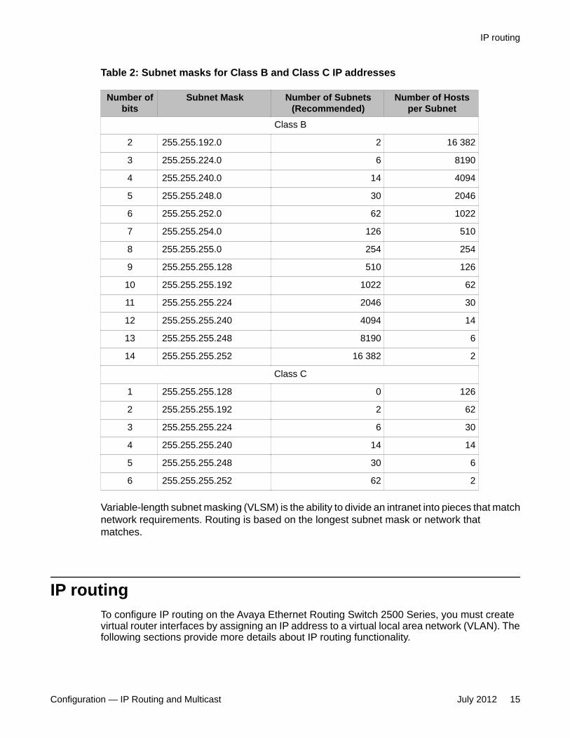
Table 2: Subnet masks for Class B and Class C IP addresses
Number ofbits
Subnet Mask Number of Subnets(Recommended)
Number of Hostsper Subnet
Class B
2 255.255.192.0 2 16 382
3 255.255.224.0 6 8190
4 255.255.240.0 14 4094
5 255.255.248.0 30 2046
6 255.255.252.0 62 1022
7 255.255.254.0 126 510
8 255.255.255.0 254 254
9 255.255.255.128 510 126
10 255.255.255.192 1022 62
11 255.255.255.224 2046 30
12 255.255.255.240 4094 14
13 255.255.255.248 8190 6
14 255.255.255.252 16 382 2
Class C
1 255.255.255.128 0 126
2 255.255.255.192 2 62
3 255.255.255.224 6 30
4 255.255.255.240 14 14
5 255.255.255.248 30 6
6 255.255.255.252 62 2
Variable-length subnet masking (VLSM) is the ability to divide an intranet into pieces that matchnetwork requirements. Routing is based on the longest subnet mask or network thatmatches.
IP routingTo configure IP routing on the Avaya Ethernet Routing Switch 2500 Series, you must createvirtual router interfaces by assigning an IP address to a virtual local area network (VLAN). Thefollowing sections provide more details about IP routing functionality.
IP routing
Configuration — IP Routing and Multicast July 2012 15
For a more detailed description about VLANs and their use, see Avaya Ethernet Routing Switch2500 Series, Configuration - VLANs, Spanning Tree, and Link Aggregation(NN47215–501).
IP routing using VLANsThe Avaya Ethernet Routing Switch 2500 Series, supports wire-speed IP routing betweenVLANs. To create a virtual router interface for a specified VLAN, you must associate an IPaddress with the VLAN.
The virtual router interface is not associated with any specific port. The VLAN IP address canbe reached through any of the ports in the VLAN. The assigned IP address also serves as thegateway through which packets are routed out of that VLAN. Routed traffic can be forwardedto another VLAN within the switch or stack.
When the Avaya Ethernet Routing Switch 2500 Series, is routing IP traffic between differentVLANs, the switch is considered to be running in Layer 3 mode; otherwise, the switch runs inLayer 2 mode. When you assign an IP address to a Layer 2 VLAN, the VLAN becomes aroutable Layer 3 VLAN. You can assign a single and unique IP address to each VLAN.
You can configure the global status of IP routing to be enabled or disabled on the AvayaEthernet Routing Switch 2500 Series,. By default, IP routing is disabled.
In this release, the Avaya Ethernet Routing Switch 2500 Series, supports local routes and staticroutes. With local routing, the switch automatically creates routes to each of the local Layer 3VLAN interfaces. With static routing, you must manually enter the routes to the destination IPaddresses.
Local routesWith routing globally enabled, if you assign an IP address to a VLAN, IP routing is enabled forthat VLAN. In addition, for each IP address assigned to a VLAN interface, the Ethernet RoutingSwitch adds a directly connected or local route to its routing table based on the IP address/mask assigned.
Local routing example
The following figure shows how the Ethernet Routing Switch can route between Layer 3VLANs. In this example, the Ethernet Routing Switch has two VLANs configured. IP Routingis enabled globally on the switch and on the VLANs, each of which has an assigned IPaddress.
IP routing fundamentals
16 Configuration — IP Routing and Multicast July 2012Comments? [email protected]

Figure 2: Local routes example
IP address 10.100.1.1/24 is assigned to VLAN 100, and IP address 10.200.1.1/24 is assignedto VLAN 200. As IP Routing is enabled, two local routes become active on the Avaya EthernetRouting Switch as described in the following table.
Network Net-mask Next-hop Type1 10.100.1.0 255.255.255.0 10.100.1.1 LOCAL
2 10.200.1.0 255.255.255.0 10.200.1.1 LOCAL
At this stage, both hosts A (10.200.1.10) and B (10.100.1.10) are reachable from the EthernetRouting Switch. However, to achieve Layer 3 connectivity between A and B, additionalconfiguration is required. Host A must know how to reach network 10.100.1.0/24, and host Bmust know how to reach network 10.200.1.0/24.
On host A, you must configure a route to network 10.100.1.0/24 through 10.200.1.1, orconfigure 10.200.1.1 as the default gateway for the host.
On host B, you must configure a route to network 10.200.1.0/24 through 10.100.1.1, orconfigure 10.100.1.1 as the default gateway for the host.
With these routes configured, the Ethernet Routing Switch can perform inter-VLAN routing,and packets can flow between hosts A and B.
IP routing
Configuration — IP Routing and Multicast July 2012 17

Static routesAfter you create routable VLANs though IP address assignment, you can create static routes.With static routes, you can manually create specific routes to a destination IP address. In thisrelease, the Ethernet Routing Switch supports local static routes only. For a route to becomeactive on the switch, the next-hop IP address for the route must be on a directly connectednetwork. Nonlocal static routes are not supported.
Static routes are not easily scalable. Thus, in a large or growing network, this type of routemanagement may not be optimal.
Static routing example
The following figure shows an example of static routing on the Ethernet Routing Switch.
Figure 3: Static routesIn this example, two Layer 3 devices are used to create a physical link between hosts A andB. This network contains an Ethernet Routing Switch and another Layer 3 router, R1.
In this setup, the local route configuration from Local routing example on page 16 still applies.However, in this case, network 10.100.1.0/24 stands in between networks 10.200.1.0/24 and
IP routing fundamentals
18 Configuration — IP Routing and Multicast July 2012Comments? [email protected]

10.250.1.0/24. To achieve end-to-end connectivity, router R1 must know how to reach network10.200.1.0/24, and the Ethernet Routing Switch must know how to reach network10.250.1.0/24. On the Ethernet Routing Switch, you can accomplish this using static routing.With static routing, you can configure a route to network 10.250.1.0/24 through 10.100.1.10.In this case, the following routes are active on the Ethernet Routing Switch.
Network Net-mask Next-hop Type1 10.100.1.0 255.255.255.0 10.100.1.1 LOCAL
2 10.200.1.0 255.255.255.0 10.200.1.1 LOCAL
3 10.250.1.0 255.255.255.0 10.100.1.10 STATIC
To obtain Layer 3 connectivity between the hosts, additional routes are required. Host Arequires a route to 10.250.1.0/24 using 10.200.1.1 as the next hop, or with 10.200.1.1 as thedefault gateway. Host B requires a route to 10.200.1.0/24 using 10.250.1.10 as the next hop,or with 10.250.1.10 as the default gateway.
The configuration for router R1 to reach network 10.200.1.0/24 is dependent on the type ofrouter used.
Layer 3 Non-Local Static Routes (IP NLSR)After you create routable VLANs through IP address assignment, you can create staticroutes.
You can manually create specific routes to destination IP addresses with static routes,.
Local static routes have a next-hop that is on a directly-connected network.
Non-local routes (NLSR) have a next-hop that is not on a directly-connected network.
When you implement NLSR on the switch, if the corresponding next-hop IP address can bereached through any active route on the switch, a static route becomes active in the routingtable.
The switch elects a supported route as the most specific route through which the next-hop IPaddress can be reached. Then the switch links the NLSR route to an active supported route.The NLSR becomes inactive if the supported route becomes inactive and no alternativesupported route can be calculated.
The supported route can be a static route or dynamic route (on switches that support dynamicrouting), but it cannot be the default route (network 0.0.0.0 netmask 0.0.0.0) because, if NLSRreachability is allowed through the default route, then any route could change to active as NLSRreachable through the default route.
Advantages of IP NLSR:
IP routing
Configuration — IP Routing and Multicast July 2012 19
• Where there are multiple paths to a network you can reduce the number of static routesby using only one route with a remote gateway
• Where the next-hop IP address cannot be reached directly from the switch, the systemcan use any host IP address that exists on the path to the destination network to configurean active and functional route, as long as the host can be reached through another activeroute on the switch
• You do not need to modify the NLSR route if an administrator changes the next-hop IPaddress
• If the supported route is an ECMP route, and one of the next-hops becomes unreachable,the NLSR route remains active as long as the support route is active through at least oneof the next-hops
• If the supported route is an ECMP route, internally, the NLSR route uses the first of theECMP route next-hops as the NLSR next-hop
Limitations of IP NLSR:
• Because static routes are not easily scalable, in a large or growing network this type ofroute management may not be the best option
• Because static routes cannot determine path failure, a router can still attempt to use afailed path
Default routesDefault routes specify a route to all networks for which there are no explicit routes in theForwarding Information Base or the routing table. This static default route is a route to thenetwork address 0.0.0.0 as defined by the Institute of Electrical and Electronics Engineers(IEEE) Request for Comment (RFC) 1812 standard.
The Ethernet Routing Switch uses the default route 0.0.0.0/0.0.0.0 for all Layer 3 traffic thatdoes not match a specific route. This traffic is forwarded to the next-hop IP address specifiedin the default route.
Route scalingThe Avaya Ethernet Routing Switch 2500 Series,supports a maximum of 256 local routes andup to 32 static routes, including the default route (Destination = 0.0.0.0, Mask = 0.0.0.0).
Management VLANWith IP routing enabled on the switch or stack, you can use any of the virtual router IPaddresses for device management over IP. Any routable Layer 3 VLAN can carry themanagement traffic for the switch, including Telnet, Simple Network Management Protocol
IP routing fundamentals
20 Configuration — IP Routing and Multicast July 2012Comments? [email protected]
(SNMP), BootP, and Trivial File Transfer Protocol (TFTP). Without routing enabled, themanagement VLAN is reachable only through the switch or stack IP address, and only throughports that are members of the management VLAN. The management VLAN always exists onthe switch and cannot be removed.
When routing is enabled on the Avaya Ethernet Routing Switch 2500 Series, switches, themanagement VLAN behaves similar to other routable VLANs. The IP address is reachablethrough any virtual router interface, as long as a route is available.
Management route
On the Ethernet Routing Switch, you can configure a management route from the ManagementVLAN to a particular subnet. The management route is a static route that allows incomingmanagement connections from the remote network to the management VLAN.
The management route transports traffic between the specified destination network and theManagement VLAN only. It does not carry inter-VLAN routed traffic from the other Layer 3VLANs to the destination network. This provides a management path to the router that isinaccessible from the other Layer 3 VLANs. While you can access the management VLANfrom all static routes, other static routes cannot route traffic to the management route.
To allow connectivity through a management route, you must enable IP routing globally andon the management VLAN interface.
The following figure shows an example of a management route allowing access to themanagement VLAN interface.
IP routing
Configuration — IP Routing and Multicast July 2012 21

Figure 4: Management route
As network 10.250.1.0/24 is not directly connected to the Ethernet Routing Switch, to achieveconnectivity from host 10.250.1.20 to the management VLAN, the Ethernet Routing Switchmust know how to reach network 10.250.1.0/24. On the Ethernet Routing Switch, you canconfigure a management route to network 10.250.1.0/24 through 10.100.1.20. In this case, thefollowing management route is active on the Ethernet Routing Switch.
Network Net-mask Next-hop Type1 10.250.1.0 255.255.255.0 10.100.1.20 MANAGEMENT
With this configured route, host A at 10.250.1.20 can perform management operations on theEthernet Routing Switch. To do so, Host A also requires a route to 10.100.1.0/24 using10.250.1.10 as the next hop, or with 10.250.1.10 as the default gateway.
If a Layer 3 VLAN is also configured for network 10.3.3.0/24, this provides a local route thathost B at 10.3.3.2 can use to access the switch. However, host B cannot communicate withhost A, as the route to network 10.250.1.0/24 is a management route only. To provideconnectivity between the two hosts, you must configure a static route to 10.250.1.0/24.
IP routing fundamentals
22 Configuration — IP Routing and Multicast July 2012Comments? [email protected]

DHCP ServerIf you require local provision of TCP/IP addresses and have no separate DHCP Server or otherdevice available to provide the service to local hosts, DHCP Server is included on the switch.You can use the DHCP Server feature to provide and manage client IPv4 addresses in yournetwork and eliminate manual TCP/IP configuration. DHCP Server is disabled by default.
Following is some of the information DHCP clients request from DHCP Server:
• IPv4 address – Note: IPv6 address allocation is not supported
• Subnet mask
Additional configuration parameters, such as:
• a default gateway address
• Domain Name System (DNS) server addresses
• a DNS domain name
You can define the information in the DHCP Server database available on your switch and theDHCP Server feature then provides it to your DHCP clients.
The following diagram illustrates the basic DHCP process.
Because DHCP Server on the switch is, by default, bound to the switch Management VLAN,the DHCP service uses the switch or stack IP.
DHCP Server
Configuration — IP Routing and Multicast July 2012 23

DHCP Server uses DHCP Relay to provide IP addresses in VLANs other than the ManagementVLAN. DHCP Relay works with DHCP Server, when DHCP requests need to be forwarded tothe VLAN where DHCP Server resides.
If you configure additional VLANs on the switch, and if clients require IP address allocation,you must enable DHCP Relay between the client VLAN and Management VLAN to forwardDHCP requests to the DHCP Server. A DHCP Relay agent operates with IP forwardingbetween locally connected VLANs. When you enable DHCP Relay, you need to configure theAgent IP address (gateway IP address of the other VLAN) and the DHCP Server IP addressin order for all DHCP requests to proceed to the DHCP Server. You must also enable internalIP routing/forwarding globally on the switch and for the respective VLAN(s).
Although the switches support the configuration up to 256 VLANs, a maximum of 16 IP addresspools with a maximum of 254 hosts per pool/per VLAN is supported.
Before you enable the DHCP Server, you must define at least one IP address pool with anetwork mask and Router (gateway) IP address.
Note:The terms pool and scope refer to available IP addresses. While this documentation usesthe term pool in most instances, you may also see the term scope used to refer to a pool ofIP addresses.
For static devices like printers, you can enter MAC addresses and configure reserved IPaddresses for the static devices. For example, you can specify a static IP address inside oroutside an IP address pool and enter the MAC of the device to force allocation of the same IPaddress to the device.
The switch supports manual configuration and entry of up to eight DNS server IP addresses.If required, the system forwards the DNS server IP address information to the DHCP Client.
When you configure DHCP Server you must define the Management IP address of the switchor stack as the DHCP Server IP Address.
You can also:
• create an IP address Pool Name that contains a maximum of 32 alpha-numeric characters
• create a maximum of 16 separate IP address Pools
• define a maximum of 8 DNS server IP addresses
• define a maximum of 8 router/gateway IP addresses
• enable either DHCP Server or DHCP Snooping, but they cannot operate simultaneously
• create a maximum of 1 IP address Pool per VLAN
• define a maximum range of 254 IP hosts per IP address Pool (~1000 per switch/stack)
When you enable DHCP Server, the default settings are:
• IP address pool based on the switch or stack Management IP address and the mask inthe Management VLAN – example, if the switch or stack management address is
IP routing fundamentals
24 Configuration — IP Routing and Multicast July 2012Comments? [email protected]

192.168.1.1/255.255.255.0, then pool 1 is comprised of the addresses 192.168.1.2through 192.168.1.254 in VLAN 1
• Global switch or stack basis DHCP Server operation— the system assigns devices on allports in the VLAN to an address pool that can participate in IP address lease assignment.You assign specified IP address lease duration to clients based on the number and typeof hosts in your network to limit network congestion caused by too-frequent IP addressrequests
• All DHCP Server IP address pool options are set to 0—you must set each required pooloption parameter manually on a per pool basis
Note:The DHCP Server IP address pool Option 176, Avaya IP Phones, feature supports onlyAvaya 4600 series IP phones for provisioning a number of parameters. When you create aDHCP Server IP Address Pool, Option 176 is automatically enabled with several defaultparameters, with the exception of the MCIPADD and TFTP Server IP address information.
DHCP Server usage examplesThis section contains examples to help you use the DHCP Server feature.
DHCP Server
Configuration — IP Routing and Multicast July 2012 25

Single VLAN, single IP poolThe following example illustrates one switch with one VLAN. All switch ports and devices residein VLAN 1, and the Management VLAN is VLAN 1.
Assumptions:• Switch IP and DHCP Server IP address is 10.10.10.2/24 (Ethernet Routing Switch) callout
item 1.• DHCP server pool is 10.10.10.100 to 10.10.10.199• Gateway IP address is 10.10.10.1/24 (router) callout item 2.• DNS servers: 10.1.1.50 and 10.1.1.90• Management VLAN is VLAN 1
Note:IP multi-netting is not supported
ACLI commands to create an IP Address pool for one VLAN:
1. Create starting and ending IP address range and mask
(config)# ip dhcp-server pool marketing range 10.10.10.10010.10.10.199(config)# ip dhcp-server pool marketing option-1 subnet-mask255.255.255.0
2. Create dhcp server options for the pool
IP routing fundamentals
26 Configuration — IP Routing and Multicast July 2012Comments? [email protected]

config)# ip dhcp-server pool marketing option-3 routers10.10.10.1)(config)# ip dhcp-server pool marketing option-6 dns-servers10.1.1.50 10.1.1.90
3. Add other parameters to pool:
(config)# ip dhcp-server pool marketing option-120 sip-servers 10.1.2.200(config)# ip dhcp-server pool marketing option-150 tftp-servers 10.1.2.220
4. View the configuration of the pool:
(config)# show ip dhcp-server pool marketingStart IP Address: 10.10.10.100End IP Address: 10.10.10.199Lease time: 86400Subnet Mask: 255.255.255.0DNS Servers: 10.1.1.50, 10.1.1.90Routers: 10.10.10.1Vendor-info:SIP Servers: 10.1.2.200TFTP Servers: 10.1.2.220Avaya IP-Phones:MCIPADD:MCPORT: 1719Tftpsrvr:L2qvlan: 0Vlantest: 60L2qaud: 6L2qsig: 6
EDM steps to create an IP Address pool for one VLAN:
1. In the navigation tree, click IP.2. In the IP tree, click DHCP Server.3. Click the DHCP Server Pool tab.4. On the toolbar, click Insert.
DHCP Server
Configuration — IP Routing and Multicast July 2012 27

5. On the Insert DHCP Server Pool pane, enter the values to configure a pool.6. Click Insert to add the DHCP Server pool and return to the DHCP Server Pool
tab.7. On the DHCP Server Pool toolbar, click Refresh to display the new DHCP Server
Pool.
Two VLANs, two IP poolsIn this example, there is one switch with two VLANs:
• VLAN 1 “DATA” - PC and printer devices (management VLAN)• VLAN 2 “VOICE” – IP Phones
Following is a simple IP Office style example of the DHCP server function serving host PCsand IP Phones.
Assumptions:• Switch IP and DHCP Server IP address is 10.10.10.5/24 (in management VLAN) on
Avaya Ethernet Routing Switch , callout item 1• DHCP server pools: DATA - 10.10.10.100 to 10.10.10.199 , callout item 2, VOICE –
10.10.20.100 to 10.10.20.220 , callout item 3.• Gateway IP: 10.10.10.1/24 (router), callout item 4.• DNS servers: 10.1.1.50 and 10.1.1.90• Management VLAN: VLAN 1• DHCP Relay from VLAN 2 (VOICE) to VLAN 1 (DATA)
IP routing fundamentals
28 Configuration — IP Routing and Multicast July 2012Comments? [email protected]

Note:IP multi-netting is not supported
ACLI commands to create two IP Address pools for two or more VLANs :
1. Create second VLAN and add ports to VLAN-2:
(config)# vlan create 2 type port(config)# vlan members 2 <port-list>
2. Add IP gateway for VLAN-2 and globally enable routing (subnet 10.10.20.0/24):
(config)# interface vlan 2(config-if)# ip address 10.10.20.1 255.255.255.0(config)# ip routing
3. Configure DHCP Relay for clients in VLAN-2:
(config)# ip dhcp-relay fwd-path 10.10.20.1 10.10.10.0 enable(config)# interface vlan 2(config-if)# ip dhcp-relay mode bootp_dhcp
4. Create starting and ending IP address range and mask for 2 IP Pools:
(config)# ip dhcp-server pool marketing range 10.10.10.10010.10.10.199(config)# ip dhcp-server pool marketing option-1 subnet-mask255.255.255.0(config)# ip dhcp-server pool sales range 10.10.20.10010.10.10.220(config)# ip dhcp-server pool sales option-1 subnet-mask255.255.255.0
5. Create DHCP Server options for the pool
(config)# ip dhcp-server pool marketing option-3 routers10.10.10.1(config)# ip dhcp-server pool marketing option-6 dns-servers10.1.1.50 10.1.1.90(config)# ip dhcp-server pool sales option-3 routers10.10.20.1(config)# ip dhcp-server pool sales option-6 dns-servers10.1.1.50 10.1.1.90
6. Optionally configure any additional DHCP server Pool options:
(config)# ip dhcp-server pool marketing option-120 sip-servers 10.1.2.200
DHCP Server
Configuration — IP Routing and Multicast July 2012 29

(config)# ip dhcp-server pool marketing option-150 tftp-servers 10.1.2.220
7. Enable the embedded DHCP Server:
(config)# ip dhcp-server enableTo support additional IP Pools, repeat these steps to add more
• VLANs• Ports• Gateway IP & routing for VLANs• DHCP Pools for the corresponding IP subnet in the VLANs• DHCP relay information for clients in the additional VLANs
EDM steps to create two IP Address pools for two or more VLANs:
Create a second DHCP Server Pool :
1. In the navigation tree, click IP.2. In the IP tree, click DHCP Server.3. Click theDHCP Server Pool tab.4. On the toolbar, click Insert.5. On the Insert DHCP Server Pool pane, enter the values to configure a pool.6. Click Insert to add the DHCP Server pool and return to the DHCP Server Pool
tab.7. On the DHCP Server Pool toolbar, click Refresh to display the new DHCP Server
Pool.Create a second VLAN, add ports, create an IP gateway for VLAN, and enable routing:
1. From the navigation tree, click VLAN.2. Click VLANs.3. In the work area, click the Basic tab.4. On the toolbar, click Insert.5. Do one of the following:
a. In the Id field, type a value.b. Accept the default ID for the VLAN.
6. Do one of the following:a. In the Name field, type a value.b. Accept the default name for the VLAN.
7. In the Type field, select byPort.8. Click Insert.9. In the VLAN row, double-click the cell in the PortMembers column.
IP routing fundamentals
30 Configuration — IP Routing and Multicast July 2012Comments? [email protected]

10. Select ports to add to the VLAN.11. Click Ok.12. In the VLAN row, double-click the cell in the Routing column.13. Select true to enable routing for the VLAN.14. Click Apply.15. In the work area, select the newly created VLAN.16. On the toolbar, click IP.
The IP, VLAN dialog box appears with the IP Address tab selected.17. On the toolbar, click Insert.
The Insert IP Address dialog box appears.18. Type the IP address, subnet mask, and MAC address offset in the fields provided.19. Click Insert.
Enable Global IP routing/forwarding:
1. From the navigation tree, click IP.2. In the IP tree, click IP.3. In the Forwarding box, select the option to enable routing.4. Click Apply.
Enable and configure DHCP Relay:
1. From the navigation tree, click IP.2. In the IP tree, click DHCP Relay.3. In the work area, click theDHCP Relay tab.4. Click Insert.5. In the AgentAddr box, type the IP address of the local VLAN to serve as the DHCP
Relay agent.6. In the ServerAddr box, type the remote DHCP Server IP address.7. Ensure that the Enable check box is selected.8. In the Mode section, click the desired DHCP Relay mode.9. Click Insert.
How to use DHCP Server Vendor options with Avaya WLAN 8100 Access pointsIf you use the embedded DHCP Server to provide IP address assignment to Avaya 8100 SeriesWireless LAN Access Points you can also use the Vendor Class Id—Option-60—and VendorSpecific Info—Option-43—to provision the WLAN 8100 Security Controller IP addressinformation.
For IP address assignment purposes, using DHCP Server, WLAN Access Points can residein a VLAN with other PC and host devices, or on a separate VLAN.
DHCP Server
Configuration — IP Routing and Multicast July 2012 31

The Option-60 Vendor Class Id option is used by DHCP clients to optionally identify the vendortype and configuration of a DHCP client during the DHCP request process. For example, theidentifier may encode the client hardware configuration.
When a DHCP Server receives Vendor Class Identifiers, it responds with option-43 to returnthe vendor-specific information to the client. Option-43 Vendor Specific Information lists thecode, string, and information format that is sent to the client when configured in the switchembedded DHCP Server.
Note:Refer to individual manufacturer or vendor equipment configuration guides for option-60Vendor Class Identifier type used by a specific device type, and the supported stringinformation using option-43.
The following is an ACLI configuration example that describes a DHCP Server IP pool forWLAN 8100 Access Points. Provisioning of one or more WLAN 8100 Series Controller IPaddresses to Access Points is part of the DHCP process when the Vendor Class Identifieroption is configured.
In this example, when the DHCP Server receives AVAYA AP 8100 as a Vendor Class Identifier,the system sends the information contained in the Vendor Specific Info string to the device,independent of the VLAN and IP Pool in which the device resides.
Using DHCP Server Vendor options with Avaya WLAN 8100 Access Points:
1. Create an IP address pool configuration for “ap8120–pool”(config)# ip dhcp-server pool ap8120-pool range 10.10.30.100 10.10.30.150(config)# ip dhcp-server pool ap8120-pool option-1 subnet-mask 255.255.255.0(config)# ip dhcp-server pool ap8120-pool option-3 routers 10.10.30.1
2. Create vendor class pool “ap8120–vendorclass” and configure WLAN 8100Controller IP address information. The example string shown contains onecontroller address.(config)# ip dhcp-server pool ap8120-vendorclass option-60 vendor-class-identifier "Avaya AP 8100" option-43 vendor-specific-info "1:ip:10.10.220.15:8:str:AVAYA AP"
3. Create vendor class pool “ap8120–vendorclass” and configure WLAN Controller IPaddress information. The example string shown contains two controlleraddresses.(config)# ip dhcp-server pool ap8120-vendorclass option-60 vendor-class-identifier "Avaya AP 8100" option-43 vendor-specific-info "1:ip:10.10.220.15:1:ip:10.10.220.25:8:str:AVAYA AP"
4. Show dhcp pool configuration output:(config)# show ip dhcp-server poolPool: ap8120-pool-----------------Start IP Address: 10.10.30.100End IP Address: 10.10.30.150Lease time: 259200 Subnet Mask: 255.255.255.0DNS Servers: Routers: 10.10.30.1Vendor-info:
IP routing fundamentals
32 Configuration — IP Routing and Multicast July 2012Comments? [email protected]
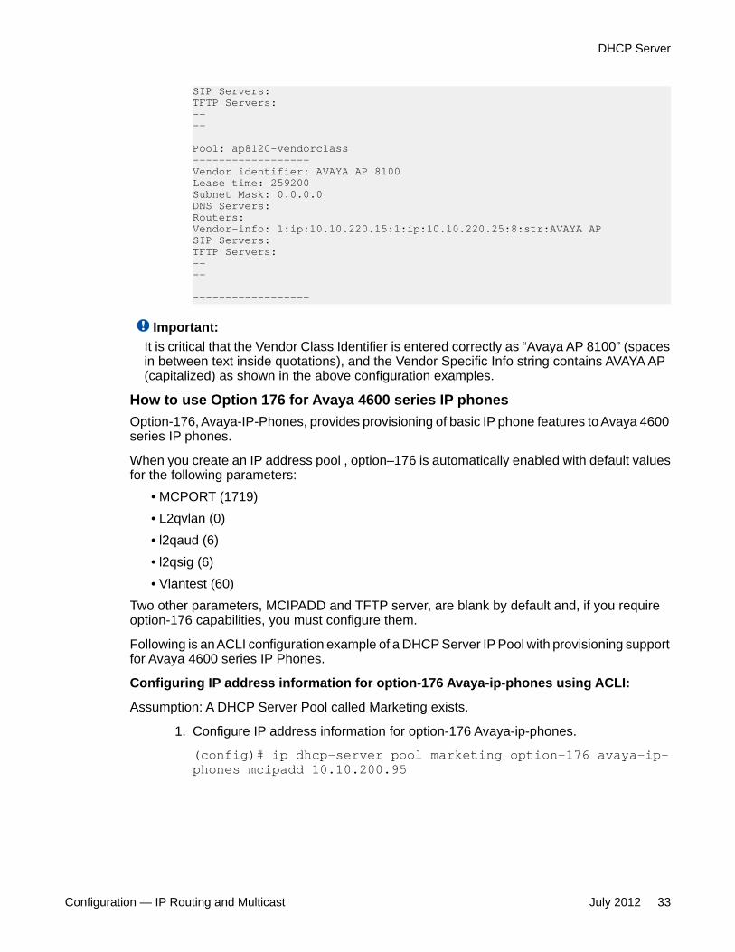
SIP Servers: TFTP Servers: ----
Pool: ap8120-vendorclass------------------Vendor identifier: AVAYA AP 8100 Lease time: 259200 Subnet Mask: 0.0.0.0DNS Servers: Routers:Vendor-info: 1:ip:10.10.220.15:1:ip:10.10.220.25:8:str:AVAYA APSIP Servers: TFTP Servers: ----
------------------
Important:It is critical that the Vendor Class Identifier is entered correctly as “Avaya AP 8100” (spacesin between text inside quotations), and the Vendor Specific Info string contains AVAYA AP(capitalized) as shown in the above configuration examples.
How to use Option 176 for Avaya 4600 series IP phonesOption-176, Avaya-IP-Phones, provides provisioning of basic IP phone features to Avaya 4600series IP phones.
When you create an IP address pool , option–176 is automatically enabled with default valuesfor the following parameters:
• MCPORT (1719)• L2qvlan (0)• l2qaud (6)• l2qsig (6)• Vlantest (60)
Two other parameters, MCIPADD and TFTP server, are blank by default and, if you requireoption-176 capabilities, you must configure them.
Following is an ACLI configuration example of a DHCP Server IP Pool with provisioning supportfor Avaya 4600 series IP Phones.
Configuring IP address information for option-176 Avaya-ip-phones using ACLI:
Assumption: A DHCP Server Pool called Marketing exists.
1. Configure IP address information for option-176 Avaya-ip-phones.
(config)# ip dhcp-server pool marketing option-176 avaya-ip-phones mcipadd 10.10.200.95
DHCP Server
Configuration — IP Routing and Multicast July 2012 33

(config)# ip dhcp-server pool marketing option-176 avaya-ip-phones tftp-servers 10.10.200.98
2. Optional—Change mcport number and L21vlan parameters for option-176 Avaya-ip-phones
(config)# ip dhcp-server pool marketing option-176 avaya-ip-phones mcport 9200(config)# ip dhcp-server pool marketing option-176 avaya-ip-phones lq2vlan 2
3. Display pool configuration for “marketing”.
2500(config)# show ip dhcp-server poolPool: marketingStart IP address: 10.10.10.100End IP address: 10.10.10.199Lease time: 86400Subnet Mask: 255.255.255.0DNS Servers:Routers: 10.10.10.1Vendor-info:SIP Servers:TFTP Servers:Avaya IP-Phones:MCIPADD: 10.10.200.95MCPORT: 9200Tftpsrvr: 10.10.200.98L2qvlan: 2Vlantest: 60L2qaud: 6L2qsig: 6
Configuring IP address information for option-176 Avaya-ip-phones using EDM :
Assumption: A DHCP Server Pool called Marketing exists.
1. On the Configuration tree, click IP.2. On the IP tree, click DHCP Server.3. In the DHCP Server work area, click the DHCP Server Pool tab.
IP routing fundamentals
34 Configuration — IP Routing and Multicast July 2012Comments? [email protected]

4. In the DHCP Server Pool work area, click the Marketing pool row.5. On the toolbar, click Options.6. In the Options dialog, click Insert.7. Select the IP Phone MCIP addr (176) radio button.8. Enter the IP address.9. Click Insert.
If you require a second MC IP addr IP addres value, repeat the preceding steps andinset an additional IP address.
10. In the DHCP Server Pool work area, click the Marketing pool row.11. On the toolbar, click Options.12. Click Insert.13. Select the IP Phone TFTP Server (176) radio button.14. Enter the IP address.15. Click Insert.16. In the DHCP Server Pool work area, double-click the IpPhoneMcport cell so you
can modify it.17. Change the cell value to 9200.18. In the DHCP Server Pool work area, double-click the IpPhoneL2qvlan cell so you
can modify it.19. Change the value to 2.20. On the toolbar, click Apply.
How to use Option 241 for Avaya IP phonesYou can provide Voice VLAN information to Avaya 1100, 1200 and 2000 series IP Phonesusing DHCP options assigned to the data VLAN as well as extended options.
The IP Phone options are defined as a string and contain parameters and values separatedby semicolons. For option 241, only the Nortel specific option of Nortel-i2004–B will besupported. As one or more parameters are defined for this option, they are appended to theNortel-i2004–B specific option. You can also remove specific parameters from an existingstring. When adding or removing parameters, the use of Nortel-i2004–B specific option at thebeginning of the string is optional.
Although all specified parameters are supported, the maximum option length of the Option 241string is 255 characters, The input string for option 241 is validated to verify the parametersfrom the string are valid, however, there is no check for their values, or whether a specificparameter is entered more than once in the same command.
A parameter is considered to be the value between the equals sign and semicolon from theinput string. You will receive an error message if an invalid parameter is found in the inputstring. For a list of the supported parameters, see DHCP Server Option 241 parameters onpage 98.
DHCP Server
Configuration — IP Routing and Multicast July 2012 35
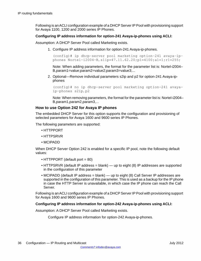
Following is an ACLI configuration example of a DHCP Server IP Pool with provisioning supportfor Avaya 1100, 1200 and 2000 series IP Phones.
Configuring IP address information for option-241 Avaya-ip-phones using ACLI:
Assumption: A DHCP Server Pool called Marketing exists.
1. Configure IP address information for option-241 Avaya-ip-phones.
(config)# ip dhcp-server pool marketing option-241 avaya-ip-phones Nortel-i2004–B,s1ip=47.11.62.20;p1=4100;a1=1;r1=255;Note: When adding parameters, the format for the parameter list is: Nortel-i2004–B,param1=value;param2=value2;param3=value3;...
2. Optional—Remove individual parameters s2ip and p2 for option-241 Avaya-ip-phones
(config)# no ip dhcp-server pool marketing option-241 avaya-ip-phones s2ip,p2Note: When removing parameters, the format for the parameter list is: Nortel-i2004–B,param1,param2,param3,...
How to use Option 242 for Avaya IP phonesThe embedded DHCP Server for this option supports the configuration and provisioning ofselected parameters for Avaya 1600 and 9600 series IP Phones.
The following parameters are supported:• HTTPPORT• HTTPSRVR• MCIPADD
When DHCP Server Option 242 is enabled for a specific IP pool, note the following defaultvalues:
• HTTPPORT (default port = 80)• HTTPSRVR (default IP address = blank) — up to eight (8) IP addresses are supported
in the configuration of this parameter• MCIPADD (default IP address = blank) — up to eight (8) Call Server IP addresses are
supported in the configuration of this parameter. This is used as a backup for the IP phonein case the HTTP Server is unavailable, in which case the IP phone can reach the CallServer.
Following is an ACLI configuration example of a DHCP Server IP Pool with provisioning supportfor Avaya 1600 and 9600 series IP Phones.
Configuring IP address information for option-242 Avaya-ip-phones using ACLI:
Assumption: A DHCP Server Pool called Marketing exists.
Configure IP address information for option-242 Avaya-ip-phones.
IP routing fundamentals
36 Configuration — IP Routing and Multicast July 2012Comments? [email protected]

(config)# ip dhcp-server pool marketing option-242 avaya-ip-phones mcipadd 10.10.200.95(config)# ip dhcp-server pool marketing option-242 avaya-ip-phones httpsrvr 10.10.200.98
Related routing featuresThe following sections describe features that are related to and dependent on the IP routingfunctionality.
BootP/DHCP relayDynamic Host Configuration Protocol (DHCP) is a mechanism to assign network IP addresseson a dynamic basis to clients who request an address. DHCP is an extension of the Bootstrapprotocol (BootP). BootP/DHCP clients (workstations) generally use User Datagram Protocol(UDP) broadcasts to determine their IP addresses and configuration information. If such a hostis on a VLAN that does not include a DHCP server, the UDP broadcasts are by default notforwarded to servers located on different VLANs.
The Avaya Ethernet Routing Switch 2500 Series, can resolve this issue using DHCP relay,which forwards the DHCP broadcasts to the IP address of the DHCP server. Network managersprefer to configure a small number of DHCP servers in a central location to lower administrativeoverhead. Routers must support DHCP relay so that hosts can access configurationinformation from servers several router hops away.
With DHCP relay enabled, the switch can relay client requests to DHCP servers on differentLayer 3 VLANs or in remote networks. It also relays server replies back to the clients.
To relay DHCP messages, you must create two Layer 3 VLANs: one connected to the clientand the other providing a path to the DHCP server. You can enable DHCP relay on a per-VLANbasis.
The following figure shows a DHCP relay example, with an end station connected to subnet1, corresponding to VLAN 1. The Avaya Ethernet Routing Switch 2500 Series, connects twosubnets by means of the virtual routing function. When the end station generates a DHCPrequest as a limited UDP broadcast to the IP address of all 1s (that is, 255.255.255.255), withthe DHCP relay function enabled, the Ethernet Routing Switch forwards the DHCP request tothe host address of the DHCP server on VLAN 2.
Related routing features
Configuration — IP Routing and Multicast July 2012 37

Figure 5: DHCP relay operation
Forwarding DHCP packets
In the following figure, the DHCP relay agent address is 10.10.1.254. To configure the AvayaEthernet Routing Switch 2500 Series,to forward DHCP packets from the end station to theserver, use 10.10.2.1 as the server address.
Figure 6: Forwarding DHCP packets
All BootP and DHCP broadcast packets that appear on the VLAN 1 router interface(10.10.1.254) are then forwarded to the DHCP server. In this case, the DHCP packets areforwarded as unicast to the DHCP server IP address.
IP routing fundamentals
38 Configuration — IP Routing and Multicast July 2012Comments? [email protected]

Multiple DHCP servers
Most enterprise networks use multiple DHCP servers for fault tolerance. The Avaya EthernetRouting Switch 2500 Series, can forward DHCP requests to multiple servers. You can configureup to 256 servers to receive copies of the forwarded DHCP messages.
To configure DHCP client requests to be forwarded to multiple different server IP addresses,specify the client VLAN as the DHCP relay agent for each of the destination server IPaddresses.
In the following figure, two DHCP servers are located on two different VLANs. To configure theAvaya Ethernet Routing Switch 2500 Series, to forward copies of the DHCP packets from theend station to both servers, specify the IP address of VLAN 1 (10.10.1.254) as the DHCP relayagent address and associate this relay agent with each of the DHCP server addresses,10.10.2.1 and 10.10.3.1.
Figure 7: Multiple DHCP servers
Related routing features
Configuration — IP Routing and Multicast July 2012 39
Differences between DHCP and BootP
With DHCP relay, the Avaya Ethernet Routing Switch 2500 Series, supports the relay of DHCPand the Bootstrap protocol (BootP). The following differences between DHCP and BootP arespecified in RFC 2131:
• BootP enables the retrieval of an American Standard Code for Information Interchange(ASCII) configuration file name and configuration server address.
• A properly configured BootP server enables the switch to automatically learn its assignedIP address, subnet mask, and the IP address of the default router (default gateway).
• DHCP defines mechanisms through which clients can be assigned a network address fora finite lease (allowing for reuse of IP addresses).
• DHCP provides the mechanism for clients to acquire all of the IP configuration parametersthey need to operate.
DHCP uses the BootP message format defined in RFC 951. The remainder of the options fieldconsists of a list of tagged parameters that are called options(RFC 2131).
DHCP option 82 supportDHCP option 82 support is an extension of Dynamic Host Configuration Protocol (RFC3046and RFC3993) that enables the switch to send information about DHCP clients to theauthenticating DHCP server. When you enable option 82, in either Layer 2 or Layer 3 mode,the switch inserts additional port-based identification information into the DHCP packetstraversing the switch enroute to the DHCP server. The DHCP server stores this additionalidentification information within the IP allocation record to assist in tracking of end devicelocations; for example, to provide location-based information for emergency servicesapplications.
When a VLAN is operating in Layer 2 mode, DHCP Snooping must be enabled for DHCPOption 82 to function, both globally and on each client VLAN. For more information aboutDHCP Snooping, see Avaya Ethernet Routing Switch 2500 Series Configuration, Security(NN47215-505).
When a VLAN is operating in Layer 3 (IP Routing) mode, the DHCP Option 82 function requiresthat DHCP Relay is appropriately configured. To use DHCP Option 82 with DHCP relay, youmust enable DHCP relay globally on the switch and client VLANs. And you must configure atleast one forward path.
If you configure two DHCP Servers (one in the same VLAN with the DHCP Client and one inanother VLAN) and you enable both DHCP Snoooping Option 82 and DHCP Relay Option 82,the system adds the option for both servers.
DHCP Relay Packet Size
In accordance with RFC3046, you can specify the maximum frame size the DHCP relay agentcan forward to the DHCP server. While the switch implementation permits configuration of the
IP routing fundamentals
40 Configuration — IP Routing and Multicast July 2012Comments? [email protected]

maximum DHCP packet size up to 1536 bytes, the default maximum size is 576 bytes. If theDHCP frame received is larger that the configured frame size, the switch does not relay thepacket. If the DHCP packet exceeds the maximum configured size, the DHCP Option 82information is not appended to the message.
UDP broadcast forwardingBy default, User Datagram Protocol (UDP) broadcast frames received on one VLAN are notrouted to another VLAN. To allow UDP broadcasts to reach a remote server, the EthernetRouting Switch supports UDP broadcast forwarding, which forwards the broadcasts to theserver through a Layer 3 VLAN interface.
UDP broadcast forwarding is a general mechanism for selectively forwarding limited UDPbroadcasts received on an IP interface to a configured IP address. The packet is sent as aunicast packet to the server.
When a UDP broadcast is received on a router interface, it must meet the following criteria tobe considered for forwarding:
• It must be a MAC-level broadcast.• It must be an IP-limited broadcast.• It must be for a configured UDP protocol.• It must have a time-to-live (TTL) value of at least 2.
For each ingress interface and protocol, the UDP broadcast packets are forwarded only to aunicast host address (for example, to the unicast IP address of the server).
When the UDP forwarding feature is enabled, a filter is installed that compares the UDPdestination port of all packets against all the configured UDP forwarding entries. If a matchoccurs, the destination IP of the incoming packet is checked for consistency with the user-configured broadcast mask value for this source VLAN. If these conditions are met, the TTLfield from the incoming packet is overwritten with the user-configured TTL value, the destinationIP of the packet is overwritten with the configured destination IP, and the packet is routed tothe destination as a unicast frame.
UDP forwarding example
Figure 8: UDP forwarding example on page 42 shows an example of UDP broadcastforwarding. In this case, if host A (10.200.1.10) needs a certain service (for example, a customapplication that listens on UDP port 12345), it transmits a UDP broadcast frame. By default,the Ethernet Routing Switch does not forward this frame to VLAN 100, and because server B(10.100.1.10) is not on VLAN 200, the host cannot access that service.
With UDP broadcast forwarding enabled, the host can access the service. In this case, youmust list port 12345 as a valid forwarding port, and specify VLAN 200 as the source VLAN.
Related routing features
Configuration — IP Routing and Multicast July 2012 41

Figure 8: UDP forwarding example
When the switch receives an incoming packet on VLAN 200 that matches the configured UDPdestination port (12345), and the destination IP is consistent with the broadcast mask valuefor the VLAN, then the switch applies the new destination IP (here, 10.100.1.10) to the packetand routes it to the destination as a unicast frame.
Directed broadcasts
With the directed broadcasts feature enabled, the Ethernet Routing Switch can determine ifan incoming unicast frame is a directed broadcast for one of its interfaces. If so, the switchforwards the datagram onto the appropriate network using a link-layer broadcast.
With IP directed broadcasting enabled on a VLAN, the Ethernet Routing Switch forwards directbroadcast packets in the following two ways:
• through a connected VLAN subnet to another connected VLAN subnet
• through a remote VLAN subnet to the connected VLAN subnet
By default, this feature is disabled.
IP routing fundamentals
42 Configuration — IP Routing and Multicast July 2012Comments? [email protected]
ARP
The Address Resolution Protocol (ARP) allows the Ethernet Routing Switch to dynamicallylearn Layer 2 Media Access Control (MAC) addresses, and to build a table with correspondingLayer 3 IP addresses.
Network stations using the IP protocol need both a physical (MAC) address and an IP addressto transmit a packet. If a network station knows only the IP address of a network host, ARPenables the network station to determine the physical address of the network host and bindthe 32-bit IP address to a 48-bit MAC address. A network station can use ARP across a singlenetwork only, and the network hardware must support physical broadcasts.
If a network station wants to send a packet to a host but knows only the host IP address, thenetwork station uses ARP to determine the physical address of the host as follows:
1. The network station broadcasts a special packet, called an ARP request, that asksthe host at the specified IP address to respond with its physical address.
2. All network hosts receive the broadcast message.
3. Only the specified host responds with its hardware address.
4. The network station then maps the host IP address to its physical address and savesthe results in an address resolution table for future use.
5. The network station ARP table displays the association of the known MACaddresses to IP addresses.
The lifetime for the learned MAC addresses is a configurable parameter. The switch executesARP lookups after this timer expires.
The default timeout value for ARP entries is 6 hours.
Static ARP
In addition to the dynamic ARP mechanism, the Ethernet Routing Switch supports a staticmechanism that allows for static ARP entries to be added. With Static ARP, you can manuallyassociate a device MAC address to an IP address. You can add and delete individual staticARP entries on the switch.
Proxy ARP
Proxy ARP allows the Ethernet Routing Switch to respond to an ARP request from a locallyattached host that is intended for a remote destination. It does so by sending an ARP responseback to the local host with the MAC address of the switch interface that is connected to thehost subnet. The reply is generated only if the switch has an active route to the destinationnetwork.
Related routing features
Configuration — IP Routing and Multicast July 2012 43

With Proxy ARP enabled, the connected host can reach remote subnets without the need toconfigure default gateways.
The following figure is an example of proxy ARP operation. In this example, host B wants tosend traffic to host C, so host B sends an ARP request for host C. However, the Avaya EthernetRouting Switch 2500 Series, is between the two hosts, so the ARP message does not reachhost C. To enable communication between the two hosts, the Avaya Ethernet Routing Switch2500 Series, intercepts the message and responds to the ARP request with the IP address ofhost C but with the MAC address of the switch itself. Host B then updates its ARP table withthe received information.
Figure 9: Proxy ARP Operation
Avaya recommends Proxy ARP as a temporary fix only, for example, if you are graduallymoving hosts from one addressing scheme to another and you still want to maintainconnectivity between the disparately-addressed devices. You do not want Proxy ARP runningas a general rule because it causes hosts to generate ARP messages for every address thatthey want to reach on the Internet.
IP blocking for stacks
IP blocking is a Layer 3 feature of the Avaya Ethernet Routing Switch 2500 Series, that providessafeguards for a stack where Layer 3 VLANs have port members across multiple stack units.IP Blocking is used whenever a unit leaves a stack or is rebooting inside the context of a stack.Depending on the setting in use, Layer 3 functionality is either continued or blocked by thisfeature.
You can set the IP Blocking mode on the base unit to either none or full.
When IP blocking is set to full, if any units leave the stack, those units run in Layer 2 mode.No Layer 3 settings remain on the units.
IP routing fundamentals
44 Configuration — IP Routing and Multicast July 2012Comments? [email protected]

When IP blocking is set to none, if any units leave the stack, the Layer 3 configurations appliedto the stack are still applied on the individual units.
In a stack environment of 2 units, Avaya recommends that you use IP blocking mode none. Inthis case, you can expect the following functional characteristics:
• If either the stack base unit or nonbase unit becomes nonoperational, Layer 3 functionalitycontinues to run on the remaining unit.
A disadvantage of this configuration is that if the nonoperational unit does not rejoin the stack,address duplication occurs.
In stack environments of more than 2 units, Avaya recommends that you use IP blocking modefull. In this case, you can expect the following functional characteristics:
• If the stack base unit becomes nonoperational, the following occurs:
- The temporary base unit takes over base unit duties.
- The temporary base unit takes over responsibility to manage Layer 3 functionalityin the stack. When this occurs, the system updates the MAC addresses associatedwith each routing interface to be offset from the temporary base unit MAC address(rather than the base unit MAC address). During this period, some minor disruptionmay occur to routing traffic until end stations update their ARP cache with the newrouter MAC addresses. The Avaya Ethernet Routing Switch 2500 Series, sends outgratuitous ARP messages on each routed VLAN for 5 minutes at 15 second intervalsto facilitate quick failover in this instance.
- If the nonoperational base unit does not rejoin the stack, no Layer 3 functionalityruns on the unit.
• If a stack nonbase unit becomes nonoperational, the following occurs:
- The stack continues to run normally with the base unit controlling Layer 3functionality.
- If the nonoperational nonbase unit does not rejoin the stack, no Layer 3 functionalityruns on the unit.
By default, the IP blocking mode is none (disabled).
Related routing features
Configuration — IP Routing and Multicast July 2012 45

Routing feature capabilities and limitationsThe following list describes the routing feature capabilities and limitations on the EthernetRouting Switch:
• Nonlocal static routes are not available for this release. For a route to become active, thecorresponding next-hop IP address must be reachable through a directly connectedsubnet.
• A maximum of 256 local routes, and up to 32 static routes including the default route(Destination = 0.0.0.0 Mask = 0.0.0.0) are supported.
• The maximum number of management routes is 4.
• The maximum number of dynamic ARP entries is 1000.
• The maximum number of static ARP entries is 256.
• When adding a static ARP entry for a VLAN subnet, the IP address associated with theMAC address must be in the subnet for the VLAN. Otherwise the following error messageis returned:
% Cannot modify settingsIP address does not match with VLAN subnet
• UDP broadcast forwarding supports the following capabilities:
- You can configure a maximum of 128 UDP port/protocol entries.
- You can configure a maximum of 128 UDP forwarding lists.
- You can configure a maximum of 16 ports (with their IP addresses) in one forwardinglist.
- You can bind a maximum of 16 VLANs to the same UDP forwarding list.
IP routing fundamentals
46 Configuration — IP Routing and Multicast July 2012Comments? [email protected]

Chapter 4: IGMP fundamentals
This chapter provides an overview of IP multicast and Internet Group Management Protocol (IGMP). Tosupport multicast traffic, the Avaya Ethernet Routing Switch 2500 Series, provides support for IGMPsnooping.
Overview of IP multicastMost traditional network applications such as Web browsers and e-mail employ unicastconnections in which each client sets up a separate connection to a server to access specificdata. However, with certain applications such as audio and video streaming, more than oneclient accesses the same data at the same time. With these applications, if the server sendsthe same data to each individual client using unicast connections, the multiple connectionswaste both server and network capacity. For example, if a server offers a 1 Mbit/sec live videostream for each client, a 100 Mbit/sec network interface card (NIC) on the server could becompletely saturated after 90 client connections. The following figure shows an example ofthis waste of resources.
Figure 10: Wasteful propagation of multiple copies of the same unicast stream
Multicasting provides the ability to transmit only one stream of data to all the interested clientsat the same time. The following figure shows a simple example of how multicasting works. Thesource of the multicast data forwards only one stream to the nearest downstream router, and
Configuration — IP Routing and Multicast July 2012 47

each subsequent downstream router forwards a copy of the same data stream to the recipientswho are registered to receive it.
Figure 11: One stream replicated using multicasting
This one-to-many delivery mechanism is similar to broadcasting except that, whilebroadcasting transmits to all hosts in a network, multicasting transmits only to registered hostgroups. Because multicast applications transmit only one stream of data, which is thenreplicated to many receivers, multicasting saves a considerable amount of bandwidth.
Clients that want to receive the stream must register with the nearest multicast router tobecome a part of the receiving multicast group.
One downside to multicasting is that the multicast streams transmit data using User DatagramProtocol (UDP) packets, which are not as reliable as Transmission Control Protocol (TCP)packets.
Applications that use multicasting to transmit data include the following:
• multimedia conferencing• real-time data multicasts (such as stock tickers)• gaming and simulations
Multicast groupsTo receive a multicast stream from a particular source, hosts must register with the nearestmulticast router. The router adds all interested hosts to a multicast group, which is identifiedby a multicast IP address.
Multicast routers use Internet Group Membership Protocol (IGMP) to learn the existence ofhost group members on their directly attached subnets. To identify the hosts that want to be
IGMP fundamentals
48 Configuration — IP Routing and Multicast July 2012Comments? [email protected]

added to a group, a querier router sends out IGMP queries to each local network. A host thatwants to belong to the group sends a response in the form of an IGMP membership report.
Each multicast router maintains a multicast routing table that lists each source, group (S,G)pair, which identifies the IP address of the source and the multicast address of the receivinggroup. For each (S,G) pair, the router maintains a list of downstream forwarding ports to whichthe multicast traffic is forwarded, and the upstream port where the multicast traffic isreceived.
Multicast addressesEach multicast host group is assigned a unique multicast address. To reach all members ofthe group, a sender uses the multicast address as the destination address of the datagram.
An IP version 4 multicast address is a Class D address (the high-order bits are set to 1110)from 224.0.1.0 to 239.255.255.255. These addresses are assigned statically for use bypermanent groups and dynamically for use by transient groups.
On the Ethernet Routing Switch 2500 Series, you cannot use 24-bit subnets like 224.0.0.0/24and 224.128.0.0/24 for multicast data traffic. This restriction applies to the entire multicastaddress range from 224.0.0.0/8 to 239.128.0.0/8.
IGMP overviewIGMP is the Layer 3 protocol used by IP multicast routers to learn the existence of multicastgroup members on their directly attached subnets (see RFC 2236). With IGMP, hosts canregister their desired group memberships to their local querier router.
A multicast querier router communicates with hosts on a local network by sending IGMPqueries. The router periodically sends a general query message to each local network of therouter. A host that wants to join a multicast group sends a response in the form of a membershipreport requesting registration with a group. After the querier router registers hosts to a group,it forwards all incoming multicast group packets to the registered host networks. As long asany host on a subnet continues to participate in the group, all hosts, including nonparticipatingend stations on that subnet, receive the IP Multicast stream.
IGMP versions are backward compatible and can all exist together on a multicast network.
The following sections provide more details about the differences between the different IGMPversions.
IGMPv1 operationIGMP version 1 is the simplest of the IGMP versions and is widely deployed.
IGMP overview
Configuration — IP Routing and Multicast July 2012 49
IGMPv1 supports the following two message types:
• 0x11 – Membership Query message. Packets are sent to the all-systems multicast group(224.0.0.1).
• 0x12 – Membership Report message. Packets are sent to the group that the host intendsto join.
The IGMPv1 router periodically sends host membership queries (also known as generalqueries) to its attached local subnets to inquire if any hosts are interested in joining anymulticast groups. The interval between queries is a configurable value on the router. A hostthat wants to join a multicast group sends a membership report message to the nearest router,one report for each joined multicast group. After receiving the report, the router adds theMulticast IP address and the host port to its forwarding table. The router then forwards anymulticast traffic for that multicast IP address to all member ports.
The router keeps a list of multicast group memberships for each attached network, and a GroupMembership Interval timer for each membership. Repeated IGMP membership reports refreshthe timer. If no reports are received before the timer expires, the router sends a querymessage.
In some cases, the host does not wait for a query before it sends report messages to the router.Upon initialization, the host can immediately issue a report for each of the multicast groupsthat it supports. The router accepts and processes these asynchronous reports the same wayit accepts requested reports.
IGMPv1 leave process
After hosts and routers are in a steady state, they communicate in a way that minimizes theexchange of queries and reports. The designated routers set up a path between the IPMulticast stream source and the end stations, and periodically query the end stations todetermine whether they want to continue to participate. As long as any host on the subnetcontinues to participate, all hosts, including nonparticipating end stations on the subnet,receive the IP Multicast stream.
If all hosts on the subnet leave the group, the router continues to send general queries to thesubnet. If no hosts send reports after three consecutive queries, the router determines that nogroup members are present on the subnet.
IGMPv2 operationIGMPv2 extends the IGMPv1 features by implementing a host leave message to quickly reportgroup membership termination to the routing protocol. Instead of routers sending multiplequeries before determining that hosts have left a group, the hosts can send a leave message.This feature is important for multicast groups with highly volatile group membership.
The IGMPv2 join process is similar to the IGMPv1 join process.
IGMPv2 also implements a querier election process.
IGMP fundamentals
50 Configuration — IP Routing and Multicast July 2012Comments? [email protected]

IGMPv2 adds support for the following three new message types:
• 0x11 – General Query and Group Specific Query message.• 0x16 – Version 2 Membership Report (sent to the destination IP address of the group
being reported)• 0x17 – Version 2 Membership Leave message (sent to all-router [224.0.0.2] multicast
address)IGMPv2 also supports IGMPv1 messages.
Host leave process
With IGMPv2, if the host that issued the most recent report leaves a group, the host issues aleave message. The multicast router on the network then issues a group-specific query todetermine whether other group members are present on the network. In the group-specificquery message, the Group Address field is the group being queried (the Group Address fieldis 0 for the General Query message). If no host responds to the query, the router determinesthat no members belonging to that group exist on that interface.
The following figure shows an example of how IGMPv2 works.
Figure 12: IGMPv2
In this example, the following occurs:
• The host sends a leave message (to 224.0.0.2).
• The router sends a group-specific query to group 239.1.1.1.
• No IGMP report is received.
• Group 239.1.1.1 times out.
Querier election process
Normally only one querier exists for each subnet. When multiple IGMPv2 routers are presenton a network, the router with the lowest IP address is elected to send queries. All multicastrouters start up as a querier on each attached network. If a multicast router receives a query
IGMP overview
Configuration — IP Routing and Multicast July 2012 51

message from a router with a lower IP address, the router with the higher IP address becomesa nonquerier on that network.
IGMPv3 operationIGMPv3 adds support for source filtering. The IGMPv3 host can report its interest in receivingmulticast packets from only specific source addresses, or the host can report its interest inreceiving multicast packets from all but specific source addresses.
IGMPv3 is mostly used in voice and video conferences where multiple people can be part ofthe same conference. The IGMPv3 packet format adds a v3 Report message type (0x22) andincludes Source-and-Group-specific Query messages.
The message type for Source-and-Group-specific Query message is 0x11, the same asIGMPv1 and IGMPv2. The different Query message versions are identified as follows:
• If the size of the IGMP message type is 8, then it is a v1 or v2 Query message.• If the Group Address field is 0, then it is a General Query.• If the Group Address field is a valid multicast IP address, then it is a Group-specific
Query.• If the Group Address field is a valid address and the Number of Sources field is nonzero,
then it is a Group-and-Source specific Query message.Each IGMPv3 Report contains a list of group records. The Group Record contains the multicastgroup address and the list of source addresses. The record type field specifies whether toINCLUDE or EXCLUDE the list of source addresses that are provided in the Source Addressfield. For example, to include packets from source 10.10.10.1, the report contains anINCLUDE(10.10.10.1) record.
The list of source addresses can be empty, which is represented by braces ({}), which meanseither to INCLUDE or EXCLUDE none. For example, the host that wants to receive packetsfrom all group members can send a report with an EXCLUDE({}) record and a host that wantsto leave a group can send a report with an INCLUDE({}) record, which is similar to a leavemessage.
In the following figure, hosts A, B, C, D, E, and F are part of a conference group G1. All hostsexcept F send a report for group G1 with the mode as INCLUDE(A, B, C, D, E, F) containingall the source addresses. Host F, which is not interested in listening to C and D, sends a reportto group G1 with the mode as EXCLUDE(C, D).
IGMP fundamentals
52 Configuration — IP Routing and Multicast July 2012Comments? [email protected]

Figure 13: IGMPv3
The router adds the multicast IP address and the list of sources in the forwarding table. Therouter forwards the packets from A, B, E, and F to all ports. If the packets are received from Cand D, it is forwarded to all ports except port 11.
IGMP requests for commentFor additional information about IGMP, see the following requests for comment (RFC):
• For IGMPv1, see RFC 1112.
• For IGMPv2, see RFC 2236.
• For IGMPv3, see RFC 3376
• For IGMP snooping, see RFC 4541.
• For IGMP management information bases (MIB), see RFC 2933.
IGMP snoopingIf at least one host on a VLAN specifies that it is a member of a group, by default, the AvayaEthernet Routing Switch 2500 Series, forwards to that VLAN all datagrams bearing themulticast address of that group. All ports on the VLAN receive the traffic for that group.
The following figure shows an example of this scenario. Here, the IGMP source provides anIP Multicast stream to a designated router. Because the local network contains receivers, thedesignated router forwards the IP Multicast stream to the network. Switches without IGMPsnoop enabled flood the IP Multicast traffic to all segments on the local subnet. The receiversrequesting the traffic receive the desired stream, but so do all other hosts on the network.
IGMP snooping
Configuration — IP Routing and Multicast July 2012 53

Although the nonparticipating end stations can filter the IP Multicast traffic, the IP Multicasttraffic still exists on the subnet and consumes bandwidth.
Figure 14: IP multicast propagation on a LAN without IGMP snooping
To prune ports that are not group members from receiving the group data, the Avaya EthernetRouting Switch 2500 Series supports IGMP snoop for IGMPv1, IGMPv2, and IGMPv3. WithIGMP snoop enabled on a VLAN, the switch forwards the multicast group data to only thoseports that are members of the group. When using IGMP snoop, VLANs can provide the samebenefit as IP Multicast routers, but in the local area.
The Avaya Ethernet Routing Switch 2500 Series, identifies multicast group members bylistening to IGMP packets (IGMP reports, leaves, and queries) from each port. The switchsuppresses the reports by not forwarding them out to other VLAN ports, forcing the membersto continuously send their own reports. The switch uses the information gathered from thereports to build a list of group members. After the group members are identified, the switchblocks the IP Multicast stream from exiting any port that does not connect to a group member,thus conserving bandwidth.
As shown in the following figure, after the switches learn which ports are requesting access tothe IP Multicast stream, all other ports not responding to the queries are blocked from receivingthe IP Multicast data.
IGMP fundamentals
54 Configuration — IP Routing and Multicast July 2012Comments? [email protected]

Figure 15: Ethernet Routing Switch running IGMP snooping
The switch continues to forward the IGMP membership reports from the hosts to the multicastrouters, and forwards queries from multicast routers to all port members of the VLAN.
IGMPv3 snoopingIn IGMPv3 snooping mode, the switch recognizes IGMPv3 reports and queries and can:
• recognize whether a source list is populated or blank• identify the specific sources to filter• understand and process all IGMPv3 record type
The following are supported:• source filtering (INCLUDE, EXCLUDE, ALLOW, BLOCK of multicast sources)• SSM (Source Specific Multicast)
The following table shows how IGMPv3 snooping handles different record types.
IGMP snooping
Configuration — IP Routing and Multicast July 2012 55

Table 3: IGMPv3 snooping with record types
IGMP v3 record type Without multicastsource ({ })
Action With multicastsource(s) ({S1,
S2...})
Action
MODE_IS_INCLUDE(1)
This is INCLUDENONE.
LEAVEthegroup.
This isINCLUDEmulticastsources.
JOIN thegroup. Discardmulticastsourceinformation.
MODE_IS_EXCLUDE(2)
This is EXCLUDENONE.
JOIN thegroup.
This isEXCLUDEsources.
JOIN thegroup. Discardmulticastsourceinformation.
CHANGE_TO_INCLUDE_MODE (3)
This is includefilter mode formulticast group.
LEAVEthe group
This is includefilter mode formulticastgroup.
JOIN thegroup. Discardmulticastsourceinformation.
CHANGE_TO_EXCLUDE_MODE (4)
This is excludefilter mode formulticast group.
JOIN thegroup.
This is excludefilter mode formulticastgroup.
JOIN thegroup. Discardmulticastsourceinformation.
ALLOW_NEW_SOURCES (5)
This type is forallowing newsources. Thisrecord type comeswith sources.(This case maynot happen.)
JOIN thegroup.
This type is forallowing newsources.
JOIN thegroup. Discardmulticastsourceinformation.
BLOCK_OLD_SOURCES (6)
This type is forblocking existingsources.
JOIN thegroup.
This type is forblockingexistingsources.
LEAVE thegroup. Discardmulticastsourceinformation.
IGMP proxyWith IGMP snoop enabled, the switch can receive multiple reports for the same multicastgroup. Rather than forward each report upstream, the Ethernet Routing Switch 2500 Seriescan consolidate these multiple reports by using the IGMP proxy feature. With IGMP proxyenabled, if the switch receives multiple reports for the same multicast group, it does not transmiteach report to the upstream multicast router. Instead, the switch forwards the first report to the
IGMP fundamentals
56 Configuration — IP Routing and Multicast July 2012Comments? [email protected]

querier and suppresses the rest. If new information emerges that another multicast group isadded or that a query is received because the last report is transmitted upstream, the reportis then forwarded to the multicast router ports.
To enable IGMP Proxy, you must first activate IGMP snooping.
In Figure 16: Ethernet Routing Switch running IGMP proxy on page 57, switches S1 to S4represent a local area network (LAN) connected to an IP Multicast router. The routerperiodically sends Host Membership Queries to the LAN and listens for a response from endstations. All of the clients connected to switches S1 to S4 are aware of the queries from therouter.
One client, connected to S2, responds with a host membership report. Switch S2 interceptsthe report from that port, and generates a proxy report to its upstream neighbor, S1. Also, twoclients connected to S4 respond with host membership reports, causing S4 to intercept thereports and to generate a consolidated proxy report to its upstream neighbor, S1.
Figure 16: Ethernet Routing Switch running IGMP proxy
Switch S1 treats the consolidated proxy reports from S2 and S4 as if they were reports fromany client connected to its ports, and generates a consolidated proxy report to the designatedrouter. In this scenario, the router receives a single consolidated report from that entiresubnet.
The consolidated proxy report generated by the switch remains transparent to Layer 3 of theInternational Standardization Organization, Open Systems Interconnection (ISO/OSI) model.(The switch IP address and Media Access Control [MAC] address are not part of proxy report
IGMP snooping
Configuration — IP Routing and Multicast July 2012 57

generation.) The last reporting IGMP group member in each VLAN represents all of the hostsin that VLAN and IGMP group.
IGMPv3 proxyWith IGMPv3 proxy enabled, if the switch receives multiple reports for the same multicastgroup, it does not transmit each report to the upstream multicast router. Instead, the switchforwards the first report to the querier and suppresses the rest.
If new information emerges, for example if the switch adds another multicast group or receivesa query since the last report was transmitted upstream, then the switch forwards a new reportto the multicast router ports.
Forwarding of reportsWhen forwarding IGMP membership reports from group members, the Ethernet RoutingSwitch 2500 Series forwards the reports only to those ports where multicast routers areattached. To do this, the switch maintains a list of multicast querier routers and the multicastrouter (mrouter) ports on which they are attached. The switch learns of the multicast querierrouters by listening to the queries sent by the routers where source address is not 0.0.0.0.
Static mrouter port and nonquerierIf two IGMP routers are active on a VLAN, the router with the lower IP address is the querier,and the router with the higher IP address operates as a nonquerier. Only querier routersforward IGMP queries on the VLAN; nonqueriers do not forward IGMP queries. IGMP snoopconsiders the port on which the IGMP query is received as the active IGMP multicast router(mrouter) port. IGMP snoop is not aware of nonquerier IGMP routers.
By default, IGMP snoop forwards reports to the IGMP querier router only. To allow the switchto forward reports to the nonquerier router as well, you can configure the port connected to thenonquerier as a static mrouter port.
Figure 17: Static mrouter port and nonquerier on page 59 shows how static mrouter portsoperate. In this case, the Ethernet Routing Switch 2500 Series has port members 5/1 and 6/1connected to IGMP routers in VLAN 10. Router 1 is the IGMP querier because it has a lowerIP address than router 2. Router 2 is then considered the nonquerier.
By default, the switch learns of the multicast querier routers by listening to the IGMP queries.In this case, port 6/1 connected to querier router 1 is identified as an mrouter port.
To forward reports to IGMP router 2 as well, you can configure port 5/1 on the switch as a staticmrouter port. In this case, the IGMP reports are forwarded to both routers.
IGMP fundamentals
58 Configuration — IP Routing and Multicast July 2012Comments? [email protected]
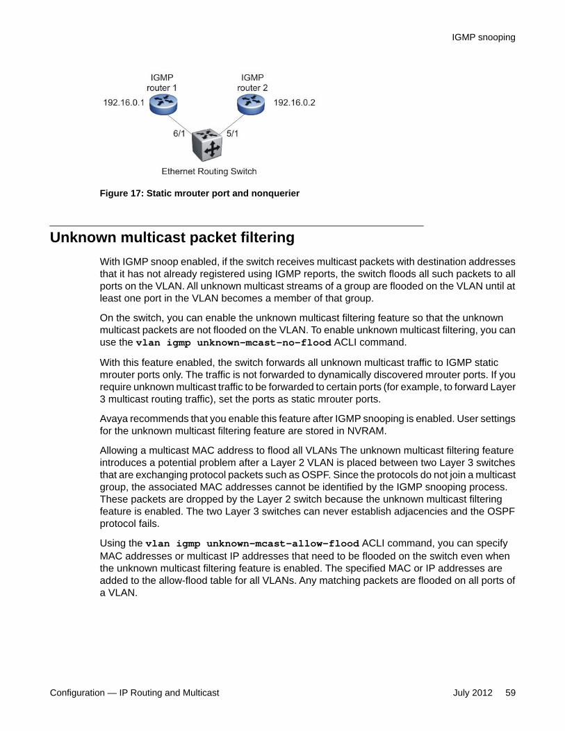
Figure 17: Static mrouter port and nonquerier
Unknown multicast packet filteringWith IGMP snoop enabled, if the switch receives multicast packets with destination addressesthat it has not already registered using IGMP reports, the switch floods all such packets to allports on the VLAN. All unknown multicast streams of a group are flooded on the VLAN until atleast one port in the VLAN becomes a member of that group.
On the switch, you can enable the unknown multicast filtering feature so that the unknownmulticast packets are not flooded on the VLAN. To enable unknown multicast filtering, you canuse the vlan igmp unknown-mcast-no-flood ACLI command.
With this feature enabled, the switch forwards all unknown multicast traffic to IGMP staticmrouter ports only. The traffic is not forwarded to dynamically discovered mrouter ports. If yourequire unknown multicast traffic to be forwarded to certain ports (for example, to forward Layer3 multicast routing traffic), set the ports as static mrouter ports.
Avaya recommends that you enable this feature after IGMP snooping is enabled. User settingsfor the unknown multicast filtering feature are stored in NVRAM.
Allowing a multicast MAC address to flood all VLANs The unknown multicast filtering featureintroduces a potential problem after a Layer 2 VLAN is placed between two Layer 3 switchesthat are exchanging protocol packets such as OSPF. Since the protocols do not join a multicastgroup, the associated MAC addresses cannot be identified by the IGMP snooping process.These packets are dropped by the Layer 2 switch because the unknown multicast filteringfeature is enabled. The two Layer 3 switches can never establish adjacencies and the OSPFprotocol fails.
Using the vlan igmp unknown-mcast-allow-flood ACLI command, you can specifyMAC addresses or multicast IP addresses that need to be flooded on the switch even whenthe unknown multicast filtering feature is enabled. The specified MAC or IP addresses areadded to the allow-flood table for all VLANs. Any matching packets are flooded on all ports ofa VLAN.
IGMP snooping
Configuration — IP Routing and Multicast July 2012 59

Robustness valueAs part of the IGMP snooping configuration, use the robustness value to configure the switchto offset expected packet loss on a subnet. If you expect a network to lose query packets,increase the robustness value.
This value is equal to the number of expected query packet losses for each query interval, plus1. The range is from 2 to 255, and the default is 2. The default value of 2 means that one queryfor each query interval can be dropped without the querier aging out.
IGMP snooping configuration rulesThe IGMP snooping feature operates according to specific configuration rules. Whenconfiguring your switch for IGMP snooping, consider the following rules that determine howthe configuration reacts in any network topology:
• The switch supports up to 240 multicast groups.
If the multicast group table reaches its limit, a new entry cannot be added with a JOINmessage or a new sender identifying a new group. The multicast stream from the newsender is discarded by the hardware. New entries can be added again when the table isnot full.
• You cannot configure port mirroring on a static mrouter port.
• If you configure a Multi-Link Trunk member as a static mrouter port, all the Multi-Link Trunkmembers become static mrouter ports. Also, if you remove a static mrouter port that is aMulti-Link Trunk member, all Multi-Link Trunk members are automatically removed asstatic mrouter port members.
• When you specify MAC or IP addresses to be flooded on the switch, the specifiedaddresses are flooded only on the VLAN specified within the ACLI command. This way,you can flood MAC or IP addresses for specific VLANs only.
• Static mrouter ports must be port members of at least one VLAN.
• If you configure a port as a static mrouter port, it is configured as a static mrouter port forall VLANs on that port. The IGMP configuration is propagated through all VLANs of thatport.
• If you remove a static mrouter port, the membership for that port is removed from allVLANs of that port.
• When Spanning Tree is enabled, the switch learns IGMP groups only on ports that arenot in Listening or Blocking Spanning Tree states (or, when in RSTP/MSTP mode, onlyon ports that are in the Designated state). The switch also learns the groups if STP isdisabled on a port.
IGMP fundamentals
60 Configuration — IP Routing and Multicast July 2012Comments? [email protected]

• The IGMP snooping feature is not Rate Limiting-dependent.
• You must enable the IGMP snooping feature before you can enable the IGMP proxyfeature.
• You can specify static mrouter ports per VLAN.
Important:Because IGMP snooping is set up per VLAN, all IGMP changes are implemented accordingto the VLAN configuration for the specified ports.
Default IGMP valuesThe following table lists the default IGMP values on the Ethernet Routing Switch.
Table 4: Default IGMP values
Parameters Range Default ValueSnooping Enable/Disable Disable
Version 1-3 2
Proxy Enable/Disable Disable
Query Interval 0-65535 125
Robustness Value 2-255 2
IGMP snooping interworking with Windows clientsThis section describes an interworking issue between Windows clients and the EthernetRouting Switches when IGMP snoop is enabled for multicast traffic.
Under normal IGMP snoop operation, as soon as a client joins a specific multicast group, thegroup is no longer unknown to the switch, and the switch sends the multicast stream only tothe ports which request it.
To force a Windows client to only use IGMPv1 or IGMPv2 reports, change the TCP/IP settingsin the Windows Registry located under the following registry key:
Note:ERS2500 Release 4.4 now supports IGMPv3, and therefore, these settings are onlyrequired if you are using IGMPv1, or IGMPv2.
HKEY_LOCAL_MACHINE\SYSTEM\CurrentControlSet\Services
IGMP snooping
Configuration — IP Routing and Multicast July 2012 61

\Tcpip\Parameters
The specific parameter which controls the IGMP Version is:
IGMPVersionKey: Tcpip\ParametersValue Type: REG_DWORD—NumberValid Range: 2, 3, 4Default: 4
To set the Windows Client to only utilize IGMPv2, change the IGMPVersion parameter to 3 (2specifies IGMPv1, 3 specifies IGMPv2, and 4 specifies IGMPv3).
The IGMPVersion parameter may not be present in the list of the TCP/IP parameters. Bydefault, the system assumes the IGMPv3 value (4). To configure the system for IGMPv2, createthe parameter as a DWORD key in the registry and specify Decimal 3.
Important:If you edit the Windows registry incorrectly, you can severely damage your system. As aminimal safeguard, back up your system data before undertaking changes to the registry.
IGMP fundamentals
62 Configuration — IP Routing and Multicast July 2012Comments? [email protected]

Chapter 5: IP routing configuration usingACLI
This chapter describes the procedures you can use to configure routable VLANs using the ACLI.
The Avaya Ethernet Routing Switch 2500 Series, are Layer 3 switches. This means that a regular Layer2 VLAN becomes a routable Layer 3 VLAN if an IP address is attached to the VLAN. When routing isenabled in Layer 3 mode, every Layer 3 VLAN is capable of routing and carrying the management traffic.You can use any Layer 3 VLAN instead of the Management VLAN to manage the switch.
For more information about creating and configuring VLANs, see Configuration—VLANs, Spanning Tree,and Link Aggregation (NN47215-501).
IP routing configuration proceduresTo configure inter-VLAN routing on the switch, perform the following steps:
1. Enable IP routing globally.
2. Assign IP addresses to multiple VLANs.
Routing is automatically enabled on the VLAN after you assign an IP address toit.
In the preceding procedure, you are not required to enable IP routing as the first step. You canconfigure all IP routing parameters on the Avaya Ethernet Routing Switch 2500 Series, beforeyou enable routing on the switch.
Configuring global IP routing statusUse this procedure to enable and disable global routing at the switch level. By default, routingis disabled.
Procedure steps
To configure the status of IP routing on the switch, enter the following from the GlobalConfiguration mode:
Configuration — IP Routing and Multicast July 2012 63

[no] ip routing
Variable definitionsThe following table describes the ip routing command variables.
Variable Valueno Disables IP routing on the switch.
Displaying global IP routing statusUse this procedure to display the status of IP routing on the switch.
Procedure steps
To display the status of IP routing on the switch, enter the following from the User EXECmode:
show ip routing
Configuring an IP address for a VLANTo enable routing an a VLAN, you must first configure an IP address on the VLAN.
Procedure steps
To configure an IP address on a VLAN, enter the following from the VLAN InterfaceConfiguration mode:
[no] ip address <ipaddr> <mask> [<MAC-offset>]
Variable definitionsThe following table describes the ip address command variables.
IP routing configuration using ACLI
64 Configuration — IP Routing and Multicast July 2012Comments? [email protected]

Variable Value
[no] Removes the configured IP address and disables routing on theVLAN.
<ipaddr> Specifies the IP address to attach to the VLAN.
<mask> Specifies the subnet mask to attach to the VLAN
[<MAC-offset>] Specifies the value used to calculate the VLAN MAC address,which is offset from the switch MAC address. The valid range is1-256. Specify the value 1 for the Management VLAN only. If noMAC offset is specified, the switch applies one automatically.
Configuring IP routing status on a VLANUse this procedure to enable and disable routing for a particular VLAN.
Procedure steps
To configure the status of IP routing on a VLAN, enter the following from the VLANInterface Configuration mode:
[default] [no] ip routing
Variable definitionsThe following table describes the ip routing command variables.
Variable Valuedefault Disables IP routing on the VLAN.
no Disables IP routing on the VLAN.
Displaying the IP address configuration and routing statusfor a VLAN
Use this procedure to display the IP address configuration and the status of routing on aVLAN.
Configuring IP routing status on a VLAN
Configuration — IP Routing and Multicast July 2012 65

Procedure steps
To display the IP address configuration on a VLAN, enter the following from thePrivileged Exec mode:
show vlan ip [vid <vid>]
Variable definitionsThe following table describes the show vlan ip command variables.
Variable Value
[vid <vid>] Specifies the VLAN ID of the VLAN to be displayed. Range is1-4094.
Job aidThe following table shows the field descriptions for the show vlan ip command.
Field DescriptionVid Specifies the VLAN ID.
ifIndex Specifies an Index entry for the interface.
Address Specifies the IP address associated with the VLAN.
Mask Specifies the mask.
MacAddress Specifies the MAC address associated with the VLAN.
Offset Specifies the value used to calculate the VLAN MAC address,which is offset from the switch MAC address.
Routing Specifies the status of routing on the VLAN: enabled ordisabled.
Displaying IP routesUse this procedure to display all active routes on the switch.
IP routing configuration using ACLI
66 Configuration — IP Routing and Multicast July 2012Comments? [email protected]

Procedure steps
To display IP routes, enter the following from the User EXEC command mode:
show ip route [<dest-ip>] [-s <subnet> <mask>]
Variable definitionsThe following table describes the show ip route command variables.
Variable Value<dest-ip> Specifies the destination IP address of the routes to display.
[-s <subnet> <mask>] Specifies the destination subnet of the routes to display.
Job aidThe following table shows the field descriptions for the show ip route command.
Field DescriptionDST Identifies the route destination.
MASK Identifies the route mask.
NEXT Identifies the next hop in the route.
COST Identifies the route cost.
VLAN Identifies the VLAN ID on the route.
PORT Specifies the ports.
PROT Specifies the routing protocols. For this release, options are LOC(local route) or STAT (static route).
TYPE Indicates the type of route as described by the Type Legend inthe ACLI command display.
PRF Specifies the route preference.
Displaying IP routes
Configuration — IP Routing and Multicast July 2012 67

IP routing configuration using ACLI
68 Configuration — IP Routing and Multicast July 2012Comments? [email protected]
Chapter 6: Static route configuration usingACLI
This chapter describes the procedures you can use to configure static routes using the ACLI.
Configuring a static routeCreate static routes to manually configure a path to destination IP address prefixes.
Prerequisites
• Enable IP routing globally.
• Enable IP routing and configure an IP address on the VLANs to be routed.
Procedure steps
To configure a static route, enter the following from the Global Configuration commandmode:
[no] ip route <dest-ip> <mask> <next-hop> [<cost>] [disable][enable] [weight <cost>]
Variable definitionsThe following table describes the ip route command variables.
Variable Value[no] Removes the specified static route.
<dest-ip> Specifies the destination IP address for the route being added.0.0.0.0 is considered the default route.
<mask> Specifies the destination subnet mask for the route beingadded.
Configuration — IP Routing and Multicast July 2012 69

Variable Value<next-hop> Specifies the next hop IP address for the route being added.
[<cost>] Specifies the weight, or cost, of the route being added. Range is1-65535.
[enable] Enables the specified static route.
[disable] Disables the specified static route.
[weight <cost>] Changes the weight, or cost, of an existing static route. Range is1-65535.
Displaying static routesUse this procedure to display all static routes, whether these routes are active or inactive.
Procedure steps
To display a static route, enter the following from the User EXEC command mode:
show ip route static [<dest-ip>] [-s <subnet> <mask>]
Variable definitionsThe following table describes the show ip route static command variables.
Variable Value<dest-ip> Specifies the destination IP address of the static routes to
display.
[-s <subnet> <mask>] Specifies the destination subnet of the routes to display.
Job aidThe following table shows the field descriptions for the show ip route staticcommand.
Field DescriptionDST Identifies the route destination.
Static route configuration using ACLI
70 Configuration — IP Routing and Multicast July 2012Comments? [email protected]

Field DescriptionMASK Identifies the route mask.
NEXT Identifies the next hop in the route.
COST Identifies the route cost.
PREF Specifies the route preference.
LCLNHOP Specifies the local next hop status.
STATUS Specifies the static route status. Options are ACTIVE (in use andpresent in routing table) or INACTV (not in use and not presentin routing table).
ENABLE Specifies the administrative state of the static route. Options areTRUE (administratively enabled) or FALSE (administrativelydisabled).
Configuring a management routeUse this procedure to create a management route to the far end network, with a next-hop IPaddress from the management VLAN’s subnet. You can configure a maximum of fourmanagement routes on the switch.
Prerequisites
• Enable IP routing globally.
• Enable IP routing and configure an IP address on the management VLAN interface.
Procedure steps
To configure a static management route, enter the following from the GlobalConfiguration command mode:
[no] ip mgmt route <dest-ip> <mask> <next-hop>
Variable definitionsThe following table describes the ip mgmt route command variables.
Configuring a management route
Configuration — IP Routing and Multicast July 2012 71

Variable Value[no] Removes the specified management route.
<dest-ip> Specifies the destination IP address for the route being added.
<mask> Specifies the destination subnet mask for the route beingadded.
<next-hop> Specifies the next hop IP address for the route being added.
Displaying the management routesUse this procedure to display the static routes configured for the management VLAN.
Procedure steps
To display the static routes configured for the management VLAN, enter the followingfrom the User EXEC mode:
show ip mgmt route
Job aidThe following table shows the field descriptions for the show ip mgmt route command.
Field DescriptionDestination IP Identifies the route destination.
Subnet Mask Identifies the route mask.
Gateway IP Identifies the next hop in the route.
Static route configuration using ACLI
72 Configuration — IP Routing and Multicast July 2012Comments? [email protected]

Chapter 7: DHCP relay configuration usingACLI
This chapter describes the procedures you can use to configure Dynamic Host Configuration Protocol(DHCP) relay using the ACLI.
Important:DHCP relay uses a hardware resource that is shared by switch Quality of Service applications. WhenDHCP relay is enabled globally, the Quality of Service filter manager will not be able to use precedence11 for configurations. For the filter manager to be able to use this resource, DHCP relay must be disabledfor the entire unit or stack.
Prerequisites to DHCP relay configuration using ACLI• Enable IP routing globally.
• Enable IP routing and configure an IP address on the VLAN to be set as the DHCP relayagent.
• Ensure that a route (local or static) to the destination DHCP server is available on theswitch.
DHCP relay configuration proceduresTo configure DHCP relay, perform the following steps:
1. Ensure that DHCP relay is enabled globally. (DHCP relay is enabled by default.)
2. Configure the DHCP relay forwarding path by specifying a local VLAN as the DHCPrelay agent and the remote DHCP server as the destination.
3. Enable DHCP relay for the specific VLAN.
Configuration — IP Routing and Multicast July 2012 73

Enabling global DHCP relayUse the following procedure to enable global DHCP relay. DHCP relay is enabled by default.
Prerequisites
• Access ACLI Global configuration mode
Procedure steps
To enable the global DHCP relay, use the following command:
ip dhcp-relay
Disabling global DHCP relayUse the following procedure to disable global DHCP relay. DHCP relay is enabled bydefault.
Prerequisites
• Access ACLI Global configuration mode
Procedure steps
To disable the global DHCP relay, use the following command:
DHCP relay configuration using ACLI
74 Configuration — IP Routing and Multicast July 2012Comments? [email protected]

no ip dhcp-relay
Setting global DHCP relay to defaultUse the following procedure to set DHCP relay to default settings for the switch. DHCP relayis enabled by default.
Prerequisites
• Access ACLI Global configuration mode
Procedure steps
To set DHCP relay to default, use the following command:
default ip dhcp-relay
Displaying the global DHCP relay statusUse this procedure to display the current DHCP relay status for the switch.
Procedure steps
To display the global DHCP relay status, enter the following from the User EXECcommand mode:
show ip dhcp-relay
Variable definitionsThe following table describes the ip dhcp-relay command variables.
Variable Valuedefault Sets DHCP relay to default settings.
Setting global DHCP relay to default
Configuration — IP Routing and Multicast July 2012 75

Variable Valueno Disables DHCP relay.
show Shows the status of the DHCP relay.
Displaying IP DHCP client parametersUse the following procedure to display IP DCHP client parameters for the switch.
Prerequisites
• Access ACLI Global configuration mode
Procedure steps
To display IP DHCP client paramters, use the following command:
show ip dhcp client lease
Specifying a local DHCP relay agent and remote DHCPserver
Use this procedure to specify a local VLAN as a DHCP relay agent on the forwarding path toa remote DHCP server. The DHCP relay agent can forward DHCP client requests from thelocal network to the DHCP server in the remote network.
The DHCP relay feature is enabled by default, and the default mode is BootP-DHCP.
Procedure steps
To configure a VLAN as a DHCP relay agent, enter the following from the GlobalConfiguration mode:
DHCP relay configuration using ACLI
76 Configuration — IP Routing and Multicast July 2012Comments? [email protected]

[no] ip dhcp-relay fwd-path <relay-agent-ip> <DHCP-server>[enable] [disable] [mode {bootp | bootp-dhcp | dhcp}]
Variable definitionsThe following table describes the ip dhcp-relay fwd-path command variables.
Variable Value[no] Removes the specified DHCP forwarding path.
<relay-agent-ip> Specifies the IP address of the VLAN that serves as the localDHCP relay agent.
<DHCP-server> Specifies the address of the remote DHCP server to whichDHCP packets are to be relayed.
[enable] Enables the specified DHCP relay forwarding path.
[disable] Disables the specified DHCP relay forwarding path.
[mode {bootp |bootp-dhcp |dhcp}]
Specifies the DHCP relay mode:
• BootP only
• BootP and DHCP
• DHCP only
If you do not specify a mode, the default DHCP and BootP isused.
Displaying the DHCP relay configurationUse this procedure to display the current DHCP relay agent configuration.
Procedure steps
To display the DHCP relay configuration, enter the following from the User EXECcommand mode:
Displaying the DHCP relay configuration
Configuration — IP Routing and Multicast July 2012 77

show ip dhcp-relay fwd-path
Job aidThe following table shows the field descriptions for the show ip dhcp-relay fwd-pathcommand.
Field DescriptionINTERFACE Specifies the interface IP address of the DHCP relay agent.
SERVER Specifies the IP address of the DHCP server.
ENABLE Specifies whether DHCP is enabled.
MODE Specifies the DHCP mode.
Configuring DHCP relay on a VLANUse this procedure to configure the DHCP relay parameters on a VLAN. To enable DHCP relayon the VLAN, enter the command with no optional parameters.
Prerequisites
• Access ACLI VLAN Interface Configuration mode
Procedure steps
To configure DHCP relay on a VLAN, enter the following command:
[no] ip dhcp-relay [broadcast] [min-sec <min-sec>] [mode {bootp| dhcp | bootp_dhcp}]
Variable definitionsThe following table describes the ip dhcp-relay command variables.
Variable Value[no] Disables DHCP relay on the specified VLAN.
DHCP relay configuration using ACLI
78 Configuration — IP Routing and Multicast July 2012Comments? [email protected]

Variable Value[broadcast] Enables the broadcast of DHCP reply packets to the DHCP
clients on this VLAN interface.
min-sec <min-sec> Indicates the min-sec value. The switch immediately forwardsa BootP/DHCP packet if the secs field in the BootP/DHCPpacket header is greater than the configured min-sec value;otherwise, the packet is dropped. Range is 0-65535. Thedefault is 0.
mode {bootp | dhcp| bootp_dhcp}
Specifies the type of DHCP packets this VLAN supports:
• bootp - Supports BootP only
• dhcp - Supports DHCP only
• bootp_dhcp - Supports both BootP and DHCP
Displaying the DHCP relay configuration for a VLANUse this procedure to display the current DHCP relay parameters configured for a VLAN.
Procedure steps
To display the DHCP relay VLAN parameters, enter the following from the PrivilegedEXEC command mode:
show vlan dhcp-relay [<vid>]
Variable definitionsThe following table describes the show vlan dhcp-relay command variables.
Variable Value[<vid>] Specifies the VLAN ID of the VLAN to be displayed. Range is
1-4094.
Job aidThe following table shows the field descriptions for the show vlan dhcp-relaycommand.
Displaying the DHCP relay configuration for a VLAN
Configuration — IP Routing and Multicast July 2012 79

Field DescriptionIfIndex Indicates the VLAN interface index.
MIN_SEC Indicates the min-sec value. The switch immediately forwards aBootP/DHCP packet if the secs field in the BootP/DHCP packetheader is greater than the configured min-sec value; otherwise,the packet is dropped.
ENABLED Indicates whether DHCP relay is enabled on the VLAN.
MODE Indicates the type of DHCP packets this interface supports.Options include none, BootP, DHCP, and both.
ALWAYS_BROADCAST
Indicates whether DHCP reply packets are broadcast to theDHCP client on this VLAN interface.
Displaying DHCP relay countersUse this procedure to display the current DHCP relay counters. This includes the number ofrequests and the number of replies.
Procedure steps
To display the DHCP relay counters, enter the following from the User EXEC commandmode:
show ip dhcp-relay counters
Job aidThe following table shows the field descriptions for the show ip dhcp-relay counterscommand.
Field DescriptionINTERFACE Indicates the interface IP address of the DHCP relay agent.
REQUESTS Indicates the number of DHCP requests.
REPLIES Indicates the number of DHCP replies.
DHCP relay configuration using ACLI
80 Configuration — IP Routing and Multicast July 2012Comments? [email protected]

Clearing DHCP relay counters for a VLANUse this procedure to clear the DHCP relay counters for a VLAN.
Procedure steps
To clear the DHCP relay counters, enter the following from the VLAN InterfaceConfiguration command mode:
ip dhcp-relay clear-counters
Configuring DHCP Relay Option 82 globally using ACLITo enable or disable the DHCP Relay Option 82 at the switch level, you can configure Option82 for DHCP relay globally.
Procedure steps
1. Log onto the Global Configuration mode in ACLI.
2. At the Global Configuration prompt, enter the following command to configureDHCP Relay Option 82 globally:
[no|default] ip dhcp-relay option82
Variable definitionsThe following table describes the ip dhcp-relay option82 command variables.
Variable Value
default Resets DHCP Relay Option 82 to default values.Default value is disabled.
no Disables DHCP Relay Option 82 for the switch.
Clearing DHCP relay counters for a VLAN
Configuration — IP Routing and Multicast July 2012 81

Configuring DHCP Relay with Option 82 for a VLAN usingACLI
Perform the following procedure to configure DHCP Relay with Option 82 for a VLAN.
Procedure steps
1. Log onto the Interface VLAN configuration mode in ACLI.
2. At the Interface VLAN configuration prompt, enter the following command:
ip dhcp-relay option82
Configuring DHCP Forwarding Maximum Frame size usingACLI
You can specify the maximum frame size the DHCP relay agent can forward to the DHCPserver. While the switch implementation permits configuration of the maximum DHCP packetsize up to 1536 bytes, the default maximum size is 576 bytes.
Use the following procedure to configure DHCP Forwarding maximum frame size.
Procedure steps
1. Log onto the Global Configuration mode in ACLI.
2. At the Global Configuration prompt, enter the following command:
ip dhcp-relay max-frame <576-1536>
Assigning a DHCP Relay Option 82 subscriber ID to a portusing ACLI
To associate an alphanumeric character string with the Option 82 function for a port, you canassign a DHCP Relay Option 82 subscriber ID to the port.
DHCP relay configuration using ACLI
82 Configuration — IP Routing and Multicast July 2012Comments? [email protected]
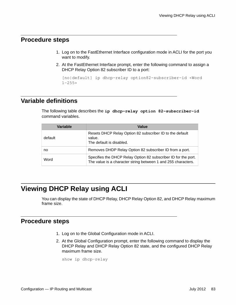
Procedure steps
1. Log on to the FastEthernet Interface configuration mode in ACLI for the port youwant to modify.
2. At the FastEthernet Interface prompt, enter the following command to assign aDHCP Relay Option 82 subscriber ID to a port:
[no|default] ip dhcp-relay option82-subscriber-id <Word1-255>
Variable definitionsThe following table describes the ip dhcp-relay option 82-subscriber-idcommand variables.
Variable Value
defaultResets DHCP Relay Option 82 subscriber ID to the defaultvalue.The default is disabled.
no Removes DHDP Relay Option 82 subscriber ID from a port.
Word Specifies the DHCP Relay Option 82 subscriber ID for the port.The value is a character string between 1 and 255 characters.
Viewing DHCP Relay using ACLIYou can display the state of DHCP Relay, DHCP Relay Option 82, and DHCP Relay maximumframe size.
Procedure steps
1. Log on to the Global Configuration mode in ACLI.
2. At the Global Configuration prompt, enter the following command to display theDHCP Relay and DHCP Relay Option 82 state, and the configured DHCP Relaymaximum frame size.
show ip dhcp-relay
Viewing DHCP Relay using ACLI
Configuration — IP Routing and Multicast July 2012 83

Example:
2526T(config)#show ip dhcp-relayDHCP relay is enabledDHCP relay option82 is disabledDHCP relay max-frame is 576
DHCP relay configuration using ACLI
84 Configuration — IP Routing and Multicast July 2012Comments? [email protected]

Chapter 8: DHCP Server Configurationusing ACLI
If you have no separate DHCP Server or other device available to provide the service to local hosts, youcan use the procedures in this chapter to configure the DHCP Server feature to provide and manage IPv4addresses in your network and eliminate manual TCP/IP configuration.
Displaying the DHCP Server status using ACLIUse this procedure to display the DHCP server status.
Procedure steps
1. Log on to the Privileged Executive ACLI mode.2. At the prompt, enter the following command:
show ip dhcp-serverJob aidThe following shows example output for the show ip dhcp-server command:
2550T-PWR#show ip dhcp-serverDHCP Server: EnabledLease time: 1 day 12 hours 30 minutesDNS servers: 10.10.10.3 10.10.10.4Routers: 11.11.11.5 11.11.11.6
Note:The Router and DNS IP addresses are global, or common, addresses and Pools that do nothave Router and DNS addresses configured within them use these global addresses.
Displaying DHCP Server IP address pools using ACLIUse this procedure to display all DHCP Server IP address pools, or a specific pool.
Configuration — IP Routing and Multicast July 2012 85

Procedure steps
1. Log on to the Privileged Executive ACLI mode.2. At the prompt, enter the following command:
show ip dhcp-server pool [poolName:WORD]Variable definitions
Variable Valuepool Displays all IP address pools
poolName Displays a specific IP address pool. IP address poolnames can be up to 32 alphanumeric characters long. Youcan define up to 32 separate pools.
Displaying DHCP Server IP address leases using ACLIUse this procedure to display IP address lease duration
Procedure steps
1. Log on to the Privileged Executive ACLI mode.2. At the prompt, enter the following command:
show ip dhcp-server leases
Enabling DHCP Server using ACLIUse this procedure to enable DHCP Server on your switch or stack
PrequisitesRequired for a single VLAN configuration:
• Define at least one IP address pool with a network mask• Enable DHCP on TCP/IP interface• Configure valid IPv4 address configuration on the DHCP server so it can offer an address
to the client. NOTE: Because DHCP Server on the switch is, by default, bound to theswitch Management VLAN,the DHCP service uses the switch or stack IP.
DHCP Server Configuration using ACLI
86 Configuration — IP Routing and Multicast July 2012Comments? [email protected]

Required when adding a second or subsequent VLAN to which you want to assign DHCPServer pools:
• Enable IP routing/forwarding on the switch or stack
Procedure stepsNote: If you enable DHCP Snooping, you cannot use DHCP Server. They cannot operatesimultaneously.
1. Log on to the Global Configuration ACLI mode.
2. At the prompt, enter the following command:
ip dhcp-server enable
Disabling the DHCP Server using ACLIUse this procedure to disable DHCP Server or return it to the default setting (disabled).
Procedure steps
1. Log on to the Global Configuration ACLI mode.2. At the prompt, enter the following command:
[no | default] ip dhcp-serverVariable definitions
Variable Valueno Disables DHCP Server
default Returns the list to DHCP Server IP address pool to defaultfor all parameters.
<H.H.H.> Specifies the static MAC allocation for the host IPaddress.
Configuring DHCP Server IP address lease duration usingACLI
Use this procedure to set DHCP Server IP address lease duration. You assign specified IPaddress lease duration to clients, based on the number and type of hosts in your network, tolimit network congestion caused by too-frequent IP address requests.
Disabling the DHCP Server using ACLI
Configuration — IP Routing and Multicast July 2012 87

Procedure steps
1. Log on to the Global Configuration ACLI mode.2. At the prompt, enter the following command:
ip dhcp-server lease {{[days <1-49710>] [hours <0-23>][minutes <0-59>]} | infinite }
Variable definitions
Variable Valuedays Enter a value from 1 to 49710. Default: 1 day 0 hours 0
minutes
hours Enter a value from 0 to 23.
minutes Enter a value from 0 to 59.
infinite Specifies that the lease does not expire.
Job aidThe following example demonstrates how you can set the DHCP Server lease duration to fivedays eight hours.
ip dhcp-server lease 5 days 8 hours
Resetting DHCP Server lease duration to default usingACLI
Use this procedure to set DHCP Server IP address lease duration to the default value of 1 day0 hours 0 minutes.
Procedure steps
1. Log on to the Global Configuration ACLI mode.2. At the prompt, enter the following command:
default ip dhcp-server lease
Configuring DHCP Server routers using ACLIUse this procedure to configure the IP address of a host default gateway for DHCP Server.You can specify up to 8 routers for DHCP Server.
DHCP Server Configuration using ACLI
88 Configuration — IP Routing and Multicast July 2012Comments? [email protected]

Procedure steps
1. Log on to the Global Configuration ACLI mode.2. At the prompt, enter the following command:
ip dhcp-server option-3 routers <ipv4AddrList>Variable definitions
Variable Valueipv4AddrList Enter the IPv4 address of a host default gateway.
If entering multiple routers, separate the entries with aspace.
Job aidThe following example demonstrates how you can configure the IP addresses of two routersfor DHCP Server.
ip dhcp-server option-3 routers 11.11.11.5 11.11.11.6
Clearing DHCP Server router list using ACLIUse this procedure to clear routers from DHCP Server router list.
Procedure steps
1. Log on to the Global Configuration ACLI mode.2. At the prompt, enter the following command:
[no | default] ip dhcp-server option-3 routersVariable definitions
Variable Valueno Clears the DHCP Server router list.
default Returns the list to the default condition, which is empty.
Deleting DHCP Server routers using ACLIUse this procedure to delete DHCP Server routers.
Clearing DHCP Server router list using ACLI
Configuration — IP Routing and Multicast July 2012 89

Procedure steps
1. Log on to the Global Configuration ACLI mode.2. At the prompt, enter the following command:
no ip dhcp-server option-3 routers <ipv4AddrList>Variable definitions
Variable Valueipv4AddrList Enter the DHCP server router IP address, or list of addresses,
that you want to delete.If deleting multiple routers, separate the entries with aspace.
Job aidThe following example demonstrates how you can delete the IP addresses of two routers forDHCP Server.
no ip dhcp-server option-3 routers 11.11.11.5 11.11.11.6
Configuring the Domain Name System server using ACLIUse this procedure to configure up to eight DNS servers.
Procedure steps
1. Log on to the Global Configuration ACLI mode.2. At the prompt, enter the following command:
ip dhcp-server option-6 dns-servers <ipv4AddrList>Variable definitions
Variable Valueipv4AddrList Enter the DNS server IP address or address list.
If entering multiple server, separate the entries with aspace.
Job aidThe following example demonstrates how you can configure the IP addresses of two DNSservers for DHCP Server.
ip dhcp-server option-6 dns-servers 10.10.10.3 10.10.10.4
DHCP Server Configuration using ACLI
90 Configuration — IP Routing and Multicast July 2012Comments? [email protected]

Clearing the Domain Name System server list using ACLIUse this procedure to clear the entries in the DNS server list.
Procedure steps
1. Log on to the Global Configuration ACLI mode.2. At the prompt, enter the following command:
[no | default] ip dhcp-server option-6 dns-serversVariable definitions
Variable Valueno Clears the DNS server list.
default Returns the list to the default condition, which is empty.
Deleting Domain Name System servers using ACLIUse this procedure to delete a DNS server from the DNS server list.
Procedure steps
1. Log on to the Global Configuration ACLI mode.2. At the prompt, enter the following command:
no ip dhcp-server option-6 dns-servers <ipv4AddrList>Variable definitions
Variable Valueipv4AddrList Enter the DNS server IP address, or address list, that you
want to delete.If deleting multiple servers, separate the entries with aspace.
Clearing the Domain Name System server list using ACLI
Configuration — IP Routing and Multicast July 2012 91

Creating a DHCP Server IP address pool using ACLIUse this procedure to create a DHCP Server IP address pool.
Procedure steps
1. Log on to the Global Configuration ACLI mode.2. At the prompt, enter the following command:
ip dhcp-server pool <poolName:WORD/1-32> range <ipv4AddrList>Variable definitions
Variable Valueipv4AddrList Enter the first and last IPv4 address for the pool range.
Job aidThe following provides an example of naming a DHCP Server IP address pool. Use thefollowing command to create a DHCP Server IP address pool named “marketing”.
ip dhcp-server pool marketing range 10.100.3.10 10.100.3.30
Configuring DHCP Server IP address pool options usingACLI
Use this procedure to configure optional settings for DHCP Server IP address pools.
You must create or add pool options on a per pool basis. This is not a global function.
Note:The DHCP Server IP address pool Option 176, Avaya IP Phones, feature supports onlyAvaya 4600 series IP phones for provisioning a number of parameters. When you create aDHCP Server IP Address Pool, Option 176 is automatically enabled with several defaultparameters, with the exception of the MCIPADD and TFTP Server IP address information.
Procedure steps
1. Log on to the Global Configuration ACLI mode.2. At the prompt, enter the following command (include only the options that you need):
ip dhcp-server pool <poolName:WORD/1-32> [host <A.B.C.D><xx:xx:xx:xx:xx:xx> | range <A.B.C.D> <A.B.C.D> | option-60vendor-class-identifier <WORD> [lease { {[days <1-49710>]
DHCP Server Configuration using ACLI
92 Configuration — IP Routing and Multicast July 2012Comments? [email protected]
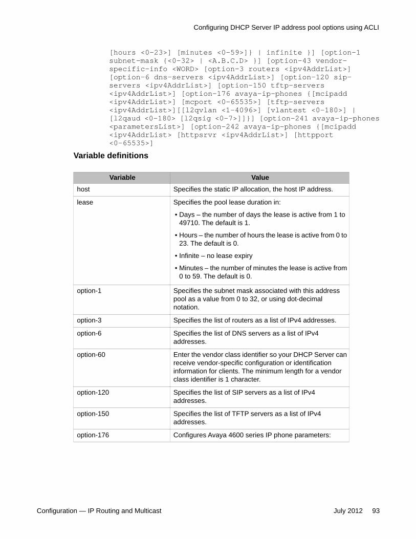
[hours <0-23>] [minutes <0-59>]} | infinite }] [option-1subnet-mask {<0-32> | <A.B.C.D> }] [option-43 vendor-specific-info <WORD> [option-3 routers <ipv4AddrList>][option-6 dns-servers <ipv4AddrList>] [option-120 sip-servers <ipv4AddrList>] [option-150 tftp-servers<ipv4AddrList>] [option-176 avaya-ip-phones {[mcipadd<ipv4AddrList>] [mcport <0-65535>] [tftp-servers<ipv4AddrList>][[l2qvlan <1-4096>] [vlantest <0-180>] |[l2qaud <0-180> [l2qsig <0-7>]]}] [option-241 avaya-ip-phones<parametersList>] [option-242 avaya-ip-phones {[mcipadd<ipv4AddrList> [httpsrvr <ipv4AddrList>] [httpport<0-65535>]
Variable definitions
Variable Valuehost Specifies the static IP allocation, the host IP address.
lease Specifies the pool lease duration in:
• Days – the number of days the lease is active from 1 to49710. The default is 1.
• Hours – the number of hours the lease is active from 0 to23. The default is 0.
• Infinite – no lease expiry
• Minutes – the number of minutes the lease is active from0 to 59. The default is 0.
option-1 Specifies the subnet mask associated with this addresspool as a value from 0 to 32, or using dot-decimalnotation.
option-3 Specifies the list of routers as a list of IPv4 addresses.
option-6 Specifies the list of DNS servers as a list of IPv4addresses.
option-60 Enter the vendor class identifier so your DHCP Server canreceive vendor-specific configuration or identificationinformation for clients. The minimum length for a vendorclass identifier is 1 character.
option-120 Specifies the list of SIP servers as a list of IPv4addresses.
option-150 Specifies the list of TFTP servers as a list of IPv4addresses.
option-176 Configures Avaya 4600 series IP phone parameters:
Configuring DHCP Server IP address pool options using ACLI
Configuration — IP Routing and Multicast July 2012 93

Variable Value
• Mcipadd – enter an IP Phone IPv4 address or list ofaddresses
• Mcport—enter a value from -1 to 65535 to specify theUDP port the IP Phone uses for registration. The defaultis 1719. A value of -1 indicates that the UDP port is notincluded in the configuration
• TFTP servers—enter one IPv4 address, or multiple IPv4addresses, of TFTP servers where IP Phones can collectconfiguration information
• L2qvlan—enter a value from -1 to 4096 to specify the802.1Q VLAN ID. The default is 0. A value of -1 indicatesthat this parameter is not included in the configuration
• Vlantest—enter a value from -1 to 999 to specify thenumber of seconds a phone will attempt to return to thepreviously known voice VLAN. A value of -1 indicates thatthis parameter is not included in the configuration
• L2qaud—enter a value from -1 to 7 to specify the layer 2audio priority value. A value of -1 indicates that thisparameter is not included in the configuration.
• L2qsig—enter a value from -1 to 7 to specify the layer 2signaling priority value. A value of -1 indicates that thisparameter is not included in the configuration.
option-241 Configures parameters for Avaya 1100, 1200 and 2000series IP Phones. For the list of supported parameters, seeDHCP Server Option 241 parameters on page 98. If theparameter is not included, the parameter will retain itsdefault value, or the value that was previously provisionedfor the specific parameter. Parameter value is between theequals sign and semicolon. Format and example of theparameter list: Nortel-i2004–B,s1ip=47.11.62.20;p1=4100;a1=1;r1=255;s2ip=47.11.62.21;p2=4100;a2=1;r2=2;Note that the use of Nortel-i2004–B specific option at thebeginning of the string is optional.
option-242 Configures parameters for Avaya 1600 and 9600 series IPPhones. The following parameters are supported:
• httpport – enter a value from 0 to 65535 to specify theHTTP port. The default is 80.
• httpsrvr – enter an IP Phone IPv4 address or list ofaddresses. You can enter up to eight (8) IP addresses.
• mcipadd – enter an IP Phone IPv4 address or list ofaddresses. You can enter up to eight (8) Call Server IPAddresses. This parameter is used as a backup for the
DHCP Server Configuration using ACLI
94 Configuration — IP Routing and Multicast July 2012Comments? [email protected]

Variable Value
IP phone in case the HTTP Server is unavailable, inwhich case the IP phone can reach the Call Server.
range Specifies the IP address allocation list.
ExamplesWhen you configure a router and/or DNS entry for a Pool, that entry overrides the Global DNSand/or Router settings.
Following are some examples that demonstrate setting the router and DNS parameters insidea pool.
(config#)ip dhcp-server pool marketing option-6 dns-servers10.10.200.90config)# ip dhcp-server pool sales option-6 routers 10.10.20.1(config)# ip dhcp-server pool marketing option-150 tftp-servers10.10.200.95
DHCP Server Option 43 vendor specific informationThe following table lists the code types supported with the DHCP Server Option-43 vendorspecific info command.
Name Code Type Descriptionsnmk 1 ip Subnet mask of the IP address to be allocated.
Default: natural mask corresponding to the IPaddress.The server does not issue IP addresses toclients on different subnets.
tmof 2 long Time offset from UTC, in seconds.
rout 3 iplist List of routers on the same subnet as theclient.
tmsv 4 iplist A list of time servers (RFC 868).
nmsv 5 iplist A list of name servers (IEN 116).
dnsv 6 iplist A list of DNS servers (RFC 1035).
lgsv 7 iplist A list of MIT-LCS UDP log servers.
chsv 8 iplist A list of Cookie servers (RFC 865).
lpsv 9 iplist A list of LPR servers (RFC 1179).
DHCP Server Option 43 vendor specific information
Configuration — IP Routing and Multicast July 2012 95

Name Code Type Descriptionimsv 10 iplist A list of Imagen Impress servers.
rlsv 11 iplist A list of Resource Location servers (RFC 887).
hstn 12 str Host name of the client.
btsz 13 short Size of the boot image.
mdmp 14 str Path name to which client dumps core.
dnsd 15 str Domain name for DNS.
swsv 16 ip IP address of swap server.
rpth 17 str Path name of root disk of the client.
epth 18 str Extensions Path (RFC 1533).
plcy 21 ippairs Policy filter for non-local source routing. A list ofpairs of: Destination IP, Subnet mask.
mdgs 22 short Maximum size of IP datagram that the clientshould be able to reassemble.
ditl 23 octet Default IP TTL.
mtat 24 long Aging timeout, in seconds, to be used with PathMTU discovery (RFC 1191).
mtpt 25 mtpt A table of MTU sizes to be used with Path MTUDiscovery.
ifmt 26 short MTU to be used on an interface.
brda 28 ip Broadcast address in use on the client subnet.The system calculates the default from thesubnet mask and the IP address.
rtsl 32 ip Destination IP address to which the client sendsrouter solicitation request.
strt 33 ippairs A table of static routes for the client consistingof pairs (Destination, Router). You cannotspecify the default route as a destination.
arpt 35 long Timeout, in seconds, for ARP cache.
dttl 37 octet Default TTL of TCP.
kain 38 long Client TCP keepalive interval, in seconds.
nisd 40 str Domain name for NIS.
nisv 41 iplist A list of NIS servers
ntsv 42 iplist A list of NTP servers.
vend 43 str Vendor Specific Options—must be specified inthe following format:
DHCP Server Configuration using ACLI
96 Configuration — IP Routing and Multicast July 2012Comments? [email protected]
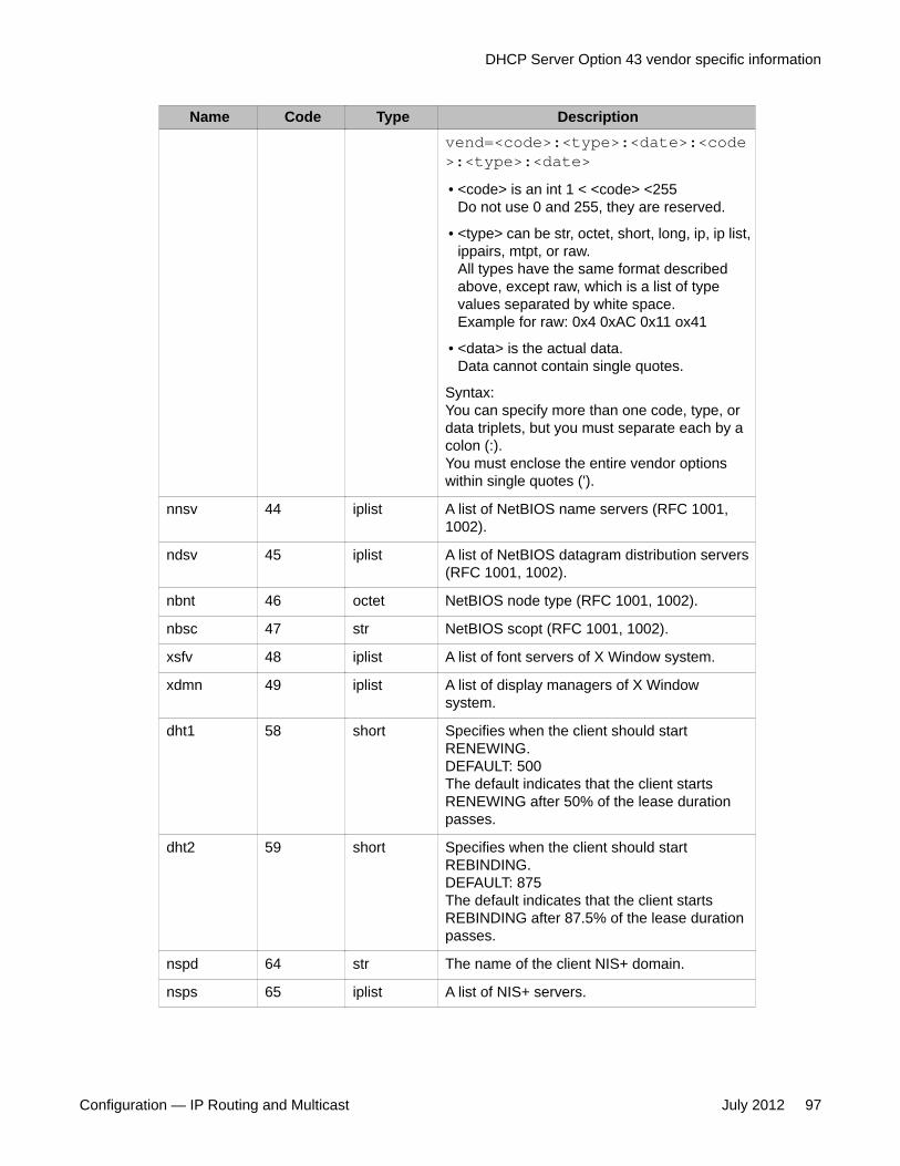
Name Code Type Descriptionvend=<code>:<type>:<date>:<code>:<type>:<date>• <code> is an int 1 < <code> <255
Do not use 0 and 255, they are reserved.
• <type> can be str, octet, short, long, ip, ip list,ippairs, mtpt, or raw.All types have the same format describedabove, except raw, which is a list of typevalues separated by white space.Example for raw: 0x4 0xAC 0x11 ox41
• <data> is the actual data.Data cannot contain single quotes.
Syntax:You can specify more than one code, type, ordata triplets, but you must separate each by acolon (:).You must enclose the entire vendor optionswithin single quotes (').
nnsv 44 iplist A list of NetBIOS name servers (RFC 1001,1002).
ndsv 45 iplist A list of NetBIOS datagram distribution servers(RFC 1001, 1002).
nbnt 46 octet NetBIOS node type (RFC 1001, 1002).
nbsc 47 str NetBIOS scopt (RFC 1001, 1002).
xsfv 48 iplist A list of font servers of X Window system.
xdmn 49 iplist A list of display managers of X Windowsystem.
dht1 58 short Specifies when the client should startRENEWING.DEFAULT: 500The default indicates that the client startsRENEWING after 50% of the lease durationpasses.
dht2 59 short Specifies when the client should startREBINDING.DEFAULT: 875The default indicates that the client startsREBINDING after 87.5% of the lease durationpasses.
nspd 64 str The name of the client NIS+ domain.
nsps 65 iplist A list of NIS+ servers.
DHCP Server Option 43 vendor specific information
Configuration — IP Routing and Multicast July 2012 97

Name Code Type Descriptionmiph 68 iplist A list of mobile IP home agents.
smtp 69 iplist A list of SMTP servesrs
pops 70 iplist A list of POP3 servers.
nntp 71 iplist A list of NNTP servers.
wwws 72 iplist A list of WWW servers.
fngs 73 iplist A list of Finger servers.
ircs 74 iplist A list of IRC servers.
stsv 75 iplist A list of StreetTalk servers.
stda 76 iplist A list of STDA servers.
Note:For any code number not in this list you must use a default of str (string). For example:200:str:information. Option numbers 0 and 255 are reserved.
DHCP Server Option 241 parametersThe following table lists the parameters supported with the DHCP Server Option 241command.
Parameter Value Descriptions1ip Value from 0.0.0.0 to
255.255.255.255Primary server IP address
p1 Value from 1 to 65535 Primary server port number
a1 Value from 0 to 255 Primary server action code
r1 Value from 0 to 255 Primary server retry count
s2ip Value from 0.0.0.0 to255.255.255.255
Secondary server IP address
p2 Value from 1 to 65535 Secondary server port number
a2 Value from 0 to 255 Secondary server action code
r2 Value from 0 to 255 Secondary server retry count
dhcp ‘y’ yes‘n’ no
Enable DHCP
DHCP Server Configuration using ACLI
98 Configuration — IP Routing and Multicast July 2012Comments? [email protected]

Parameter Value Descriptionxip Value from 0.0.0.0 to
255.255.255.255XAS server IP address
xp Value from 0 to 65535 XAS server port number
xa Character string made up of thefollowing character‘g’ graphical XAS mode‘f’ full screen XAS mode‘s’ secure XAS mode‘h’ hidden Phone mode‘r’ reduced Phone mode
XAS server action code (XAS Mode andPhone Mode)Note that there is no explicit character toselect text-mode. Instead, the lack ofspecifying graphical ‘g’ implies the XASmode is text.Also note that there is no explicitcharacter to select Full phone mode.Instead, the lack of specifying eitherhidden ‘h’ or reduced ‘r” implies thephone is to be provisioned for Fullphone mode. Please be careful not toconfuse Full Screen XAS mode ‘f’ withFull phone mode.Note that hidden Phone mode andreduced Phone mode are supported onthe IP Phone 2007 only.
unid Character string up to 32characters
Unique network identification
menulock ‘f’ full lock‘p’ partial lock‘u’ unlock
Menu lock mode
vq ‘y’ yes‘n’ no
Enable 802.1Q for voice [1]
vcp Value from 0 to 8 802.1Q control p bit for voice stream.Provisioning this value to 8 tells thephone to use the value it receives fromthe LLDP Network Policy TLV or fromthe call server
vmp Value from 0 to 8 802.1Q media p bit for voice stream.Provisioning this value to 8 tells thephone to use the value it receives fromthe LLDP Network Policy TLV or fromthe call server
vlanf ‘y’ yes‘n’ no
Enable VLAN filter on voice stream
nis ‘a’ auto negotiation‘10’ 10 Mbps‘100’ 100 Mbps
Network port speed [1]
nid ‘a’ auto negotiation‘f’ full duplex
Network port duplex [1]
DHCP Server Option 241 parameters
Configuration — IP Routing and Multicast July 2012 99
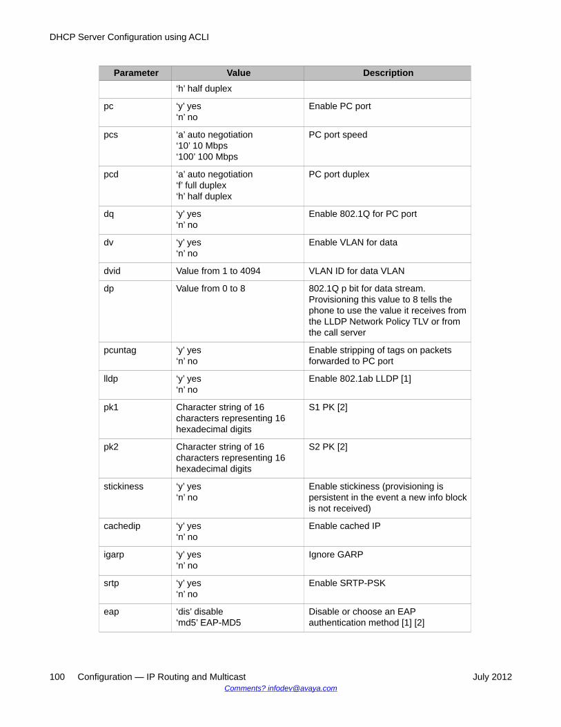
Parameter Value Description‘h’ half duplex
pc ‘y’ yes‘n’ no
Enable PC port
pcs ‘a’ auto negotiation‘10’ 10 Mbps‘100’ 100 Mbps
PC port speed
pcd ‘a’ auto negotiation‘f’ full duplex‘h’ half duplex
PC port duplex
dq ‘y’ yes‘n’ no
Enable 802.1Q for PC port
dv ‘y’ yes‘n’ no
Enable VLAN for data
dvid Value from 1 to 4094 VLAN ID for data VLAN
dp Value from 0 to 8 802.1Q p bit for data stream.Provisioning this value to 8 tells thephone to use the value it receives fromthe LLDP Network Policy TLV or fromthe call server
pcuntag ‘y’ yes‘n’ no
Enable stripping of tags on packetsforwarded to PC port
lldp ‘y’ yes‘n’ no
Enable 802.1ab LLDP [1]
pk1 Character string of 16characters representing 16hexadecimal digits
S1 PK [2]
pk2 Character string of 16characters representing 16hexadecimal digits
S2 PK [2]
stickiness ‘y’ yes‘n’ no
Enable stickiness (provisioning ispersistent in the event a new info blockis not received)
cachedip ‘y’ yes‘n’ no
Enable cached IP
igarp ‘y’ yes‘n’ no
Ignore GARP
srtp ‘y’ yes‘n’ no
Enable SRTP-PSK
eap ‘dis’ disable‘md5’ EAP-MD5
Disable or choose an EAPauthentication method [1] [2]
DHCP Server Configuration using ACLI
100 Configuration — IP Routing and Multicast July 2012Comments? [email protected]

Parameter Value Description‘peap’ PEAP/MD5‘tls’ EAP-TLS
eapid1 Character string up to 32characters
802.1x (EAP) device ID1 [1] [2]
eapid2 Character string up to 32characters
802.1x (EAP) device ID2 [1] [2]
eappwd Character string up to 32characters
802.1x (EAP) password [1] [2]
ca Character string up to 80characters
Certificate Authority (CA) server
cahost Character string up to 32characters
Certificate Authority (CA) host name
cadomain Character string up to 50characters
Certificate Authority (CA) domain name
cdiff Value from 0 to 255 Diffserv code points for controlmessages
mdiff Value from 0 to 255 Diffserv code points for mediamessages
prov Character string up to 50characters
Provisioning server address or URL (ifthe string is prefixed with “http://” thephone will connect to a HTTP server,otherwise the phone will connect to aTFTP server)
dns Character string up to 50characters
Primary DNS server URL
dns2 Character string up to 50characters
Secondary DNS server URL
ct Value from 0 to 15 for IP Phone1100 seriesValue from 7 to 39 for IP Phone2007
Contrast value
br Value from 0 to 15 Brightness value
blt ‘0’ 5 seconds‘1’ 1 minute‘2’ 5 minutes‘3’ 10 minutes‘4’ 15 minutes‘5’ 30 minutes‘6’ 1 hour‘7’ 2 hours‘8’ always on
Backlight timer
DHCP Server Option 241 parameters
Configuration — IP Routing and Multicast July 2012 101

Parameter Value Descriptiondim ‘y’ yes
‘n’ noAs of UNIStim software release 3.4, thepreviously supported “dim” parameter isno longer supported since itsfunctionality is superseded by the dimtparameter. The phone will still acceptthe dim parameter to prevent errorswhen reading existing provisioning filesbut the parameter will be ignored infavor of the new dimt parameter.
dimt ‘0’ Off‘1’ 5 seconds‘2’ 1 minute‘3’ 5 minutes‘4’ 15 minutes‘5’ 30 minutes‘6’ 1 hour‘7’ 2 hours
Phone inactivity timer to dim the screen(IP Phone 2007 only)
bt ‘y’ yes‘n’ no
Enable Bluetooth (IP Phone 1140E and1150E only)
zone Character string up to 8characters
Zone ID
file Character string up of thefollowing character‘z’ read zone file‘t’ read type file'd' read device file
For system specific provisioning filespecifies what other provisioning files toread
hd Character string up of thefollowing character‘w’ wired‘b’ Bluetooth‘n’ none
Headset type
ar ‘y’ yes‘n’ no
Enable Auto-recovery
arl ‘cr’ critical‘ma’ major‘mi’ minor
Auto-recovery level
ll ‘cr’ critical‘ma’ major‘mi’ minor
Log level
ssh ‘y’ yes‘n’ no
Enable SSH
sshid Character string between 4 and12 characters
SSH user ID [2]
DHCP Server Configuration using ACLI
102 Configuration — IP Routing and Multicast July 2012Comments? [email protected]

Parameter Value Descriptionsshpwd Character string between 4 and
12 charactersSSH password [2]
bold ‘y’ yes‘n’ no
Enable bold on font display
menupwd String between and 21characters containing onlynumeric digits, asterisk (*) andhash (#) – i.e. only the dialpadsymbols
Administrator password [2]
vvsource ‘n’ no VLAN‘a’ auto VLAN via DHCP‘lv’ auto VLAN via VLAN NameTLV‘lm’ auto VLAN via NetworkPolicy TLV
Source of VLAN information
srtpid 96115120
Payload type ID
ntqos ‘y’ yes‘n’ no
Enable Nortel Automatic QoS
dscpovr ‘y’ yes‘n’ no
DSCP Precedence Override
vpn ‘y’ yes‘n’ no
Enable the UNIStim VPN Client (UVC)within the phone
vpntype ‘1’ Nortel VPN Only Nortel VPN devices are supportedat this time
vpnmode ‘aggressive’‘main’
Authentication mode
vpnauth ‘psk’ preshared key‘certificate’ X.509 certificate
Authentication credentialWhen ‘certificate’ is provisioned, both aCA root certificate and a devicecertificates must be installed in thephone.
vpnxauth ‘0’ none‘1’ password
X Authentication type
vpnpskuser Character string up to 64characters
PreShared Key (PSK) User ID
vpnpskpwd Character string up to 64characters
PreShared Key (PSK) password
vpnxauthuser Character string up to 64characters
X Authentication User ID
DHCP Server Option 241 parameters
Configuration — IP Routing and Multicast July 2012 103

Parameter Value Descriptionvpnxauthpwd Character string up to 64
charactersX Authentication password
vpns1 Character string up to 64characters
IP address or FQDN of the primary VPNserverIf a FQDN is entered, the remote user’slocal network must have access to DNSto resolve the entered name. Typicallyin a home environment, this would bethe service provider’s DNS.
vpns2 Character string up to 64characters
IP address or FQDN of the secondaryVPN server
vpndiffcpy ‘y’ copy DSCP from innerpacket‘n’ use vpndiff value
Source of DSCP value for the tunneltraffic. Determines if DSCP value iscopied from inner packet to outer packetor if vpndiff is used.
vpndiff 0–255 If vpndiffcpy=n, then this value is usedfor the DSCP value for the tunnel traffic
vpnmotd 0-999 Message of the Day (MOTD) timer
dcpsource1 ‘scep’‘pkcs12’
Method used to install devicecertificates
dcpactive1 ‘n’ Inactive‘y’ Active
Profile is active or not
dcppurpose1 Character string made up of thefollowing character‘a’ All applications‘v’ VPN‘d’ DTLS‘s’ SCR‘g’ GXAS‘e’ EAP-TLS‘l’ Licensing
Specifies which phone applications canuse this device certificateMultiple values can be cascaded (e.g.‘dsg’) but ‘a’ can only be used by itself
dcprenew1 Integer value, but also supportsthe following special values‘-1’ Never‘0’ Immediately
Number of days prior to certificateexpiry that a certificate renewal isrequested
dcpdelete1 ‘n’ No action‘y’ Delete
If set to ‘y’ forces the device certificateto be deleted
dcpautocn1 ‘0’ Manual‘1’ Automatic
Automatically construct the CertificateName using cadomain and cahost
dcpcaname1 Character string of 128characters
CA name included in the SCEP requestto identify requested CA (note that notall CA require the CA name)
DHCP Server Configuration using ACLI
104 Configuration — IP Routing and Multicast July 2012Comments? [email protected]

Parameter Value Descriptiondcphostnameoverride1
Character string of 128characters
Override hostname (cahost) for thisDCP only
dcpattrcn1 Character string of 128characters
If “Auto CN” is disabled, this value isused instead of combining cadomainand cahost
dcpattrextkeyusage1
Character string made up ofone of the following characters‘a’ anyExtendedKeyUsage‘c’ clientAuth‘i’ ipsecIKE (RFC 4945)‘m’ iKEIntermediate’ ’ no Extended Key Usage
Define the Extended Key Usageattributes to be requested for the devicecertificate.The default is clientAuth.
Note:[1]: Warning - changing this parameter could impact the network connectivity and mayrequire manual correction[2]: Warning – provisioning this parameter via TFTP, HTTP, or DHCP means that secureinformation is transferred in clear text
Deleting Option 241 parameters for DHCP server pool Use this procedure to remove parameters or reset parameters to default values for DHCPServer Option 241 for Avaya 1100, 1200 and 2000 IP Phones.
Procedure steps
1. Log on to the Global Configuration ACLI mode.2. To set parameters to default, enter:
[no | default] ip dhcp-server pool <poolName:WORD/1-32>option-241 avaya-ip-phones
3. To remove individual parameters from the provisioning string for Option 241, enter:
no ip dhcp-server pool <poolName:WORD/1-32> option-241 avaya-ip-phones <parameterList>
Variable definitions
Variable Value<parameterList> Specifies the individual parameters to be
removed.The format for <parameterList> is: Nortel-i2004–B,param1, param2, param3,...
Deleting Option 241 parameters for DHCP server pool
Configuration — IP Routing and Multicast July 2012 105

Variable ValueNote: The use of Nortel-i2004–B specificoption at the beginning of the string isoptional.See DHCP Server Option 241 parameters onpage 98 for the list of supportedparameters.
Deleting Option 242 parameters for DHCP server poolUse this procedure to remove parameters or reset parameters to default values for DHCPServer Option 242 for Avaya 1600 and 9600 Series IP Phones.
The embedded DHCP Server for this option supports the configuration and provisioning ofselected (not all) parameters.
Procedure steps
1. Log on to the Global Configuration ACLI mode.2. To set parameters to default, enter:
[no | default] ip dhcp-server pool <poolName:WORD/1-32>option-242 avaya-ip-phones [httpport][httpsrvr][mcipadd]
3. To remove individual MCIPADD and HTTP servers from lists for Option 242, enter:
no ip dhcp-server pool <poolName:WORD/1-32> option-242 avaya-ip-phones [httpsrvr <ipv4AddrList>][mcipadd <ipv4AddrList>]
Variable definitions
Variable Value<ipv4AddrList> Specifies an IP Phone IPv4 address or list of
addresses to be removed.
Disabling DHCP Server IP address pools using ACLIUse this procedure to disable DHCP Server IP address pools.
Procedure steps
1. Log on to the Global Configuration ACLI mode.2. At the prompt, enter the following command:
DHCP Server Configuration using ACLI
106 Configuration — IP Routing and Multicast July 2012Comments? [email protected]

[no | default] ip dhcp-server pool <poolName:WORD/1-32>Variable definitions
Variable Valueno Clears the specified DHCP Server IP address pool.
default Returns the list to DHCP Server IP address pool to default,which is disabled.
Configuring static IP addresses using ACLIUse this procedure to configure the entry of reserved IP addresses for static devices (such asprinters).
Procedure steps
1. Log on to the Global Configuration ACLI mode.2. At the prompt, enter the following command:
ip dhcp-server pool <poolName:WORD/1-32> host <A.B.C.D><xx:xx:xx:xx:xx:xx>
Variable definitions
Variable Valuepool Displays all IP address pools.
poolName Displays a specific IP address pool. IP address pool namescan be up to 32 alphanumeric characters long. You can defineup to 32 separate pools.
host Specifies the static IP allocation, the host IP address.
Job aidThe following is an example of configuring a static IP address for “Printer2ndFloor”.
(config)# ip dhcp-server pool Printer2ndFloor host 10.100.3.5001:12:23:34:45:56
Configuring static IP addresses using ACLI
Configuration — IP Routing and Multicast July 2012 107

Creating the IP DHCP Server Pool for a Vendor ClassIdentifier
Use this procedure to create the IP DHCP Server Pool for a Vendor Class Identifier.
Procedure steps
1. Log on to the Global Configuration ACLI mode.2. At the prompt, enter the following command:
ip dhcp-server pool <poolName:WORD/1-32> option-60 vendor-class-identifier <WORD> option-43 vendor-specific-info<WORD>
Variable definitions
Variable Value<WORD> <option number>:<type (IP/ASCII string/hex)>:<value>
DHCP Server Configuration using ACLI
108 Configuration — IP Routing and Multicast July 2012Comments? [email protected]

Chapter 9: UDP broadcast forwardingconfiguration using ACLI
This chapter describes the procedures you can use to configure UDP broadcast forwarding using ACLI.UDP broadcast forwarding is a general mechanism for selectively forwarding limited UDP broadcastsreceived on an IP interface to a configured IP address.
You cannot enable or disable the UDP broadcast forwarding feature on a global level. When you attachthe first UDP forwarding list to a VLAN interface, the feature is enabled. When you remove the last UDPforwarding list from a VLAN, the feature is disabled.
Prerequisites to UDP broadcast forwarding using ACLI• Enable IP routing globally.
• Enable IP routing and configure an IP address on the VLAN to be configured as a UDPforwarding interface.
• Ensure that a route (local or static) to the destination address is available on the switch.
Important:If you configure EAPOL on the switch, enable EAPOL before enabling UDP Forwarding,otherwise the UDP broadcast traffic matching UDP forward lists is forwarded regardless ofthe EAPOL port state (authorized, force unauthorized, or auto).
UDP broadcast forwarding configuration proceduresTo configure UDP broadcast forwarding, perform the following steps:
1. Create UDP protocol entries that specify the protocol associated with each UDPport that you want to forward.
2. Create a UDP forwarding list that specifies the destination IP addresses for eachforwarding UDP port. (You can create up to 128 UDP forwarding lists.)
3. Apply UDP forwarding lists to local VLAN interfaces.
Configuration — IP Routing and Multicast July 2012 109

Configuring UDP protocol table entriesUse this procedure to create UDP protocol table entries that identify the protocols associatedwith specific UDP ports that you want to forward.
Procedure steps
To configure a UDP table entry, enter the following from the Global Configuration mode:
ip forward-protocol udp [<forwarding_port> <protocol_name>]
Variable definitionsThe following table describes the ip forward-protocol udp command variables.
Variable Value<forwarding_port>
Specifies the UDP port number. Range is 1-65535.
<protocol_name> Specifies the UDP protocol name.
Displaying the UDP protocol tableUse this procedure to display the configured UDP protocol table entries.
Procedure steps
To display the UDP protocol table, enter the following from the User Exec mode:
UDP broadcast forwarding configuration using ACLI
110 Configuration — IP Routing and Multicast July 2012Comments? [email protected]

show ip forward-protocol udp
Job aidThe following table shows the field descriptions for the show ip forward-protocol udpcommand.
Field DescriptionUDP_PORT Indicates the UDP ports.
PROTOCOL_NAME Indicates the name of the associated protocol.
Configuring a UDP forwarding listUse this procedure to configure a UDP forwarding list, which associates UDP forwarding portswith destination IP addresses. Each forwarding list can contain multiple port/destinationentries. You can configure a maximum of 16 port/destination entries in one forwarding list.
You can configure up to 128 forwarding lists.
Procedure steps
To configure a UDP port forwarding list, enter the following from the GlobalConfiguration mode:
ip forward-protocol udp portfwdlist <forward_list> <udp_port><dest_ip> [name <list_name>]
Variable definitionsThe following table describes the ip forward-protocol udp portfwdlist commandvariables.
Variable Value<forward_list> Specifies the ID of the UDP forwarding list. Range is 1-128.
<udp_port> Specifies the port on which the UDP forwarding originates.
<dest_ip> Specifies the destination IP address for the UDP port.
Configuring a UDP forwarding list
Configuration — IP Routing and Multicast July 2012 111

Variable Value<list_name> Specifies the name of the UDP forwarding list being created
(maximum 15 characters).
Applying a UDP forwarding list to a VLANUse this procedure to associate a UDP forwarding list with a VLAN interface (you can attachonly one list at a time to a VLAN interface).
You can bind the same UDP forwarding list to a maximum of 16 different VLANs.
Procedure steps
To associate a UDP forwarding list to a VLAN, enter the following from the VLANInterface Configuration mode:
ip forward-protocol udp [vlan <vid>] [portfwdlist<forward_list>] [broadcastmask <bcast_mask>] [maxttl <max_ttl>]
Variable definitionsThe following table describes the ip forward-protocol udp command variables.
Variable Value<vid> Specifies the VLAN ID on which to attach the UDP forwarding list.
This parameter is optional, and if not specified, the UDPforwarding list is applied to the interface specified in theinterface vlan command.
<forward_list> Specifies the ID of the UDP forwarding list to attach to theselected VLAN interface.
<bcast_mask> Specifies the 32-bit mask used by the selected VLAN interfaceto make forwarding decisions based on the destination IPaddress of the incoming UDP broadcast traffic. If you do notspecify a broadcast mask value, the switch uses the mask of theinterface to which the forwarding list is attached. (See Note 1.)
<max_ttl> Specifies the time-to-live (TTL) value inserted in the IP headersof the forwarded UDP packets coming out of the selected VLANinterface. If you do not specify a TTL value, the default value (4)is used. (See Note 1.)
UDP broadcast forwarding configuration using ACLI
112 Configuration — IP Routing and Multicast July 2012Comments? [email protected]

Variable ValueNote 1: If you specify maxttl and/or broadcastmask values with no portfwdlist specified, theswitch saves the settings for this interface. If you subsequently attach portfwdlist to thisinterface without defining the maxttl and/or broadcastmask values, the saved parametersare automatically attached to the list. But, if when specifying the portfwdlist, you also specifythe maxttl and/or broadcastmask, your specified properties are used, regardless of anyprevious configurations.
Displaying the UDP broadcast forwarding configurationUse this procedure to display the UDP broadcast forwarding configuration.
Procedure steps
To display the UDP broadcast forwarding configuration, enter the following from theUser Exec mode:
show ip forward-protocol udp [interface [vlan <1-4094>]][portfwdlist [<portlist>]
Variable definitionsThe following table describes the show ip forward-protocol udp command variables.
Variable Value[interface [vlan<1-4094>]]
Displays the configuration and statistics for a VLAN interface. Ifno VLAN is specified, the configuration for all UDP forwarding-enabled VLANs is displayed.
[portfwdlist[<forward_list>]
Displays the specified UDP forwarding list. If no list is specified,a summary of all forwarding lists is displayed.
Job aidsThe following table shows the field descriptions for the show ip forward-protocol udpcommand.
Displaying the UDP broadcast forwarding configuration
Configuration — IP Routing and Multicast July 2012 113

Field DescriptionUDP_PORT Indicates the UDP ports.
PROTOCOL_NAME Indicates the name of the protocol.
The following table shows the field descriptions for the show ip forward-protocol udpinterfaces command.
Field DescriptionINTF_ADDR Indicates the IP address of the interface.
FWD LISTID Identifies the UDP forwarding policy.
MAXTTL Indicates the maximum TTL.
RXPKTS Indicates the number of received packets.
FWDPKTS Indicates the number of forwarded packets.
DRPDEST UNREACH Indicates the number of dropped packets that cannot reach thedestination.
DRP_UNKNOWNPROTOCOL
Indicates the number of packets dropped with an unknownprotocol.
BDCASTMASK Indicates the value of the broadcast mask.
The following table shows the field descriptions for the show ip forward-protocol udpportfwdlist command.
Field DescriptionLIST_ID Specifies the UDP forwarding policy number.
NAME Specifies the name of the UDP forwarding policy.
Clearing UDP broadcast counters on an interfaceUse this procedure to clear the UDP broadcast counters on an interface.
Procedure steps
To clear the UDP broadcast counters, enter the following from the Privileged Execcommand mode:
UDP broadcast forwarding configuration using ACLI
114 Configuration — IP Routing and Multicast July 2012Comments? [email protected]
clear ip forward-protocol udp counters <1-4094>
Variable definitionsThe following table describes the clear ip forward-protocol udp counterscommand variables.
Variable Value<1-4094> Specifies the VLAN ID.
Clearing UDP broadcast counters on an interface
Configuration — IP Routing and Multicast July 2012 115

UDP broadcast forwarding configuration using ACLI
116 Configuration — IP Routing and Multicast July 2012Comments? [email protected]

Chapter 10: Directed broadcastsconfiguration using ACLI
This chapter describes the procedures you can use to configure and display the status of directedbroadcasts using ACLI.
Configuring directed broadcastsUse this procedure to enable directed broadcasts on the switch. By default, directed broadcastsare disabled.
Prerequisites
• Enable IP routing globally.
• Enable IP routing and configure an IP address on the VLAN to be configured as abroadcast interface.
• Ensure that a route (local or static) to the destination address is available on the switch.
Procedure steps
To enable directed broadcasts, enter the following from the Global Configuration mode:
ip directed-broadcast enable
Displaying the directed broadcast configurationUse this procedure to display the status of directed broadcasts on the switch. By default,directed broadcasts are disabled.
Configuration — IP Routing and Multicast July 2012 117

Procedure steps
To display directed broadcast status, enter the following from the User EXEC mode:
show ip directed-broadcast
Directed broadcasts configuration using ACLI
118 Configuration — IP Routing and Multicast July 2012Comments? [email protected]
Chapter 11: Static ARP and Proxy ARPconfiguration using ACLI
This chapter describes the procedures you can use to configure Static ARP, Proxy ARP, and display ARPentries using the ACLI.
Static ARP configurationThis section describes how to configure Static ARP using the ACLI.
Configuring a static ARP entryUse this procedure to configure a static ARP entry.
Prerequisites
• Enable IP routing globally.
• Enable IP routing and configure an IP address on the target VLAN.
Procedure steps
To configure a static ARP entry, enter the following from the Global Configuration mode:
[no] ip arp <A.B.C.D> <aa:bb:cc:dd:ee:ff> <unit / port> [vid<1-4094>]
Variable definitionsThe following table describes the ip arp command variables.
Configuration — IP Routing and Multicast July 2012 119
Variable Value[no] Removes the specified ARP entry.
<A.B.C.D> Specifies the IP address of the device being set as a static ARPentry.
<aa:bb:cc:dd:ee:ff>
Specifies the MAC address of the device being set as a staticARP entry.
<unit / port> Specifies the unit and port number to which the static ARP entryis being added.
vid <1-4094> Specifies the VLAN ID to which the static ARP entry is beingadded.
Displaying the ARP tableUse the following procedures to display the ARP table, configure a global timeout for ARPentries, and clear the ARP cache.
Navigation• Displaying ARP entries on page 120• Configuring a global timeout for ARP entries on page 122• Clearing the ARP cache on page 122
Displaying ARP entriesUse this procedure to display ARP entries.
Procedure steps
To display ARP entries, enter the following from the User Exec mode:
show arp-tableOR
show ip arp [<ip-addr>] [-s <subnet> <mask>] [static <ip-addr>[-s <subnet> <mask>]][<mac-addr>] [dynamic <ip-addr> [-s
Static ARP and Proxy ARP configuration using ACLI
120 Configuration — IP Routing and Multicast July 2012Comments? [email protected]

<subnet> <mask>]][<mac-addr>] [<mac_addr>] [summary] [vlan <1–4096>]The show ip arp command is invalid if the switch is not in Layer 3 mode.
Variable definitionsThe following table describes the show ip arp command variables.
Variable Valuedynamic <ip-addr>[-s <subnet><mask>]
Displays dynamic entries for the specified subnet. If you do notspecify a subnet, all dynamic entries are displayed.
<ip-addr> Specifies the IP address of the ARP entry to be displayed.
<mac-addr> Specifies the MAC address of the ARP entry to be displayed.The format can be H.H.H, xx:xx:xx:xx:xx:xx, xx.xx.xx.xx.xx.xx,or xx-xx-xx-xx-xx-xx-.
-s <subnet><mask>
Displays ARP entries for the specified subnet only.
static <ip-addr>[-s <subnet><mask>]
Displays static entries for the specified subnet. If you do notspecify a subnet, all configured static entries are displayed,including those without a valid route.
summary Displays a summary of ARP entries.
vlan <1–4096> Displays ARP entries for a specific VLAN.
Job aidThe following table shows the field descriptions for show arp-table and show ip arpcommands.
Field DescriptionIP Address Specifies the IP address of the ARP entry.
Age (min) Displays the ARP age time.
MAC Address Specifies the MAC address of the ARP entry.
VLAN-Unit/Port/Trunk Specifies the VLAN/port of the ARP entry.
Flags Specifies the type of ARP entry: S=Static, D=Dynamic,L=Local, B=Broadcast.
Displaying ARP entries
Configuration — IP Routing and Multicast July 2012 121

Configuring a global timeout for ARP entriesUse this procedure to configure an aging time for the ARP entries.
Procedure steps
To configure a global timeout for ARP entries, enter the following from the GlobalConfiguration mode:
ip arp timeout <timeout>
Variable definitionsThe following table describes the ip arp timeout command variables.
Variable Value<timeout> Specifies the amount of time in minutes before an ARP entry ages
out. Range is 5-360. The default value is 360 minutes.
Clearing the ARP cacheUse this procedure to clear the cache of ARP entries.
Procedure steps
To clear the ARP cache, enter the following from the Global Configuration mode:
clear arp-cache
Proxy ARP configurationThis section describes how to configure Proxy ARP using the ACLI.
Static ARP and Proxy ARP configuration using ACLI
122 Configuration — IP Routing and Multicast July 2012Comments? [email protected]

Navigation• Configuring proxy ARP status on page 123
• Displaying proxy ARP status on a VLAN on page 124
Configuring proxy ARP statusUse this procedure to enable proxy ARP functionality on a VLAN. By default, proxy ARP isdisabled.
Prerequisites
• Enable IP routing globally.
• Enable IP routing and configure an IP address on the VLAN to be configured as a ProxyARP interface.
Procedure steps
To configure proxy ARP status on a VLAN, enter the following from the VLAN InterfaceConfiguration mode:
[default] [no] ip arp-proxy enable
Variable definitionsThe following table describes the ip arp-proxy enable command variables.
Variable Value[default] Disables proxy ARP functionality on the VLAN.
[no] Disables proxy ARP functionality on the VLAN.
Navigation
Configuration — IP Routing and Multicast July 2012 123

Displaying proxy ARP status on a VLANUse this procedure to display the status of proxy ARP on a VLAN.
Procedure steps
To display proxy ARP status for a VLAN, enter the following from the User EXEC mode:
show ip arp-proxy interface [vlan <vid>]
Variable definitionsThe following table describes the show ip arp-proxy interface command variables.
Variable Value<vid> Specifies the ID of the VLAN to display. Range is 1-4094.
Job aidThe following table shows the field descriptions for the show ip arp-proxy interfacecommand.
Field DescriptionVlan Identifies a VLAN.
Proxy ARP status Specifies the status of Proxy ARP on the VLAN.
Static ARP and Proxy ARP configuration using ACLI
124 Configuration — IP Routing and Multicast July 2012Comments? [email protected]

Chapter 12: IP blocking configuration usingACLI
This chapter describes the procedures you can use to configure and display the status of IP blocking ina stack using ACLI.
Configuring IP blocking for a stackUse this procedure to set the IP blocking mode in the stack.
Procedure steps
To configure IP blocking, enter the following from the Global Configuration mode:
ip blocking-mode {full | none}
Variable definitionsThe following table describes the ip blocking-mode command variables.
Variable Valuefull Select this parameter to set IP blocking to full, which never allows
a duplicate IP address in a stack.
none Select this parameter to set IP blocking to none, which allowsduplicate IP addresses unconditionally.
Displaying IP blocking statusUse this command to display the status of IP blocking on the switch.
Configuration — IP Routing and Multicast July 2012 125

Procedure steps
1. To display the IP blocking mode on the switch, enter the following from the UserEXEC mode:
show ip blocking-mode2. To display the IP blocking state on the switch, enter the following from the User
EXEC mode:
show ip-blocking
IP blocking configuration using ACLI
126 Configuration — IP Routing and Multicast July 2012Comments? [email protected]

Chapter 13: IGMP snooping configurationusing ACLI
This chapter describes the procedures you can use to configure and display IGMP snooping parametersusing ACLI.
Configuring IGMP snooping on a VLANEnable IGMP snooping on a VLAN to forward the multicast data to only those ports that aremembers of the multicast group.
IGMP snooping is disabled by default.
Procedure steps
To enable IGMP snooping, enter the following from the VLAN Interface Configurationcommand mode:
[default] [no] ip igmp snoopingOR
Enter the following from the Global Configuration command mode:
[default] [no] ip igmp <vid> snooping {enable | disable}
Variable definitionsThe following table describes the ip igmp snooping command variables.
Variable Valuedefault Disables IGMP snooping on the selected VLAN.
no Disables IGMP snooping on the selected VLAN.
<vid> Specifies the VLAN ID.
enable Enables IGMP snooping on the selected VLAN.
Configuration — IP Routing and Multicast July 2012 127

Variable Valuedisable Disables IGMP snooping on the selected VLAN.
Configuring IGMP Multicast no floodIGMP Multicast no flood can be enabled or disable through ACLI. This section contains thefollowing procedures:
• Enabling IGMP Multicast no flood on page 128• Disabling IGMP Multicast no flood on page 128• Displaying IGMP Multicast no flood status on page 129
Enabling IGMP Multicast no floodUse the following procedure to enable IGMP Multicast no flood.
Prerequisites
• Access ACLI Global configuration mode
Procedure steps
To enable IGMP Multicast no flood, use the following command:
ip igmp unknown-mcast-no-flood enable
Disabling IGMP Multicast no floodUse the following procedure to disable IGMP Multicast no flood.
IGMP snooping configuration using ACLI
128 Configuration — IP Routing and Multicast July 2012Comments? [email protected]
Prerequisites
• Access ACLI Global configuration mode
Procedure steps
To disable IGMP Multicast no flood, use the following command:
ip igmp unknown-mcast-no-flood disable
Displaying IGMP Multicast no flood statusUse the following procedure to display IGMP Multicast no flood status.
Prerequisites
• Access ACLI Global configuration mode
Procedure steps
To display IGMP Multicast no flood status, use the following command:
show ip igmp unknown-mcast-no-flood
Variable DefinitionsThe following table describes the ip igmp unknown-mcast-no-flood commandvariables.
Variable Valueshow Shows the status of IGMP Multicast no flood
feature.
enable Enables IGMP Multicast no flood.
disable Disables IGMP Multicast no flood.
Displaying IGMP Multicast no flood status
Configuration — IP Routing and Multicast July 2012 129

Configuring IGMP proxy on a VLANUse this procedure to enable IGMP proxy on a snoop-enabled VLAN. With IGMP proxyenabled, the switch consolidates incoming report messages into one proxy report for thatgroup.
IGMP proxy is disabled by default.
Prerequisites
• Enable snoop on the VLAN.
Procedure steps
To enable IGMP proxy, enter the following from the VLAN Interface Configurationmode:
[default] [no] ip igmp proxyOR
Enter the following from the Global Configuration command mode:
[default] [no] ip igmp <vid> proxy {enable | disable}
Variable definitionsThe following table describes the ip igmp proxy command variables.
Variable Valuedefault Disables IGMP proxy on the selected VLAN.
no Disables IGMP proxy on the selected VLAN.
<vid> Specifies the VLAN ID.
enable Enables IGMP proxy on the selected VLAN.
disable Disables IGMP proxy on the selected VLAN.
IGMP snooping configuration using ACLI
130 Configuration — IP Routing and Multicast July 2012Comments? [email protected]

Configuring static mrouter ports on a VLANIGMP snoop considers the port on which the IGMP query is received as the active IGMPmulticast router (mrouter) port. By default, the switch forwards incoming IGMP MembershipReports only to the active mrouter port.
To forward the IGMP reports to additional ports, you can configure the additional ports as staticmrouter ports.
Procedure steps
To configure static mrouter ports on a VLAN (IGMPv1, IGMPv2, and IGMPv3 accordingto the supported version on the VLAN), enter the following from the VLAN InterfaceConfiguration mode:
[default] [no] ip igmp mrouter <portlist>OR
To configure IGMPv1 or IGMPv2 static mrouter ports, enter the following from theGlobal Configuration command mode:
[no] ip igmp <vid> {v1-members | v2-members} {add | remove}<portlist>
Variable definitionsThe following table describes the command variables.
Variable Valuedefault Removes all static mrouter ports.
[no] Removes the specified static mrouter ports.
<vid> Specifies the VLAN on which to add the static mrouterports.
{v1-members | v2-members}
Specifies whether the static mrouter ports areIGMPv1 or IGMPv2.
<portlist> Specifies the list of ports to add or remove as staticmrouter ports.
Configuring static mrouter ports on a VLAN
Configuration — IP Routing and Multicast July 2012 131

Configuring IGMP parameters on a VLANUse this procedure to configure the IGMP parameters on a VLAN.
Important:The query interval and robustness values must be the same as those configured on theinterface (VLAN) of the IGMP querier router.
Procedure steps
To configure IGMP parameters, enter the following from the VLAN InterfaceConfiguration mode:
[default] ip igmp [last-member-query-interval <last-mbr-query-int>][query-interval <query-int>] [query-max-response <query-max-resp>] [robust-value <robust-val>] [version <1-3>]OR
Enter the following from the Global Configuration command mode:
[default] ip igmp <vid> [query-interval <query-int>] [robust-value <robust-val>]
Variable definitionsThe following table describes the ip igmp [query-interval] [robust-value]command variables.
Variable Valuedefault Sets the selected parameter to the default value. If no
parameters are specified, snoop is disabled and allIGMP parameters are set to their defaults.
<last-mbr-query-int> Sets the maximum response time (in 1/10 seconds)that is inserted into group-specific queries sent inresponse to leave group messages. This parameteris also the time between group-specific querymessages. This value is not configurable forIGMPv1.Decreasing the value reduces the time to detect theloss of the last member of a group.
IGMP snooping configuration using ACLI
132 Configuration — IP Routing and Multicast July 2012Comments? [email protected]
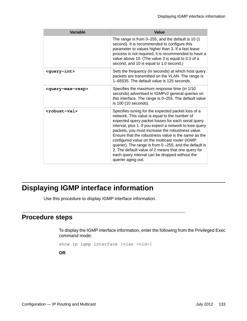
Variable ValueThe range is from 0–255, and the default is 10 (1second). It is recommended to configure thisparameter to values higher than 3. If a fast leaveprocess is not required, it is recommended to have avalue above 10. (The value 3 is equal to 0.3 of asecond, and 10 is equal to 1.0 second.)
<query-int> Sets the frequency (in seconds) at which host querypackets are transmitted on the VLAN. The range is1–65535. The default value is 125 seconds.
<query-max-resp> Specifies the maximum response time (in 1/10seconds) advertised in IGMPv2 general queries onthis interface. The range is 0–255. The default valueis 100 (10 seconds).
<robust-val> Specifies tuning for the expected packet loss of anetwork. This value is equal to the number ofexpected query packet losses for each serial queryinterval, plus 1. If you expect a network to lose querypackets, you must increase the robustness value.Ensure that the robustness value is the same as theconfigured value on the multicast router (IGMPquerier). The range is from 0 –255, and the default is2. The default value of 2 means that one query foreach query interval can be dropped without thequerier aging out.
Displaying IGMP interface informationUse this procedure to display IGMP interface information.
Procedure steps
To display the IGMP interface information, enter the following from the Privileged Execcommand mode:
show ip igmp interface [vlan <vid>]OR
Displaying IGMP interface information
Configuration — IP Routing and Multicast July 2012 133

show ip igmp <vid>
Variable definitionsThe following table describes the show ip igmp command variables.
Variable Value
[vid <vid>] Specifies the VLAN ID for which to display IGMP information.Range is 1-4094.
Job aidThe following table shows the field descriptions for the show ip igmp interfacecommand.
Field Description
VLAN Indicates the VLAN on which IGMP isconfigured.
Query Intvl Specifies the frequency (in seconds) atwhich host query packets are transmitted onthe interface.
Vers Specifies the version of IGMP configured onthis interface.
Oper Vers Specifies the version of IGMP running on thisinterface
Query MaxRspT Indicates the maximum query response time(in tenths of a second) advertised in IGMPv2queries on this interface.
Wrong Query Indicates the number of queries receivedwhose IGMP version does not match theInterface version. You must configure allrouters on a LAN to run the same version ofIGMP. Thus, if queries are received with thewrong version, a configuration error occurs.
Joins Indicates the number of times a groupmembership was added on this interface.
Robust Specifies the robust value configured forexpected packet loss on the interface.
LastMbr Query Indicates the maximum response time (intenths of a second) inserted into group-
IGMP snooping configuration using ACLI
134 Configuration — IP Routing and Multicast July 2012Comments? [email protected]

specific queries sent in response to leavegroup messages, and is also the amount oftime between group-specific querymessages. Use this value to modify the leavelatency of the network. A reduced valueresults in reduced time to detect the loss ofthe last member of a group. This does notapply if the interface is configured forIGMPv1.
Send Query Indicates whether the ip igmp send-queryfeature is enabled or disabled. Values areYES of NO. Default is disabled.
The following table shows the field descriptions for the show ip igmp command.
Field DescriptionSnooping Indicates whether snooping is enabled or
disabled.
Proxy Indicates whether proxy snoop is enabled ordisabled.
Robust Value Indicates the robustness value configured forexpected packet loss on the interface.
Query Time Indicates the frequency (in seconds) at whichhost query packets are transmitted on theinterface.
IGMPv1 Static Router Ports Indicates the IGMPv1 static mrouter ports.
IGMPv2 Static Router Ports Indicates the IGMPv2 static mrouter ports.
Send Query Indicates whether the ip igmp send-queryfeature is enabled or disabled. Values areYES or NO. Default is disabled.
Displaying IGMP group membership informationDisplay the IGMP group membership information to show the learned multicast groups andthe attached ports.
Displaying IGMP group membership information
Configuration — IP Routing and Multicast July 2012 135

Procedure steps
To display IGMP group information, enter the following from the Privileged Execcommand mode:
show ip igmp group [count] [group <A.B.C.D>] [member-subnet<A.B.C.D>/<0-32>]OR
show ip multicast membership <vid>
Variable definitionsThe following table describes the command variables.
Variable Valuecount Displays the number of IGMP group entries.
group <A.B.C.D> Displays group information for the specified group.
member-subnet<A.B.C.D>/<0–32>
Displays group information for the specified member subnet.
<vid> Specifies the VLAN for which to display IP Multicastmemberships.
Job aidThe following table shows the field descriptions for the show ip igmp group command
Field Description
Group Address Indicates the multicast group address.
VLAN Indicates the VLAN interface on which the group exists.
Member Address Indicates the IP address of the IGMP receiver (host or IGMPreporter). The IP address is 0.0.0.0 if the type is static.
Expiration Indicates the time left before the group report expires. Thisvariable Is updated upon receiving a group report.
Type Specifies the type of membership: static or dynamic
IGMP snooping configuration using ACLI
136 Configuration — IP Routing and Multicast July 2012Comments? [email protected]

In Port Identifies the member port for the group. This is the port on whichgroup traffic is forwarded, and in those cases where the type isdynamic, it is the port on which the IGMP join was received.
The following table shows the field descriptions for the show ip multicast membershipcommand.
Field DescriptionMulticast GroupAddress
Indicates the multicast group address.
In Port Indicates the physical interface or the logical interface (VLAN) thatreceived group reports from various sources.
Displaying IGMP cache Information using ACLIUse this procedure to show the learned multicast groups in the cache and the IGMPv1 versiontimers.
NOTE: Using the show ip igmp cache command may not display the expected results in someconfigurations. If the expected results are not displayed, use the show ip igmp groupcommand to view the information.
Procedure steps
To display the IGMP cache information, enter the following from the PriviligedExecutive command mode:
show ip igmp cacheJob aidThe following table shows the field descriptions for the show ip igmp cache command.
Variable ValueGroup Address Indicates the multicast group address.
VLAN ID Indicates the VLAN interface on which thegroup exists.
Last Reporter Indicates the last IGMP host to join thegroup.
Expiration Indicates the group expiration time (inseconds).
V1 Host Timer Indicates the time remaining until the localrouter assumes that no IGMP version 1
Displaying IGMP cache Information using ACLI
Configuration — IP Routing and Multicast July 2012 137

Variable Valuemembers exist on the IP subnet attached tothe interface. Upon hearing an IGMPv1membership report, this value is reset to thegroup membership timer.When the time remaining is nonzero, thelocal interface ignores any IGMPv2 Leavemessages that it receives for this group.
Type Indicates whether the entry is learneddynamically or is added statically.
Flushing the IGMP router table using ACLIUse this procedure to flush the IGMP router table.
Procedure steps
To flush the router table, enter the following from the Global Configuration mode
ip igmp flush vlan <vid> {grp-member|mrouter}Variable definitions
Variable Value{grp-member|mrouter} Flushes the table specified by type.
Configuring IGMP router alert on a VLAN using ACLIUse this command to enable the router alert feature. This feature instructs the router to dropcontrol packets that do not have the router-alert flag in the IP header.
ATTENTION
To maximize your network performance, it is recommended that you set the router alert optionaccording to the version of IGMP currently in use:
• IGMPv1 — Disable
• IGMPv2 — Enable
• IGMPv3 — Enable
IGMP snooping configuration using ACLI
138 Configuration — IP Routing and Multicast July 2012Comments? [email protected]

Procedure steps
To configure the router alert option on a VLAN, enter the following from the VLANInterface Configuration mode:
[default] [no] ip igmp router-alertVariable definitions
Variable Valuedefault Disables the router alert option.
no Disables the router alert option.
Configuring IGMP router alert on a VLAN using ACLI
Configuration — IP Routing and Multicast July 2012 139

IGMP snooping configuration using ACLI
140 Configuration — IP Routing and Multicast July 2012Comments? [email protected]

Chapter 14: IP routing configuration usingEnterprise Device Manager
This chapter describes the procedures you can use to configure routable VLANs using Enterprise DeviceManager.
The Avaya Ethernet Routing Switch 2500 Series, are Layer 3 switches. This means that a regular Layer2 VLAN becomes a routable Layer 3 VLAN if an IP address is attached to the VLAN. When routing isenabled in Layer 3 mode, every Layer 3 VLAN is capable of routing as well as carrying the managementtraffic. You can use any Layer 3 VLAN instead of the Management VLAN to manage the switch.
Prerequisites• Open one of the supported Web browsers.• Access the switch.• Click the Configuration arrowhead to open the navigation tree.
IP routing configuration proceduresTo configure IP routing on VLANs, perform the following steps:
1. Enable IP routing globally.
2. Assign an IP address to a specific VLAN.
In the preceding procedure, you are not required to enable IP routing as the first step. You canconfigure all IP routing parameters on the Avaya Ethernet Routing Switch 2500 Series, beforeyou enable routing on the switch.
Configuration — IP Routing and Multicast July 2012 141

Navigation• Configuring global IP routing status and ARP lifetime on page 142
• Configuring an IP address and enabling routing for a VLAN on page 143
• Displaying configured IP Addresses on page 144
Configuring global IP routing status and ARP lifetimeUse the following procedure to enable and disable global routing at the switch level. By default,routing is disabled.
You can also use this procedure to configure the ARP lifetime on the switch.
Procedure steps
1. From the navigation tree, click IP.
2. In the IP routing tree, click IP.
The globals tab appears.
3. In the Forwarding box, select the option to enable routing.
4. In the ARPLIfeTime box, modify the value to configure the ARP lifetime.
5. Click Apply.
Variable definitionsThe following table describes the Globals tab fields.
Variable ValueForwarding Indicates whether routing is enabled (forwarding) or disabled
(nonforwarding) on the switch.
DefaultTTL Indicates the default time-to-live (TTL) value for a routed packet.TTL is the maximum number of seconds elapsed before a packetis discarded. The value is inserted in the TTL field of the IP headerof datagrams when one is not supplied by the transport layerprotocol. The TTL field is also reduced by one each time the
IP routing configuration using Enterprise Device Manager
142 Configuration — IP Routing and Multicast July 2012Comments? [email protected]

Variable Valuepacket passes through a router. Range is 1-255. Default value is64 seconds.
ReasmTimeout Indicates the maximum number of seconds that receivedfragments are held while they await reassembly at this entity.Default value is 60 seconds.
ARPLifeTime Specifies the lifetime in minutes of an ARP entry within thesystem. Range is 5-360. Default is 360 minutes.
Configuring an IP address and enabling routing for aVLAN
Use the following procedure to configure an IP address and enable routing for a VLAN.
Prerequisites
• Enable routing globally on the switch.
Procedure steps
1. From the navigation tree, click VLAN.
2. In the VLAN navigation tree, click VLANs.
3. In the work area, select a VLAN.
4. On the toolbar, click IP.
The IP, VLAN dialog box appears with the IP Address tab selected.
5. On the toolbar, click Insert.
The Insert IP Address dialog box appears.
6. Type the IP address, subnet mask, and MAC address offset in the fields provided.
7. Click Insert.
Configuring an IP address and enabling routing for a VLAN
Configuration — IP Routing and Multicast July 2012 143

Variable definitionsThe following table describes the IP Address tab fields.
Variable ValueIpAddress Specifies the IP address to associate with the selected VLAN.
NetMask Specifies the subnet mask.
VlanId Specifies the VLAN ID. A value of -1 indicates that the VLAN IDis ignored.
MacOffset Specifies the value used to calculate the VLAN MAC address,which is offset from the switch MAC address. The valid range is1-256. Specify the value 1 for the Management VLAN only. If noMAC offset is specified, the switch applies one automatically.
Displaying configured IP AddressesUse the following procedure to display configured IP addresses on the switch.
Procedure steps
1. From the navigation tree, click IP.
2. In the IP routing tree, click IP.
3. In the work area, click the Addresses tab.
Variable definitionsThe following table describes the Addresses tab fields.
Variable ValueIfIndex Specifies the VLAN ID.
IpAddress Specifies the associated IP address.
NetMask Specifies the subnet mask.
BcastAddrFormat Specifies the format of the IP broadcast address.
IP routing configuration using Enterprise Device Manager
144 Configuration — IP Routing and Multicast July 2012Comments? [email protected]

Variable ValueReasmMaxSize Specifies the size of the largest IP datagram that this entity can
reassemble from fragmented datagrams received on thisinterface.
VlanId Specifies the VLAN ID number. A value of -1 indicates that theVLAN ID is ignored.
MacOffset Specifies the value used to calculate the VLAN MAC address,which is offset from the switch MAC address.
Displaying configured IP Addresses
Configuration — IP Routing and Multicast July 2012 145

IP routing configuration using Enterprise Device Manager
146 Configuration — IP Routing and Multicast July 2012Comments? [email protected]

Chapter 15: Static route configurationusing Enterprise DeviceManager
This chapter describes the procedures you can use to configure static routes using Enterprise DeviceManager.
Prerequisites• Open one of the supported Web browsers.• Access the switch.• Click the Configuration arrowhead to open the navigation tree.
Navigation• Configuring static routes on page 147
• Displaying IP routes on page 149
• Filtering route information on page 150
• Displaying TCP information for the switch on page 151
• Displaying TCP Connections on page 152
• Displaying TCP Listeners on page 152
• Displaying UDP endpoints on page 153
Configuring static routesUse the following procedure to configure static routes for the switch.
Configuration — IP Routing and Multicast July 2012 147
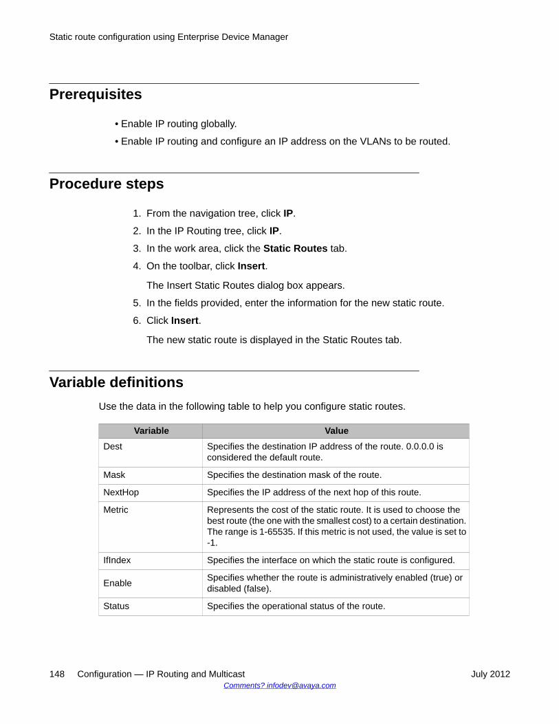
Prerequisites
• Enable IP routing globally.
• Enable IP routing and configure an IP address on the VLANs to be routed.
Procedure steps
1. From the navigation tree, click IP.
2. In the IP Routing tree, click IP.
3. In the work area, click the Static Routes tab.
4. On the toolbar, click Insert.
The Insert Static Routes dialog box appears.
5. In the fields provided, enter the information for the new static route.
6. Click Insert.
The new static route is displayed in the Static Routes tab.
Variable definitionsUse the data in the following table to help you configure static routes.
Variable ValueDest Specifies the destination IP address of the route. 0.0.0.0 is
considered the default route.
Mask Specifies the destination mask of the route.
NextHop Specifies the IP address of the next hop of this route.
Metric Represents the cost of the static route. It is used to choose thebest route (the one with the smallest cost) to a certain destination.The range is 1-65535. If this metric is not used, the value is set to-1.
IfIndex Specifies the interface on which the static route is configured.
Enable Specifies whether the route is administratively enabled (true) ordisabled (false).
Status Specifies the operational status of the route.
Static route configuration using Enterprise Device Manager
148 Configuration — IP Routing and Multicast July 2012Comments? [email protected]

Displaying IP routesUse the following procedure to display the different routes known to the switch.
Routes are not be displayed until at least one port in the VLAN has link.
Procedure steps
1. From the navigation tree, click IP.
2. In the IP navigation tree, click IP.
3. In the work area, click the Routes tab.
Variable definitionsUse the data in the following table to help you understand the IP routes.
Variable ValueDest Specifies the destination address of the route.
Mask Specifies the subnet mask for the route.
NextHop Specifies the next hop for the route.
HopOrMetric Specifies the metric associated with the route.
Interface Specifies the interface associated with the route.
Proto Specifies the protocol associated with the route. For this release,options are local or static.
PathType Specifies the route path type:
• i: indirect
• d: direct
• B: best
• U: unresolved
Pref Specifies the preference value associated with the route.
Displaying IP routes
Configuration — IP Routing and Multicast July 2012 149

Filtering route informationUse the following procedure to filter the routes displayed in the Routes tab to display only thedesired switch routes.
Procedure steps
1. From the navigation tree, click IP.
2. In the IP tree, click IP.
3. Select the Routes tab.
4. Click Filter.
The Filter dialog box appears.
5. Using the fields provided, set the filter for the tab.
6. Click Filter.
Variable definitionsUse the data in the following table to help you filter route information.
Variable ValueCondition When using multiple filter expressions on the tab, this is the
condition that is used to join them together.
Ignore Case Indicates whether filters are case sensitive or insensitive.
Column Indicates the type of criteria to apply to values used for filtering.
All Records Select this check box to clear any filters and display all rows.
Dest Select this check box and enter a value to filter on the routedestination value.
Mask Select this check box and enter a value to filter on the routedestination subnet mask value.
NextHop Select this check box and enter a value to filter on the route nexthop value.
HopOrMetric Select this check box and enter a value to filter on the hop countor metric of the route.
Static route configuration using Enterprise Device Manager
150 Configuration — IP Routing and Multicast July 2012Comments? [email protected]

Variable ValueInterface Select this check box and enter a value to filter on the interface
associated with the route.
Proto Select this check box and enter a value to filter on the routeprotocol.
PathType Select this check box and enter a value to filter on the route pathtype.
Pref Select this check box and enter a value to filter on the routepreference value.
Displaying TCP information for the switchUse the following procedure to display Transmission Control Protocol (TCP) information forthe switch.
Procedure steps
1. From the navigation tree, click IP.
2. In the IP Routing tree, click TCP/UDP.
Variable definitionsUse the data in the following table to understand the TCP information for the switch.
Variable ValueRtoAlgorithm Specifies the algorithm used to determine the timeout value used
for retransmitting unacknowledged octets.
RtoMin Specifies the minimum value permitted by a TCP implementationfor the retransmission timeout, measured in milliseconds.
RtoMax Specifies the maximum value permitted by a TCP implementationfor the retransmission timeout, measured in milliseconds.
MaxConn Specifies the limit on the total number of TCP connections thatthe entity can support. In entities where the maximum number ofconnections is dynamic, this object contains the value -1.
Displaying TCP information for the switch
Configuration — IP Routing and Multicast July 2012 151

Displaying TCP ConnectionsUse the following procedure to display information about the current TCP connections that theswitch maintains.
Procedure steps
1. From the navigation tree, click IP.
2. In the IP Routing tree, click TCP/UDP.
3. In the work area, click the TCP Connections tab.
Variable definitionsUse the data in the following table to understand the TCP connections.
Variable ValueLocalAddressType Specifies the local IP address type for this TCP connection.
LocalAddress Specifies the local IP address for this TCP connection. In the caseof a connection in the listen state, which is willing to acceptconnections for any IP interface associated with the node, thevalue 0.0.0.0 is used.
LocalPort Specifies the local port number for this TCP connection.
RemAddressType Specifies the remote IP address type for this TCP connection.
RemAddress Specifies the remote IP address for this TCP connection.
RemPort Specifies the remote port number for this TCP connection.
State Specifies the state of this TCP connection.
Displaying TCP ListenersUse the following procedure to display information about the current TCP listeners on theswitch.
Static route configuration using Enterprise Device Manager
152 Configuration — IP Routing and Multicast July 2012Comments? [email protected]

Procedure steps
1. From the navigation tree, click IP.
2. In the IP Routing tree, click TCP/UDP.
3. In the work area, click the TCP Listeners tab.
Variable definitionsUse the data in the following table to understand the information about the current TCPlisteners..
Variable ValueLocalAddressType Specifies the IP address type of the local TCP listener.
LocalAddress Specifies the local IP address of the TCP listener. The value ofthis field can be represented in three possible ways, dependingon the characteristics of the listening application:
1. For an application willing to accept both IPv4 and IPv6datagrams, the value of this object is a zero-length octetstring, and the value of the corresponding LocalAddressTypefield is unknown.
2. For an application willing to accept either IPv4 or IPv6datagrams, the value of this object must be 0.0.0.0 or ::, withthe LocalAddressType identifying the supported addresstype.
3. For an application that is listening for data destined only to aspecific IP address, the value of this object is the specificlocal address, with LocalAddressType identifying thesupported address type.
LocalPort Specifies the local port number for this TCP connection
Displaying UDP endpointsUse the following procedure to display information about the UDP endpoints currentlymaintained by the switch.
Displaying UDP endpoints
Configuration — IP Routing and Multicast July 2012 153

Procedure steps
1. From the navigation tree, click IP.
2. Click TCP/UDP.
3. Select the UDP Endpoints tab.
4. Click Refresh to immediately refresh the information displayed.
Variable definitionsUse the data in the following table to understand the UDP endpoints.
Field DescriptionLocalAddressType Specifies the local address type (IPv6 or IPv4).
LocalAddress Specifies the local IP address for this UDP listener. In the caseof a UDP listener that accepts datagrams for any IP interfaceassociated with the node, the value 0.0.0.0 is used. The valueof this field can be represented in three possible ways:
1. For an application willing to accept both IPv4 and IPv6datagrams, the value of this object is a zero-length octetstring, and the value of the correspondingLocalAddressType field is unknown.
2. For an application willing to accept either IPv4 or IPv6datagrams, the value of this object must be 0.0.0.0 or ::,with the LocalAddressType identifying the supportedaddress type.
3. For an application that is listening for data destined only toa specific IP address, the value of this object is the addressfor which this node is receiving packets, withLocalAddressType identifying the supported addresstype.
LocalPort Specifies the local port number for this UDP listener.
RemoteAddressType Displays the remote address type (IPv6 or IPv4).
RemoteAddress Displays the remote IP address for this UDP endpoint. Ifdatagrams from all remote systems are to be accepted, thisvalue is a zero-length octet string. Otherwise, the address of theremote system from which datagrams are to be accepted (or towhich all datagrams are to be sent) is displayed with theRemoteAddressType identifying the supported address type.
Static route configuration using Enterprise Device Manager
154 Configuration — IP Routing and Multicast July 2012Comments? [email protected]

Field Description
RemotePort Displays the remote port number. If datagrams from all remotesystems are to be accepted, this value is zero.
Instance Distinguishes between multiple processes connected to thesame UDP endpoint.
Process Displays the ID for the UDP process.
Displaying UDP endpoints
Configuration — IP Routing and Multicast July 2012 155

Static route configuration using Enterprise Device Manager
156 Configuration — IP Routing and Multicast July 2012Comments? [email protected]

Chapter 16: DHCP relay configurationusing Enterprise DeviceManager
This chapter describes the procedures you can use to configure DHCP relay using Enterprise DeviceManager.
Prerequisites• Enable IP routing globally.
• Enable IP routing and configure an IP address on the VLAN to be set as the DHCP relayagent.
• Ensure that a route (local or static) to the destination DHCP server is available on theswitch.
DHCP relay configuration proceduresTo configure DHCP using Enterprise Device Manager, perform the following steps:
1. Specify DHCP relay configuration.
2. Specify the remote DHCP server as the destination.
3. Enable DHCP relay on the VLAN.
Navigation• Enabling DHCP Forwarding on page 158
• Disabling DHCP Forwarding on page 159
• Configuring DHCP parameters on a VLAN on page 161
Configuration — IP Routing and Multicast July 2012 157

• Displaying and graphing DHCP counters on a VLAN on page 162
• Configuring DHCP Relay on page 159
• Configuring DHCP parameters on a VLAN on page 161
• Displaying and graphing DHCP counters on a VLAN on page 162
Enabling DHCP Forwarding Use the following procedure to enable DHCP forwarding.
Prerequisites
• Enable IP routing globally.• Enable IP Routing and configure an IP address on the VLAN to be set as the DHCP relay
agent.• Ensure that a route (local or static) to the destination DHCP server is available on the
switch.
Procedure steps
1. From the navigation tree, double-click IP.2. In the IP Routing tree, click DHCP Relay.3. In the work area, click the DHCP Globals tab.4. Select the following checkbox:
• DhcpForwardingEnabled5. On the toolbar, click Apply.
Configuring DHCP Forwarding maximum frame size globally usingEDM
You can specify the maximum frame size the DHCP relay agent can forward to the DHCPserver.
While the switch implementation permits configuration of the maximum DHCP packet size upto 1536 bytes, the default maximum size is 576 bytes.
Use the following procedure to configure DHCP Forwarding maximum frame size.
Procedure steps
1. From the navigation tree, double-click IP.2. In the IP Routing tree, click DHCP Relay.
DHCP relay configuration using Enterprise Device Manager
158 Configuration — IP Routing and Multicast July 2012Comments? [email protected]

3. In the work area, click the DHCP Globals tab.4. In the DhcpForwardingMaxFrameLength box, enter the frame length as a value
between 576 and 1536 bytes.
Note:The default value is 576 bytes.
5. On the toolbar, click Apply.
Disabling DHCP ForwardingUse the following procedure to disable DHCP forwarding.
Prerequisites
• Open one of the supported Web browsers.
• Access the switch.
• Click the Configuration arrowhead to open the navigation tree.
Procedure steps
1. From the navigation tree, click IP.
2. In the IP Routing tree, click DHCP.
3. On the DHCP Relay Global tab, click the DhcpForwardingEnabled check box toclear it.
4. On the toolbar, Click Apply.
Configuring DHCP RelayUse this procedure to configure DHCP Relay.
Procedure steps
1. From the navigation tree, double-click IP.2. In the IP Routing tree, double-click DHCP Relay.
Disabling DHCP Forwarding
Configuration — IP Routing and Multicast July 2012 159

3. In the work area, click the DHCP Relay tab.
The DHCP Relay tab appears.4. Click Insert.
The Insert DHCP Relay dialog box appears.5. In the AgentAddr box, type the IP address of the local VLAN to serve as the DHCP
relay agent.6. In the ServerAddr box, type the remote DHCP Server IP address.7. Ensure the Enable check box is selected.8. In the Mode section, click the desired DHCP relay mode.9. Click Insert.
The new DHCP entry appears in the DHCP Relay tab.
Variable definitions
Variable Value
AgentAddr The IP address of the local VLAN serving as the DHCP relayagent.
ServerAddr The IP address of the remote DHCP server.
Enable Enables (selected) or disables (cleared) DHCP relay.
Mode Indicates whether the relay instance applies for BOOTP packets,DHCP packets, or both.
Configuring DHCP Relay with Option 82 globally usingEDM
Use this procedure to enable DHCP Relay Option 82 globally.
Prerequisites
• Enable IP Routing globally.• Enable IP Routing and configure an IP address on the VLAN to be set as the DHCP Relay
agent.• Enable DHCP Forwarding• Ensure that a route, either local or static, is available on the switch to the destination
DHCP server.
DHCP relay configuration using Enterprise Device Manager
160 Configuration — IP Routing and Multicast July 2012Comments? [email protected]

Procedure steps
1. From the navigation tree, double-click IP.2. In the IP Routing tree, click DHCP Relay.3. In the work area, click the DHCP Globals tab.4. Select the DhcpForwardingOption82Enabled check box.5. On the toolbar, click Apply.
Configuring DHCP parameters on a VLANUse the following procedure to configure the DHCP relay parameters on a VLAN.
Procedure steps
1. From the navigation tree, click VLAN.
2. In the VLAN tree, click VLANs .
3. On the Basic tab, select the VLAN for which DHCP relay is to be configured.
4. On the toolbar, click IP.
The IP, VLAN dialog box appears.
5. Select the DHCP tab.
6. To configure the DHCP relay parameters, modify the values in the fields provided,as required.
7. Click Apply.
Variable definitionsUse the data in the following table to help you configure DHCP on VLANs.
Variable DescriptionEnable Specifies whether DHCP relay is enabled or disabled.
MinSec Indicates the min-sec value. The switch immediately forwards aBootP/DHCP packet if the secs field in the BootP/DHCP packetheader is greater than the configured min-sec value; otherwise,the packet is dropped.
Configuring DHCP parameters on a VLAN
Configuration — IP Routing and Multicast July 2012 161

Variable DescriptionMode Specifies the type of packets this VLAN interface forwards: BootP,
DHCP, or both.
AlwaysBroadcast Specifies whether DHCP Reply packets are broadcast to theDHCP clients on this VLAN interface.
ClearCounters Specifies to clear the DHCP relay counters for the VLAN.
CounterClearTime Specifies the last time the counter values in this entry were resetto 0.
Configuring DHCP Relay with Option 82 for a VLAN usingEDM
Use this procedure to configure DHCP Relay with Option 82 for a VLAN.
Prerequisites
• Enable IP routing globally.• On the VLAN: enable IP Routing and configure an IP address to be set as the DHCP
Relay agent.• Ensure that a route, either local or static, is available on the switch to the destination
DHCP server.
Procedure steps
1. From the navigation tree, double-click IP.2. In the IP Routing tree, click DHCP Relay.3. In the work area, click the DHCP Relay-VLAN tab.4. In the table, double-click the cell below the Option82Enabled column to edit.5. Select one of the following values from the list:
• true to enable DHCP Relay with Option 82 for the VLAN• false to disable DHCP Relay with Option 82 for the VLAN
6. On the toolbar, click Apply.
Displaying and graphing DHCP counters on a VLANUse the following procedure to display and graph the current DHCP counters on a VLAN.
DHCP relay configuration using Enterprise Device Manager
162 Configuration — IP Routing and Multicast July 2012Comments? [email protected]

Procedure steps
1. From the navigation tree, click VLAN .
2. In the VLAN tree, click VLANs
3. Select the VLAN for which DHCP is configured.
4. Click IP.
The IP, VLAN dialog box appears.
5. Select the DHCP tab.
6. Click Graph.
The DHCP Stats dialog box appears.
7. Use the buttons provided to graph selected DHCP counter information.
Job aidThe following table describes the DHCP Stats dialog box fields.
Field DescriptionNumRequests Indicates the number of DHCP requests.
NumReplies Indicates the number of DHCP replies.
Assigning a DHCP Relay Option 82 subscriber ID to a portusing EDM
Use the following procedure to assign a DHCP Relay Option 82 subscriber ID to a port toassociate an alphanumeric character string with the Option 82 function for the port.
Prerequisites
• Enable IP Routing globally.• On the VLAN: enable IP Routing and configure an IP address to be set as the DHCP
Relay agent.• Ensure that a route, either local or static, is available on the switch to the destination
DHCP server.
Assigning a DHCP Relay Option 82 subscriber ID to a port using EDM
Configuration — IP Routing and Multicast July 2012 163
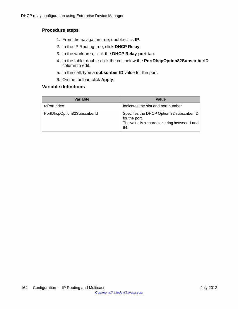
Procedure steps
1. From the navigation tree, double-click IP.2. In the IP Routing tree, click DHCP Relay.3. In the work area, click the DHCP Relay-port tab.4. In the table, double-click the cell below the PortDhcpOption82SubscriberID
column to edit.5. In the cell, type a subscriber ID value for the port.6. On the toolbar, click Apply.
Variable definitions
Variable ValuercPortIndex Indicates the slot and port number.
PortDhcpOption82SubscriberId Specifies the DHCP Option 82 subscriber IDfor the port.The value is a character string between 1 and64.
DHCP relay configuration using Enterprise Device Manager
164 Configuration — IP Routing and Multicast July 2012Comments? [email protected]

Chapter 17: DHCP Server configurationusing Enterprise DeviceManager
If you have no separate DHCP Server or other device available to provide the service to local hosts, youcan use the procedures in this chapter to configure the DHCP Server feature to provide and manage clientIPv4 addresses in your network and eliminate manual TCP/IP configuration.
Please note that the procedures in this chapter assume a single VLAN configuration. For configurationsin which there is only one VLAN (VLAN 1) on the switch, and where the Switch IP Address is in the sameVLAN as the new IP Address Pool that is being configured, routing (IP Forwarding) does not need to beenabled.
Enabling DHCP Server using EDMUse the following procedure to enable DHCP Server and specify the global DHCP Server leaseexpiry time.
PrerequisitesRequired for a single VLAN configuration:
• Define at least one IP address pool with a network mask• Enable DHCP on TCP/IP interface• Configure valid IPv4 address configuration on the DHCP server so it can offer an address
to the client. NOTE: Because DHCP Server on the switch is, by default, bound to theswitch Management VLAN, the DHCP service uses the switch or stack IP.
Required when adding a second or subsequent VLAN to which you want to assign DHCPServer pools:
• Enable IP routing/forwarding on the switch or stack
Procedure steps
1. In the navigation tree, click IP.2. In the IP tree, click DHCP Server.3. On the DHCP Server Globals tab, select the ServerEnable checkbox.4. In the Server Lease field, select the Days/Hours/Minutes checkbox to set the
lease time or select the Infinite checkbox.
Configuration — IP Routing and Multicast July 2012 165

5. If selecting a lease time, enter a value for the DHCP Server lease expiry time, oraccept the default of 1 day.
6. On the toolbar, click Apply.Note: You can enable either DHCP server or DHCP Snooping, they do not operate together.
Variable definitions
Variable ValueServer Enable Enable or disable DHCP Server.
The DHCP Server default is disabled.
ServerLease The system uses this lease time for addresses assigned froma pool that does not have a lease time setting.Specify a global lease expiry time:
• Days — 0 to 49710
• Hours — 0 to 23
• Minutes — 0 to 59
The infinite lease expiry time is 4294967295 seconds.
Reference —DHCP Server default settingsWhen you enable DHCP Server, the default settings are as follows:• IP address scope based on the switch or stack Management IP address• Mask in the Management VLAN. EXAMPLE: If the switch management address is
192.168.1.1 and the net mask is 255.255.255.0 (default IP) then Pool 1 is 192.168.1.3through 192.168.1.254 in VLAN 1.
• Operates at the global switch or stack level. Devices on all ports in the VLAN are assignedan address scope that can participate in IP address lease assignment
• Pool options are set to 0. An administrator must manually set each parameter that the DHCPServer is required to support.
Displaying DHCP Server Pool using EDMUse the following procedure to view DHCP Server Pool information.
Procedure steps
1. In the navigation tree, click IP2. In the IP tree, click DHCP Server.3. Click the DHCP Server Pool tab.
DHCP Server configuration using Enterprise Device Manager
166 Configuration — IP Routing and Multicast July 2012Comments? [email protected]

Variable definitions
Variable ValueName The unique DHCP Server Pool name.
Lease The lease expiry time in:
• Days from 1–49710
• Hours from 1–23
• Minutes from 1–59
• Infinite
• Use Global; no lease time set for this pool and the systemuses the global lease time.
StartAddress The first IP v4 IP address for the pool range.
EndAddress The last IPv4 IP address for the pool range.
MACAddress The MAC Address associated with a device for a statically-assigned DHCP Server host.
SubnetMask The subnet mask associated for this pool range.
VendorClassId The vendor-specific identifier that allows your DHCP Server toreceive vendor-specific configuration or identificationinformation for clients.
VendorSpecificInfo The vendor class identifier allows DHCP clients and DHCPservers in your network to exchange vendor-specificinformation.
IpPhoneMcport A value from –1 to 65535 that specifies the UDP port that theIP Phone uses for registration. A value of –1 indicates that thisparameter is not included in the configuration.
IpPhoneL2qvlan A value from –1 to 4096 that specifies the 802.1Q VLAN ID. Avalue of –1 indicates that this parameter is not included in theconfiguration.
IpPhoneVlantest A value from –1 to 999 that specifies the number of secondsa phone will attempt to return to the previously known voiceVLAN. A value of –1 indicates that this parameter is notincluded in the configuration.
IpPhoneL2quad A value from –1 to 7 that specifies the Layer 2 audio priorityvalue. A value of –1 indicates that this parameter is notincluded in the configuration.
IpPhoneL2qsig A value from –1 to 7 that specifies the Layer 2 signaling priorityvalue. A value of –1 indicates that this parameter is notincluded in the configuration.
Displaying DHCP Server Pool using EDM
Configuration — IP Routing and Multicast July 2012 167

Configuring a DHCP Server Pool using EDMUse the following procedure to configure a DHCP Server address pool.
Procedure steps
1. In the navigation tree, click IP2. In the IP tree, click DHCP Server.3. Click the DHCP Server Pool tab.4. On the toolbar, click Insert.5. On the Insert DHCP Server Pool pane, enter the values to configure a pool.6. Do one of the following:
• click Insert to add the DHCP Server pool and return to the DHCP Server Pool tab• click Cancel to terminate the operation and return to the DHCP Server Pool
tab.7. On the DHCP Server Pool toolbar, click Refresh to display the new DHCP Server
Pool.
Note:If you require more than one IP address pool you must first create additional VLANs—aVLAN to associate with each additional IP address pool.
Variable definitions
Variable ValueMandatory parameters
Name Enter a unique DHCP Server Pool name up to 32 alpha-numeric characters long.If the value is greater than 0, it is an explicit setting for a specificaddress pool. Zero is a global value used for all pools that donot have addresses of the specified type configured. Globalentry types must be either may DNS or router.
Lease Specify a value for lease expiry time in:
• Days –from 1-49710
• Hours – from 1-23
• Minutes – from 1-59
DHCP Server configuration using Enterprise Device Manager
168 Configuration — IP Routing and Multicast July 2012Comments? [email protected]

Variable Value
• Infinite
• Use Global — no lease time is set for this pool and the systemuses the global lease time.
StartAddress Enter the first IPv4 IP address for the pool range.This address must be in the same class as the DHCP Serveraddress and must be less than or equal to the value ofEndAddress.
EndAddress Enter the last IPv4 IP address for the pool range.This address must be in the same classs as the DHCP Serveraddress and must be greater than or equal to the value ofStartAddress.If the value is equal to StartAddress, it describes a static IPDHCP Server host.
MACAddress Enter the MAC Address associated with a device for astatically-assigned DHCP Server host.If address pools contain start and end addresses that are notequal, this value is not used and has no effect.
SubnetMask Specifies the subnet mask associated for this address poolrange.
Router(s) Specifies the router(s) associated for this address pool range.If entering multiple routers, separate the entries withcommas.
Optional Parameters
DNS Server(s) Specifies the list of DNS servers.If entering multiple servers, separate the entries withcommas.
TFTP Server(s) Specifies the list of TFTP serversIf entering multiple servers, separate the entries withcommas.
SIP Server(s) Specifies the list of SIP serversIf entering multiple servers, separate the entries withcommas.
VendorClassId(60) Enter the vendor class identifier so your DHCP server canreceive vendor-specific configuration or identificationinformation for clients. If you are using this parameter andVendorSpecificInfo(43), a specific IP pool must be createdusing only these parameters, as well as the default values.Separate IP pools should be created with additional variablesas required.The minimum length for a vendor class identifier is 1 character.Entries are case-sensitive
Configuring a DHCP Server Pool using EDM
Configuration — IP Routing and Multicast July 2012 169

Variable ValueVendorSpecificInfo(43) Enter the vendor class identifier if DHCP clients and DHCP
servers in your network need to exchange vendor-specificinformation. If you are using this parameter andVendorClassID(60), a specific IP pool must be created usingonly these parameters, as well as the default values. SeparateIP pools should be created with additional variables asrequired.The minimum length for a vendor class identifier is 1 characterVendor specific options must be specified in the followingformat:<code>:<type>:<data>:<code>:<type>:<data><code>: 255, 0 and 255 are reserved and cannot be used.<type>: available types are str, octet, short, long, ip, iplist,ippairs, mtpt or raw. All the types have the same format asdescribed above, except raw which is a list of byte valuesseparated by white space. For example: 0x4 0xAC 0x11 0X41<data>: the actual data to be included. Cannot contain singlequotes.More than one code, type, data triplet can be specified, butmust be separated by ":" . The entire vendor options must beenclosed within single quotes.Entries are case sensitive.
Note:The DHCP Server IP address pool Option 176, Avaya IP Phones, feature supports onlyAvaya 4600 series IP phones for provisioning a number of parameters. When you createa DHCP Server IP Address Pool, Option 176 is automatically enabled with several defaultparameters, with the exception of the MCIPADD and TFTP Server IP addressinformation.
DHCP Server Option 43 vendor specific informationThe following table lists the code types supported with the DHCP Server Option-43 vendorspecific info command.
Name Code Type Descriptionsnmk 1 ip Subnet mask of the IP address to be allocated.
Default: natural mask corresponding to the IPaddress.The server does not issue IP addresses toclients on different subnets.
tmof 2 long Time offset from UTC, in seconds.
DHCP Server configuration using Enterprise Device Manager
170 Configuration — IP Routing and Multicast July 2012Comments? [email protected]
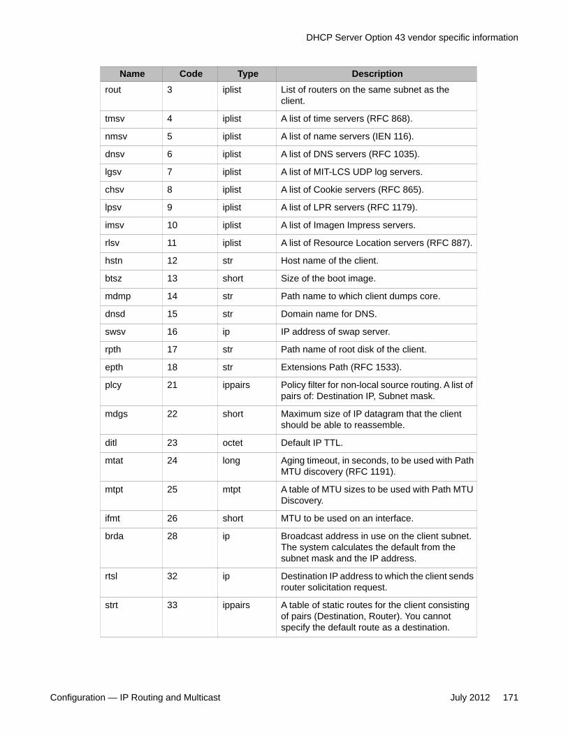
Name Code Type Descriptionrout 3 iplist List of routers on the same subnet as the
client.
tmsv 4 iplist A list of time servers (RFC 868).
nmsv 5 iplist A list of name servers (IEN 116).
dnsv 6 iplist A list of DNS servers (RFC 1035).
lgsv 7 iplist A list of MIT-LCS UDP log servers.
chsv 8 iplist A list of Cookie servers (RFC 865).
lpsv 9 iplist A list of LPR servers (RFC 1179).
imsv 10 iplist A list of Imagen Impress servers.
rlsv 11 iplist A list of Resource Location servers (RFC 887).
hstn 12 str Host name of the client.
btsz 13 short Size of the boot image.
mdmp 14 str Path name to which client dumps core.
dnsd 15 str Domain name for DNS.
swsv 16 ip IP address of swap server.
rpth 17 str Path name of root disk of the client.
epth 18 str Extensions Path (RFC 1533).
plcy 21 ippairs Policy filter for non-local source routing. A list ofpairs of: Destination IP, Subnet mask.
mdgs 22 short Maximum size of IP datagram that the clientshould be able to reassemble.
ditl 23 octet Default IP TTL.
mtat 24 long Aging timeout, in seconds, to be used with PathMTU discovery (RFC 1191).
mtpt 25 mtpt A table of MTU sizes to be used with Path MTUDiscovery.
ifmt 26 short MTU to be used on an interface.
brda 28 ip Broadcast address in use on the client subnet.The system calculates the default from thesubnet mask and the IP address.
rtsl 32 ip Destination IP address to which the client sendsrouter solicitation request.
strt 33 ippairs A table of static routes for the client consistingof pairs (Destination, Router). You cannotspecify the default route as a destination.
DHCP Server Option 43 vendor specific information
Configuration — IP Routing and Multicast July 2012 171

Name Code Type Descriptionarpt 35 long Timeout, in seconds, for ARP cache.
dttl 37 octet Default TTL of TCP.
kain 38 long Client TCP keepalive interval, in seconds.
nisd 40 str Domain name for NIS.
nisv 41 iplist A list of NIS servers
ntsv 42 iplist A list of NTP servers.
vend 43 str Vendor Specific Options—must be specified inthe following format:vend=<code>:<type>:<date>:<code>:<type>:<date>• <code> is an int 1 < <code> <255
Do not use 0 and 255, they are reserved.
• <type> can be str, octet, short, long, ip, ip list,ippairs, mtpt, or raw.All types have the same format describedabove, except raw, which is a list of typevalues separated by white space.Example for raw: 0x4 0xAC 0x11 ox41
• <data> is the actual data.Data cannot contain single quotes.
Syntax:You can specify more than one code, type, ordata triplets, but you must separate each by acolon (:).You must enclose the entire vendor optionswithin single quotes (').
nnsv 44 iplist A list of NetBIOS name servers (RFC 1001,1002).
ndsv 45 iplist A list of NetBIOS datagram distribution servers(RFC 1001, 1002).
nbnt 46 octet NetBIOS node type (RFC 1001, 1002).
nbsc 47 str NetBIOS scopt (RFC 1001, 1002).
xsfv 48 iplist A list of font servers of X Window system.
xdmn 49 iplist A list of display managers of X Windowsystem.
dht1 58 short Specifies when the client should startRENEWING.DEFAULT: 500
DHCP Server configuration using Enterprise Device Manager
172 Configuration — IP Routing and Multicast July 2012Comments? [email protected]
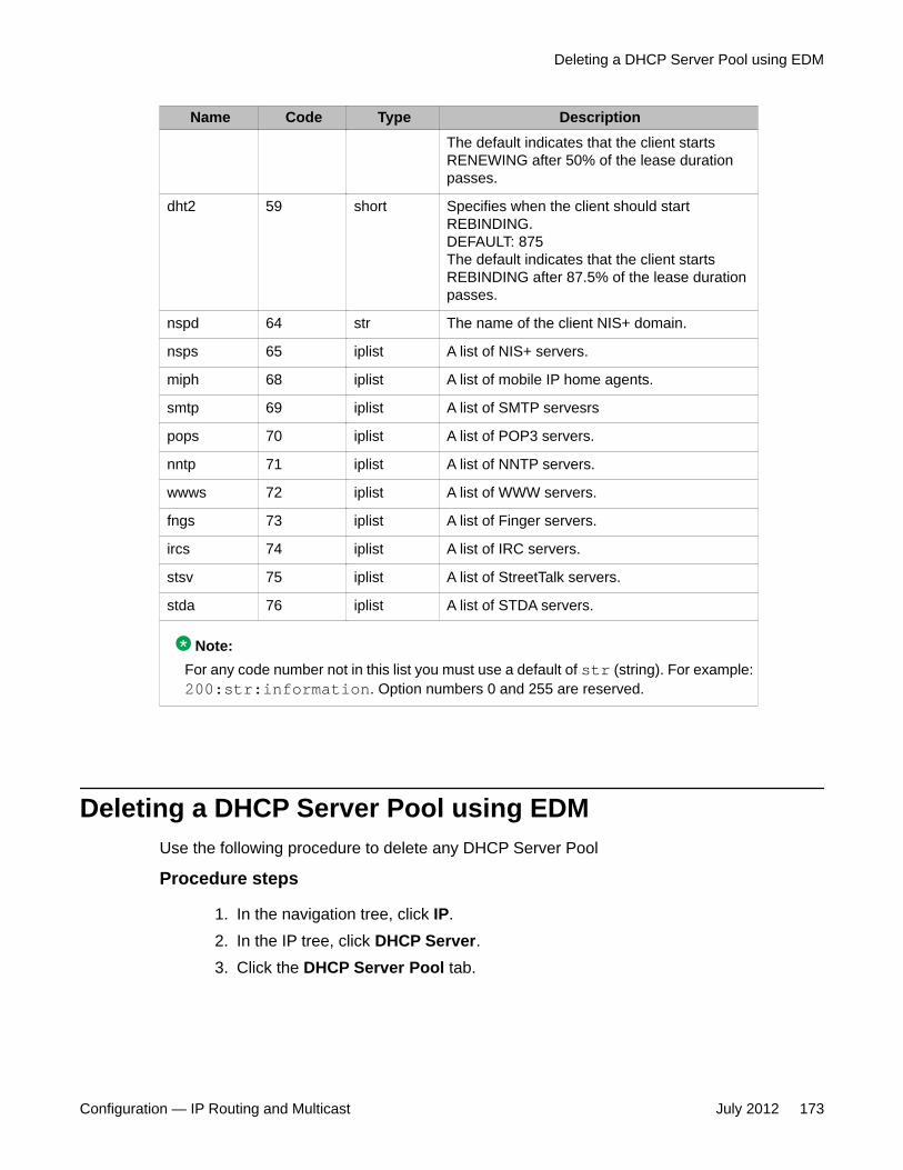
Name Code Type DescriptionThe default indicates that the client startsRENEWING after 50% of the lease durationpasses.
dht2 59 short Specifies when the client should startREBINDING.DEFAULT: 875The default indicates that the client startsREBINDING after 87.5% of the lease durationpasses.
nspd 64 str The name of the client NIS+ domain.
nsps 65 iplist A list of NIS+ servers.
miph 68 iplist A list of mobile IP home agents.
smtp 69 iplist A list of SMTP servesrs
pops 70 iplist A list of POP3 servers.
nntp 71 iplist A list of NNTP servers.
wwws 72 iplist A list of WWW servers.
fngs 73 iplist A list of Finger servers.
ircs 74 iplist A list of IRC servers.
stsv 75 iplist A list of StreetTalk servers.
stda 76 iplist A list of STDA servers.
Note:For any code number not in this list you must use a default of str (string). For example:200:str:information. Option numbers 0 and 255 are reserved.
Deleting a DHCP Server Pool using EDMUse the following procedure to delete any DHCP Server Pool
Procedure steps
1. In the navigation tree, click IP.2. In the IP tree, click DHCP Server.3. Click the DHCP Server Pool tab.
Deleting a DHCP Server Pool using EDM
Configuration — IP Routing and Multicast July 2012 173

4. In the Name column, click a DHCP Server Pool to delete.5. On the toolbar, click Delete.
Configuring DHCP Server Pool Options using EDMUse the following procedure to configure DHCP Server Pool options.
Procedure steps
1. In the navigation tree, click IP.2. In the IP tree, click DHCP Server.3. Click the DHCP Server Pool tab4. On the toolbar, click Options.5. On the DHCP Server Pool Options toolbar, click Insert.6. Use the fields and buttons on the DHCP Server Pool Options pane to configure
the DHCP Server Pool Options.7. Do one of the following:
• click Insert to add the DHCP Server Pool Options and return to the DHCP ServerPool Options tab.
• click Cancel to terminate the operation and return to the DHCP Server PoolOptions tab.
8. On the toolbar, click Apply to save your changes.
Variable definitions
Variable ValuePoolName Enter an IP address pool name up to 32 alphanumeric characters long.
You can define up to 32 separate pools.
Type Select one of the following server types to assign an IP address:
• DNS Server (6)- you can define a maximum of 8 DNS servers
• Router (3) - you can define a maximum of 8 global routers
• SIP Server (120 )- you can define a maximum of 8 SIP servers
• TFTP Server (150) - you can define a maximum of 8 TFTP servers
• IP Phone MC IP addr (176) - you can define a maximum of 8ipPhoneMcipadd servers
• IP Phone TFTP Server (176) - you can define a maximum of 8ipPhoneTftpsrvr servers
DHCP Server configuration using Enterprise Device Manager
174 Configuration — IP Routing and Multicast July 2012Comments? [email protected]

Variable ValueAddrType The ipv4 address type is auto-selected.
Address The DHCP Server IP address is the management IP address of theswitch or stack.
Deleting DHCP Server Pool Options using EDMUse the following procedure to delete DHCP Server Pool options.
Procedure steps
1. In the navigation tree, click IP.2. In the IP tree, click DHCP Server.3. Click the DHCP Server Pool tab.4. On the toolbar, click Options.5. In the Name column, select the pool you wish to delete the options for.6. On the toolbar, click Options.7. Within the DHCP Server Pool, select an option row to delete.
For example: Router, or DNS Server entry8. On the toolbar, click Delete.
Deleting DHCP Server Pool Options using EDM
Configuration — IP Routing and Multicast July 2012 175

DHCP Server configuration using Enterprise Device Manager
176 Configuration — IP Routing and Multicast July 2012Comments? [email protected]

Chapter 18: UDP broadcast forwardingconfiguration using EnterpriseDevice Manager
This chapter describes the procedures you can use to configure and manage UDP broadcast forwardingusing Enterprise Device Manager. UDP broadcast forwarding is a general mechanism for selectivelyforwarding limited UDP broadcasts received on an IP interface to a configured IP address.
Prerequisites to UDP broadcast forwarding configurationusing Enterprise Device Manager
• Enable IP routing globally.
• Enable IP routing and configure an IP address on the VLAN to be configured as a UDPforwarding interface.
• Ensure that a route (local or static) to the destination address is available on the switch.
UDP broadcast forwarding configuration proceduresTo configure UDP broadcast forwarding using Enterprise Device Manager, perform thefollowing steps:
1. Create UDP protocol entries that specify each UDP port and associated protocolthat you want to forward.
2. Create UDP forwarding entries that specify the destination address for each UDPport that you want to forward.
3. Add UDP forwarding entries to a UDP forwarding list (you can create up to 128 UDPforwarding lists.)
4. Apply UDP forwarding lists to local VLAN interfaces.
Configuration — IP Routing and Multicast July 2012 177
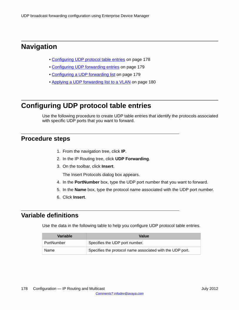
Navigation• Configuring UDP protocol table entries on page 178
• Configuring UDP forwarding entries on page 179
• Configuring a UDP forwarding list on page 179
• Applying a UDP forwarding list to a VLAN on page 180
Configuring UDP protocol table entriesUse the following procedure to create UDP table entries that identify the protocols associatedwith specific UDP ports that you want to forward.
Procedure steps
1. From the navigation tree, click IP.
2. In the IP Routing tree, click UDP Forwarding.
3. On the toolbar, click Insert.
The Insert Protocols dialog box appears.
4. In the PortNumber box, type the UDP port number that you want to forward.
5. In the Name box, type the protocol name associated with the UDP port number.
6. Click Insert.
Variable definitionsUse the data in the following table to help you configure UDP protocol table entries.
Variable ValuePortNumber Specifies the UDP port number.
Name Specifies the protocol name associated with the UDP port.
UDP broadcast forwarding configuration using Enterprise Device Manager
178 Configuration — IP Routing and Multicast July 2012Comments? [email protected]

Configuring UDP forwarding entriesUse the following procedure to configure individual UDP forwarding entries, which associateUDP forwarding ports with destination IP addresses.
Procedure steps
1. From the navigation tree, click IP.
2. In the IP Routing tree, click UDP Forwarding.
3. In the work area, click the Forwardings tab.
4. On the toolbar, click Insert.
The Insert Forwardings dialog box appears.
5. Specify a destination address for a selected port in the Forwardings dialog boxfields.
6. Click Insert.
Variable definitionsThe following table describes the Forwardings tab fields.
Variable ValueDestPort Specifies the port on which the UDP forwarding originates
(configured using the Protocols tab).
DestAddr Specifies the destination IP address.
Configuring a UDP forwarding listUse the following procedure to add the UDP port/destination forwarding entries (configured inthe Forwardings tab) to UDP forwarding lists. Each UDP forwarding list can contain multipleport/destination entries.
Configuring UDP forwarding entries
Configuration — IP Routing and Multicast July 2012 179

Procedure steps
1. From the navigation tree, click IP.
2. In the IP Routing tree, click UDP Forwarding.
3. In the work area, select the Forwarding Lists tab.
4. On the toolbar, click Insert.
The Insert Forwarding Lists dialog box appears.
5. In the Id box, assign a unique ID to the UDP forwarding list.
6. In the Name box, enter a unique name for the UDP forwarding list.
7. Beside the dimmed FwdIdList box, click the ellipsis [...] .
8. From the FwdIdList list, select the desired port/destination pairs.
9. Click Ok.
10. Click Insert.
Variable definitionsUse the data in the following table to help you configure a UDP forwarding list.
Variable ValueId The unique identifier assigned to the forwarding list.
Name The name assigned to the forwarding list.
FwdIdList The forwarding entry IDs associated with the port/server IP pairscreated using the Forwardings tab.
Applying a UDP forwarding list to a VLANUse the following procedure to assign a UDP forwarding list to a VLAN and to configure therelated UDP forwarding parameters for the VLAN.
UDP broadcast forwarding configuration using Enterprise Device Manager
180 Configuration — IP Routing and Multicast July 2012Comments? [email protected]
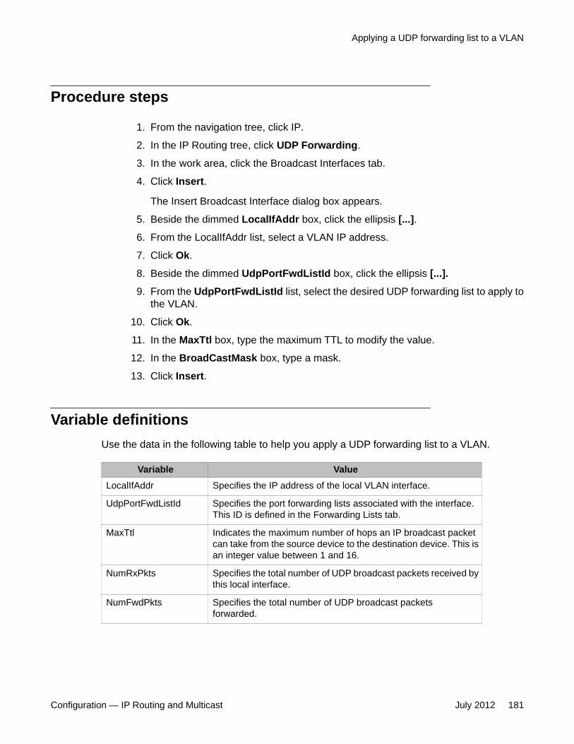
Procedure steps
1. From the navigation tree, click IP.
2. In the IP Routing tree, click UDP Forwarding.
3. In the work area, click the Broadcast Interfaces tab.
4. Click Insert.
The Insert Broadcast Interface dialog box appears.
5. Beside the dimmed LocalIfAddr box, click the ellipsis [...].
6. From the LocalIfAddr list, select a VLAN IP address.
7. Click Ok.
8. Beside the dimmed UdpPortFwdListId box, click the ellipsis [...].
9. From the UdpPortFwdListId list, select the desired UDP forwarding list to apply tothe VLAN.
10. Click Ok.
11. In the MaxTtl box, type the maximum TTL to modify the value.
12. In the BroadCastMask box, type a mask.
13. Click Insert.
Variable definitionsUse the data in the following table to help you apply a UDP forwarding list to a VLAN.
Variable ValueLocalIfAddr Specifies the IP address of the local VLAN interface.
UdpPortFwdListId Specifies the port forwarding lists associated with the interface.This ID is defined in the Forwarding Lists tab.
MaxTtl Indicates the maximum number of hops an IP broadcast packetcan take from the source device to the destination device. This isan integer value between 1 and 16.
NumRxPkts Specifies the total number of UDP broadcast packets received bythis local interface.
NumFwdPkts Specifies the total number of UDP broadcast packetsforwarded.
Applying a UDP forwarding list to a VLAN
Configuration — IP Routing and Multicast July 2012 181
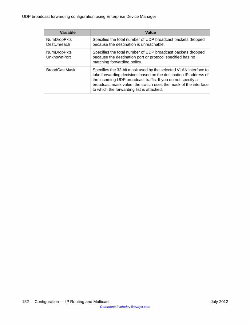
Variable ValueNumDropPktsDestUnreach
Specifies the total number of UDP broadcast packets droppedbecause the destination is unreachable.
NumDropPktsUnknownPort
Specifies the total number of UDP broadcast packets droppedbecause the destination port or protocol specified has nomatching forwarding policy.
BroadCastMask Specifies the 32-bit mask used by the selected VLAN interface totake forwarding decisions based on the destination IP address ofthe incoming UDP broadcast traffic. If you do not specify abroadcast mask value, the switch uses the mask of the interfaceto which the forwarding list is attached.
UDP broadcast forwarding configuration using Enterprise Device Manager
182 Configuration — IP Routing and Multicast July 2012Comments? [email protected]

Chapter 19: Static ARP and Proxy ARPconfiguration using EnterpriseDevice Manager
This chapter describes the procedures you can use to configure Static ARP, display ARP entries, andconfigure Proxy ARP using Enterprise Device Manager.
Navigation• Configuring static ARP entries on page 183
• Configuring Proxy ARP on page 184
Configuring static ARP entriesUse this procedure to configure static ARP entries for the switch.
Prerequisites
• Enable IP routing globally.
• Enable IP routing and configure an IP address on the target VLAN interface.
Procedure steps
1. From the navigation tree, click IP.
2. In the IP Routing tree, click IP.
3. In the work area, click the ARP tab.
4. On the toolbar, click Insert.
Configuration — IP Routing and Multicast July 2012 183
The Insert ARP dialog box appears.
5. Click Port in Vlan.
6. From the Port in VLAN list, select the VLAN to which you want to add the staticARP entry.
A VLAN dialog box appears listing all member ports.
7. In the VLAN dialog box, select the port for this ARP entry.
The Interface(vlanId:Port) field updates with the appropriate VLAN and portinformation
8. In the IPAddress box, type the IP address for the ARP entry.
9. In the MacAddress box, type the MAC address for the ARP entry.
10. Click Insert.
Variable definitionsUse the data in the following table to help you to configure static ARP entries.
Variable Value
Interface Specifies the VLAN and port to which the static ARP entry is beingadded.
MacAddress Specifies the MAC address of the device being set as a static ARPentry.
IpAddress Specifies the IP address of the device being set as a static ARPentry.
Type Specifies the type of ARP entry: static, dynamic, or local.
Configuring Proxy ARPUse the following procedure to configure proxy ARP on the switch. Proxy ARP allows the switchto respond to an ARP request from a locally attached host (or end station) for a remotedestination.
Static ARP and Proxy ARP configuration using Enterprise Device Manager
184 Configuration — IP Routing and Multicast July 2012Comments? [email protected]

Prerequisites
• Enable IP routing globally.
• Enable IP routing and configure an IP address on the VLAN to be configured as a ProxyARP interface.
Procedure steps
1. From the navigation tree, click IP.
2. In the IP Routing tree, click IP.
3. In the work area, click the ARP Interfaces tab.
Important:Device Manager does not display the ARP Interfaces tab if you have not enabledrouting on the switch.
4. On the ARP Interfaces tab, click in the DoProxy column on a VLAN.
An arrow appears in the selected cell.
5. Click on the arrow.
6. Click enable
7. Click Apply.
Variable definitionsThe following table describes the ARP Interfaces tab fields.
Variable DescriptionIfIndex Specifies a configured switch interface.
DoProxy Enables or disables proxy ARP on the interface.
DoResp Specifies whether the sending of ARP responses on the specifiedinterface is enabled or disabled.
Configuring Proxy ARP
Configuration — IP Routing and Multicast July 2012 185

Static ARP and Proxy ARP configuration using Enterprise Device Manager
186 Configuration — IP Routing and Multicast July 2012Comments? [email protected]

Chapter 20: IGMP snooping configurationusing Enterprise DeviceManager
This chapter describe the procedures you can use to configure IGMP snooping using Enterprise DeviceManager.
Configuring IGMP snoopingUse the following procedure to configure IGMP snooping on a switch.
Procedure steps
1. From the navigation tree, click IP.
2. In the IP tree, click IGMP.
3. In the work area, click the Snoop tab.
4. To enable IGMP snoop, select true from the Enable field.
5. To enable IGMP proxy, select true from the ReportProxyEnable field.
6. To add static mrouter ports, specify the desired ports as follows:
• Ver1MRouterPorts field (for IGMP version 1)
• Ver2MRouterPorts field (for IGMP version 2)
• MRouterPorts field (for both IGMP versions
7. To configure the robustness or query interval, modify the fields provided.
8. On the toolbar, click Apply.
Variable definitionsUse the data in the following table to help you configure IGMP snooping.
Configuration — IP Routing and Multicast July 2012 187

Variable ValueId Specifies the VLAN ID.
Name Specifies the VLAN name.
Enable Specifies whether IGMP snooping is enabled or disabled.
ReportProxyEnable Specifies whether IGMP proxy is enabled or disabled.
Robustness Specifies tuning for the expected packet loss of a network. Thisvalue is equal to the number of expected query packet lossesfor each serial query interval, plus 1. If you expect a network tolose query packets, you must increase the robustness value.Ensure that the robustness value is the same as the configuredvalue on the multicast router (IGMP querier). The range is from0 –255, and the default is 2. The default value of 2 means thatone query for each query interval can be dropped without thequerier aging out.
QueryInterval Sets the frequency (in seconds) at which host query packetsare transmitted on the VLAN.
MRouterPorts Specifies ports in the VLAN that provide connectivity to an IPMulticast router.
Ver1MRouterPorts Specifies ports in this VLAN that provide connectivity to an IPMulticast router using IGMP version 1.
Ver2MRouterPorts Specifies ports in this VLAN that provide connectivity to an IPMulticast router using IGMP version 2.
ActiveMRouterPorts Specifies the active mrouter ports (dynamic and static) in thisVLAN that provide connectivity to an IP Multicast router.
ActiveQuerier Specifies the IP address of the multicast querier router.
QuerierPort Specifies the port on which the multicast querier router isheard.
MRouterExpiration Specifies the multicast querier router aging timeout.
Viewing IGMP groupsView the IGMP groups to learn IGMP group information.
IGMP snooping configuration using Enterprise Device Manager
188 Configuration — IP Routing and Multicast July 2012Comments? [email protected]

Procedure steps
1. From the navigation tree, click IP.
2. In the VLAN tree, click IGMP.
3. In the work area, click the Groups tab.
Variable definitionsUse the data in the following table to help you understand IGMP group information.
Variable ValueIpAddress Indicates the multicast group IP address that
others want to join. A group address can bethe same for many incoming ports.
IfIndex Indicates the VLAN interface from which themulticast group address is heard.
Members Indicates the IP address of the IGMPreceiver (host or IGMP reporter).
Expiration Indicates the time left before the group reportexpires on the inport. This variable isupdated when a group report is received.
InPort Indicates the member port for the group. Thisis the port on which group traffic isforwarded.
Displaying IGMP group information using EDMUse the following procedure to display IGMP group information.
Prerequisites
• Open one of the supported browsers• Enter the IP address of the switch to open an EDM session
Displaying IGMP group information using EDM
Configuration — IP Routing and Multicast July 2012 189
Procedure steps
1. From the navigation tree, double-click IP .2. In the IP tree, double-click IGMP.3. In the work area, click the Groups—Ext tab.
Variable definitions
Variable ValueIpAddress Indicates the multicast group address.
SourceAddress Indicates the source address.
Members Indicates the IP address of the IGMP receiver (host or IGMPreporter).
Mode Indicates the mode.
IfIndex Indicates the VLAN interface from which the multicast groupaddress is heard.
Expiration Indicates the time left before the group report expires on this port.This variable is updated upon receiving a group report.
InPort Indicates the member port for the group. This is the port on whichgroup traffic is forwarded.
Displaying IGMP cache information using EDMUse the following procedure to display IGMP cache information to show the learned multicastgroups in the cache and the IGMPv1 version timers.
Prerequisites
• Open one of the supported browsers• Enter the IP address of the switch to open an EDM session
Procedure steps
1. From the navigation tree, double-click IP .2. In the IP tree, double-click IGMP.3. In the work area, click the Cache tab to view the IGMP cache information.
Variable definitionsThe following table describes the fields of the Cache tab.
IGMP snooping configuration using Enterprise Device Manager
190 Configuration — IP Routing and Multicast July 2012Comments? [email protected]

Field ValueAddress Indicates the IP multicast group address.
IfIndex Indicates the VLAN interface from which the groupaddress is heard.
LastReporter Indicates the last IGMP host to join the group.
ExpiryTime Indicates the amount of time (in seconds) remainingbefore this entry is aged out.
Version1Host Timer Indicates the time remaining until the local routerassumes that no IGMP version 1 members exist on theIP subnet attached to the interface. Upon hearing anIGMPv1 membership report, this value is reset to thegroup membership timer. When the time remaining isnonzero, the local interface ignores IGMPv2 Leavemessages that it receives for this group.
Type Indicates whether the entry is learned dynamically or isadded statically.
Specifying an IP address to be allowed to flood a VLANusing EDM
Use this procedure to configure the IP address multicast filter table. This table specifiesmulticast IP addresses that are allowed to be flooded to all ports on a per-VLAN basis.
Prerequisites
• Open one of the supported browsers• Enter the IP address of the switch to open an EDM session
Procedure steps
1. From the navigation tree, double-click VLAN.2. In the VLAN tree, double-click VLANs.3. In the work area, click the IP Address Multicast Filter Table tab.4. Click Insert5. Complete the fields as required.6. Click Insert
Specifying an IP address to be allowed to flood a VLAN using EDM
Configuration — IP Routing and Multicast July 2012 191

Variable definitions
Variable ValueVlanAllowedInetAddressVlanId
Specifies the ID of the VLAN to configure.
VlanAllowedInetAddressType Specifies the address type: ipv4.
VlanAllowedInetAddress Specifies a multicast IP address that is allowed to flood allports. Unicast and broadcast addresses are not allowed.
Configuring IGMP interface parameters and flushing IGMPtables using EDM
Use the following procedure to make interface specific IGMP settings and/or flush the IGMPtables on a VLAN.
Prerequisites
• Open one of the supported browsers• Enter the IP address of the switch to open an EDM session
Procedure steps
1. From the navigation tree, double-click IP.2. In the IP tree, double-click IGMP.3. In the work area, click the Interface tab.4. In the table, double-click the cell under the FlushAction column heading.5. Select the desired flush option to flush the routing table.6. In the toolbar, click Apply.
Variable definitions
Field ValueIfIndex Indicates the interface on which IGMP is enabled.
QueryInterval Indicates the frequency (in seconds) at which IGMP host querypackets are transmitted on the interface. Ensure that therobustness value is the same as the configured value on themulticast router (IGMP querier). The range is from 1–65535, andthe default is 125.
Status Indicates whether or not the interface is active. The interfacebecomes active if any IGMP forwarding ports exist on the
IGMP snooping configuration using Enterprise Device Manager
192 Configuration — IP Routing and Multicast July 2012Comments? [email protected]

Field Valueinterface. If the VLAN has no port members or if all of the portmembers are disabled, the status is notInService.
Version Indicates the version of IGMP (1, 2, or 3) configured on thisinterface. For IGMP to function correctly, all routers on a LANmust use the same version. The default is version 2.
OperVersion Indicates the version of IGMP currently running on thisinterface.
Querier Indicates the address of the IGMP querier on the IP subnet towhich this interface is attached.
QueryMaxResponseTime
Indicates the maximum response time (in 1/10 seconds)advertised in IGMPv2 general queries on this interface.
WrongVersionQueries Indicates the number of queries received with an IGMP versionthat does not match the interface. IGMP requires that all routerson a LAN be configured to run the same version of IGMP. Ifqueries are received with the wrong version, it indicates a versionmismatch.
Joins Indicates the number of times a group membership is added onthis interface; that is, the number of times an entry for thisinterface is added to the cache table. This number gives anindication of the amount of IGMP activity over time.
Robustness Specifies tuning for the expected packet loss of a network. Thisvalue is equal to the number of expected query packet losses foreach serial query interval, plus 1. If you expect a network to losequery packets, you must increase the robustness value. Ensurethat the robustness value is the same as the configured value onthe multicast router (IGMP querier). The range is from 2 to 255,and the default is 2. The default value of 2 means that one queryfor each query interval can be dropped without the querier agingout.
LastMembQueryIntvl Sets the maximum response time (in tenths of a second) that isinserted into group-specific queries sent in response to leavegroup messages. This parameter is also the time between group-specific query messages. This value is not configurable forIGMPv1. Decreasing the value reduces the time to detect the lossof the last member of a group. The range is from 0–255, and thedefault is 10 tenths of seconds.Avaya recommends configuringthis parameter to values higher than 3. If a fast leave process isnot required, Avaya recommends values above 10. (The value 3is equal to 0.3 of a second, and 10 is equal to 1.0 second.)
RouterAlertEnable When enabled, this parameter instructs the router to ignore IGMPpackets that do not contain the router alert IP option. Whendisabled (default setting), the router processes IGMP packetsregardless of whether the router alert IP option is set or not. Tomaximize your network performance, Avaya recommends that
Configuring IGMP interface parameters and flushing IGMP tables using EDM
Configuration — IP Routing and Multicast July 2012 193

Field Valueyou set this parameter according to the version of IGMP currentlyin use: IGMPv1—Disable, IGMPv2—Enable, IGMPv3—Enable.
SendQuery Indicates whether to enable the SendQuery feature on this vlanor not. With SendQuery enabled, a multicast snooping capableswitch will send out general queries at every query interval,overcoming the absence of an actual mrouter in the LAN.
FlushAction Flushes the specified table type:
• none
• flushGrpMem: group member table
• flushMrouter: mrouter table
Configuring IGMP snoop, proxy and static mrouter ports ona VLAN using EDM
Use the following procedure to configure IGMP snooping, proxy, and static mrouter ports on aVLAN.
By default, IGMP snoop and proxy are disabled, and no static mrouter ports are configured.
Procedure steps
1. From the navigation tree, click IP .2. In the IP tree, click IGMP3. In the work area, click the Snoop tab.4. In the table, double-click the cell under the SnoopEnable column heading.5. Select true from the drop-down list to enable IGMP snoop.6. In the table, double-click the cell under the ProxySnoopEnable column heading.7. Select true from the drop-down list to enable IGMP proxy.8. In the table, double-click the cell under the SnoopMRouterPorts column
heading.9. Select the desired ports from the list to configure mrouter ports.
10. In the toolbar, click Apply.
Variable definitions
Field ValueIfIndex Specifies the VLAN ID.
IGMP snooping configuration using Enterprise Device Manager
194 Configuration — IP Routing and Multicast July 2012Comments? [email protected]

Field ValueSnoopEnable Specifies the IGMP snoop status: enabled (true) or disabled (false).
ProxySnoopEnable
Specifies the IGMP proxy status: enabled (true) or disabled (false).
SnoopMRouterPorts
Specifies the static mrouter ports. Such ports are directly attached to amulticast router so the multicast data and group reports are forwardedto the router.
SnoopActiveMRouterPorts
Displays all dynamic (querier port) and static mrouter ports that are activeon the interface.
SnoopMRouterExpiration
Specifies the time remaining before the multicast router is aged out onthis interface. If the switch does not receive queries before this timeexpires, it flushes out all group memberships known to the VLAN. TheQuery Max Response Interval (obtained from the queries received) isused as the timer resolution.
IGMP Multicast no floodThe following sections describe IGMP Multicast no flood.
Enabling IGMP Multicast no floodUse the following procedure to enable IGMP Multicast no flood.
Prerequisites
• Open one of the supported Web browsers.• Access the switch.• Click the Configuration arrowhead to open the navigation tree.
Procedure steps
1. From the navigation tree, click VLAN.
2. In the VLAN tree, click VLANs.
3. In the work area, click the Unknown Multicast Filtering tab.
IGMP Multicast no flood
Configuration — IP Routing and Multicast July 2012 195

4. Select the UknownMulticastNoFlood check box.
5. Click Apply.
Disabling IGMP Multicast no floodUse the following procedure to disable IGMP Multicast no flood.
Prerequisites
• Open one of the supported Web browsers.• Access the switch.• Click the Configuration arrowhead to open the navigation tree.
Procedure steps
1. From the navigation tree, click VLAN.
2. In the VLAN tree, click VLANs.
3. On the toolbar, click the Unknown Multicast Filtering tab.
4. Clear the UknownMulticastNoFlood check box.
5. Click Apply.
Viewing the MAC Multicast Filter TableView the MAC Multicast Filter Table to discover the multicast MAC addresses for which floodingis allowed.
Procedure steps
1. From the navigation tree, click VLAN.
2. In the VLAN tree, click VLANs.
3. On the toolbar, click the MAC Multicast Filter Table tab.
IGMP snooping configuration using Enterprise Device Manager
196 Configuration — IP Routing and Multicast July 2012Comments? [email protected]

Variable definitionsUse the data in the following table to help you understand the MAC Multicast Filter Table.
Variable ValueAllowedAddressMacAddr Indicates the MAC addresses for which
flooding is allowed.
AllowedAddressVlanId Indicates the VLAN interface for which themulticast MAC address is allowed.
Viewing the IP Address Multicast Filter TableView the IP Multicast Filter Table to discover the multicast IP addresses for which flooding isallowed.
Procedure Steps
1. From the navigation tree, click VLAN.2. In the VLAN tree, click VLANs.3. On the toolbar, click the IP Address Multicast Filter Table tab.
Variable Definitions
Variable ValueVlanAllowedInetAddressVlanId The ID of the VLAN in which the specified
multicast IP address is allowed to floodtraffic.
VlanAllowedInetAddressVlanType The address type. The only supported valueis ipv4.
VlanAllowedInetAddress Multicast IP address. Traffic destined to thisaddress will be flooded inside the VLAN.
Viewing the IP Address Multicast Filter Table
Configuration — IP Routing and Multicast July 2012 197

IGMP snooping configuration using Enterprise Device Manager
198 Configuration — IP Routing and Multicast July 2012Comments? [email protected]


![MikroTik Multicast Routing []](https://static.documents.pub/doc/80x56/55a6073e1a28abf4248b4775/mikrotik-multicast-routing-wwwimxpertco.jpg)


