LHC Project Document No. LHC-PM-QA-304.00 rev 1.1 CERN Div./Group or Supplier/Contractor Document No. EDMS Document No. 103557 Date:1999-11-16 the Large Hadron Collider project CERN CH-1211 Geneva 23 Switzerland Quality Assurance Procedure CONFIGURATION MANAGEMENT - CHANGE PROCESS AND CONTROL Abstract This document describes the procedures and responsibilities for the systematic and uniform review of all engineering changes to the LHC configuration baseline, to ensure that the impact of changes on performance, cost and schedule are identified and thoroughly evaluated before the decision to incorporate them is taken. Prepared by : M Mottier EST/ISS [email protected]Checked by : LHC Quality Assurance Working Group Approved by : Paul Faugeras Deputy to LHC Project Leader for Quality Assurance
Transcript
LHC Project Document No.
LHC-PM-QA-304.00 rev 1.1CERN Div./Group or Supplier/Contractor Document No.
EDMS Document No.
103557
Date:1999-11-16
theLargeHadronColliderproject
CERNCH-1211 Geneva 23Switzerland
Quality Assurance Procedure
CONFIGURATION MANAGEMENT - CHANGEPROCESS AND CONTROL
Abstract
This document describes the procedures and responsibilities for the systematic anduniform review of all engineering changes to the LHC configuration baseline, to ensurethat the impact of changes on performance, cost and schedule are identified andthoroughly evaluated before the decision to incorporate them is taken.
8. CHANGE PROCESS AND CONTROL ......................................................... 88.1 CORRECTION OF TRANSCRIPTION ERRORS............................................... 88.2 CHANGE REQUEST................................................................................ 98.3 ECR PREPARATION................................................................................ 98.4 ECR EVALUATION ................................................................................. 98.4.1 IMPACT ON COST, SCHEDULE AND TECHNICAL PERFORMANCE.........................118.4.2 IMPACT ON RELATED ITEMS .........................................................................11
8.5 CLASSIFICATION OF CHANGES..............................................................138.6 PROCESSING CLASS I CHANGES............................................................138.7 PROCESSING CLASS II CHANGES...........................................................138.7.1 NORMAL PROCEDURE...................................................................................138.7.2 SIMPLIFIED PROCEDURE ..............................................................................14
8.8 NOTIFICATION OF CLASS I CHANGE COMPLETION ....................................14
9. RELATED DOCUMENTATION................................................................ 14
To provide a procedure for the systematic and uniform review of all engineeringchanges to the LHC configuration baseline, to ensure that the impact of changes onperformance, cost and schedule are identified and thoroughly evaluated before thedecision to incorporate them is taken.
2. SCOPE
This procedure is applicable to:
! All the hardware assemblies, sub-assemblies and parts of the LHC systems that areincluded in the Project Breakdown Structure (PBS) of the Project.
! All the critical measuring and test equipment required to manufacture, install andverify the performance of the LHC.
! All the main parameters defining the LHC and the injector chain layouts and beamperformance.
! All the LHC systems parameters that have an effect on the LHC performance.
! All the LHC systems parameters which may affect the LHC performance throughindirectly induced changes on other systems. (See " Documents and ParametersProcess and Control" [ 1 ] ).
3. POLICY
Configuration management (CM) is the management process that ensures thatconsistency is maintained among the parameters, the requirements, the physical andfunctional configuration of the LHC and its documentation, particularly as changes aremade throughout the LHC life-cycle.
The CM process ensures the integrity of the LHC systems and components during theirdesign, procurement, installation, operation and maintenance life-cycle stages.
CM is applied to the parameters, systems, components, instructions and procedureswhose failure to satisfy requirements could lead to violations of safety requirements;non-compliance with regulations; significant loss of research capability; significantchanges in cost or schedule.
CM is applied using a graded approach. A graded approach means that the depth andrigor of details necessary and the magnitude of resources required to carry-out the CMprocess are commensurate with the relative importance of systems, components,instructions and procedures in terms of safety, performance, cost, and complexity.
4. RESPONSIBILITIES
The Technical Co-ordination Committee Chairman has the responsibility for all aspectsof configuration management.
The Parameters and Layouts Committee Chairman has responsibility for theconfiguration management of the Project level parameters and layouts(see " Documents and Parameters Process and Control "[ 1 ], section 7.2.1).
Project Engineers (PE) in charge of systems, sub-systems, assemblies and parts areresponsible for:
! Verifying that the structure of the systems, sub-systems, assemblies and parts forwhich they are responsible are correctly represented in the LHC PBS andmaintained up to date.
LHC Project Document No.
LHC-PM-QA-304.00 rev 1.1
Page 5 of 21
! Verifying that the configuration baseline documents of the systems, sub-systems,assemblies and parts for which they are responsible are stored in the EngineeringData Management System and maintained up to date.
! Managing engineering change proposals in accordance with the proceduresdescribed in this document.
! Defining appropriate configuration management procedures to be applied duringthe fabrication, assembly, test and installation phases of systems, sub-systems,assemblies and parts.
5. DEFINITIONS
Configuration: The functional and physical characteristics ofhardware as described in technicaldocumentation and achieved in a product.
Configuration Management (CM): The systematic evaluation, co-ordination,review, approval or disapproval, documentationand implementation of all proposed changes inthe configuration of a product, after formalestablishment of its configuration baseline.
Configuration Items (CI): Configuration items are the basic units ofconfiguration management. They may vary incomplexity, size and type, from a cryo-magnetassembly to a coil spacer. Regardless ofcomplexity, type or size, the configuration of aCI is documented and controlled.
Configuration Baseline: The set of approved and released documentsthat represent the definition of a product at aspecific point in time. Configuration baselinesare established whenever it is necessary todefine a reference configuration during theproduct's life-cycle. This baseline is then usedas a starting point for further activities.
Engineering Change: Any design change that will require a revisionof the Configuration Baseline and associateddocuments. This includes changes that willimpact the cost, schedule and performance ofthe LHC.
Engineering Change Request (ECR): A document used to propose an engineeringchange.
Engineering Change Order (ECO): A document used to implement an approvedengineering change.
Engineering Change Notification (ECN) A document used to notify individuals that anapproved engineering change is implemented.
6. INTRODUCTION TO CONFIGURATION BASELINE AND CHANGECONTROL
6.1 BASELINE
The LHC configuration baseline is the set of approved and released parameters anddocuments that represent the definition of the LHC as it is designed.
LHC Project Document No.
LHC-PM-QA-304.00 rev 1.1
Page 6 of 21
This "as-designed" configuration baseline is established as a reference configuration. Itcan then be used to follow the evolution of the Project through its life-cycle phases,design, procurement, installation, commissioning, and finally operation andmaintenance.
At the end of the design phase the configuration baseline will contain all the drawings,specifications and manufacturing procedures necessary to manufacture, assemble,install and commission the LHC.
When the installation is completed the "as-designed" configuration baseline,incorporating all the changes required during the construction, will represent the LHCas it will have been built. It will also include the measured main characteristics ofsystems and components useful for operation and maintenance.
This "as-built" configuration will then be used as a reference to follow the evolution ofthe machine during its operating phase.
6.2 CHANGE CONTROL
As the Project advances the technical requirements become better defined as a resultof the design and development activity, and technical changes have to be considered.It is the role of the engineering change control procedure to ensure that the changesare consistently reviewed, approved or rejected, implemented and reported.
The procedure defines the items to control and a method to:
! Ensure that changes to the configuration baseline are well defined, documented andapproved before implementation.
! Ensure that decisions are made at the appropriate management level.
7. SELECTION OF CONFIGURATION ITEMS
Selected items of the LHC systems hardware or software (or combination of both),which need to have their configuration managed, are designated as configurationitems.
Configuration items are the basic units of configuration management. They may varyin complexity, size and type, from a cryo-magnet assembly to a coil spacer.Regardless of complexity, type or size, the configuration of a CI is documented andcontrolled.
Not all assemblies and parts require the same level of configuration control. The morecritical an item is, in terms of machine performance, reliability and safety, the moreimportant it is to be able to trace its characteristics and history. This is valid whetherthe item is a complex assembly or a single component.
During the design phase of the Project, configuration management is applied to all theitems listed in the PBS and their associated design and contracting data anddocuments.
During the production and installation phases, configuration management is appliedselectively, the level of detail being commensurate with the criticality of the items.
For critical items produced in series, it may be necessary to keep track of the fullydetailed bill of materials and of all the manufacturing, measurements and test data, ofeach individual unit. For non-critical items a sampling procedure may be adequate.
The Project Engineers in charge of systems, sub-systems, assemblies and parts shallestablish, with the assistance of the Technical Coordination Committee, theappropriate level of configuration management to be applied to their equipment.
LHC Project Document No.
LHC-PM-QA-304.00 rev 1.1
Page 7 of 21
Figure 1: Configuration Management and Life-Cycle Phases
7.1 HARDWARE ITEMS
The LHC Project configuration items comprises:
! All the hardware assemblies, sub-assemblies and parts of the LHC systems that areincluded in the Project Breakdown Structure (PBS) of the Project.
! All the critical measuring and test equipment that are included in the PBS.
7.2 PARAMETERS
1. All the main parameters defining the LHC and the injector chain layouts andbeam performance.
2. All the LHC systems parameters that have an effect on the LHC performance.
3. All the LHC systems parameters that have an effect on the design of other LHCsystems.
The definitions in points 2 and 3 above apply to the following LHC systems:
! Magnet.
! Cryogenic.
LHC Project Document No.
LHC-PM-QA-304.00 rev 1.1
Page 8 of 21
! Powering.
! Vacuum.
! Survey.
! Beam losses and cleaning.
! RF and feedback.
! Injection and transfer lines.
! Ejection and dump.
! Instrumentation and controls.
7.3 DOCUMENTS
The following document types that describe the parameters, assemblies, sub-assemblies and parts listed in points 1, 2 and 3 above:
! Functional specifications.
! Interface specifications.
! Technical Description for Market Surveys.
! Technical Specifications (Technical Description for Invitations to Tender and forPrice Enquiries).
! Engineering Drawings.
! Schedules.
This list shall be completed as appropriate with the reports established during thefabrication, assembly, test and installation phases of configuration items.
8. CHANGE PROCESS AND CONTROL
8.1 CORRECTION OF TRANSCRIPTION ERRORS
Despite the use of review and approval procedures to ensure that parameters anddocuments are checked prior to their release, errors and omissions may occur. Thereason maybe a typing mistake; the omission of a word or sentence; a technicalproblem when translating a document from the native text processing software to theon-line format used for distribution on the Web; or any other cause. All errors of thistype are identified as transcription errors.
Once a parameter table or a document has been released it may be read, printed andcopied. Any correction requires that the revised parameter table or document bereleased once more with a new revision index.
To clearly set apart correction of transcription errors from real engineering changesthe following rules shall apply:
! Corrections of transcription errors are carried under the sole responsibility of theparameter table or document author.
! Transcription errors are documented in the parameter table or document changehistory as "Minor correction".
! The correction of a transcription error is the only case where a new revision of abaseline parameter table or document may be released without the change beingdocumented by an ECR.
LHC Project Document No.
LHC-PM-QA-304.00 rev 1.1
Page 9 of 21
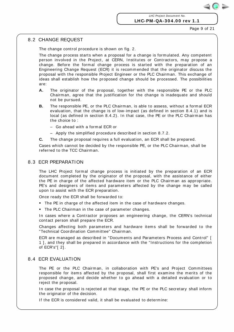
8.2 CHANGE REQUEST
The change control procedure is shown on fig. 2.
The change process starts when a proposal for a change is formulated. Any competentperson involved in the Project, at CERN, Institutes or Contractors, may propose achange. Before the formal change process is started with the preparation of anEngineering Change Request (ECR) it is recommended that the originator discuss theproposal with the responsible Project Engineer or the PLC Chairman. This exchange ofideas shall establish how the proposed change should be processed. The possibilitiesare:
A. The originator of the proposal, together with the responsible PE or the PLCChairman, agree that the justification for the change is inadequate and shouldnot be pursued.
B. The responsible PE, or the PLC Chairman, is able to assess, without a formal ECRevaluation, that the change is of low-impact (as defined in section 8.4.1) and islocal (as defined in section 8.4.2). In that case, the PE or the PLC Chairman hasthe choice to :
– Go ahead with a formal ECR or
– Apply the simplified procedure described in section 8.7.2.
C. The change proposal requires a full evaluation, an ECR shall be prepared.
Cases which cannot be decided by the responsible PE, or the PLC Chairman, shall bereferred to the TCC Chairman.
8.3 ECR PREPARATION
The LHC Project formal change process is initiated by the preparation of an ECRdocument completed by the originator of the proposal, with the assistance of eitherthe PE in charge of the affected hardware item or the PLC Chairman as appropriate.PE's and designers of items and parameters affected by the change may be calledupon to assist with the ECR preparation.
Once ready the ECR shall be forwarded to:
! The PE in charge of the affected item in the case of hardware changes.
! The PLC Chairman in the case of parameter changes.
In cases where a Contractor proposes an engineering change, the CERN's technicalcontact person shall prepare the ECR.
Changes affecting both parameters and hardware items shall be forwarded to the"Technical Coordination Committee" Chairman.
ECR are managed as described in "Documents and Parameters Process and Control" [1 ], and they shall be prepared in accordance with the "Instructions for the completionof ECR's"[ 2].
8.4 ECR EVALUATION
The PE or the PLC Chairman, in collaboration with PE's and Project Committeesresponsible for items affected by the proposal, shall first examine the merits of theproposed change, and decide whether to go ahead with a detailed evaluation or toreject the proposal.
In case the proposal is rejected at that stage, the PE or the PLC secretary shall informthe originator of the decision.
If the ECR is considered valid, it shall be evaluated to determine:
LHC Project Document No.
LHC-PM-QA-304.00 rev 1.1
Page 10 of 21
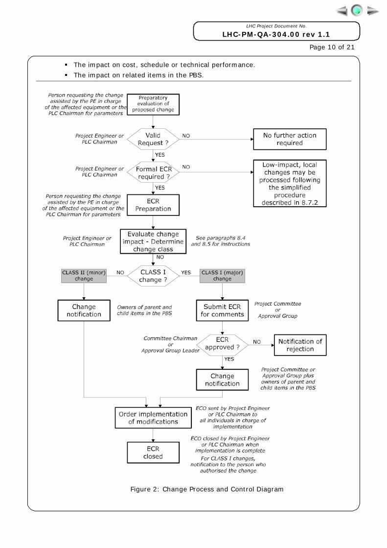
! The impact on cost, schedule or technical performance.
! The impact on related items in the PBS.
Figure 2: Change Process and Control Diagram
LHC Project Document No.
LHC-PM-QA-304.00 rev 1.1
Page 11 of 21
8.4.1 IMPACT ON COST, SCHEDULE AND TECHNICAL PERFORMANCE
For the purpose of change control, impact on cost, schedule and technicalperformance shall be classified as low impact or high impact based on the criteriagiven in table 1.
Cost Schedule Performance
Low impact Change of less thanCHF 200'000.-
Less than 1 monthdeviation on LHCcompletion target
date
Less than 5%deviation from
functionalrequirements
High impact Change ofCHF 200'000.- or
more
1 month or moredeviation on LHCcompletion target
date
5% or more deviationfrom functionalrequirements
Table 1: Definition of Impact on Cost, Schedule and Performance
When using table 1 the impact on cost, schedule and performance shall be comparedindividually to each of the criteria. It is sufficient that one of the high impact criteriabe met to determine that the change is high impact.
Ii may be difficult for a PE to evaluate all the implications of a change. If this is thecase the PE may seek the assistance of his supervisor and of Project Committees incarrying out the impact assessment.
8.4.2 IMPACT ON RELATED ITEMS
The second step of the evaluation shall establish whether the change's impact isextended or local.
Extended changes are changes affecting:
! LHC systems parameters.
! Principal items and their parent items in the LHC PBS.
! Identical child items of principal item attached to two or more principal items.
Local changes are changes affecting:
! one or more child items of a single principal item.
An extract of the PBS is shown in fig. 3 with examples of principal and child items.
Figure 3: Principal and Child Items in the PBS
LHC Project Document No.
LHC-PM-QA-304.00 rev 1.1
Page 12 of 21
When evaluating the extent of a change the interchangeability of the affected itemsshall be evaluated as well.
Interchangeability is defined as follows:
! Two or more parts or assemblies are considered interchangeable if, in allapplications, they are:
! Of an acceptable form and appearance to fulfil all requirements defined inthe specification.
! Of a proper fit (physical dimensions) to assemble with other mating items.
! Of a proper function to meet the item specification.
Parts and assemblies meeting these criteria are completely interchangeable,one for the other (both ways) with no special adjustments, modifications, oralterations to themselves or to related parts and assemblies.
The reference to all applications means that when a part or a assembly isused in more then one parent assembly the evaluation of interchangeabilitymust be done for each different assembly.
When evaluating the interchangeability of the children of a principal item the analysismust be done recurrently for all the children up to the principal item until it is foundthat the item is interchangeable.
If the analysis shows that the principal item becomes non-interchangeable as a resultof the change, the change becomes an extended change.
The process of interchangeability analysis is shown on fig. 4.
Figure 4: Interchangeability Evaluation Diagram
LHC Project Document No.
LHC-PM-QA-304.00 rev 1.1
Page 13 of 21
8.5 CLASSIFICATION OF CHANGES
The use of classes makes it possible to adapt the change process to the evaluatedimpact of changes and to minimize the effort required to process the change.
Two classes of changes are defined as follows:
CLASS I Major change-Non-interchangeable hardware modifications andchanges with a significant impact on cost, schedule or technicalperformance.
CLASS II Minor change-Interchangeable hardware modifications and changeswith a low impact on cost, schedule or technical performance.
Based on the evaluation of the impact of a change and its extent, the change class canbe determined the definitions in table2.
Local change Extended change
Low impact change CLASS II CLASS I
High impact change CLASS I CLASS I
Table 2: Change class definition
8.6 PROCESSING CLASS I CHANGES
Once the evaluation is complete the PE shall update the ECR with:
! The impact, extent and resulting CLASS of the change.
! His recommendation on the acceptance or refusal of the change.
! The list of actions necessary to implement the change.
! His name and the date of the recommendation.
The ECR shall then be forwarded to the appropriate Committee Chairman and/orApproval Group Leader. The Committee Chairman and/or Approval Group Leader shallthen forward the ECR to Committee members and/or Approval Group members with arequest for comments.
At the end of the time allocated for the submission of comments the CommitteeChairman and/or Approval Group Leader shall review the comments ant take the finaldecision of approval or rejection of the ECR. He shall then update the ECR with:
! The final decision of acceptance or refusal of the change.
! His name and the date of the decision.
The completed ECR is used as an ECN to inform all the involved individuals of theapproved change. The involved persons are:
! The members of the Committee and/or the members of the Approval Group.
! The PE in charge of the parent and child items of the affected item in the PBS.
! The PE's design team members.
The completed ECR is also forwarded as an ECO to all individuals in charge of theimplementation of the change.
8.7 PROCESSING CLASS II CHANGES
8.7.1 NORMAL PROCEDURE
Once the evaluation is complete the PE shall update the ECR with:
LHC Project Document No.
LHC-PM-QA-304.00 rev 1.1
Page 14 of 21
! The impact, extent and resulting CLASS of the change.
! His decision on the acceptance or refusal of the change.
! The list of actions necessary to implement the change.
! His name and the date of the decision.
The completed ECR is used as an ECN to inform all the involved individuals of theapproved change. The involved persons are:
! The PE in charge of the parent and child items of the changed item in the PBS.
! The PE's design team members.
The completed ECR is also forwarded as an ECO to all individuals in charge of theimplementation of the change.
8.7.2 SIMPLIFIED PROCEDURE
The simplified procedure may be applied only for low-impact changes that arelocalised to a single item of the PBS, with no effect whatever to other PBS items. Toensure the traceability of change following this procedure, particular care shall betaken to accurately describe the change in modified drawings and documents.
The PE responsible for the item shall:
! Instruct the design office to make the necessary modifications to CAD models anddrawings. The precise nature of the modification shall be entered in each drawing'smodification list.
! Instruct authors of documents, in particular engineering specifications, to make thenecessary changes. The precise nature of the modification shall be entered in eachdocument's change history.
! Submit the drawings and documents to the appropriate review and approvalprocess.
! Notify the PE responsible for the parent item in the PBS.
8.8 NOTIFICATION OF CLASS I CHANGE COMPLETION
When all the necessary actions to implement a CLASS I ECO are completed the PE incharge of the implementation shall:
! Update the ECO with his name and the date of the completion.
! Notify the person who authorised the change of the completion.
9. RELATED DOCUMENTATION
[ 1 ] LHC-PM-QA-303.00 Documents and Parameters Process and Control
[ 2 ] LHC-PM-QA-608.00 Instructions for the completion of ECR's
10. ANNEXES
A.1 ECR document cover page.
A.2 Extract of the LHC Project Breakdown Structure.(For the current up-to-date version of the PBS seehttp://edms.cern.ch/TWDM/cgi/twdmproto.pm?project=LHC&action=start) .
Large Hadron Collider Lyn EVANS 1 Infrastructure & General Machine Services Paul FAUGERAS
1.1 Civil Engineering Infrastructure J.-Luc BALDY LK 1.2 Electrical Distribution Network Gunnar FERNQVIST
1.2.1 AC Mains Network John PEDERSEN E,EH,EM 1.2.2 DC Network Schematics Paul PROUDLOCK D
1.3 Control & Data Network Robin LAUCKNER 1.4 Fluid Networks Mats WILHELMSSON
1.4.1 Air Ventilation Jean ROCHE FA 1.4.2 Water Cooling Bernard PIROLLET FW,FP,PR
1.5 Ring Cryogenic System Philippe LEBRUN Q 1.6 Tunnel Transportation Equipt & Infrastructure Keith KERSHAW LJ 1.7 Survey Equipt Jean-Pierre QUESNEL G
2 Arc & Dispersion Suppressor Equipt & Facilities Paul FAUGERAS 2.1 Cryo Distribution Line Wolfgang ERDT QRL
2.1.1 Supporting System Wolfgang ERDT HQRL 2.1.2 Standard Pipe Sections Wolfgang ERDT QRLP 2.1.3 Compensation Modules Wolfgang ERDT 2.1.4 Service Modules Wolfgang ERDT QRLS 2.1.5 QRL Jumpers Wolfgang ERDT 2.1.6 Return Box Wolfgang ERDT
2.2.1.1 Cold Mass Assembly Jos VLOGAERT LBM 2.2.1.1.1 Collared Coil Diego PERINI MB_A 2.2.1.1.2 Spool Pieces Albert IJSPEERT 2.2.1.1.3 Bus Bars Jean-Louis PERINET-MARQUET DC 2.2.1.1.4 Yoke & related Components Diego PERINI MB_A 2.2.1.1.5 Shrinking Cylinder & related Equipt Frederic SAVARY MB_S 2.2.1.1.6 Quench Diode Assembly Dietrich HAGEDORN DQD 2.2.1.1.7 Cold Bore Pipes & Insulation Frederic SAVARY VCCB 2.2.1.1.8 Beam Screens Oswald GROBNER VCSB 2.2.1.1.9 Heat Exchanger Tube Laurent Jean TAVIAN 2.2.1.1.10 Cold Mass Instrumentation Equipt Jos VLOGAERT
2.2.1.2 Dipole Cryostat & related Equipt Alain PONCET QBA 2.2.1.2.1 Vacuum Vessel Lloyd Ralph WILLIAMS QBA 2.2.1.2.2 Thermal Shield Lloyd Ralph WILLIAMS 2.2.1.2.3 Radiation Screen Lloyd Ralph WILLIAMS 2.2.1.2.4 Multi Layer Insulation Tore WIKBERG 2.2.1.2.5 Support Systems Vittorio PARMA QBH 2.2.1.2.6 Cryostat Instrumentation & Capillaries Lloyd Ralph WILLIAMS 2.2.1.2.7 Vacuum Tank Support System Lloyd Ralph WILLIAMS 2.2.1.2.8 Survey Reference Sockets Jean-Pierre QUESNEL 2.2.1.2.9 Fastening Devices for Transportation Lloyd Ralph WILLIAMS
2.2.2 Standard Arc Short Straight Sections Jean-Pierre GOURBER LQA 2.2.2.1 SSS Cold Mass Assembly Theodor Tortschanoff LQM
2.2.2.1.2 Inertia Tube & Flange Assembly Jean-Michel RIFFLET 2.2.2.1.3 Combined Sextupole-Dipole Magnet Albert IJSPEERT MSCB 2.2.2.1.4 Octupole Corrector Albert IJSPEERT MO 2.2.2.1.5 Tuning Quadrupole Albert IJSPEERT MQT 2.2.2.1.6 Skew Quadrupole Albert IJSPEERT MQS 2.2.2.1.7 Mounting Devices for Correctors Michel GENET 2.2.2.1.8 Electrical Connections Jean-Michel RIFFLET 2.2.2.1.9 Bus Bars Jean-Louis PERINET-MARQUET DC 2.2.2.1.10 Quench Diode Assembly Jean-Michel RIFFLET DQD 2.2.2.1.11 Cold Bore Pipes & Insulation Frederic SAVARY VCCQ 2.2.2.1.12 Beam Screens Oswald GROBNER VCSQ 2.2.2.1.13 Heat Exchanger Tube Laurent Jean TAVIAN 2.2.2.1.14 Cold Mass Instrumentation Equipt Theodor Tortschanoff
2.2.2.2 SSS Cryostat & related Equipt Peter ROHMIG QQA 2.2.2.2.1 SSS Vacuum Vessel Assembly Daniel VINCENT QQA 2.2.2.2.2 Thermal Shield Daniel VINCENT
Annex A2 Extract of the LHC ProjectBreakdown Structure (page 1)
LHC Project Document No.
LHC-PM-QA-304.00 rev 1.1
Page 17 of 21
2.2.2.2.3 Radiation Screen Daniel VINCENT 2.2.2.2.4 Multi Layer Insulation Tore WIKBERG 2.2.2.2.5 Support Systems Vittorio PARMA QQH 2.2.2.2.6 Cryostat Instrumentation & Capillaries Lloyd Ralph WILLIAMS 2.2.2.2.7 Vacuum Vessel Support System Peter ROHMIG 2.2.2.2.8 Survey Reference Sockets Jean-Pierre QUESNEL 2.2.2.2.9 Fastening Devices for Transportation Keith KERSHAW 2.2.2.2.10 Beam Loss Monitors Claude FISCHER
2.2.2.3 Technical Service Module Peter ROHMIG QQS 2.2.2.3.1 BPM & Beam Screen Assembly Peter ROHMIG 2.2.2.3.2 Cryogenic Components Wolfgang ERDT QQS 2.2.2.3.3 Insulation Vacuum Barrier System Vittorio PARMA QQV 2.2.2.3.4 Dipole Corrector Current Feedthrough Assembly Peter ROHMIG DFL 2.2.2.3.5 Cold Mass Instrumentation Feedthrough Peter ROHMIG 2.2.2.3.6 TSM Vacuum Vessel Assembly Peter ROHMIG QQS 2.2.2.3.7 Thermal Shield Peter ROHMIG 2.2.2.3.8 QQS Instrumentation Peter ROHMIG
2.2.3 Dispersion Suppressor Short Straight Sections Jean-Pierre GOURBER 2.3 other Arc Cryostats Components Alain PONCET
2.3.1 Interconnects Jean-Claude BRUNET LI 2.3.2 Auxilliary Bus Bars Knud DAHLERUP-PETERSEN DCC 2.3.3 other Vacuum Equipt Pierre STRUBIN
2.4 Powering Equipt Gunnar FERNQVIST RB ,RQF,RQD 2.4.1 Feed & Return Boxes Roberto SABAN DFB,DRB 2.4.2 Power Converters Frederick BORDRY RB ,RQF,RQD 2.4.3 Quench Protection System Felix RODRIGUEZ-MATEO DQ
2.5 Electronics & Control Equipment in Tunnel Robin LAUCKNER 2.5.1 Beam Instrumentation Electronics Claude FISCHER 2.5.2 Beam Loss Monitors Claude FISCHER 2.5.3 Vacuum Controls Pierre STRUBIN 2.5.4 Radiation Monitors Graham Roger STEVENSON
3 Insertion Region Equipt & Facilities at Points 1 & 5 Paul FAUGERAS 3.1 Infrastructure & General Services Paul FAUGERAS
3.1.1 Civil Engineering Infrastructure J.-Luc BALDY 3.1.1.1 CE Infrastructure at Point 1 Hubert RAMMER 3.1.1.2 CE Infrastructure at Point 5 Timothy WATSON
3.1.2 AC Electrical Distribution Network John PEDERSEN E,EH,EM 3.1.3 Control & Data Network Robin LAUCKNER 3.1.4 Fluid Networks Mats WILHELMSSON
3.1.4.1 Air Ventilation Jean ROCHE FA 3.1.4.2 Water Cooling Bernard PIROLLET FW
3.2 Cryo Distribution Line Wolfgang ERDT QRL 3.3 Insertion Magnets Thomas TAYLOR
3.3.3 Separation Magnets Thomas TAYLOR 3.3.3.1 Warm D1 Magnet Modules Thomas TAYLOR MBXW 3.3.3.2 SuperConducting D2 Magnet Thomas TAYLOR MBR
3.3.4 Corrector Magnets Albert IJSPEERT MCBX 3.4 Collimators Thomas TAYLOR TAN 3.5 Powering Equipt Gunnar FERNQVIST
3.5.1 Power Converters Frederick BORDRY 3.5.2 Copper Leads John PEDERSEN DW 3.5.3 HTS Current Leads Thomas TAYLOR DFL
3.6 other Vacuum Equipt Pierre STRUBIN 3.7 Beam Instrumentation Claude FISCHER 3.8 ATLAS Experiment PBS (Point1) Gerard BACHY 3.9 CMS Experiment PBS (Point 5) Thomas MEYER
4 Insertion Region Equipt & Facilities at Points 2 & 8 Paul FAUGERAS 4.1 Infrastructure & General Services Paul FAUGERAS
4.1.1 Civil Engineering Infrastructure J.-Luc BALDY 4.1.2 AC Electrical Distribution Network John PEDERSEN E,EH,EM
Annex A2 Extract of the LHC ProjectBreakdown Structure (page 2)
LHC Project Document No.
LHC-PM-QA-304.00 rev 1.1
Page 18 of 21
4.1.3 Control & Data Network Robin LAUCKNER 4.1.4 Fluid Networks Mats WILHELMSSON
4.1.4.1 Air Ventilation Jean ROCHE FA 4.1.4.2 Water Cooling Bernard PIROLLET FW
4.2 Cryo Distribution System Philippe LEBRUN 4.2.1 Surface Cryogenic Plant Udo WAGNER QSC,QSR 4.2.2 Cold Compressor Boxes Laurent Jean TAVIAN QUR,QURC 4.2.3 Interconnecting Box Laurent Jean TAVIAN QUI 4.2.4 Cryogenic Distribution Line Wolfgang ERDT QRL
4.3 Insertion Magnets Thomas TAYLOR 4.3.1 Inner Triplet Ranko OSTOJIC
4.3.1.1 SuperConducting Quadrupole Modules Ranko OSTOJIC MQX 4.3.1.2 Common Cryostats Ranko OSTOJIC QQX 4.3.1.3 Specific Feed Boxes Ranko OSTOJIC
4.7.1 Power Converters Frederick BORDRY 4.7.2 Copper Leads John PEDERSEN DW 4.7.3 HTS Current Leads Thomas TAYLOR DFL
4.8 other Vacuum Equipt Pierre STRUBIN 4.9 Beam Instrumentation Claude FISCHER
4.10. ALICE Experiment PBS (Point 2) Wolfgang KLEMPT 4.11 LHC-B Experiment PBS (Point 8) Hans Jurgen HILKE
5 Insertion Region Equipt & Facilities at Point 4 Paul FAUGERAS 5.1 Infrastructure & General Services Paul FAUGERAS
5.1.1 Civil Engineering Infrastructure J.-Luc BALDY 5.1.2 AC Electrical Distribution Network John PEDERSEN E,EH,EM 5.1.3 Control & Data Network Robin LAUCKNER 5.1.4 Fluid Networks Mats WILHELMSSON
5.1.4.1 Air Ventilation Jean ROCHE FA 5.1.4.2 Water Cooling Bernard PIROLLET FW
5.2 Cryo Plant & Cryo Distribution System Philippe LEBRUN 5.2.1 Surface Cryogenic Plant Udo WAGNER QSC,QSR 5.2.2 Cold Compressor Boxes Laurent Jean TAVIAN QUR,QURC 5.2.3 Interconnecting Box Laurent Jean TAVIAN QUI 5.2.4 Cryogenic Distribution Line Wolfgang ERDT QRL
5.3 Insertion Quadrupoles Thomas TAYLOR LQR 5.3.1 Quadrupole Cold Mass Thomas TAYLOR MQR 5.3.2 Isolated Cryostat Thomas TAYLOR QQR 5.3.3 Electrical Feed Box Thomas TAYLOR DFB
5.4 SuperConducting Separation Magnets Thomas TAYLOR MBR 5.5 Collimators Thomas TAYLOR 5.6 Powering Equipt Gunnar FERNQVIST
5.6.1 Power Converters Frederick BORDRY 5.6.2 Copper Leads John PEDERSEN DW 5.6.3 HTS Current Leads Thomas TAYLOR DFL
5.7 Radio Frequency Equipt Daniel BOUSSARD A 5.7.1 SuperConducting Cavities Volker RODEL ACS 5.7.2 Feedback Systems Trevor LINNECAR AD
5.7.2.1 Transverse Feedback Systems Trevor LINNECAR ADT 5.7.2.2 Longitudinal Feedback Systems Trevor LINNECAR ADL
5.7.3 Radio Frequency Power Plant Volker RODEL 5.7.4 Radio Frequency Instrum. & Control Equipt Volker RODEL ABD
5.8 other Vacuum Equipt Pierre STRUBIN 5.9 Beam Instrumentation Claude FISCHER
6 Insertion Region Equipt & Facilities at Points 3 & 7 Paul FAUGERAS 6.1 Infrastructure & General Services Paul FAUGERAS
Annex A2 Extract of the LHC Project Breakdown Structure (page 3)
LHC Project Document No.
LHC-PM-QA-304.00 rev 1.1
Page 19 of 21
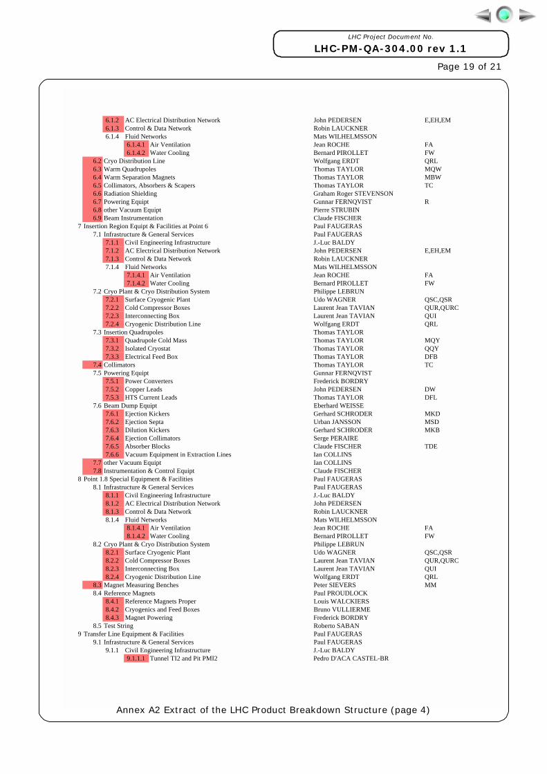
6.1.2 AC Electrical Distribution Network John PEDERSEN E,EH,EM 6.1.3 Control & Data Network Robin LAUCKNER 6.1.4 Fluid Networks Mats WILHELMSSON
6.1.4.1 Air Ventilation Jean ROCHE FA 6.1.4.2 Water Cooling Bernard PIROLLET FW
6.2 Cryo Distribution Line Wolfgang ERDT QRL 6.3 Warm Quadrupoles Thomas TAYLOR MQW 6.4 Warm Separation Magnets Thomas TAYLOR MBW 6.5 Collimators, Absorbers & Scapers Thomas TAYLOR TC 6.6 Radiation Shielding Graham Roger STEVENSON 6.7 Powering Equipt Gunnar FERNQVIST R 6.8 other Vacuum Equipt Pierre STRUBIN 6.9 Beam Instrumentation Claude FISCHER
7 Insertion Region Equipt & Facilities at Point 6 Paul FAUGERAS 7.1 Infrastructure & General Services Paul FAUGERAS
7.1.1 Civil Engineering Infrastructure J.-Luc BALDY 7.1.2 AC Electrical Distribution Network John PEDERSEN E,EH,EM 7.1.3 Control & Data Network Robin LAUCKNER 7.1.4 Fluid Networks Mats WILHELMSSON
7.1.4.1 Air Ventilation Jean ROCHE FA 7.1.4.2 Water Cooling Bernard PIROLLET FW
7.2 Cryo Plant & Cryo Distribution System Philippe LEBRUN 7.2.1 Surface Cryogenic Plant Udo WAGNER QSC,QSR 7.2.2 Cold Compressor Boxes Laurent Jean TAVIAN QUR,QURC 7.2.3 Interconnecting Box Laurent Jean TAVIAN QUI 7.2.4 Cryogenic Distribution Line Wolfgang ERDT QRL
7.3 Insertion Quadrupoles Thomas TAYLOR 7.3.1 Quadrupole Cold Mass Thomas TAYLOR MQY 7.3.2 Isolated Cryostat Thomas TAYLOR QQY 7.3.3 Electrical Feed Box Thomas TAYLOR DFB
7.4 Collimators Thomas TAYLOR TC 7.5 Powering Equipt Gunnar FERNQVIST
7.5.1 Power Converters Frederick BORDRY 7.5.2 Copper Leads John PEDERSEN DW 7.5.3 HTS Current Leads Thomas TAYLOR DFL
7.6 Beam Dump Equipt Eberhard WEISSE 7.6.1 Ejection Kickers Gerhard SCHRODER MKD 7.6.2 Ejection Septa Urban JANSSON MSD 7.6.3 Dilution Kickers Gerhard SCHRODER MKB 7.6.4 Ejection Collimators Serge PERAIRE 7.6.5 Absorber Blocks Claude FISCHER TDE 7.6.6 Vacuum Equipment in Extraction Lines Ian COLLINS
7.7 other Vacuum Equipt Ian COLLINS 7.8 Instrumentation & Control Equipt Claude FISCHER
8 Point 1.8 Special Equipment & Facilities Paul FAUGERAS 8.1 Infrastructure & General Services Paul FAUGERAS
8.1.1 Civil Engineering Infrastructure J.-Luc BALDY 8.1.2 AC Electrical Distribution Network John PEDERSEN 8.1.3 Control & Data Network Robin LAUCKNER 8.1.4 Fluid Networks Mats WILHELMSSON
8.1.4.1 Air Ventilation Jean ROCHE FA 8.1.4.2 Water Cooling Bernard PIROLLET FW
8.2 Cryo Plant & Cryo Distribution System Philippe LEBRUN 8.2.1 Surface Cryogenic Plant Udo WAGNER QSC,QSR 8.2.2 Cold Compressor Boxes Laurent Jean TAVIAN QUR,QURC 8.2.3 Interconnecting Box Laurent Jean TAVIAN QUI 8.2.4 Cryogenic Distribution Line Wolfgang ERDT QRL
8.3 Magnet Measuring Benches Peter SIEVERS MM 8.4 Reference Magnets Paul PROUDLOCK
8.4.1 Reference Magnets Proper Louis WALCKIERS 8.4.2 Cryogenics and Feed Boxes Bruno VULLIERME 8.4.3 Magnet Powering Frederick BORDRY
8.5 Test String Roberto SABAN 9 Transfer Line Equipment & Facilities Paul FAUGERAS
9.1 Infrastructure & General Services Paul FAUGERAS 9.1.1 Civil Engineering Infrastructure J.-Luc BALDY
9.1.1.1 Tunnel TI2 and Pit PMI2 Pedro D'ACA CASTEL-BR
Annex A2 Extract of the LHC Product Breakdown Structure (page 4)
LHC Project Document No.
LHC-PM-QA-304.00 rev 1.1
Page 20 of 21
9.1.1.2 Tunnel TI8 Luz Anastasia LOPEZ-HERNANDEZ 9.1.2 AC Electrical Distribution Network John PEDERSEN 9.1.3 Control & Data Network Robin LAUCKNER 9.1.4 Fluid Networks Mats WILHELMSSON
9.1.4.1 Air Ventilation Jean ROCHE FA 9.1.4.2 Water Cooling Bernard PIROLLET FW


![DRAWING AND 3D MODEL MANAGEMENT AND …lhc-proj-qawg.web.cern.ch/lhc-proj-qawg/CD-ROM/Quality/QA305.pdf · Buildings and Civil Engineering Works" [ 9]. Drawing sequential numbers](https://static.documents.pub/doc/80x56/5aa4a01e7f8b9a1d728c1f4b/drawing-and-3d-model-management-and-lhc-proj-qawgwebcernchlhc-proj-qawgcd-romqualityqa305pdfbuildings.jpg)


