2
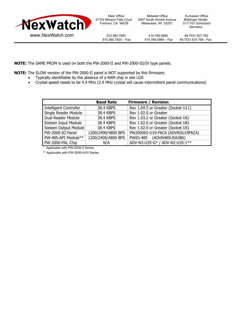
Main Office Midwest Office European Office 47102 Mission Falls Court 5007 South Howell Avenue Böblinger Straβe Fremont, CA 94539 Milwaukee, WI 53207 D-71101 Schönaich Germany www.NexWatch.com 510.360.7800 414.769.5980 49.7031.637.782 510.360.7820 – Fax 414.769.5989 – Fax 49.7031.637.769 - Fax Configuration Setting for using the PW-2000-IO with the PW-5000 Controller The PW-2000-IO firmware allows for existing PW-2000 series control panels to act as downstream devices on a PW-5000 Intelligent Controller. A UPGPW2K5KIO chipset will need to be ordered for every existing PW-2000 series controller on the PW-5000 line. PW-2000-II Controllers The PW-2000-II Series controller will have two separate boards that need to be modified with the chip change, the actual control panel and the PW-485-API module. 1. Remove primary and backup power from the controller. 2. Verify that the PAL chip inserted in socket U35 is the “Advanced” chip labeled ADV-N2-U35-1, if this chip is labeled STD-N2-U35-1 it will need to be replaced with the “Advanced” chip. 3. Remove the chip located in socket U19, this is the firmware PROM chip for the PW-2000-II controller. 4. Insert the new firmware PROM chip from the UPGPW2K5KIO set labeled PW2000IO-U19-F6CA (ADVN3U19F6CA) into the socket labeled U19. Make sure that the chip “notch” is correct and pointing in the direction matching the outline on the circuit board. 5. On the PW-485-API module, verify that power has been removed from the device before proceeding. 6. Remove the chip from socket U1 and insert the new 485 PROM chip from the UPGPW2K5KIO set labeled PWIO-485 (ADVN485U5A2B6). Make sure that the chip “notch” is correct and pointing in the direction matching the outline on the circuit board. 7. Check the user manual for controller and 485 baud rate dip switch setting and that they conform to the baud rates stated below. 8. Reapply power to the control panel, and the 485 module. PW-2000-III/IV Controllers The PW-2000-III/IV Series controller will have only one board that need to be modified with the chip change, the main circuit board contains both the panel PROM and the 485 PROM firmware. 1. Remove primary and backup power from the controller. 2. Verify that the PAL chip inserted in socket U35 is the “Advanced” chip labeled ADV-N3-U35-G, if this chip is labeled STD-N3-U35-1 it will need to be replaced with the “Advanced” chip. 3. Remove the chip located in socket U19, this is the firmware PROM chip for the PW-2000-II controller. 4. Insert the new firmware PROM chip from the UPGPW2K5KIO set labeled PW2000IO-U19-F6CA (ADVN3U19F6CA) into the socket labeled U19. Make sure that the chip “notch” is correct and pointing in the direction matching the outline on the circuit board. 5. Locate the 485 PROM chip located in socket U5. Remove the chip from socket U5 and insert the new 485 PROM chip from the UPGPW2K5KIO set labeled PWIO-485 (ADVN485U5A2B6). Make sure that the chip “notch” is correct and pointing in the direction matching the outline on the circuit board. 6. Check the user manual for controller baud rate dip switch setting and that it conforms to the baud rates stated below 7. Reapply power to the control panel.


![Basic Principle and Configuration Guide for ZXCTN Linear and PW Protection_R1[1].0](https://static.documents.pub/doc/80x56/577cc5821a28aba7119c9e09/basic-principle-and-configuration-guide-for-zxctn-linear-and-pw-protectionr110.jpg)


