CHAPTER 2-1 Cisco Content Services Switch Content Load-Balancing Configuration Guide OL-6710-01 2 Configuring Flow and Port Mapping Parameters This chapter describes how to configure flow and port mapping parameters for the CSS. Information in this chapter applies to all CSS models, except where noted. This chapter contains the following major sections: • Configuring Flow Parameters • Configuring Flow Inactivity Timeouts on Content Rules and Source Groups • Configuring Flow Processing for Fragmented IP Packets • Configuring a CSS to Send a TCP Reset if a VIP Is Unavailable • Configuring the Flow-State Table • Configuring CSS Port Mapping For information on how the CSS handles flows, see Chapter 1, Content Load-Balancing Overview. Configuring Flow Parameters To configure flow parameters for the CSS, use the flow command. The options for this global configuration mode command are as follows: • flow permanent - Creates permanent TCP or UDP ports that are not reclaimed • flow reserve-clean - Reclaims interval flows with port numbers less than or equal to 23
Transcript
Cisco Content Services Switch ConteOL-6710-01
C H A P T E R 2
Configuring Flow and Port Mapping Parameters
This chapter describes how to configure flow and port mapping parameters for the CSS. Information in this chapter applies to all CSS models, except where noted.
This chapter contains the following major sections:
• Configuring Flow Parameters
• Configuring Flow Inactivity Timeouts on Content Rules and Source Groups
• Configuring Flow Processing for Fragmented IP Packets
• Configuring a CSS to Send a TCP Reset if a VIP Is Unavailable
• Configuring the Flow-State Table
• Configuring CSS Port Mapping
For information on how the CSS handles flows, see Chapter 1, Content Load-Balancing Overview.
Configuring Flow ParametersTo configure flow parameters for the CSS, use the flow command. The options for this global configuration mode command are as follows:
• flow permanent - Creates permanent TCP or UDP ports that are not reclaimed
• flow reserve-clean - Reclaims interval flows with port numbers less than or equal to 23
2-1nt Load-Balancing Configuration Guide
Chapter 2 Configuring Flow and Port Mapping ParametersConfiguring Flow Parameters
• flow tcp-mss - Configures the TCP maximum segment size that the CSS expects to receive from the transmitting device
• flow statistics - Displays statistics on currently allocated flows
Note Flow parameter setup by the CSS is restricted on the following TCP or UDP ports: 67 (BOOTP server), 68 (BOOTP client), 137 (NETBIOS name service), 138 (NETBIOS datagram service), 161 (SNMP), 162 (SNMP traps), 520 (RIP), and 8089 (restricted UDP only).
This section includes the following topics:
• Configuring Permanent Connections for TCP or UDP Ports
• Configuring TCP Maximum Segment Size
• Reclaiming Reserved Telnet and FTP Control Ports
• Showing Flow Statistics
Configuring Permanent Connections for TCP or UDP PortsThe CSS allows you to configure a maximum of 20 TCP or UDP ports that have permanent connections and will not be reclaimed by the CSS when the flows are inactive. Use the flow permanent port1 portnumber (through flow permanent port 20 portnumber) commands to configure a TCP or UDP port as a permanent connection. Enter a port number from 0 to 65535. The default is 0.
A CSS may reclaim flows that have not received an ACK or content request after approximately 15 seconds. To prevent the CSS from reclaiming flows to a specific source or destination port, specify one of the flow permanent port commands and identify the TCP or UDP port number you do not want reclaimed.
For example, to configure port 80 as a permanent connection, enter:
Chapter 2 Configuring Flow and Port Mapping ParametersConfiguring Flow Parameters
We recommend that when you configure a flow permanent port command you also enable the cmd-sched command to periodically remove the permanent port and allow for cleanup. For details on using the cmd-sched command to configure the scheduled execution of any CLI command, refer to the Cisco Content Services Switch Administration Guide.
Configuring TCP Maximum Segment SizeThe maximum segment size (MSS) is the largest amount of TCP data that can be transmitted in one segment. The need for a smaller MSS between devices may be necessary in rare instances due to network restrictions between devices. Use the flow tcp-mss command to configure the TCP MSS that the CSS expects to receive from the transmitting device. The flow tcp-mss command changes the MSS value in the TCP header OPTIONS field of a SYN segment, to reduce the MSS from the default value of 1460 bytes.
The flow tcp-mss command applies only when the client is accessing a Layer 5 content rule. The CSS does not negotiate TCP maximum segment size for Layer 3 or Layer 4 content rules.
Enter a maximum segment size (in bytes) from 1 to 1460. The default is 1460 bytes. Use the no form of the command to reset the TCP maximum segment size back to the default value of 1460 bytes.
Caution Do not define a smaller than necessary TCP maximum segment size with the flow tcp-mss command. Smaller payloads may be less efficient due to increased overhead.
To configure a TCP maximum segment size of 1400 bytes, enter:
(config)# flow tcp-mss 1400
To reset the TCP maximum segment size to the default value of 1460 bytes, enter:
Chapter 2 Configuring Flow and Port Mapping ParametersConfiguring Flow Parameters
Reclaiming Reserved Telnet and FTP Control PortsControl ports have port numbers less than or equal to 23. When the CSS determines that one of these ports has a flow with asymmetrical routing, it reclaims the port.
Use the flow reserve-clean command to define how often the CSS scans flows from reserved Telnet and FTP control ports to reclaim them. Enter the flow reserve-clean time, in seconds, as the interval the CSS uses to scan flows. Enter an integer from 0 to 100. The default is 10. To disable the port reclaiming process, enter a flow reserve-clean value of 0.
For example, to specify an interval of 36 seconds:
(config)# flow reserve-clean 36
To disable flow cleanup on Telnet and FTP control ports, enter:
(config)# no flow reserve-clean
Showing Flow StatisticsUse the flow statistics command to display statistics on active flows or Flow Control Blocks (FCBs) on the CSS interfaces.
Note To display summary information about redundant dormant flows, use the flow statistics dormant command. Refer to the Cisco Content Services Switch Redundancy Configuration Guide for details.
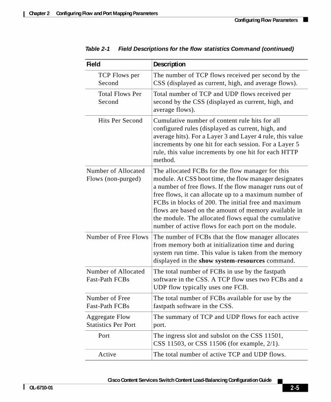
Table 2-1 describes the fields in the flow statistics output.
Table 2-1 Field Descriptions for the flow statistics Command
Field Description
Flow Manager Statistics - Slot n, Subslot n
Flow manager statistics for the module in the specified slot and subslot in the CSS chassis. The flow manager is responsible for FCB creation and flow mapping.
UDP Flows per Second
The number of UDP flows received per second by the CSS (displayed as current, high, and average flows).
Chapter 2 Configuring Flow and Port Mapping ParametersConfiguring Flow Parameters
TCP Flows per Second
The number of TCP flows received per second by the CSS (displayed as current, high, and average flows).
Total Flows Per Second
Total number of TCP and UDP flows received per second by the CSS (displayed as current, high, and average flows).
Hits Per Second Cumulative number of content rule hits for all configured rules (displayed as current, high, and average hits). For a Layer 3 and Layer 4 rule, this value increments by one hit for each session. For a Layer 5 rule, this value increments by one hit for each HTTP method.
Number of Allocated Flows (non-purged)
The allocated FCBs for the flow manager for this module. At CSS boot time, the flow manager designates a number of free flows. If the flow manager runs out of free flows, it can allocate up to a maximum number of FCBs in blocks of 200. The initial free and maximum flows are based on the amount of memory available in the module. The allocated flows equal the cumulative number of active flows for each port on the module.
Number of Free Flows The number of FCBs that the flow manager allocates from memory both at initialization time and during system run time. This value is taken from the memory displayed in the show system-resources command.
Number of Allocated Fast-Path FCBs
The total number of FCBs in use by the fastpath software in the CSS. A TCP flow uses two FCBs and a UDP flow typically uses one FCB.
Number of Free Fast-Path FCBs
The total number of FCBs available for use by the fastpath software in the CSS.
Aggregate Flow Statistics Per Port
The summary of TCP and UDP flows for each active port.
Port The ingress slot and subslot on the CSS 11501, CSS 11503, or CSS 11506 (for example, 2/1).
Active The total number of active TCP and UDP flows.
Table 2-1 Field Descriptions for the flow statistics Command (continued)
Chapter 2 Configuring Flow and Port Mapping ParametersConfiguring Flow Inactivity Timeouts on Content Rules and Source Groups
Configuring Flow Inactivity Timeouts on Content Rules and Source Groups
Use this feature with a CSS to configure flow inactivity timeout values for TCP and UDP flows on a per content rule and per source group basis. This timeout value is not the frequency with which a CSS reclaims flow resources, but is the time period that must elapse for an idle flow before the CSS marks the flow for cleanup.
Timeout Value PrecedenceThe CSS uses the following guidelines in the order presented when reclaiming flow resources:
1. If a flow matches on a content rule, the CSS checks for a user-configured timeout value and uses that timeout value if one exists.
2. If the flow matches on a source group, the CSS checks for a user-configured timeout value and uses that timeout value if one exists.
3. If you have configured a permanent port using the flow permanent port command (see the “Configuring Permanent Connections for TCP or UDP Ports” section), the CSS sets the flow timeout value to 0, which means that the flow should never time out.
4. If none of the above conditions are met, then the CSS uses the default timeout value for the protocol type. For more information, see the “Displaying Flow Timeout Statistics” section.
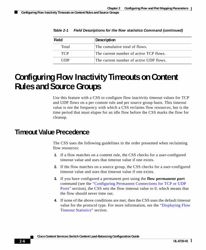
Total The cumulative total of flows.
TCP The current number of active TCP flows.
UDP The current number of active UDP flows.
Table 2-1 Field Descriptions for the flow statistics Command (continued)
Chapter 2 Configuring Flow and Port Mapping ParametersConfiguring Flow Inactivity Timeouts on Content Rules and Source Groups
Configuring Flow TimeoutsTo specify the number of seconds for which an idle flow can exist before the CSS tears it down, use the flow-timeout-multiplier command. Specify this command in owner-content or group configuration mode. The syntax for this command is:
flow-timeout-multiplier number
Note If you configure a source group with destination services for client source NATing, you need to configure the flow-timeout multiplier command only on the content rule. The CSS sets the same flow timeout value for flows in both directions. If you configure different timeout values on the content rule and on the source group, the CSS uses the timeout value configured on the content rule for both flows.
Enter an integer for the number variable from 0 to 65534. The CSS multiplies the value you specify by 16 to calculate the flow timeout in seconds. The default value depends on the TCP or UDP port number (see the “Displaying Flow Timeout Statistics” section). This default value applies only to flows that you create under a content rule or source group.
A value of zero (no timeout) instructs the CSS to never tear down the flow, resulting in a permanent flow and lost resources. Specifying a value of zero is equivalent to entering the flow permanent port command (see the “Configuring Permanent Connections for TCP or UDP Ports” section).
Note We do not recommend that you set the flow-timeout multiplier command to 0 for UDP flows on Layer 3 and Layer 4 content rules. If the value is set to 0, the CSS does not clean up the resources for the UDP flows.
Note The CSS tears down the FTP control channel after 10 minutes of idle time. This teardown may occur during a file transfer if the transfer exceeds 10 minutes. Use the flow-timeout-multiplier command on the associated content rule to configure the timeout to a value that can accommodate the expected duration of the FTP file transfers.
To disable the configured flow-timeout-multiplier value and restore the default timeout for the port type, enter:
(config-owner-content[cisco-rule1])# no flow-timeout(config-group[group1])# no flow-timeout
Displaying Flow Timeout StatisticsUse the show flow-timeout default command to display the default timeout values for TCP and UDP ports and applications. The default values are not user configurable. Table 2-2 shows the fields in the show flow-timeout default command output.
Use the show flow-timeout configured command to display the configured flow timeout values. The command output includes the content rule or source group for which you configured the flow timeout value.
Table 2-3 describes the fields in the show flow-timeout configured command output.
Table 2-2 Field Descriptions for show flow-timeout default Command
Field Description
TCP/IP Port Default TCP or UDP port numbers.
Application Names of the default TCP or UDP applications.
Inactivity Timeout Seconds
Default flow inactivity timeouts, in seconds, for the TCP or UDP port. If a flow is idle for the amount of time specified in the timeout value, the CSS tears down the flow and reclaims the flow resources.
Chapter 2 Configuring Flow and Port Mapping ParametersConfiguring Flow Processing for Fragmented IP Packets
Displaying Content Rule and Source Group InformationIf you configure a flow timeout value in a content rule or a source group, the show rule or show group command output includes an additional field called Flow Timeout Multiplier. This field contains the configured timeout value assigned to flows that match on the rule or group.
Configuring Flow Processing for Fragmented IP Packets
By default, a CSS does not process fragmented TCP and UDP IP packets (IP fragments) in the flow path, but simply routes them according to standard IP routing practices. As a result, IP fragments do not match on configuration items such as content rules and source groups and, therefore, the CSS does not NAT or load balance the fragments.
When you enable flow processing for IP fragments, a CSS processes the IP fragments in the flow path using the IP address and TCP port or UDP port information in the IP header and in the TCP or UDP header. The CSS then forwards and NATs the individual fragments of a packet based on the configured content rules and source groups matched by the fragments.
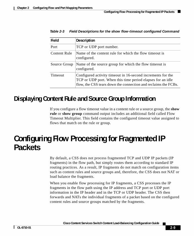
Table 2-3 Field Descriptions for the show flow-timeout configured Command
Field Description
Port TCP or UDP port number.
Content Rule Name of the content rule for which the flow timeout is configured.
Source Group Name of the source group for which the flow timeout is configured.
Timeout Configured activity timeout in 16-second increments for the TCP or UDP port. When this time period elapses for an idle flow, the CSS tears down the connection and reclaims the FCBs.
Chapter 2 Configuring Flow and Port Mapping ParametersConfiguring Flow Processing for Fragmented IP Packets
This feature supports only Layer 3 and Layer 4 content rules. For Layer 5 content rules, use the flow tcp-mss command. For details about the flow-tcp-mss command, see the “Configuring Flow Parameters” section.
Use this feature to support:
• Microsoft Media Server using Microsoft Media Server UDP (MMSU) protocol and other applications that fragment UDP IP packets
• E-mail or other applications that fragment TCP IP packets
• Applications and devices that do not support MTU path discovery
• Network configurations where TCP and UDP IP packets must be fragmented to traverse the network
Note Whenever possible, avoid applications or network configurations that create IP fragments. This feature provides support for those edge conditions where IP fragmentation is unavoidable.
This section describes how to configure flow processing for fragmented IP packets. It includes the following topics:
• What Is IP Packet Fragmentation?
• Enabling Flow Processing for Fragmented IP Packets
• Configuring the Maximum Assembled Size
• Configuring the Minimum Fragment Size
• Resetting IP Fragment Statistics
• Displaying IP Fragment Statistics
What Is IP Packet Fragmentation?An IP fragment is a part of a larger complete IP packet. IP packets require fragmentation when the next-hop network’s maximum transmit unit (MTU) is less than the incoming packet size. The transmitting device divides the packet into smaller pieces that the network medium can accommodate and copies the packet IP header into each fragment. Packets can be fragmented by the source host, intermediate routers, and other network devices.
Chapter 2 Configuring Flow and Port Mapping ParametersConfiguring Flow Processing for Fragmented IP Packets
IP packet fragmentation is generally considered an undesirable condition because fragmentation and subsequent reassembly of packets cause additional CPU and network overhead. However, despite the best efforts of network designers, some fragmentation is inevitable because of the different network media with varying MTUs that support the IP protocol.
For more information about IP packet fragmentation, refer to RFC 791 and RFC 815.
Configuration RestrictionsThe following TCP applications are not supported when a CSS receives fragmented packets and flow processing for TCP IP fragments is enabled:
• Layer 5 content rules when a client request is fragmented. There is no fall back to a Layer 4 or Layer 3 rule if configured.
• HTTPS client (SSL) with an SSL module for front-end SSL termination.
• HTTPS client (SSL) without an SSL module, with the advanced-balance-ssl command configured.
• FTP control channel.
• ArrowPoint cookies.
Note The CSS cannot inspect the UDP/TCP payload of a fragmented IP packet to make a load-balancing decision.
Enabling Flow Processing for Fragmented IP PacketsTo allow a CSS to flow-process IP fragments, use the udp-ip-fragment-enabled or the tcp-ip-fragment-enabled command in global configuration mode. By default, this feature is disabled.
Note The ip-fragment-enabled command has been deprecated (obsoleted). The CSS automatically converts the ip-fragment-enabled command to the udp-ip-fragment-enabled command.
Chapter 2 Configuring Flow and Port Mapping ParametersConfiguring Flow Processing for Fragmented IP Packets
To reset the default behavior of the CSS to forward IP fragments, use the no form of the command.
For example, enter:
(config)# no udp-ip-fragment-enabled(config)# no tcp-ip-fragment-enabled
Note This feature performs content rule-based forwarding using Layer 3 (IP address) and Layer 4 (TCP or UDP port) information in the IP header and the TCP or UDP header. Layer 5 forwarding decisions for IP fragments, based on the packet payload (data), are not supported.
Configuring the Maximum Assembled SizeThe maximum assembled size is the total length of an IP packet if all the IP fragments were assembled into the original packet. Assembled IP packets should be no larger than 64 KB. As the CSS receives the IP fragments, it checks the fragments against the maximum assembled size value. If a fragment IP offset plus the IP payload (data) length is greater than the configured maximum assembled size, the CSS increments the Max Assembled Size error field in the show ip-fragment-stats command output and discards the packet. See the “Displaying IP Fragment Statistics” section.
Note To eliminate unnecessary processing overhead, the CSS does not reassemble fragmented IP packets.
To specify the maximum assembled size for TCP and UDP IP fragments, use the ip-fragment max-assembled-size command. The syntax of this global configuration mode command is:
ip-fragment max-assembled-size number
The number variable specifies the maximum size of an assembled packet in bytes. Enter an integer from 2048 to 65535. The default is 5120 bytes.
Chapter 2 Configuring Flow and Port Mapping ParametersConfiguring Flow Processing for Fragmented IP Packets
To restore the default maximum IP fragment assembled size to 5120 bytes, use the no form of the command.
For example, enter:
(config)# no ip-fragment max-assembled-size
Configuring the Minimum Fragment SizeThe minimum fragment size is the smallest IP payload in an IP fragment that a CSS accepts. As the CSS receives the IP fragments, it checks the fragments against the minimum fragment size value. If a fragment IP payload length is less than the configured minimum fragment size, the CSS increments the Less Than Min Size error field in the show ip-fragment-stats command output and discards the packet. See the “Displaying IP Fragment Statistics” section.
To specify the smallest IP fragment payload for TCP and UDP IP fragments based on your applications, use the ip-fragment min-fragment-size command. This command also provides protection against fragment attacks, which can consist of a chain of valid-looking, but very small, fragments.
The syntax of this global configuration mode command is:
ip-fragment min-fragment-size number
The number variable specifies the size of the smallest IP fragment payload that the CSS supports in bytes. Enter an integer from 64 to 1024. The default is 1024 bytes.
For example, enter:
(config)# ip-fragment min-fragment-size 256
Note Requiring that the minimum fragment size be at least 64 bytes guarantees that the IP header and the TCP or UDP header information is present in the first fragment.
To restore the default minimum IP fragment payload size to 1024 bytes, use the no form of the command.
Chapter 2 Configuring Flow and Port Mapping ParametersConfiguring Flow Processing for Fragmented IP Packets
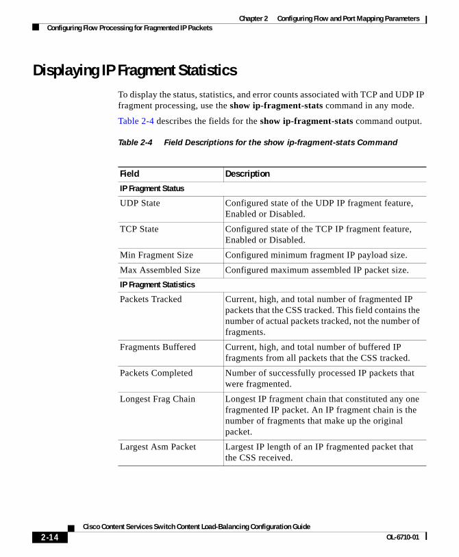
Displaying IP Fragment StatisticsTo display the status, statistics, and error counts associated with TCP and UDP IP fragment processing, use the show ip-fragment-stats command in any mode.
Table 2-4 describes the fields for the show ip-fragment-stats command output.
Table 2-4 Field Descriptions for the show ip-fragment-stats Command
Field Description
IP Fragment Status
UDP State Configured state of the UDP IP fragment feature, Enabled or Disabled.
TCP State Configured state of the TCP IP fragment feature, Enabled or Disabled.
Min Fragment Size Configured minimum fragment IP payload size.
Max Assembled Size Configured maximum assembled IP packet size.
IP Fragment Statistics
Packets Tracked Current, high, and total number of fragmented IP packets that the CSS tracked. This field contains the number of actual packets tracked, not the number of fragments.
Fragments Buffered Current, high, and total number of buffered IP fragments from all packets that the CSS tracked.
Packets Completed Number of successfully processed IP packets that were fragmented.
Longest Frag Chain Longest IP fragment chain that constituted any one fragmented IP packet. An IP fragment chain is the number of fragments that make up the original packet.
Largest Asm Packet Largest IP length of an IP fragmented packet that the CSS received.
Chapter 2 Configuring Flow and Port Mapping ParametersConfiguring Flow Processing for Fragmented IP Packets
Smallest Fragment Smallest fragment IP payload length that the CSS received. This field does not include the last fragment in any IP fragment because its payload can be any size.
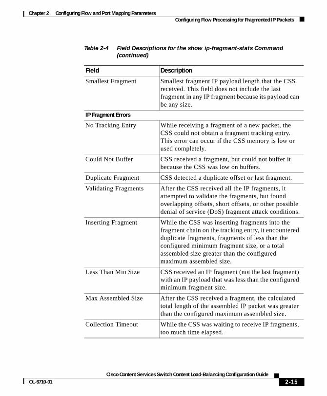
IP Fragment Errors
No Tracking Entry While receiving a fragment of a new packet, the CSS could not obtain a fragment tracking entry. This error can occur if the CSS memory is low or used completely.
Could Not Buffer CSS received a fragment, but could not buffer it because the CSS was low on buffers.
Duplicate Fragment CSS detected a duplicate offset or last fragment.
Validating Fragments After the CSS received all the IP fragments, it attempted to validate the fragments, but found overlapping offsets, short offsets, or other possible denial of service (DoS) fragment attack conditions.
Inserting Fragment While the CSS was inserting fragments into the fragment chain on the tracking entry, it encountered duplicate fragments, fragments of less than the configured minimum fragment size, or a total assembled size greater than the configured maximum assembled size.
Less Than Min Size CSS received an IP fragment (not the last fragment) with an IP payload that was less than the configured minimum fragment size.
Max Assembled Size After the CSS received a fragment, the calculated total length of the assembled IP packet was greater than the configured maximum assembled size.
Collection Timeout While the CSS was waiting to receive IP fragments, too much time elapsed.
Table 2-4 Field Descriptions for the show ip-fragment-stats Command
Chapter 2 Configuring Flow and Port Mapping ParametersConfiguring Flow Processing for Fragmented IP Packets
Resetting IP Fragment StatisticsTo reset the TCP and UDP IP fragment statistics, use the zero ip-fragment-stats command in any mode. This command resets the values of the statistics in the IP Fragment Statistics and IP Fragment Errors sections of the show ip-fragment-stats command output to zero.
For more information about the show ip-fragment-stats command, see the “Displaying IP Fragment Statistics” section.
Flow Timeout After the CSS received all fragments of an IP packet and a fragment was sent to flow processing, the entry timed out before the fragment returned.
IPv4 Header The CSS received a fragment with an invalid IPv4 header length compared with the total IP fragment size.
RxQueue Full The CSS flow-processing receive queue for IP fragments was full. The CSS discarded the IP fragments.
Table 2-4 Field Descriptions for the show ip-fragment-stats Command
Chapter 2 Configuring Flow and Port Mapping ParametersConfiguring a CSS to Send a TCP Reset if a VIP Is Unavailable
Configuring a CSS to Send a TCP Reset if a VIP Is Unavailable
If a Layer 3 or Layer 4 content rule VIP that a CSS is hosting is unavailable, the CSS, by default:
• Rejects a TCP packet sent to that VIP by a client
• Drops the TCP packet
This behavior can occur when a packet:
• Matches a Layer 3 or Layer 4 content rule that has no active services
• Matches a Layer 3 or Layer 4 content rule with services that have reached their maximum number of connections
If a CSS rejects a TCP packet, the client can retransmit the packet. If no services become available for a matching Layer 3 or Layer 4 content rule, the client application becomes unresponsive and either the connection or the application eventually times out. It takes the application a variable amount of time to time out. The latency caused by this time-out process is unacceptable for some applications.
This feature allows you to configure a CSS to send a TCP RST to the client in response to the TCP packet if the VIP is unavailable. If the application receives the TCP RST, the application stops retransmitting the packet and usually displays an error message about the failed connection attempt.
Note For Layer 5 spoofed connections, if the CSS rejects the content request, it always sends a TCP RST to the client. This behavior has not changed.
Applications where this feature may be useful include:
• Web browsers
• Telnet
• FTP
To configure a CSS to send a TCP RST to a client when a VIP is unavailable, use the flow tcp-reset-vip-unavailable command in global configuration mode. The CSS sends the TCP RST only in response to a TCP packet that is destined for a VIP that the CSS is hosting and only if that VIP is unavailable.
Chapter 2 Configuring Flow and Port Mapping ParametersConfiguring the Flow-State Table
For example, enter:
(config)# flow tcp-reset-vip-unavailable
To return the CSS behavior to the default of dropping the TCP packet if a VIP is unavailable, enter:
(config)# no flow tcp-reset-vip-unavailable
To display the number of TCP RSTs that a CSS sent because a VIP was unavailable, enter the show ip statistics command. For more information on the show ip statistics command, refer to the Cisco Content Services Switch Routing and Bridging Configuration Guide.
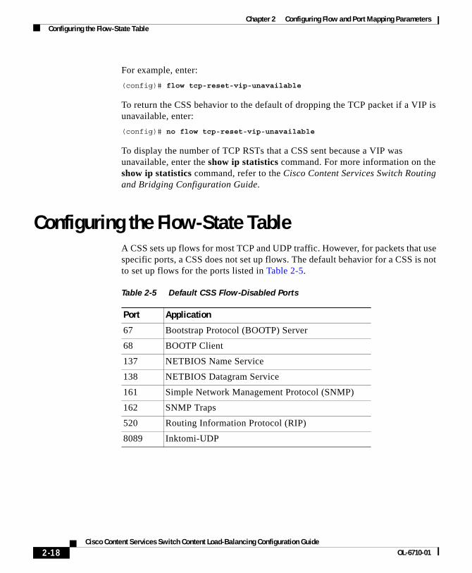
Configuring the Flow-State TableA CSS sets up flows for most TCP and UDP traffic. However, for packets that use specific ports, a CSS does not set up flows. The default behavior for a CSS is not to set up flows for the ports listed in Table 2-5.
Chapter 2 Configuring Flow and Port Mapping ParametersConfiguring the Flow-State Table
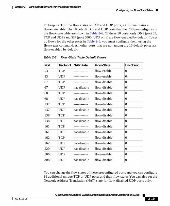
To keep track of the flow states of TCP and UDP ports, a CSS maintains a flow-state table. The 10 default TCP and UDP ports that the CSS preconfigures in the flow-state table are shown in Table 2-6. Of these 10 ports, only DNS (port 53, TCP and UDP) and SIP (port 5060, UDP only) are flow-enabled by default. To set up flows for the other ports in Table 2-6, you must configure them using the flow-state command. All other ports that are not among the 10 default ports are flow-enabled by default.
You can change the flow states of these preconfigured ports and you can configure 16 additional unique TCP or UDP ports and their flow states.You can also set the Network Address Translation (NAT) state for flow-disabled UDP ports only.
Chapter 2 Configuring Flow and Port Mapping ParametersConfiguring the Flow-State Table
If a CSS receives any traffic destined to its own IP address or VIP address and the port specified by that traffic is flow-disabled and NAT-disabled, the CSS sends an ICMP port unreachable message to the client.
When the CSS receives TCP packets on a flow-disabled port, it does not NAT those packets. In this case, the CSS simply forwards the packets. If a CSS receives such a packet destined to its VIP, the CSS drops the packet.
Note The CSS does not support the NATing of payload data, such as that required for the Real-Time Streaming Protocol (RTSP).
Use the flow-state table:
• For any application that does not use a random client port. For example, if a CSS were to set up a flow for DNS traffic between two authorities that use source port 1024 and destination port 53 repeatedly for a series of requests, all traffic would appear to be the same connection and no load balancing would occur.
• To avoid flow setup overhead for one-time UDP packets.
• To avoid flow setup overhead for known non-NATed packets.
For details on NAT, see Chapter 5, Configuring Source Groups for Services. For details on DNS, refer to the Cisco Content Services Switch Global Server Load-Balancing Configuration Guide.
The CSS supports the Trivial File Transfer Protocol (TFTP) and TFTP-like protocols (where the server selects a random port in its response) only on flow-enabled ports and only when the server is behind a source group (the CSS NATs the server IP address in server-initiated traffic). The CSS does not support these protocols when a client is behind a source group (the CSS NATs the client IP address in client-initiated traffic) or on flow-disabled ports.
Chapter 2 Configuring Flow and Port Mapping ParametersConfiguring the Flow-State Table
Configuring the Flow State of a PortTo set the flow state of any TCP or UDP port, use the flow-state command. When you set the flow state of a port to flow-enable, the CSS performs content-rule and source-group matching. For flow-disabled UDP ports, you can enable the NAT state independent of the flow state so that the CSS performs NATing and port mapping. In addition to the default ports preconfigured in the table, you can configure a maximum of 16 additional unique TCP or UDP ports using the flow-state table.
The syntax of this global configuration mode command is:
flow-state number tcp [flow-enable|flow-disable]
flow-state number udp [flow-enable|flow-disable {nat-enable|nat-disable}]
The options and variables for this global configuration mode command are as follows:
• number - Specifies the TCP or UDP port number whose flow state you want to configure. Enter an integer from 1 to 65535.
• tcp - Specifies traffic using TCP.
• udp - Specifies traffic using UDP.
• flow-enable - Enables flows on the specified TCP or UDP port. With this option, the CSS performs full content-rule and source-group matching, including Layer 5 (URL string) content-based load balancing and sticky.
• flow-disable - Disables flows on the specified TCP or UDP port. When you disable flows on a port, the CSS does not perform content rule and source group matching. The benefit is that there is no flow setup overhead.
• nat-enable - For flow-disabled UDP ports only, enables content-rule and source-group lookups for NAT. With this option, you can use Layer 3 (IP address) and Layer 4 (IP address and destination port) content rules and the sticky table (for example, sticky-srcip). However, without the benefit of a flow, the CSS cannot spoof the back-end connection, which is required to make Layer 5 content-based decisions.
• nat-disable - For flow-disabled UDP ports only, the CSS does not perform content-rule and source-group lookups for NAT.
Chapter 2 Configuring Flow and Port Mapping ParametersConfiguring the Flow-State Table
Caution If you configure the flow-disable and nat-disable options simultaneously on a particular port, content-rule and source-group lookups are no longer available for that port. In this case, the CSS drops TCP packets directed to a VIP address associated with that port. For UDP, the CSS sends an ICMP port unreachable message to the client. The CSS continues to forward packets directed to other IP addresses.
Example 1:
To enable flows for SNMP TCP port 161, enter:
(config)# flow-state 161 tcp flow-enable
To reset SNMP TCP port 161 to its default value of flow-disable, enter:
(config)# no flow-state 161 tcp
Example 2:
To disable flows for SIP UDP port 5060, enter:
(config)# flow-state 5060 udp flow-disable
To reset SIP UDP port 5060 to its default value of flow-enable, enter:
(config)# no flow-state 5060 udp
Example 3:
To disable the flow state of SNMP UDP port 162 (SNMP traps) and enable NAT for that port, enter:
Chapter 2 Configuring Flow and Port Mapping ParametersConfiguring the Flow-State Table
Resetting the Flow-State Table Hit CountersThe flow-state table contains hit counters that total the number of hits for each port entry in the table. Use the zero flow-state-counters command to reset all the hit counters in the table to zero. For example:
(config)# zero flow-state-counters
Displaying the Flow-State TableUse the show flow-state-table command to display the flow-state table entries. For the default settings in the flow-state table, see Table 2-6.
Table 2-7 describes the fields in the show flow-state-table command output.
Table 2-7 Field Descriptions for the show flow-state-table Command
Field Description
Port Number of the port for which you are displaying flow-state data.
Protocol IP protocol (TCP or UDP) associated with the port number.
NAT-State Status of network address translation for the port. Possible states are nat-enable, nat-disable, or --------- (state cannot be modified or the field is not applicable in combination with the value in the Flow-State field). The nat-enable and nat-disable states are available only for flow-disabled UDP ports.
Flow-State Status of flows for a particular port. Possible states are flow-enable and flow-disable.
Hit-Count Number of hits on a particular port.
* Indicates that the values in this row of the flow-state table are the default values.
Chapter 2 Configuring Flow and Port Mapping ParametersConfiguring CSS Port Mapping
Configuring CSS Port MappingThis section describes how to globally control the range of port numbers a CSS uses to perform port address translation (PAT) on TCP and UDP source port numbers specified in packets sent to the CSS from clients. The CSS assigns unique port numbers within a configurable range for the source port numbers specified in the packets, then sends the packets to the appropriate server port. When a server initiates a return flow, the packets flow through the CSS. The CSS matches the translated port number with the client that initiated the request and sends the server packets to the appropriate client.
For information about source groups and port mapping, see the “Overview of Source Groups and Port Mapping” section in Chapter 5, Configuring Source Groups for Services.
Overview of Global Port MappingEach CSS module (except the SSL module) has one session processor (SP) that is responsible for mastering flows.
• CSS 11501 supports one SP
• CSS11503 supports a maximum of three SPs
• CSS 11506 supports a maximum of six SPs
The global port mapper in a CSS is called the mega port mapper. The mega port mapper database comprises 16 banks (megamap banks) of 63488 port-map numbers each in each session processor (SP). A CSS uses a source address hash algorithm to select a megamap bank in a particular SP.
For client-side flows, the CSS sends packets to different SPs for flow processing and the flows have access to the source ports in that SP. The CSS performs a simple XOR hash of the TCP or UDP source and destination port numbers to determine the SP that becomes master for that flow. If the port numbers are the same (for example, DNS UDP port 53), then the CSS uses the low order bits of the source and destination IP addresses to calculate the hash value. The CSS uses the hash value to index into a weighted table of SPs and selects the appropriate SP.
Chapter 2 Configuring Flow and Port Mapping ParametersConfiguring CSS Port Mapping
When the CSS performs PAT, the master SP for the flow uses a source port from either the global port mapper or a source group, depending on your configuration. (For information about source groups, see Chapter 5, Configuring Source Groups for Services) The CSS chooses a source port so that the hash of it and the destination port will select the same SP for the server-side flow as the SP that mastered the client-side flow.
For the server-side flow from a given destination port, only certain source port numbers hash to the same SP that was used for the client-side flow. For this reason, all ports available to a particular SP are not necessarily eligible for use when establishing the back-end connection. Therefore, the hash algorithm selects only a percentage of the available ports on any one SP.
Each CSS maintains a database of used and available port-map numbers. When a CSS needs to PAT a source port, it uses the next unused port number in its database.
This section includes the following topics:
• Configuring Global Port Mapping
• Displaying Global Port Mapping Statistics
• Configuring No-Flow Port Mapping
• Displaying No-Flow Port Mapping Statistics
Configuring Global Port MappingTo control the global PAT for TCP flows on a CSS, use the global-portmap command. This command is always enabled.
You can use this command to specify the source-port mapping range on:
• A CSS when you configure a service that uses a nondefault destination port number. A CSS changes a TCP destination port number configured on a service in a content rule when a request hits the content rule and the CSS sends a packet to the selected server. The CSS uses the global-portmap command parameters to translate the corresponding client source port number to distinguish it from other clients requesting the same service.
• Redundant Cisco 11500 series CSS peers in an Adaptive Session Redundancy (ASR) configuration. Refer to the Cisco Content Services Switch Redundancy Configuration Guide for information about ASR.
Chapter 2 Configuring Flow and Port Mapping ParametersConfiguring CSS Port Mapping
• A CSS with back-end server remapping enabled (refer to Chapter 10, Configuring Content Rules.
When you configure a source group, the portmap command parameter values take precedence over the global-portmap command parameter values. The portmap disable command has no effect on TCP flows.
The syntax for this global configuration mode command is:
global-portmap base-port number1 range number2
The options and variables for this command are:
• base-port number1 - The starting port number for global port mapping on a CSS. Enter an integer from 2016 to 63456. The default is 2016.
Caution Changing the value of the number1 variable may cause port conflicts on existing flows.
• range number2 - The total number of ports in the port-map range that the CSS allocates to each of the 16 megamap banks in each session processor (SP). Each megamap bank in an SP can use the full range of configured ports. Because of the unique source address hash that the CSS uses to select a megamap bank in an SP, more than one SP can use the same port number without a tuple collision.
Caution Changing the value of the number2 variable may cause port conflicts on existing flows.
Enter an integer from 2048 to 63488. The default is 63488. If you enter a value that is not a multiple of 32, the CSS rounds up the value to the next possible multiple of 32.
Note If you enter a port-map range value that exceeds the number of available ports, you get an error. To determine the number of available ports, subtract the starting port number you specify from 65504.
Chapter 2 Configuring Flow and Port Mapping ParametersConfiguring CSS Port Mapping
For example:
(config)# global-portmap base-port 3096 range 42308
To return the global-portmap command parameters to their default values, enter:
(config)# no global-portmap
Displaying Global Port Mapping StatisticsUse the show global-portmap command to display statistics for global port mapping on a CSS. This command is available in all modes except RMON, URQL, and VLAN configuration modes.
The syntax for this command is:
show global-portmap [all-banks [all-sps|slot number1]|number2 [all-sps|slot number1]]
The options and variables for this command are as follows:
• all-banks - Specifies the display of global port-map information for all port-map banks (0 to 15).
• all-sps - Specifies the display of global port-map information for all session processors (SPs) in the CSS.
• slot number1 - Specifies the chassis slot where the module resides. For a CSS 11503, enter an integer from 1 to 3. For a CSS 11506, enter an integer from 1 to 6.
To display the available active slots in the CSS, enter the show global-portmap all-banks slot ? command. If you enter an invalid slot number, the CLI displays values for only the first two parameters listed in Table 2-8.
• number2 - Specifies the global port-map bank number. Enter an integer from 0 to 15.
To display port mapping statistics for all megamap banks (up to 16) on every active SP in the CSS, enter:
Chapter 2 Configuring Flow and Port Mapping ParametersConfiguring CSS Port Mapping
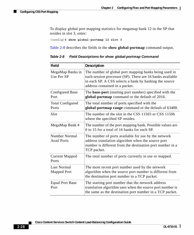
To display global port mapping statistics for megamap bank 12 in the SP that resides in slot 3, enter:
(config)# show global-portmap 12 slot 3
Table 2-8 describes the fields in the show global-portmap command output.
Table 2-8 Field Descriptions for show global-portmap Command
Field Description
MegaMap Banks in Use Per SP
The number of global port mapping banks being used in each session processor (SP). There are 16 banks available in each SP. A CSS selects a bank by hashing the source address contained in a packet.
Configured Base Port
The base-port (starting port number) specified with the global-portmap command or the default of 2016.
Total Configured Ports
The total number of ports specified with the global-portmap range command or the default of 63488.
Slot The number of the slot in the CSS 11503 or CSS 11506 where the specified SP resides.
MegaMap Bank # The number of the port mapping bank. Possible values are 0 to 15 for a total of 16 banks for each SP.
Number Normal Avail Ports
The number of ports available for use by the network address translation algorithm when the source port number is different from the destination port number in a TCP packet.
Current Mapped Ports
The total number of ports currently in use or mapped.
Last Normal Mapped Port
The most recent port number used by the network algorithm when the source port number is different from the destination port number in a TCP packet.
Equal Port Base Port
The starting port number that the network address translation algorithm uses when the source port number is the same as the destination port number in a TCP packet.
Chapter 2 Configuring Flow and Port Mapping ParametersConfiguring CSS Port Mapping
Configuring No-Flow Port MappingTo control the PAT range of DNS UDP source-port numbers greater than 1023 on a CSS, use the noflow-portmap command. This command is always enabled. However, before a CSS can use this command, you must use the flow-state command to disable DNS flows on the CSS. See the “Configuring the Flow-State Table” section.
Note The portmap command values configured in a source group take precedence over the noflow-portmap command values, unless you configure the portmap disable command. Refer to Chapter 3, Configuring Services, for details on configuring the portmap commands in a source group.
The syntax for this global configuration mode command is:
noflow-portmap base-port number1 range number2
The options and variables for this command are:
• base-port number1 - The starting port number for no-flow (DNS flows are disabled) port mapping on a CSS. Enter an integer from 2016 to 63456. The default is 2016.
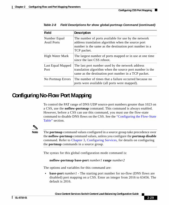
Number Equal Avail Ports
The number of ports available for use by the network address translation algorithm when the source port number is the same as the destination port number in a TCP packet.
High Water Mark The largest number of ports mapped or in use at one time since the last CSS reboot.
Last Equal Mapped Port
The last port number used by the network address translation algorithm when the source port number is the same as the destination port number in a TCP packet.
No Portmap Errors The number of times that a failure occurred because no ports were available (all ports were mapped).
Table 2-8 Field Descriptions for show global-portmap Command (continued)
Chapter 2 Configuring Flow and Port Mapping ParametersConfiguring CSS Port Mapping
Caution Changing the value of the number1 variable may cause port conflicts on existing flows.
• range number2 - The total number of ports in the port-map range that the CSS allocates to each session processor (SP). Each SP can use the full range of configured ports.
Caution Changing the value of the number2 variable may cause port conflicts on existing flows.
Enter an integer from 2048 to 63488. The default is 63488. If you enter a value that is not a multiple of 32, the CSS rounds up the value to the next possible multiple of 32.
Note If you enter a range value that exceeds the number of available ports, you get an error. To determine the number of available ports, subtract the starting port number from 65504.
For example, to specify a port map range, starting with port 4317, enter:
(config)# noflow-portmap base-port 4317 range 35421
To reset the starting port number and port-map range to their default values, enter:
(config)# no noflow-portmap
Displaying No-Flow Port Mapping StatisticsUse the show noflow-portmap command to display statistics for no-flow port mapping on a CSS. This command is available in all modes except RMON, URQL, and VLAN configuration modes.
Chapter 2 Configuring Flow and Port Mapping ParametersConfiguring CSS Port Mapping
The options and variables for this command are as follows:
• all-sps - Specifies the display of no-flow port-map information for all session processors (SPs) in the CSS.
• slot number - The chassis slot number where the module resides. For a CSS 11503, enter an integer from 1 to 3. For a CSS 11506, enter an integer from 1 to 6.
Note To display the available active slots in the CSS, enter the show noflow-portmap slot ? command. If you enter an invalid slot number, the CLI displays values for only the first two parameters listed in Table 2-9.
For example:
(config)# show noflow-portmap slot 3
Table 2-9 describes the fields in the show noflow-portmap command output.
Table 2-9 Field Descriptions for show noflow-portmap Command
Field Description
Configured Base Port
The starting port number specified by the noflow-portmap base-port command or the default of 2016
Total Configured Ports
The total number of ports specified by the noflow-portmap range command or the default of 63488
Slot The number of the slot in the CSS 11503 or CSS 11506 where the specified SP resides
Number Normal Avail Ports
The number of ports available for use by the network address translation algorithm when the source port number is different from the destination port number in a UDP packet
Current Mapped Ports
The total number of ports currently in use or mapped
Last Normal Mapped Port
The most recent port number used by the network address translation algorithm when the source port number is different from the destination port number in a UDP packet
Chapter 2 Configuring Flow and Port Mapping ParametersConfiguring CSS Port Mapping
Equal Port Base Port
The starting port number that the network address translation algorithm uses when the source port number is the same as the destination port number in a UDP packet
Number Equal Avail Ports
The number of ports available for use by the network address translation algorithm when the source port number is the same as the destination port number in a UDP packet
High Water Mark The largest number of ports mapped or in use at one time since the last CSS reboot.
Last Equal Mapped Port
The last port number used by the network address translation algorithm when the source port number was the same as the destination port number in a UDP packet
No Portmap Errors The number of times that a failure occurred because no ports were available (all ports were mapped)
Table 2-9 Field Descriptions for show noflow-portmap Command (continued)