Configuring for Network Management ApplicationsUsing SNMP Tools To Manage the Switch
Using SNMP Tools To Manage the Switch
Overview
You can manage the switch via SNMP from a network management station running an application such as ProCurve Manager (PCM) or ProCurve Manager Plus (PCM+). For more on PCM and PCM+, visit the ProCurve web site at:
http://www.procurve.com
Click on products index in the sidebar, then click on the appropriate link appearing under the Network Management heading.
This section includes:
■ An overview of SNMP management for the switch
■ Configuring the switches for:
• SNMP Communities (page 13-12)
• Trap Receivers and Authentication Traps (page 13-18)
■ Information on advanced management through RMON Support (page 13-24)
To implement SNMP management, the switch must have an IP address, configured either manually or dynamically (using DHCP or Bootp). If multiple VLANs are configured, each VLAN interface should have its own IP address. For DHCP use with multiple VLANs, see the chapter on VLANs in the Advanced Traffic Management Guide.
N o t e If you use the switch’s Authorized IP Managers and Management VLAN features, ensure that the SNMP management station and/or the choice of switch port used for SNMP access to the switch are compatible with the access controls enforced by these features. Otherwise, SNMP access to the switch will be blocked. For more on Authorized IP Managers, refer to the Access
Security Guide on the Documentation CD-ROM shipped with your switch. (For the latest version of this guide, visit the ProCurve web site.) For information on the Management VLAN feature, see the chapter on VLANs in the Advanced Traffic Management Guide.
13-3
Configuring for Network Management ApplicationsUsing SNMP Tools To Manage the Switch
SNMP Management Features
SNMP management features on the switch include:
■ SNMP version 1, version 2c or version 3 over IP
■ Security via configuration of SNMP communities (page 13-4)
■ Security via authentication and privacy for SNMP Version 3 access
■ Event reporting via SNMP
• Version 1 traps
• RMON
■ ProCurve Manager/Plus support
■ Flow sampling using either EASE or sFlow
■ Standard MIBs, such as the Bridge MIB (RFC 1493), Ethernet MAU MIB (RFC 1515), and others
The switch SNMP agent also uses certain variables that are included in a Hewlett-Packard proprietary MIB (Management Information Base) file. To ensure that you have the latest version in the database of your SNMP network management tool, you can copy the MIB file from the ProCurve Networking web site at:
http://www.procurve.com
Click on software, then MIBs.
Configuring for SNMP Access to the Switch
SNMP access requires an IP address and subnet mask configured on the switch. For managed switches, ProCurve recommends permanent IP addressing. (Refer to “IP Configuration” on page 8-3.)
Once an IP address has been configured, the main steps for configuring SNMP version 1 and version 2c access management features are:
1. Configure the appropriate SNMP communities. (Refer to “SNMP Commu-nities” on page 13-12.)
2. Configure the appropriate trap receivers. (Refer to “SNMP Notification and Traps” on page 13-18.)
In some networks, authorized IP manager addresses are not used. In this case, all management stations using the correct community name may access the switch with the View and Access levels that have been set for that community.
13-4
Configuring for Network Management ApplicationsUsing SNMP Tools To Manage the Switch
If you want to restrict access to one or more specific nodes, you can use the switch’s IP Authorized Manager feature. (Refer to the Access Security Guide for your switch.)
C a u t i o n The “public” community exists by default and is used by ProCurve’s network management applications. Deleting the “public” community disables many network management functions (such as auto-discovery, traffic monitoring, SNMP trap generation, and threshold setting). If security for network management is a concern, it is recommended that you change the write access for the “public” community to “Restricted”.
Configuring for SNMP Version 3 Access to the Switch
SNMP version 3 (SNMPv3) access requires an IP address and subnet mask configured on the switch. (See “IP Configuration” on page 8-3.) If you are using DHCP/Bootp to configure the switch, ensure that the DHCP/Bootp process provides the IP address. (See “DHCP/Bootp Operation” on page 8-12.)
Once an IP address has been configured, the main steps for configuring SNMP version 3 access management features are:
1. Enable SNMPv3 for operation on the switch (Refer to “SNMP Version 3 Commands” on page 13-6).
2. Configure the appropriate SNMP users. (Refer to “SNMP Version 3 Users” on page 13-8).
3. Configure the appropriate SNMP communities. (Refer to “SNMP Commu-nities” on page 13-12.)
4. Configure the appropriate trap receivers. (Refer to “SNMP Notification and Traps” on page 13-18.)
In some networks, authorized IP manager addresses are not used. In this case, all management stations using the correct User and community name may access the switch with the View and Access levels that have been set for that community. If you want to restrict access to one or more specific nodes, you can use the switch’s IP Authorized Manager feature. (Refer to the Access
Security Guide for your switch.)
13-5
Configuring for Network Management ApplicationsUsing SNMP Tools To Manage the Switch
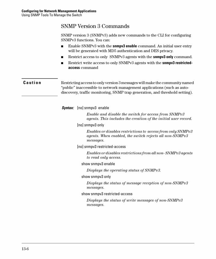
SNMP Version 3 Commands
SNMP version 3 (SNMPv3) adds new commands to the CLI for configuring SNMPv3 functions. You can:
■ Enable SNMPv3 with the snmpv3 enable command. An initial user entry will be generated with MD5 authentication and DES privacy.
■ Restrict access to only SNMPv3 agents with the snmpv3 only command.
■ Restrict write access to only SNMPv3 agents with the snmpv3 restricted-access command
C a u t i o n Restricting access to only version 3 messages will make the community named “public” inaccessible to network management applications (such as auto-discovery, traffic monitoring, SNMP trap generation, and threshold setting).
Syntax: [no] snmpv3 enable
Enable and disable the switch for access from SNMPv3
agents. This includes the creation of the initial user record.
[no] snmpv3 only
Enables or disables restrictions to access from only SNMPv3
agents. When enabled, the switch rejects all non-SNMPv3
messages.
[no] snmpv3 restricted-access
Enables or disables restrictions from all non- SNMPv3 agents
to read only access.
show snmpv3 enable
Displays the operating status of SNMPv3.
show snmpv3 only
Displays the status of message reception of non-SNMPv3
messages.
show snmpv3 restricted-access
Displays the status of write messages of non-SNMPv3
messages.
13-6
Configuring for Network Management ApplicationsUsing SNMP Tools To Manage the Switch
SNMPv3 Enable
The snmpv3 enable command starts a dialog that performs three functions: enabling the switch to receive SNMPv3 messages, configuring the initial users, and, optionally, to restrict non version-3 messages to “read only”. Figure 13-1 shows and example of this dialog.
N o t e : S N M P Ve r s i o n 3 I n i t i a l U s e r s
For most SNMPv3 management software to be able to create new users, they must have an initial user record clone. These records can be downgraded, (given fewer features), but not upgraded with new features added. For this reason ProCurve recommends that you create a second user with SHA and DES at when you enable SNMPv3
Figure 13-1. Example of SNMP version 3 Enable Command
Enable
Create initial user models for SNMPv3 management applications.
Set restriction onnon-SNMPv3 messages.
13-7
Configuring for Network Management ApplicationsUsing SNMP Tools To Manage the Switch
SNMP Version 3 Users
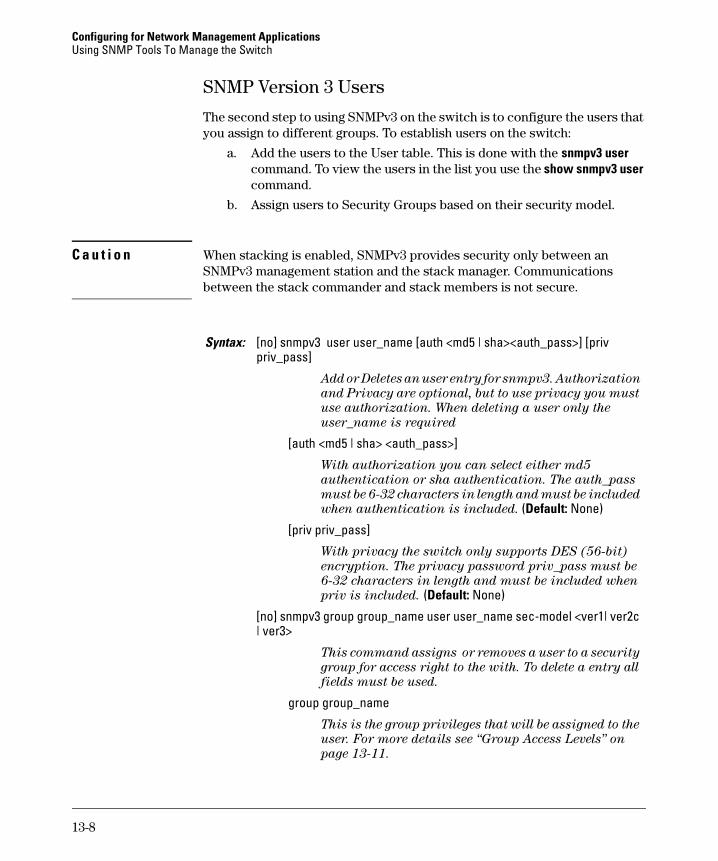
The second step to using SNMPv3 on the switch is to configure the users that you assign to different groups. To establish users on the switch:
a. Add the users to the User table. This is done with the snmpv3 user command. To view the users in the list you use the show snmpv3 user command.
b. Assign users to Security Groups based on their security model.
C a u t i o n When stacking is enabled, SNMPv3 provides security only between an SNMPv3 management station and the stack manager. Communications between the stack commander and stack members is not secure.
Add or Deletes an user entry for snmpv3. Authorization
and Privacy are optional, but to use privacy you must
use authorization. When deleting a user only the
user_name is required
[auth <md5 | sha> <auth_pass>]
With authorization you can select either md5
authentication or sha authentication. The auth_pass
must be 6-32 characters in length and must be included
when authentication is included. (Default: None)
[priv priv_pass]
With privacy the switch only supports DES (56-bit)
encryption. The privacy password priv_pass must be
6-32 characters in length and must be included when
priv is included. (Default: None)
[no] snmpv3 group group_name user user_name sec-model <ver1| ver2c | ver3>
This command assigns or removes a user to a security
group for access right to the with. To delete a entry all
fields must be used.
group group_name
This is the group privileges that will be assigned to the
user. For more details see “Group Access Levels” on
page 13-11.
13-8
Configuring for Network Management ApplicationsUsing SNMP Tools To Manage the Switch
To establish a user you must first add the user names to the list of known users. Add user names with the snmpv3 user CLI command.
Figure 13-2. Adding and showing Users for SNMPv3
[no] snmpv3 group group_name user user_name sec-model <ver1| ver2c | ver3> (— Continued —)
user user_nameThis is the user to be added to the access group. This must match the user name added with the snmpv3 user command.
sec-model <ver1 | ver2c | ver3>
This defines which security model to use for the added
user. A SNMPv3 access Group should only use the ver3
security model.
Add user Network Admin with no Authentication or Privacy
Add user Network Mgr with authentication and privacy
Privacy is used and the password is set privpass
Authentication is set to Md5 and the password is authpass
13-9
Configuring for Network Management ApplicationsUsing SNMP Tools To Manage the Switch
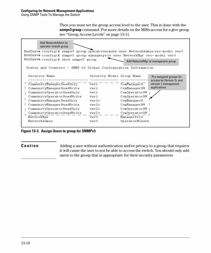
Then you must set the group access level to the user. This is done with the snmpv3 group command. For more details on the MIBs access for a give group see “Group Access Levels” on page 13-11.
Figure 13-3. Assign Users to group for SNMPv3
C a u t i o n Adding a user without authentication and/or privacy to a group that requires it will cause the user to not be able to access the switch. You should only add users to the group that is appropriate for their security parameters
Add NetworkAdmin to operator noauth group
Add NetwrokMgr to managerpriv group
Pre-assigned groups for access by Version 2c and version 1 management applications
13-10
Configuring for Network Management ApplicationsUsing SNMP Tools To Manage the Switch
Group Access Levels
The switch supports eight predefined group access levels. There are four levels for use with version 3 users and four are used for access by version 2c or version 1 management applications.
Each view allows you to view or modify a different set of MIBs.
■ Manager Read View – access to all managed objects
■ Manager Write View – access to all managed objects except the follow-ing: vacmContextTable, vacmAccessTable, vacmViewTreeFamilyTable
■ OperatorReadView – no access to icfSecurityMIB, ProCurveIpTftp-Mode, vacmContextTable, vacmAccessTable, vacmViewTreeFami-lyTable, usmUserTable, snmpCommunityTable
■ Discovery View – Access limited to samplingProbe MIB.
N o t e All access groups and views are predefined on the switch. There is no method to modify or add groups or views to those that are pre-defined on the switch.
Group Name Group Access Type Group Read View Group Write View
managerpriv Ver3 Must have Authentication and Privacy
ManagerReadView ManagerWriteView
managerauth Ver3 Must have Authentication ManagerReadView ManagerWriteView
operatorauth Ver3 Must have Authentication OperatorReadView DiscoveryView
operatornoauth Ver3 No Authentication OperatorReadView DiscoveryView
commanagerrw Ver2c or Ver1 ManagerReadView ManagerWriteView
commanagerr Ver2c or Ver1 ManagerReadView DiscoveryView
comoperatorrw Ver2c or Ver1 OperatorReadView OperatorReadView
comoperatorr Ver2c or Ver1 OperatorReadView DiscoveryView
13-11
Configuring for Network Management ApplicationsUsing SNMP Tools To Manage the Switch
SNMP Communities
SNMP commuities are supported by the switch to allow management application that use version 2c or version 1 to access the switch. The communities are mapped to Group Access Levels that are used for version 2c or version 1 support. For more information see “Group Access Levels” on page 13-11. This mapping will happen automatically based on the communities access privileges, but special mappings can be added with the snmpv3 community command.
Syntax: [no] snmpv3 community This command maps or removes a mapping of a community name to a group access level. To remove a mapping you only need the index_name.
< index < index-name >>
This is an index number or title for the mapping. The values of 1-5 are reserved and can not be mapped.
< name < com-name >>
This is the community name that is being mapped to a group access level
< sec-name < security-name >>
This is the group level that the community is being mapped. For more information see “Group Access Levels” on page 13-11.
< tag < tag-value >>
This is used to specify which target address may have access via this index reference.
13-12
Configuring for Network Management ApplicationsUsing SNMP Tools To Manage the Switch
Figure 13-4 shows the assigning of the Operator community on MgrStation1 to the CommunityOperatorReadWrite group. Any other Operator only has an access level of CommunityOperatorReadOnly.
Figure 13-4. Assigning a Community to a Group Access Level
Table 13-1. SNMP Community Features
Use SNMP communities to restrict access to the switch by SNMP management stations by adding, editing, or deleting SNMP communities. You can configure up to five SNMP communities, each with either an operator-level or a manager-level view, and either restricted or unrestricted write access.
Using SNMP requires that the switch have an IP address and subnet mask compatible with your network.
Add mapping to allow write access for Operator community on MgrStation1
Two Operator Access Levels
Feature Default Menu CLI Web
show SNMP communities n/a page 13-14
page 13-16
—
configure identity information none — page 13-17
configure community namesMIB view for a community name
(operator, manager)write access for defaultcommunity name
public
manager
unrestricted
page 13-14
“ “ “
page 13-17 “ “ “
—
13-13
Configuring for Network Management ApplicationsUsing SNMP Tools To Manage the Switch
C a u t i o n Deleting or changing the community named “public” prevents network management applications (such as auto-discovery, traffic monitoring, SNMP trap generation, and threshold setting) from operating in the switch. (Changing or deleting the “public” name also generates an Event Log message.) If security for network management is a concern, it is recommended that you change the write access for the “public” community to “Restricted”.
Menu: Viewing and Configuring non-SNMP version 3 Communities
To View, Edit, or Add SNMP Communities:
1. From the Main Menu, Select:
2. Switch Configuration...6. SNMP Community Names
Figure 13-5. The SNMP Communities Screen (Default Values)
2. Press [A] (for Add) to display the following screen:
Add and Edit options are used to modify the SNMP options. See figure 8-2.
Note: This screen gives an overview of the SNMP communities that are currently configured. All fields in this screen are read-only.
13-14
Configuring for Network Management ApplicationsUsing SNMP Tools To Manage the Switch
Figure 13-6. The SNMP Add or Edit Screen
Need Help? If you need information on the options in each field, press [Enter] to move the cursor to the Actions line, then select the Help option on the Actions line. When you are finished with Help, press [E] (for Edit) to return the cursor to the parameter fields.
3. Enter the name you want in the Community Name field, and use the Space bar to select the appropriate value in each of the other fields. (Use the [Tab] key to move from one field to the next.)
4. Press [Enter], then [S] (for Save).
If you are adding a community, the fields in this screen are blank.
If you are editing an existing community, the values for the currently selected Community appear in the fields.
Type the value for this field.
Use the Space bar to select values for other fields
13-15
Configuring for Network Management ApplicationsUsing SNMP Tools To Manage the Switch
CLI: Viewing and Configuring SNMP Community Names
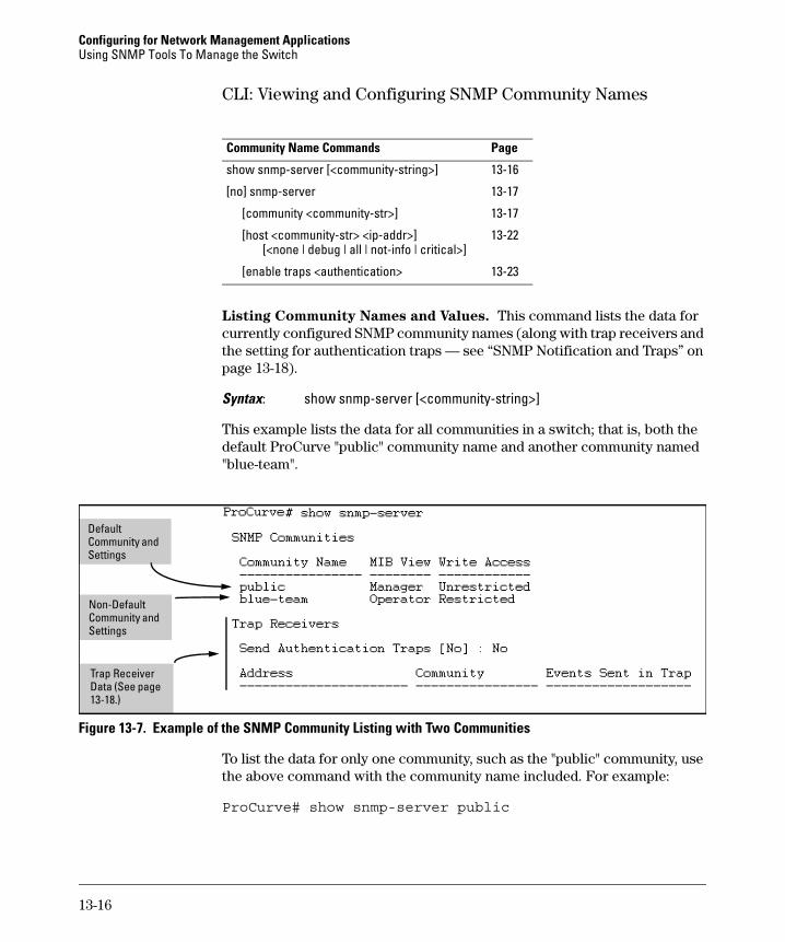
Listing Community Names and Values. This command lists the data for currently configured SNMP community names (along with trap receivers and the setting for authentication traps — see “SNMP Notification and Traps” on page 13-18).
Syntax: show snmp-server [<community-string>]
This example lists the data for all communities in a switch; that is, both the default ProCurve "public" community name and another community named "blue-team".
Figure 13-7. Example of the SNMP Community Listing with Two Communities
To list the data for only one community, such as the "public" community, use the above command with the community name included. For example:
Configuring for Network Management ApplicationsUsing SNMP Tools To Manage the Switch
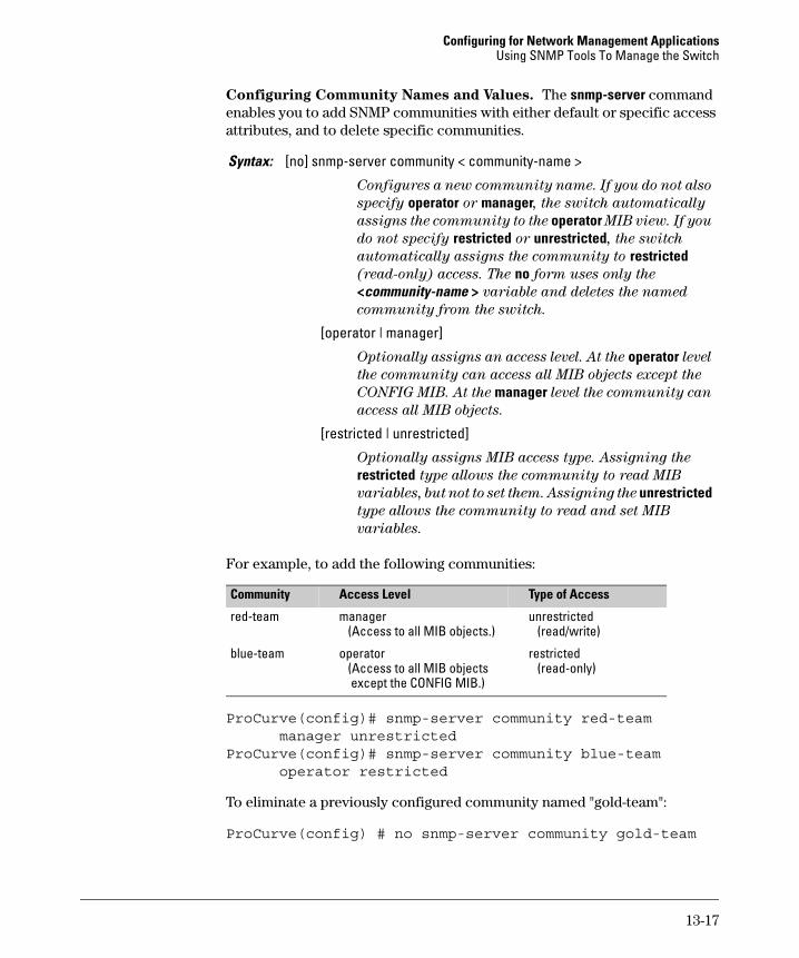
Configuring Community Names and Values. The snmp-server command enables you to add SNMP communities with either default or specific access attributes, and to delete specific communities.
For example, to add the following communities:
ProCurve(config)# snmp-server community red-team manager unrestricted
ProCurve(config)# snmp-server community blue-team operator restricted
To eliminate a previously configured community named "gold-team":
ProCurve(config) # no snmp-server community gold-team
Syntax: [no] snmp-server community < community-name >
Configures a new community name. If you do not also
specify operator or manager, the switch automatically
assigns the community to the operator MIB view. If you
do not specify restricted or unrestricted, the switch
automatically assigns the community to restricted
(read-only) access. The no form uses only the
<community-name > variable and deletes the named
community from the switch.
[operator | manager]
Optionally assigns an access level. At the operator level
the community can access all MIB objects except the
CONFIG MIB. At the manager level the community can
access all MIB objects.
[restricted | unrestricted]
Optionally assigns MIB access type. Assigning the
restricted type allows the community to read MIB
variables, but not to set them. Assigning the unrestricted
type allows the community to read and set MIB
variables.
Community Access Level Type of Access
red-team manager (Access to all MIB objects.)
unrestricted (read/write)
blue-team operator (Access to all MIB objects except the CONFIG MIB.)
restricted (read-only)
13-17
Configuring for Network Management ApplicationsUsing SNMP Tools To Manage the Switch
SNMP Notification and Traps
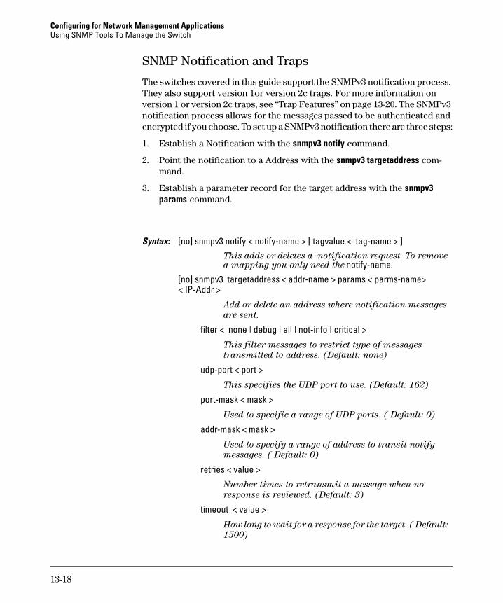
The switches covered in this guide support the SNMPv3 notification process. They also support version 1or version 2c traps. For more information on version 1 or version 2c traps, see “Trap Features” on page 13-20. The SNMPv3 notification process allows for the messages passed to be authenticated and encrypted if you choose. To set up a SNMPv3 notification there are three steps:
1. Establish a Notification with the snmpv3 notify command.
2. Point the notification to a Address with the snmpv3 targetaddress com-mand.
3. Establish a parameter record for the target address with the snmpv3 params command.
Syntax: [no] snmpv3 notify < notify-name > [ tagvalue < tag-name > ]This adds or deletes a notification request. To remove a mapping you only need the notify-name.
messages passed to the target address. If ver3 is used
and sec-model is ver3 then you must select a security
services level (< noauth | auth | priv >)
tagvalue matches taglist value.
params value matches params name.
Both ver3 means you must select a security service level.
13-19
Configuring for Network Management ApplicationsUsing SNMP Tools To Manage the Switch
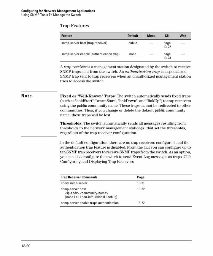
Trap Features
A trap receiver is a management station designated by the switch to receive SNMP traps sent from the switch. An authentication trap is a specialized SNMP trap sent to trap receivers when an unauthorized management station tries to access the switch.
N o t e Fixed or "Well-Known" Traps: The switch automatically sends fixed traps (such as "coldStart", "warmStart", "linkDown", and "linkUp") to trap receivers using the public community name. These traps cannot be redirected to other communities. Thus, if you change or delete the default public community name, these traps will be lost.
Thresholds: The switch automatically sends all messages resulting from thresholds to the network management station(s) that set the thresholds, regardless of the trap receiver configuration.
In the default configuration, there are no trap receivers configured, and the authentication trap feature is disabled. From the CLI you can configure up to ten SNMP trap receivers to receive SNMP traps from the switch. As an option, you can also configure the switch to send Event Log messages as traps. CLI: Configuring and Displaying Trap Receivers
Feature Default Menu CLI Web
snmp-server host (trap receiver) public — page 13-22
Configuring for Network Management ApplicationsUsing SNMP Tools To Manage the Switch
Using the CLI To List Current SNMP Trap Receivers.
This command lists the currently configured trap receivers and the setting for authentication traps (along with the current SNMP community name data — see “SNMP Communities” on page 13-12).
In the next example, the show snmp-server command shows that the switch has been previously configured to send SNMP traps to management stations belonging to the “public”, “red-team”, and “blue-team” communities.
Figure 13-9. Example of Show SNMP-Server Listing
Syntax: show snmp-server
Displays current community and trap receiver data.
Example of Community Name Data (See page 13-12.)
Example of Trap Receiver Data
Authentication Trap Setting
13-21
Configuring for Network Management ApplicationsUsing SNMP Tools To Manage the Switch
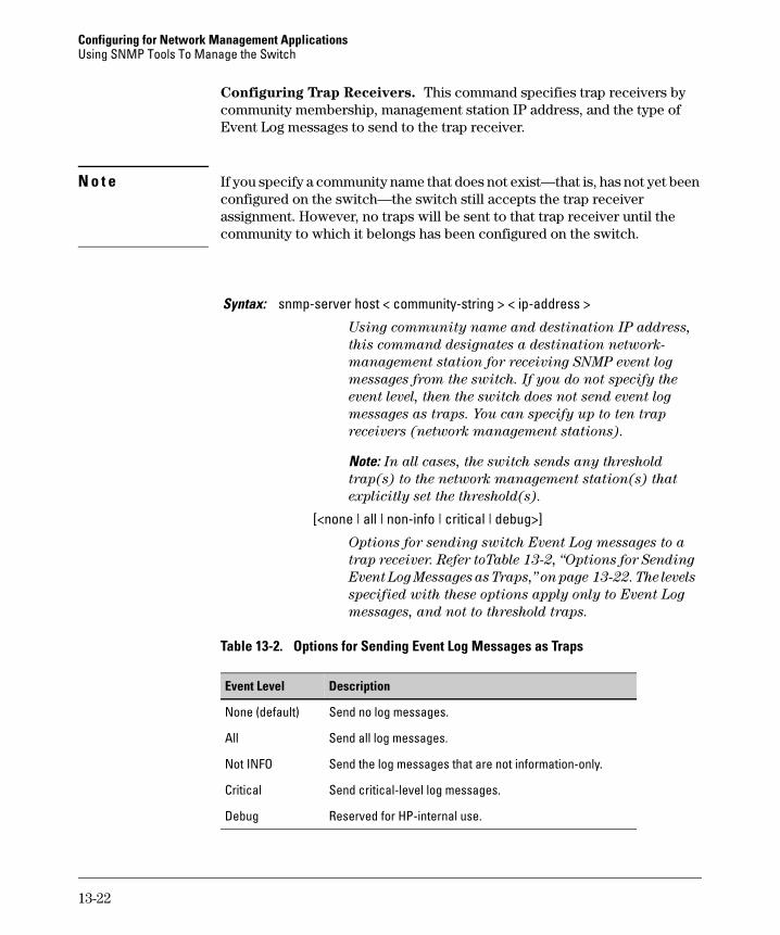
Configuring Trap Receivers. This command specifies trap receivers by community membership, management station IP address, and the type of Event Log messages to send to the trap receiver.
N o t e If you specify a community name that does not exist—that is, has not yet been configured on the switch—the switch still accepts the trap receiver assignment. However, no traps will be sent to that trap receiver until the community to which it belongs has been configured on the switch.
Table 13-2. Options for Sending Event Log Messages as Traps
messages from the switch. If you do not specify the
event level, then the switch does not send event log
messages as traps. You can specify up to ten trap
receivers (network management stations).
Note: In all cases, the switch sends any threshold
trap(s) to the network management station(s) that
explicitly set the threshold(s).
[<none | all | non-info | critical | debug>]
Options for sending switch Event Log messages to a
trap receiver. Refer toTable 13-2, “Options for Sending
Event Log Messages as Traps,” on page 13-22. The levels
specified with these options apply only to Event Log
messages, and not to threshold traps.
Event Level Description
None (default) Send no log messages.
All Send all log messages.
Not INFO Send the log messages that are not information-only.
Critical Send critical-level log messages.
Debug Reserved for HP-internal use.
13-22
Configuring for Network Management ApplicationsUsing SNMP Tools To Manage the Switch
For example, to configure a trap receiver in a community named "red-team" with an IP address of 10.28.227.130 to receive only "critical" log messages:
N o t e s To replace one community name with another for the same IP address, you must use no snmp-server host < community-name> < ip-address > to delete the unwanted community name. Otherwise, adding a new community name with an IP address already in use with another community name simply creates two allowable community name entries for the same management station.
If you do not specify the event level ([<none | all | non-info | critical | debug>]) then the switch does not send event log messages as traps. "Well-Known" traps and threshold traps (if configured) will still be sent.
Using the CLI To Enable Authentication Traps
N o t e For this feature to operate, one or more trap receivers must be configured on the switch. See “Configuring Trap Receivers” on page 13-22.
Check the Event Log in the console interface to help determine why the authentication trap was sent. (Refer to “Using Logging To Identify Problem Sources” on page C-23.)
Enables or disables sending an authentication trap to the
configured trap receiver(s) if an unauthorized management
station attempts to access the switch.
13-23
Configuring for Network Management ApplicationsUsing SNMP Tools To Manage the Switch
Advanced Management: RMON
The switches covered in this guide support RMON (Remote Monitoring) on all connected network segments. This allows for troubleshooting and optimizing your network. The following RMON groups are supported:
■ Ethernet Statistics (except the numbers of packets of different frame sizes)
■ Alarm
■ History (of the supported Ethernet statistics)
■ Event
The RMON agent automatically runs in the switch. Use the RMON management station on your network to enable or disable specific RMON traps and events.
13-24
Configuring for Network Management ApplicationsLLDP (Link-Layer Discovery Protocol)
LLDP (Link-Layer Discovery Protocol)
To standardize device discovery on all ProCurve switches, LLDP has been
implemented while offering limited read-only support for CDP as
documented in this manual. For current information on your switch model,
consult the latest Release Notes (available on the ProCurve Networking web
site). If LLDP has not yet been implemented (or if you are running an older
version of software), consult a previous version of the Management and
Configuration Guide for device discovery details.
Introduction
LLDP Features
The Link Layer Discovery Protocol (LLDP) provides a standards-based method for enabling switches to advertise themselves to adjacent devices and to learn about adjacent LLDP devices.
An SNMP utility can progressively discover LLDP devices in a network by:
1. Reading a given device’s Neighbors table (in the Management Information Base, or MIB) to learn about other, neighboring LLDP devices.
2. Using the information learned in step 1 to find and read the neighbor devices’ Neighbors tables to learn about additional devices, and so on.
Feature Default Menu CLI Web
View the switch’s LLDP configuration n/a — page 13-32 —
Enable or disable LLDP on the switch Enabled — page 13-34 —
Change the transmit interval (refresh-interval) for LLDP packets
30 seconds — page 13-35 —
Change the holdtime multiplier for LLDP Packets(holdtime-multiplier x refresh-interval = time-to-live)
4 seconds — page 13-35 —
Change the delay interval between advertisements 2 seconds — page 13-36 —
Displaying Advertisement Data and Statistics n/a — page 13-41 —
13-25
Configuring for Network Management ApplicationsLLDP (Link-Layer Discovery Protocol)
Also, by using show commands to access the switch’s neighbor database for information collected by an individual switch, system administrators can learn about other devices connected to the switch, including device type (capability) and some configuration information.
LLDP Terminology
Adjacent Device: Refer to “Neighbor or Neighbor Device”.
Advertisement: See LLDPDU.
Active Port: A port linked to another active device (regardless of whether STP is blocking the link).
LLDP: Link Layer Discovery Protocol. ProCurve switches are compatible with IEEE 802.1AB-2005.
LLDP-Aware: A device that has LLDP in its operating code, regardless of whether LLDP is enabled or disabled.
LLDP Device: A switch, server, router, or other device running LLDP.
LLDP Neighbor: An LLDP device that is either directly connected to another LLDP device or connected to that device by another, non-LLDP Layer 2 device (such as a hub) Note that an 802.1D-compliant switch does not forward LLDP data packets even if it is not LLDP-aware.
LLDPDU (LLDP Data Unit): LLDP data packets are transmitted on active links and include multiple TLVs containing global and per-port switch information. In this guide, LLDPDUs are termed “advertisements” or “packets”.
MIB (Management Information Base): An internal database the switch maintains for configuration and performance information.
Neighbor: See “LLDP Neighbor”.
Non_LLDP Device: A device that is not capable of LLDP operation.
TLV (Type-Length-Value): A data unit that includes a data type field, a data unit length field (in bytes), and a field containing the actual data the unit is designed to carry (as an alphanumeric string, a bitmap, or a subgroup of information). Some TLVs include subelements that occur as separate data points in displays of information maintained by the switch for LLDP advertisements. (That is, some TLVs include multiple data points or subelements.)
13-26
Configuring for Network Management ApplicationsLLDP (Link-Layer Discovery Protocol)
General LLDP Operation
An LLDP packet contains data about the transmitting switch and port. The switch advertises itself to adjacent (neighbor) devices by transmitting LLDP data packets out all ports on which outbound LLDP is enabled, and reading LLDP advertisements from neighbor devices on ports that are inbound LLDP-enabled. (LLDP is a one-way protocol and does not include any acknowledgement mechanism.) An LLDP-enabled port receiving LLDP packets inbound from neighbor devices stores the packet data in a Neighbor database (MIB).
N o t e Ports can also be enabled for reading CDP packets and storing the CDP data in an LLDP-compatible version. See “LLDP and CDP Data Management” on page 13-50 for details.
Packet Boundaries in a Network Topology■ Where multiple LLDP devices are directly connected, an outbound LLDP
packet travels only to the next LLDP device. An LLDP-capable device does not forward LLDP packets to any other devices, regardless of whether they are LLDP-capable.
■ An intervening hub or repeater forwards the LLDP packets it receives in the same manner as any other multicast packets it receives. Thus, two LLDP switches joined by a hub or repeater handle LLDP traffic in the same way that they would if directly connected.
■ Any intervening 802.1D device, or Layer-3 device that is either LLDP-unaware or has disabled LLDP operation, drops the packet.
LLDP Configuration Options
Enable or Disable LLDP on the Switch. In the default configuration, LLDP is globally enabled on the switch. To prevent transmission or receipt of LLDP traffic, you can disable LLDP operation (page 13-34).
Change the Frequency of LLDP Packet Transmission to Neighbor
Devices. On a global basis, you can increase or decrease the frequency of outbound LLDP advertisements (page 13-35).
Change the Time-To-Live for LLDP Packets Sent to Neighbors. On a global basis, you can increase or decrease the time that the information in an LLDP packet outbound from the switch will be maintained in a neighbor LLDP device (page 13-35).
13-27
Configuring for Network Management ApplicationsLLDP (Link-Layer Discovery Protocol)
Transmit and Receive Mode. With LLDP enabled, the switch periodically transmits an LLDP advertisement (packet) out each active port enabled for outbound LLDP transmissions, and receives LLDP advertisements on each active port enabled to receive LLDP traffic (page 13-39). Per-Port configuration options include four modes:
■ Transmit and Receive (tx_rx): This is the default setting on all ports. It enables a given port to both transmit and receive LLDP packets, and to store the data from received (inbound) LLDP packets in the switch’s MIB.
■ Transmit only (txonly): This setting enables a port to transmit LLDP packets that can be read by LLDP neighbors. However, the port drops inbound LLDP packets from LLDP neighbors without reading them. This prevents the switch from learning about LLDP neighbors on that port.
■ Receive only (rxonly): This setting enables a port to receive and read LLDP packets from LLDP neighbors, and to store the packet data in the switch’s MIB. However, the port does not transmit outbound LLDP packets. This prevents LLDP neighbors from learning about the switch through that port.
■ Disable (disable): This setting disables LLDP packet transmissions and reception on a port. In this state, the switch does not use the port for either learning about LLDP neighbors or informing LLDP neighbors of its pres-ence.
SNMP Notification. You can enable the the switch to send a notification to any configured SNMP trap receiver(s) when the switch detects a remote LLDP data change on an LLDP-enabled port (page 13-37).
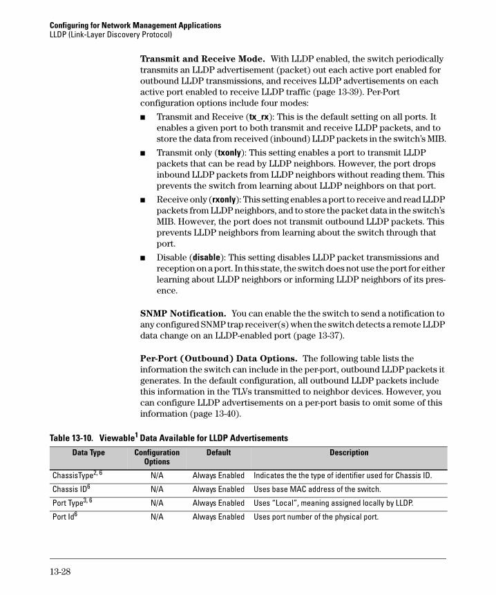
Per-Port (Outbound) Data Options. The following table lists the information the switch can include in the per-port, outbound LLDP packets it generates. In the default configuration, all outbound LLDP packets include this information in the TLVs transmitted to neighbor devices. However, you can configure LLDP advertisements on a per-port basis to omit some of this information (page 13-40).
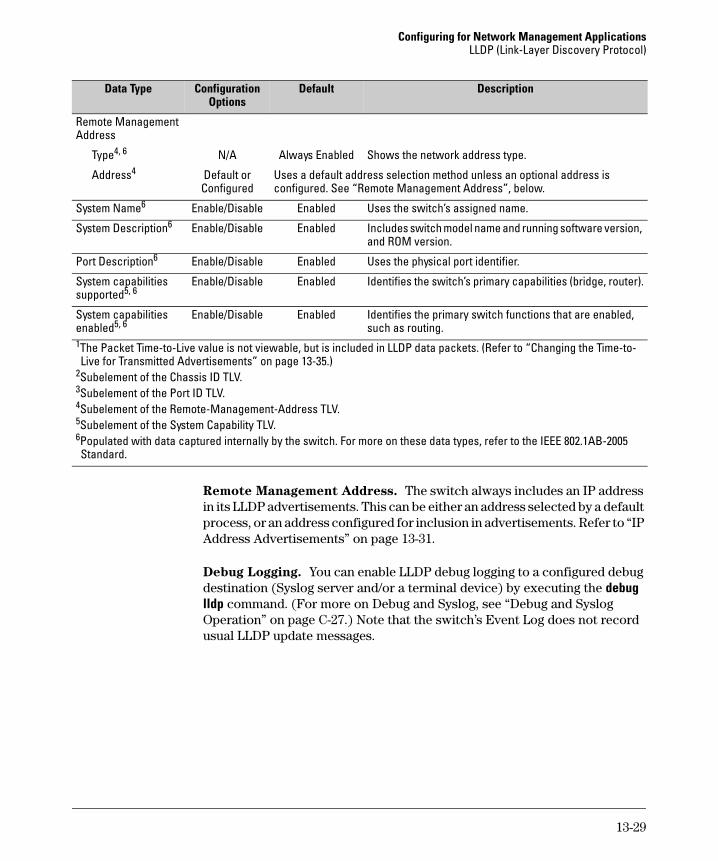
Table 13-10. Viewable1 Data Available for LLDP Advertisements
Data Type Configuration Options
Default Description
ChassisType2, 6 N/A Always Enabled Indicates the the type of identifier used for Chassis ID.
Chassis ID6 N/A Always Enabled Uses base MAC address of the switch.
Port Type3, 6 N/A Always Enabled Uses “Local”, meaning assigned locally by LLDP.
Port Id6 N/A Always Enabled Uses port number of the physical port.
13-28
Configuring for Network Management ApplicationsLLDP (Link-Layer Discovery Protocol)
Remote Management Address. The switch always includes an IP address in its LLDP advertisements. This can be either an address selected by a default process, or an address configured for inclusion in advertisements. Refer to “IP Address Advertisements” on page 13-31.
Debug Logging. You can enable LLDP debug logging to a configured debug destination (Syslog server and/or a terminal device) by executing the debug lldp command. (For more on Debug and Syslog, see “Debug and Syslog Operation” on page C-27.) Note that the switch’s Event Log does not record usual LLDP update messages.
Remote Management Address
Type4, 6 N/A Always Enabled Shows the network address type.
Address4 Default orConfigured
Uses a default address selection method unless an optional address is configured. See “Remote Management Address”, below.
System Name6 Enable/Disable Enabled Uses the switch’s assigned name.
System Description6 Enable/Disable Enabled Includes switch model name and running software version, and ROM version.
Port Description6 Enable/Disable Enabled Uses the physical port identifier.
System capabilities supported5, 6
Enable/Disable Enabled Identifies the switch’s primary capabilities (bridge, router).
System capabilities enabled5, 6
Enable/Disable Enabled Identifies the primary switch functions that are enabled, such as routing.
1The Packet Time-to-Live value is not viewable, but is included in LLDP data packets. (Refer to “Changing the Time-to-Live for Transmitted Advertisements” on page 13-35.)
2Subelement of the Chassis ID TLV.3Subelement of the Port ID TLV.4Subelement of the Remote-Management-Address TLV.5Subelement of the System Capability TLV.6Populated with data captured internally by the switch. For more on these data types, refer to the IEEE 802.1AB-2005 Standard.
Data Type Configuration Options
Default Description
13-29
Configuring for Network Management ApplicationsLLDP (Link-Layer Discovery Protocol)
Options for Reading LLDP Information Collected by the Switch
You can extract LLDP information from the switch to identify adjacent LLDP devices. Options include:
■ Using the switch’s show lldp info command options to display data collected on adjacent LLDP devices—as well as the local data the switch is transmitting to adjacent LLDP devices (page 13-32).
■ Using an SNMP application that is designed to query the Neighbors MIB for LLDP data to use in device discovery and topology mapping. (This includes CDP data the switch has read and mapped to the LLDP counterpart.)
■ Using the walkmib command to display a listing of the LLDP MIB objects
LLDP Standards Compatibility
The features covered by this guide for the Series 2600 switches are compatible with the following LLDP-related standards:
■ IEEE 802.1AB-2005
■ RFC 2922 (PTOPO, or Physical Topology MIB)
■ RFC 2737 (Entity MIB)
■ RFC 2863 (Interfaces MIB)
13-30
Configuring for Network Management ApplicationsLLDP (Link-Layer Discovery Protocol)
LLDP Operating RulesPort Trunking. LLDP manages trunked ports individually. That is, trunked ports are configured individually for LLDP operation, in the same manner as non-trunked ports. Also, LLDP sends separate advertisements on each port in a trunk, and not on a per-trunk basis. Similarly, LLDP data received through trunked ports is stored individually, per-port.
IP Address Advertisements. In the default operation, if a port belongs to only one static VLAN, then the port advertises the lowest-order IP address configured on that VLAN. If a port belongs to multiple VLANs, then the port advertises the lowest-order IP address configured on the VLAN with the lowest VID. If the qualifying VLAN does not have an IP address, the port advertises 127.0.0.1 as its IP address. For example, if the port is a member of the default VLAN (VID = 1), and there is an IP address configured for the default VLAN, then the port advertises this IP address. In the default operation, the IP address that LLDP uses can be an address acquired by DHCP or Bootp.
You can override the default operation by configuring the port to advertise any IP address that is manually configured on the switch, even if the port does not belong to the VLAN configured with the selected IP address (page 13-39). (Note that LLDP cannot be configured through the CLI to advertise an addresses acquired through DHCP or Bootp. However, as mentioned above, in the default LLDP configuration, if the lowest-order IP address on the VLAN with the lowest VID for a given port is a DHCP or Bootp address, then the switch includes this address in its LLDP advertisements unless another address is configured for advertisements on that port.) Also, although LLDP allows configuring multiple remote management addresses on a port, only the lowest-order address configured on the port will be included in outbound advertisements. Attempting to use the CLI to configure LLDP with an IP address that is either not configured on a VLAN, or has been acquired by DHCP or Bootp results in the following error message.
xxx.xxx.xxx.xxx: This IP address is not configured or is a DHCP address.
Spanning-Tree Blocking. Spanning tree does not prevent LLDP packet transmission or receipt on STP-blocked links.
802.1x Blocking. Ports blocked by 802.1x operation do not allow transmission or receipt of LLDP packets.
13-31
Configuring for Network Management ApplicationsLLDP (Link-Layer Discovery Protocol)
LLDP Operation and Commands
In the default configuration, LLDP is enabled and in both transmit and receive mode on all active ports. The LLDP configuration includes global settings that apply to all active ports on the switch, and per-port settings that affect only the operation of the specified ports.
Viewing the Current LLDP Configuration
Displaying the Global LLDP, Port Admin, and SNMP Notification
Status. This command displays the switch’s general LLDP configuration status, including some per-port information affecting advertisement traffic and trap notifications.
Displays the LLDP global configuration, LLDP port status, and
SNMP notification status. For information on port admin
status, refer to “Configuring Per-Port LLDP Transmit and
Receive Modes” on page 13-39.
13-32
Configuring for Network Management ApplicationsLLDP (Link-Layer Discovery Protocol)
For example, show lldp config produces the following display when the switch is in the default LLDP configuration:
Figure 13-1. Example of Viewing the General LLDP Configuration
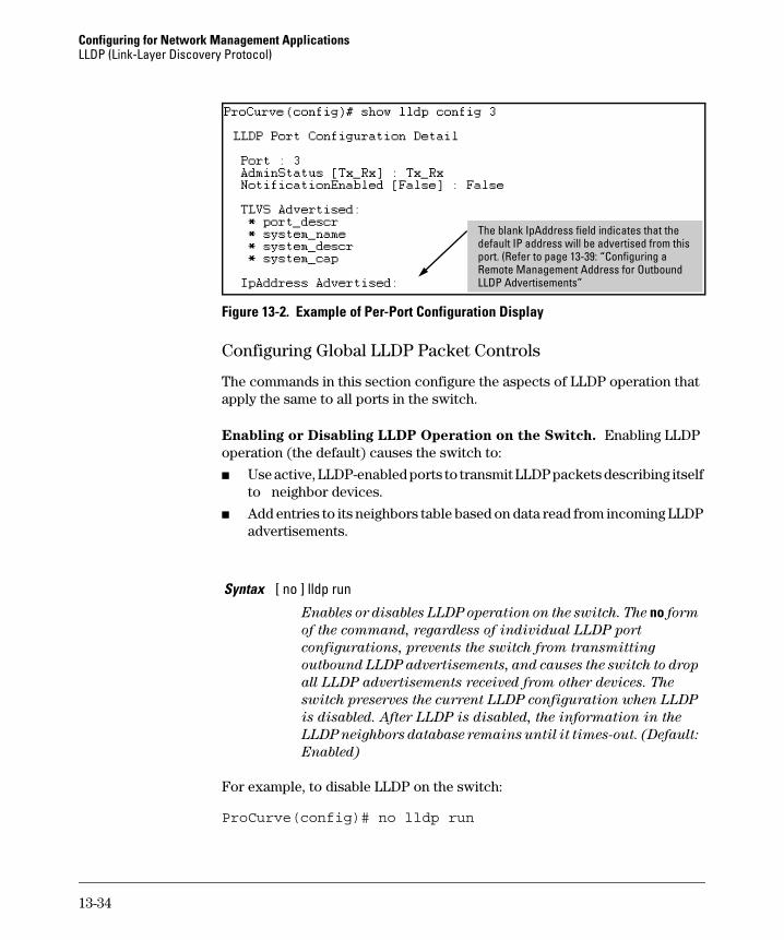
Displaying Port Configuration Details. This command displays the port-specific configuration, including .
Syntax show lldp config < port-list >
Displays the LLDP port-specific configuration for all ports in < port-list >, including which optional TLVs and any non-default
IP address that are included in the port’s outbound
advertisements. For information on the notification setting,
refer to “Configuring SNMP Notification Support” on page
13-37. For information on the other configurable settings
displayed by this command, refer to “Configuring Per-Port
LLDP Transmit and Receive Modes” on page 13-39.
Note: This value corresponds to the lldp refresh-interval command (page 13-35).
13-33
Configuring for Network Management ApplicationsLLDP (Link-Layer Discovery Protocol)
Figure 13-2. Example of Per-Port Configuration Display
Configuring Global LLDP Packet Controls
The commands in this section configure the aspects of LLDP operation that apply the same to all ports in the switch.
Enabling or Disabling LLDP Operation on the Switch. Enabling LLDP operation (the default) causes the switch to:
■ Use active, LLDP-enabled ports to transmit LLDP packets describing itself to neighbor devices.
■ Add entries to its neighbors table based on data read from incoming LLDP advertisements.
For example, to disable LLDP on the switch:
ProCurve(config)# no lldp run
Syntax [ no ] lldp run
Enables or disables LLDP operation on the switch. The no form
of the command, regardless of individual LLDP port
configurations, prevents the switch from transmitting
outbound LLDP advertisements, and causes the switch to drop
all LLDP advertisements received from other devices. The
switch preserves the current LLDP configuration when LLDP
is disabled. After LLDP is disabled, the information in the
LLDP neighbors database remains until it times-out. (Default:
Enabled)
The blank IpAddress field indicates that the default IP address will be advertised from this port. (Refer to page 13-39: “Configuring a Remote Management Address for Outbound LLDP Advertisements”
13-34
Configuring for Network Management ApplicationsLLDP (Link-Layer Discovery Protocol)
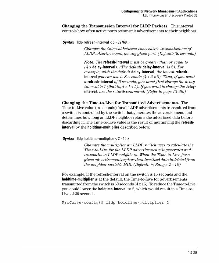
Changing the Transmission Interval for LLDP Packets. This interval controls how often active ports retransmit advertisements to their neighbors.
Changing the Time-to-Live for Transmitted Advertisements. The Time-to-Live value (in seconds) for all LLDP advertisements transmitted from a switch is controlled by the switch that generates the advertisement, and determines how long an LLDP neighbor retains the advertised data before discarding it. The Time-to-Live value is the result of multiplying the refresh-interval by the holdtime-multiplier described below.
For example, if the refresh-interval on the switch is 15 seconds and the holdtime-multiplier is at the default, the Time-to-Live for advertisements transmitted from the switch is 60 seconds (4 x 15). To reduce the Time-to-Live, you could lower the holdtime-interval to 2, which would result in a Time-to-Live of 30 seconds.
ProCurve(config)# lldp holdtime-multiplier 2
Syntax lldp refresh-interval < 5 - 32768 >
Changes the interval between consecutive transmissions of
LLDP advertisements on any given port. (Default: 30 seconds)
Note: The refresh-interval must be greater than or equal to
(4 x delay-interval). (The default delay-interval is 2). For
example, with the default delay-interval, the lowest refresh-interval you can use is 8 seconds (4 x 2 = 8). Thus, if you want
a refresh-interval of 5 seconds, you must first change the delay
interval to 1 (that is, 4 x 1 < 5). If you want to change the delay-interval, use the setmib command. (Refer to page 13-36.)
Syntax lldp holdtime-multiplier < 2 - 10 >
Changes the multiplier an LLDP switch uses to calculate the
Time-to-Live for the LLDP advertisements it generates and
transmits to LLDP neighbors. When the Time-to-Live for a
given advertisement expires the advertised data is deleted from
the neighbor switch’s MIB. (Default: 4; Range: 2 - 10)
13-35
Configuring for Network Management ApplicationsLLDP (Link-Layer Discovery Protocol)
Changing the Delay Interval Between Advertisements Generated by
Value or Status Changes to the LLDP MIB. The switch uses a delay-
interval setting to delay transmitting successive advertisements resulting from these LLDP MIB changes. If a switch is subject to frequent changes to its LLDP MIB, lengthening this interval can reduce the frequency of successive advertisements. The delay-interval can be changed using either an SNMP network management application or the CLI setmib command.
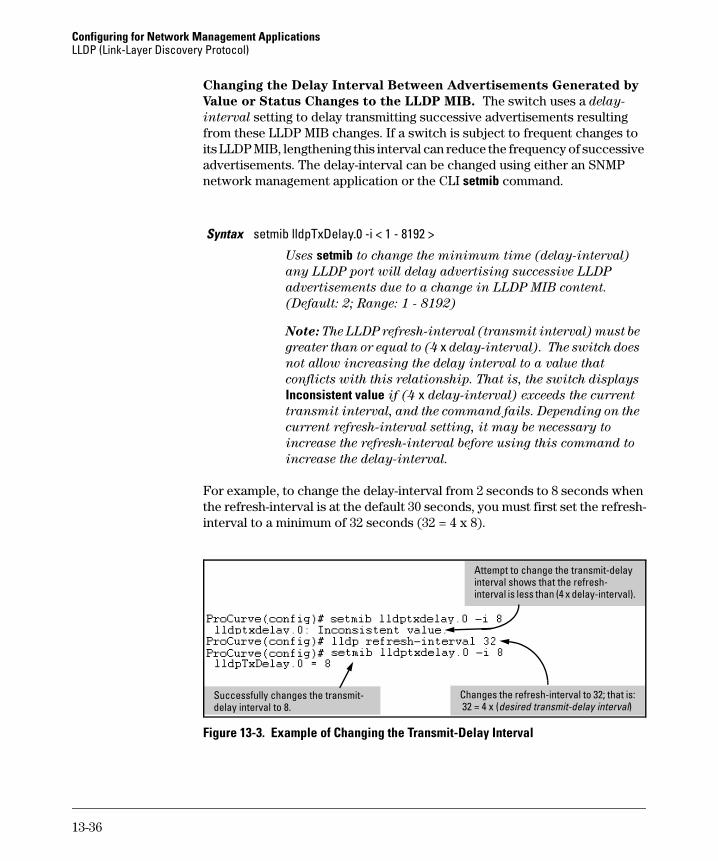
For example, to change the delay-interval from 2 seconds to 8 seconds when the refresh-interval is at the default 30 seconds, you must first set the refresh-interval to a minimum of 32 seconds (32 = 4 x 8).
Figure 13-3. Example of Changing the Transmit-Delay Interval
Syntax setmib lldpTxDelay.0 -i < 1 - 8192 >
Uses setmib to change the minimum time (delay-interval)
any LLDP port will delay advertising successive LLDP
advertisements due to a change in LLDP MIB content.
(Default: 2; Range: 1 - 8192)
Note: The LLDP refresh-interval (transmit interval) must be
greater than or equal to (4 x delay-interval). The switch does
not allow increasing the delay interval to a value that
conflicts with this relationship. That is, the switch displays
Inconsistent value if (4 x delay-interval) exceeds the current
transmit interval, and the command fails. Depending on the
current refresh-interval setting, it may be necessary to
increase the refresh-interval before using this command to
increase the delay-interval.
Attempt to change the transmit-delay interval shows that the refresh-interval is less than (4 x delay-interval).
Changes the refresh-interval to 32; that is: 32 = 4 x (desired transmit-delay interval)
Successfully changes the transmit-delay interval to 8.
13-36
Configuring for Network Management ApplicationsLLDP (Link-Layer Discovery Protocol)
Changing the Reinitialization Delay Interval. In the default configuration, a port receiving a disable command followed immediately by a txonly, rxonly, or tx_rx command delays reinitializing for two seconds, during which time LLDP operation remains disabled. If an active port is subjected to frequent toggling between the LLDP disabled and enabled states, LLDP advertisements are more frequently transmitted to the neighbor device. Also, the neighbor table in the adjacent device will change more frequently, as it deletes, then replaces LLDP data for the affected port which, in turn, generates SNMP traps (if trap receivers and SNMP notification are configured). All of this can unnecessarily increase network traffic. Extending the reinitialization-delay interval delays the port’s ability to reinitialize and generate LLDP traffic following an LLDP disable/enable cycle.
For example, the following command changes the reinitialization delay interval to five seconds:
ProCurve(config)# setmib lldpreinitdelay.0 -i 5
Configuring SNMP Notification Support
You can enable SNMP trap notification of LLDP data changes detected on advertisements received from neighbor devices, and control the interval between successive notifications of data changes on the same neighbor.
Enabling LLDP Data Change Notification for SNMP Trap Receivers.
Syntax setmib lldpReinitDelay.0 -i < 1 - 10 >
Uses setmib to change the minimum time (reinitialization
delay interval) an LLDP port will wait before reinitializing
after receiving an LLDP disable command followed closely by
a txonly or tx_rx command. The delay interval commences
with execution of the lldp admin-status < port-list > disable
Syntax [ no ] lldp enable-notification < port-list >
Enables or disables each port in < port-list > for sending
notification to configured SNMP trap receiver(s) if an LLDP
data change is detected in an advertisement received on the
port from an LLDP neighbor. (Default: Disabled)
For information on configuring trap receivers in the switch,
refer to the chapter titled “Configuring for Network
Management Applications” in the Management and
Configuration Guide for your switch.
13-37
Configuring for Network Management ApplicationsLLDP (Link-Layer Discovery Protocol)
For example, this command enables SNMP notification on ports 1 - 5:
ProCurve(config)# lldp enable-notification 1-5
Changing the Minimum Interval for Successive LLDP Data Change
Notifications for the Same Neighbor.
If LLDP trap notification is enabled on a port, a rapid succession of changes in LLDP information received in advertisements from one or more neighbors can generate a high number of traps. To reduce this effect, you can globally change the interval between successive notifications of neighbor data change.
For example, the following command limits change notification traps from a particular switch to one per minute.
Globally changes the interval between successive traps
generated by the switch. If multiple traps are generated in the
specified interval, only the first trap will be sent. The
remaining traps will be suppressed. (A network management
application can periodically check the switch MIB to detect any
missed change notification traps. Refer to IEEE 802.1AB-2005
or later for more information.) (Default: 5 seconds)
13-38
Configuring for Network Management ApplicationsLLDP (Link-Layer Discovery Protocol)
Configuring Per-Port LLDP Transmit and Receive Modes
These commands control LLDP advertisement traffic inbound and outbound on active ports.
Configuring LLDP Per-Port Advertisement Content
In the default LLDP configuration, outbound advertisements from each port on the switch include both the mandatory and the optional data listed in the next two subsections.
Mandatory Data. An active LLDP port on the switch always includes the mandatory data in its outbound advertisements. LLDP collects the mandatory data, and, except for the Remote Management Address, you cannot use LLDP commands to configure the actual data.
■ Chassis Type (TLV subelement)
■ Chassis ID (TLV)
■ Port Type (TLV subelement)
■ Port ID (TLV)
■ Remote Management Address (TLV; actual IP address is a subelement that can be a default address or a configured address)
Configuring a Remote Management Address for Outbound LLDP
Advertisements. This is an optional command you can use to include a specific IP address in the outbound LLDP advertisements for specific ports.
With LLDP enabled on the switch in the default LLDP
configuration, each port is configured to transmit and receive
LLDP packets. These options enable you to control which ports
participate in LLDP traffic and whether the participating
ports allow LLDP traffic in only one direction or in both
directions.
txonly: Configures the specified port(s) to transmit LLDP pack-
ets, but block inbound LLDP packets from neighbor devices.
rxonly: Configures the specified port(s) to receive LLDP packets
from neighbors, but block outbound packets to neighbors.
tx_rx: Configures the specified port(s) to both transmit and
receive LLDP packets. (This is the default setting.)
disable: Disables LLDP packet transmit and receive on the
specified port(s).
13-39
Configuring for Network Management ApplicationsLLDP (Link-Layer Discovery Protocol)
For example, if port 3 belongs to a subnetted VLAN that includes a secondary IP address of 10.10.10.100 and you wanted port 3 to use this secondary address in LLDP advertisements, you would need to execute the following command:
Optional Data. You can configure an individual port or group of ports to exclude one or more of these data types from outbound LLDP advertisements. Note that optional data types, when enabled, are populated with data internal to the switch; that is, you cannot use LLDP commands to configure their actual content.
Replaces the default IP address for the port with an IP
address you specify. This can be any IP address configured
in a static VLAN on the switch, even if the port does not
belong to the VLAN configured with the selected IP address.
The no form of the command deletes the specified IP
address. If there are no IP addresses configured as
management addresses, then the IP address selection
method returns to the default operation. (Default: The port
advertises the primary IP address of the lowest-numbered
VLAN (VID) to which it belongs. If there is no IP address
configured on the VLAN(s) to which the port belongs, and
the port is not configured to advertise an IP address from
any other (static) VLAN on the switch, then the port
advertises an address of 127.0.0.1.)
Note: This command does not accept either IP addresses
acquired through DHCP or Bootp, or IP addresses that are
not configured in a static VLAN on the switch
13-40
Configuring for Network Management ApplicationsLLDP (Link-Layer Discovery Protocol)
For example, if you wanted to exclude the system name from the outbound LLDP advertisements for all ports on a 2626 switch, you would use this command:
ProCurve(config)# no lldp config 1-26 basicTlvEnable system_name
If you later decided to reinstate the system name on ports 1-5, you would use this command:
For outbound LLDP advertisements, includes the system’s
assigned name.
system_descr
For outbound LLDP advertisements, includes an
alphanumeric string describing the full name and version
identification for the system’s hardware type, software
version, and networking application.
system_cap
For outbound advertisements, includes a bitmask of
system capabilities (device functions) that are supported.
Also includes information on whether the capabilities are
enabled.
Command Page
show lldp info local-device below
show lldp info remote-device 13-43
show lldp info stats 13-46
13-41
Configuring for Network Management ApplicationsLLDP (Link-Layer Discovery Protocol)
Displaying Switch Information Available for Outbound Advertisements
These commands display the current switch information that will be used to populate outbound LLDP advertisements.
For example, in the default configuration, the switch information currently available for outbound LLDP advertisements appears similar to the display in figure 13-4 on page page 13-43.
Syntax show lldp info local-device [ port-list ]
Without the [ port-list ] option, this command displays the global
switch information and the per-port information currently
available for populating outbound LLDP advertisements.
With the [ port-list ] option, this command displays only the
following port-specific information that is currently available
for outbound LLDP advertisements on the specified ports:
• PortType• PortId• PortDesc
Note: This command displays the information available on
the switch. Use the lldp config < port-list > command to change
the selection of information that is included in actual
outbound advertisements. In the default LLDP configuration,
all information displayed by this command is transmitted in
outbound advertisements.
13-42
Configuring for Network Management ApplicationsLLDP (Link-Layer Discovery Protocol)
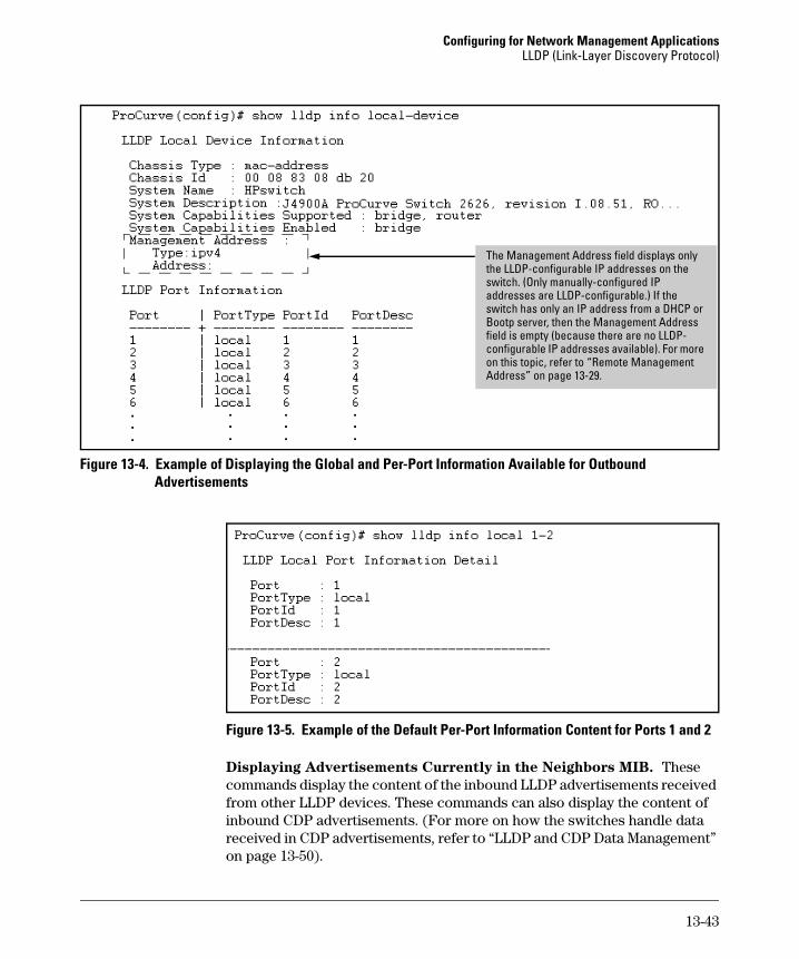
Figure 13-4. Example of Displaying the Global and Per-Port Information Available for Outbound Advertisements
Figure 13-5. Example of the Default Per-Port Information Content for Ports 1 and 2
Displaying Advertisements Currently in the Neighbors MIB. These commands display the content of the inbound LLDP advertisements received from other LLDP devices. These commands can also display the content of inbound CDP advertisements. (For more on how the switches handle data received in CDP advertisements, refer to “LLDP and CDP Data Management” on page 13-50).
The Management Address field displays only the LLDP-configurable IP addresses on the switch. (Only manually-configured IP addresses are LLDP-configurable.) If the switch has only an IP address from a DHCP or Bootp server, then the Management Address field is empty (because there are no LLDP-configurable IP addresses available). For more on this topic, refer to “Remote Management Address” on page 13-29.
13-43
Configuring for Network Management ApplicationsLLDP (Link-Layer Discovery Protocol)
Syntax show lldp info remote-device [ port-list ]
Without the [ port-list ] option, this command provides a global
list of the individual devices it has detected by reading LLDP
advertisements (and also CDP advertisements). Discovered
devices are listed by the inbound port on which they were
discovered.
Multiple devices listed for a single port indicates either or both
of the following:
– A discovered device is transmitting both LLDP and CDP
packets with different chassis and port ID information.
– Multiple devices are connected to the switch through a hub.
Discovering the same device on multiple ports indicates that
the remote device may be connected to the switch in one of the
following ways:
– Through different VLANS using separate links. (This
applies to switches that use the same MAC address for all
configured VLANs.)
– Through different links in the same trunk.
– Through different links using the same VLAN. (In this
case, spanning-tree should be invoked to prevent a net-
work topology loop. Note that LLDP packets travel on links
that spanning-tree blocks for other traffic types.)
With the [ port-list ] option, this command provides a listing of
the LLDP data that the switch has detected in advertisements
received on the specified ports. If neighbor data is read from
CDP advertisements, the switch remaps this information into
the switch’s LLDP neighbors MIB in addition to the CDP
Neighbors MIB.
For descriptions of the various types of information displayed
by these commands, refer to Table 13-10 on page 13-28.
13-44
Configuring for Network Management ApplicationsLLDP (Link-Layer Discovery Protocol)
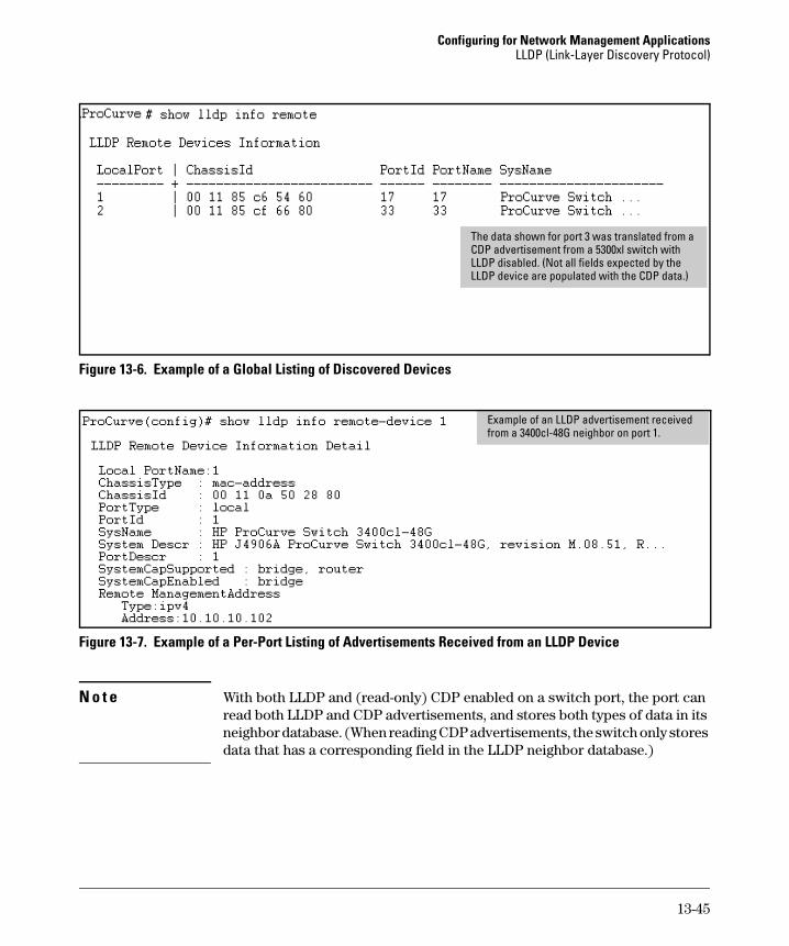
Figure 13-6. Example of a Global Listing of Discovered Devices
Figure 13-7. Example of a Per-Port Listing of Advertisements Received from an LLDP Device
N o t e With both LLDP and (read-only) CDP enabled on a switch port, the port can read both LLDP and CDP advertisements, and stores both types of data in its neighbor database. (When reading CDP advertisements, the switch only stores data that has a corresponding field in the LLDP neighbor database.)
The data shown for port 3 was translated from a CDP advertisement from a 5300xl switch with LLDP disabled. (Not all fields expected by the LLDP device are populated with the CDP data.)
Example of an LLDP advertisement received from a 3400cl-48G neighbor on port 1.
13-45
Configuring for Network Management ApplicationsLLDP (Link-Layer Discovery Protocol)
Displaying LLDP Statistics
LLDP statistics are available on both a global and a per-port levels. Rebooting the switch resets the LLDP statistics counters to zero. Disabling the transmit and/or receive capability on a port “freezes” the related port counters at their current values.
Syntax show lldp info stats [ port-list ]
The global LLDP statistics command displays an overview of
neighbor detection activity on the switch, plus data on the
number of frames sent, received, and discarded per-port. The
per-port LLDP statistics command enhances the list of per-port
statistics provided by the global statistics command with some
additional per-port LLDP statistics.
Global LLDP Counters:
Neighbor Entries List Last Updated: Shows the elapsed time since
a neighbor was last added or deleted.
New Neighbor Entries Count: Shows the total of new LLDP
neighbors detected since the last switch reboot. Disconnecting,
then reconnecting a neighbor increments this counter.
Neighbor Entries Deleted Count: Shows the number of neighbor
deletions from the MIB for AgeOut Count and forced drops for
all ports. For example, if the admin status for port on a
neighbor device changes from tx_rx or txonly to disabled or
rxonly, then the neighbor device sends a “shutdown” packet out
the port and ceases transmitting LLDP frames out that port.
The device receiving the shutdown packet deletes all
information about the neighbor received on the applicable
inbound port and increments the counter .
Neighbor Entries Dropped Count: Shows the number of valid LLDP
neighbors the switch detected, but could not add. This can
occur, for example, when a new neighbor is detected when the
switch is already supporting the maximum number of
neighbors. Refer to “Neighbor Maximum” on page 13-49.
Neighbor Entries AgeOut Count: Shows the number of LLDP
neighbors dropped on all ports due to Time-to-Live expiring.
— Continued on the next page. —
13-46
Configuring for Network Management ApplicationsLLDP (Link-Layer Discovery Protocol)
— Continued from the preceding page. —
Per-Port LLDP Counters:
NumFramesRecvd: Shows the total number of valid, inbound
LLDP advertisements received from any neighbor(s) on < port-list >. Where multiple neighbors are connected to a port through
a hub, this value is the total number of LLDP advertisements
received from all sources.
NumFramesSent: Shows the total number of LLDP
advertisements sent from < port-list >.
NumFramesDiscarded: Shows the total number of inbound LLDP
advertisements discarded by < port-list >. This can occur, for
example, when a new neighbor is detected on the port, but the
switch is already supporting the maximum number of
neighbors. Refer to “Neighbor Maximum” on page 13-49. This
can also be an indication of advertisement formatting
problems in the neighbor device.
Frames Invalid: Shows the total number of invalid LLDP
advertisements received on the port. An invalid advertisement
can be caused by header formatting problems in the neighbor
device.
TLVs Unrecognized: Shows the total number of LLDP TLVs
received on a port with a type value in the reserved range. This
could be caused by a basic management TLV from a later LLDP
version than the one currently running on the switch.
TLVs Discarded: Shows the total number of LLDP TLVs discarded
for any reason. In this case, the advertisement carrying the
TLV may be accepted, but the individual TLV was not usable.
Neighbor Ageouts: Shows the number of LLDP neighbors
dropped on the port due to Time-to-Live expiring.
13-47
Configuring for Network Management ApplicationsLLDP (Link-Layer Discovery Protocol)
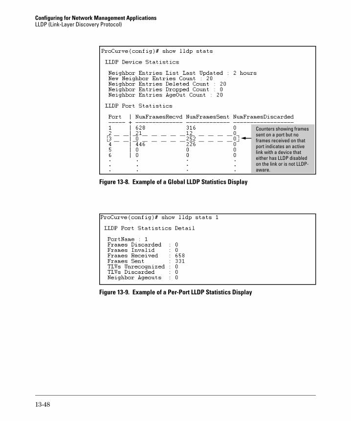
Figure 13-8. Example of a Global LLDP Statistics Display
Figure 13-9. Example of a Per-Port LLDP Statistics Display
Counters showing frames sent on a port but no frames received on that port indicates an active link with a device that either has LLDP disabled on the link or is not LLDP-aware.
13-48
Configuring for Network Management ApplicationsLLDP (Link-Layer Discovery Protocol)
LLDP Operating Notes
Neighbor Maximum. The neighbors table in the switch supports as many neighbors as there are ports on the switch. The switch can support multiple neighbors connected through a hub on a given port, but if the switch neighbor maximum is reached, advertisements from additional neighbors on the same or other ports will not be stored in the neighbors table unless some existing neighbors time-out or are removed.
LLDP Packet Forwarding: If CDP is globally disabled on a switch, the switch forwards CDP packets received from a neighbor CDP device instead of reading and dropping them. However, an 802.1D-compliant switch does not forward LLDP packets, regardless of whether LLDP is globally enabled or disabled on the switch.
One IP Address Advertisement Per-Port: LLDP advertises only one IP address per-port, even if multiple IP addresses are configured by lldp config < port-list > ipAddrEnable on a given port.
802.1Q VLAN Information. LLDP packets do not include 802.1Q header information, and are always handled as untagged packets.
Effect of 802.1X Operation. If 802.1X port security is enabled on a port and a connected device is not authorized, LLDP packets are not transmitted or received on that port. Any neighbor data stored in the neighbor MIB for that port prior to the unauthorized device connection remains in the MIB until it ages out. If an unauthorized device later becomes authorized, LLDP transmit and receive operation resumes.
Neighbor Data Can Remain in the Neighbor Database After the
Neighbor Is Disconnected. After disconnecting a neighbor LLDP device from the switch, the neighbor can continue to appear in the switch’s neighbor database for an extended period if the neighbor’s holdtime-multiplier is high; especially if the refresh-interval is large. Refer to “Changing the Time-to-Live for Transmitted Advertisements” on page 13-35.
13-49
Configuring for Network Management ApplicationsLLDP (Link-Layer Discovery Protocol)
LLDP and CDP Data Management
This section describes points to note regarding LLDP (Link-Layer Discovery Protocol) and CDP (Cisco Discovery Protocol) data received by the switch from other devices. LLDP operation includes both transmitting LLDP packets to neighbor devices and reading LLDP packets received from neighbor devices. CDP operation is limited to reading incoming CDP packets from neighbor devices. (ProCurve switches do not generate CDP packets.)
LLDP and CDP Neighbor Data
With both LLDP and (read-only) CDP enabled on a switch port, the port can read both LLDP and CDP advertisements, and stores the data from both types of advertisements in its neighbor database. (The switch only stores CDP data that has a corresponding field in the LLDP neighbor database.) The neighbor database itself can be read by either LLDP or CDP methods or by using the show lldp commands. Take note of the following rules and conditions:
■ If the switch receives both LLDP and CDP advertisements on the same port from the same neighbor the switch stores this information as two separate entries if the advertisements have differences chassis ID and port ID information.
■ If the chassis and port ID information are the same, the switch stores this information as a single entry. That is, LLDP data overwrites the corre-sponding CDP data in the neighbor database if the chassis and port ID information in the LLDP and CDP advertisements received from the same device is the same.
■ Data read from a CDP packet does not support some LLDP fields, such as “System Descr”, “SystemCapSupported”, and “ChassisType”. For such fields, LLDP assigns relevant default values. Also:
• The LLDP “System Descr” field maps to CDP’s “Version” and “Plat-form” fields.
• The switch assigns “ChassisType” and “PortType” fields as “local” for both the LLDP and the CDP advertisements it receives.
• Both LLDP and CDP support the “System Capability” TLV. However, LLDP differentiates between what a device is capable of supporting and what it is actually supporting, and separates the two types of information into subelements of the System Capability TLV. CDP has only a single field for this data. Thus, when CDP System Capability data is mapped to LLDP, the same value appears in both LLDP System Capability fields.
• System Name and Port Descr are not communicated by CDP, and thus are not included in the switch’s Neighbors database.
13-50
Configuring for Network Management ApplicationsLLDP (Link-Layer Discovery Protocol)
N o t e Because ProCurve switches do not generate CDP packets, they are not represented in the CDP data collected by any neighbor devices running CDP.
A switch with CDP disabled forwards the CDP packets it receives from other devices, but does not store the CDP information from these packets in its own MIB.
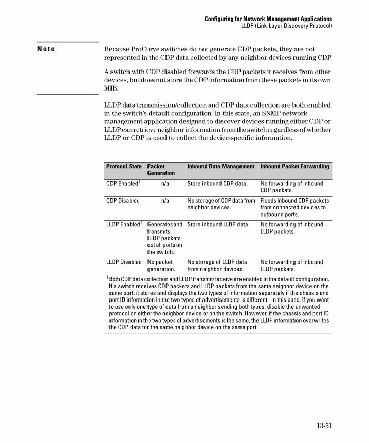
LLDP data transmission/collection and CDP data collection are both enabled in the switch’s default configuration. In this state, an SNMP network management application designed to discover devices running either CDP or LLDP can retrieve neighbor information from the switch regardless of whether LLDP or CDP is used to collect the device-specific information.
Protocol State Packet Generation
Inbound Data Management Inbound Packet Forwarding
CDP Enabled1 n/a Store inbound CDP data. No forwarding of inbound CDP packets.
CDP Disabled n/a No storage of CDP data from neighbor devices.
Floods inbound CDP packets from connected devices to outbound ports.
LLDP Enabled1 Generates and transmits LLDP packets out all ports on the switch.
Store inbound LLDP data. No forwarding of inbound LLDP packets.
LLDP Disabled No packet generation.
No storage of LLDP data from neighbor devices.
No forwarding of inbound LLDP packets.
1Both CDP data collection and LLDP transmit/receive are enabled in the default configuration. If a switch receives CDP packets and LLDP packets from the same neighbor device on the same port, it stores and displays the two types of information separately if the chassis and port ID information in the two types of advertisements is different. In this case, if you want to use only one type of data from a neighbor sending both types, disable the unwanted protocol on either the neighbor device or on the switch. However, if the chassis and port ID information in the two types of advertisements is the same, the LLDP information overwrites the CDP data for the same neighbor device on the same port.
13-51
Configuring for Network Management ApplicationsLLDP (Link-Layer Discovery Protocol)
CDP Operation and Commands
By default the switches covered by this guide have CDP enabled on each port. This is a read-only capability, meaning that the switch can receive and store information about adjacent CDP devices but does not generate CDP packets.
When a CDP-enabled switch receives a CDP packet from another CDP device, it enters that device’s data in the CDP Neighbors table, along with the port number where the data was received (and does not forward the packet). The switch also periodically purges the table of any entries that have expired. (The hold time for any data entry in the switch’s CDP Neighbors table is configured in the device transmitting the CDP packet, and cannot be controlled in the switch receiving the packet.) A switch reviews the list of CDP neighbor entries every three seconds, and purges any expired entries.
N o t e For details on how to use an SNMP utility to retrieve information from the switch’s CDP Neighbors table maintained in the switch’s MIB (Management Information Base), refer to the documentation provided with the particular SNMP utility.
Viewing the Switch’s Current CDP Configuration. CDP is shown as enabled/disabled both globally on the switch and on a per-port basis.
Command Page
show cdp 13-52
show cdp neighbors [< port-list > detail][detail < port-list >]
13-53
[no] cdp run 13-54
[no] cdp enable < port-list > 13-54
Syntax: show cdp
Lists the switch’s global and per-port CDP configuration.
13-52
Configuring for Network Management ApplicationsLLDP (Link-Layer Discovery Protocol)
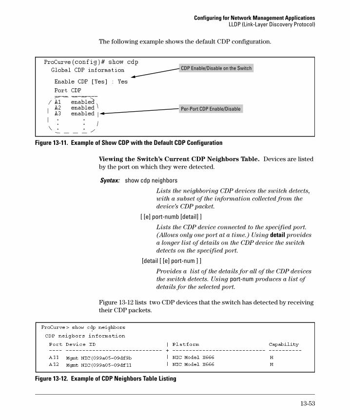
The following example shows the default CDP configuration.
Figure 13-11. Example of Show CDP with the Default CDP Configuration
Viewing the Switch’s Current CDP Neighbors Table. Devices are listed by the port on which they were detected.
Figure 13-12 lists two CDP devices that the switch has detected by receiving their CDP packets.
Figure 13-12. Example of CDP Neighbors Table Listing
CDP Enable/Disable on the Switch
Per-Port CDP Enable/Disable
Syntax: show cdp neighbors
Lists the neighboring CDP devices the switch detects,
with a subset of the information collected from the
device’s CDP packet.
[ [e] port-numb [detail] ]
Lists the CDP device connected to the specified port.
(Allows only one port at a time.) Using detail provides
a longer list of details on the CDP device the switch
detects on the specified port.
[detail [ [e] port-num ] ]
Provides a list of the details for all of the CDP devices
the switch detects. Using port-num produces a list of
details for the selected port.
13-53
Configuring for Network Management ApplicationsLLDP (Link-Layer Discovery Protocol)
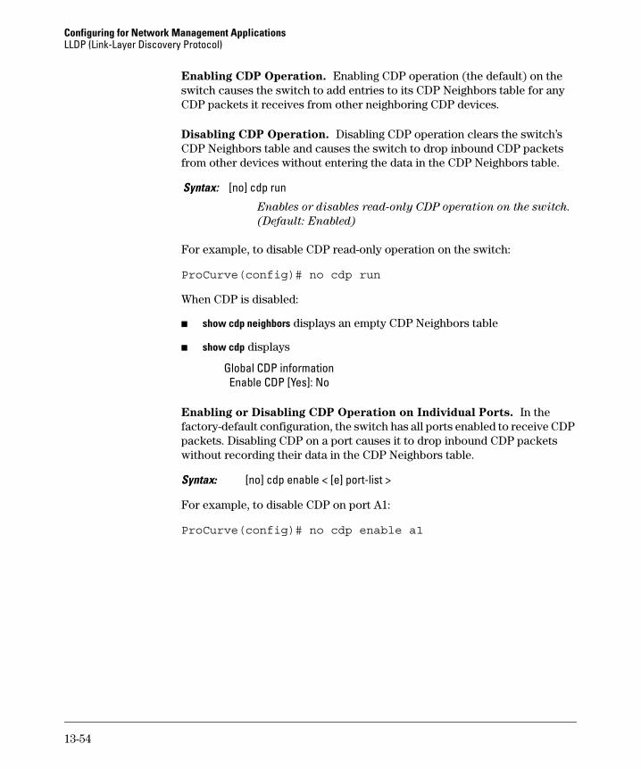
Enabling CDP Operation. Enabling CDP operation (the default) on the switch causes the switch to add entries to its CDP Neighbors table for any CDP packets it receives from other neighboring CDP devices.
Disabling CDP Operation. Disabling CDP operation clears the switch’s CDP Neighbors table and causes the switch to drop inbound CDP packets from other devices without entering the data in the CDP Neighbors table.
For example, to disable CDP read-only operation on the switch:
ProCurve(config)# no cdp run
When CDP is disabled:
■ show cdp neighbors displays an empty CDP Neighbors table
■ show cdp displays
Global CDP information Enable CDP [Yes]: No
Enabling or Disabling CDP Operation on Individual Ports. In the factory-default configuration, the switch has all ports enabled to receive CDP packets. Disabling CDP on a port causes it to drop inbound CDP packets without recording their data in the CDP Neighbors table.
Syntax: [no] cdp enable < [e] port-list >
For example, to disable CDP on port A1:
ProCurve(config)# no cdp enable a1
Syntax: [no] cdp run
Enables or disables read-only CDP operation on the switch.