Configuring Load Balancing and DynamicChannel Change (DCC) on the Cisco CMTS
OL-3787-06November 2006
The Load Balancing feature for the Cisco Cable Modem Termination System (CMTS) allows systemoperators to distribute cable modems across radio frequency (RF) downstream and upstream channelson the same cable interface line card. Load balancing maximizes bandwidth and usage of the cable plant.
Effective with Cisco IOS Release 12.3(17a)BC, and later 12.3 BC releases, load balancing is furtherenhanced and supported with Dynamic Channel Change (DCC). This document describes allimplementations of load balancing on the Cisco CMTS, dependent upon the IOS release installed.
Feature Specifications for Load Balancing on the Cisco CMTS
Finding Support Information for Platforms and Cisco IOS Software Images
Use Cisco Feature Navigator to find information about platform support and Cisco IOS software imagesupport. Access Cisco Feature Navigator athttp://www.cisco.com/go/fn. You must have an account onCisco.com. If you do not have an account or have forgotten your username or password, clickCancelatthe login dialog box and follow the instructions that appear.
Feature HistoryRelease Modification
Release 12.2(15)BC1 This feature was introduced for Cisco uBR7246VXR and Cisco uBR10012routers.
Release 12.3(9a)BC This feature was introduced for the Cisco uBR7100 Series universalbroadband routers.
Release 12.3(17a)BC Dynamic Channel Change (DCC) for Load Balancing supported on theCisco uBR10012 and Cisco uBR7246VXR routers.
Release 12.3(17b)BC4 Downstream load balancing further enhanced to equalize downstream loadbalancing with upstream load balancing group members. This enhancementsynchronizes thepending statistic between different cable interface linecards in the load balancing group. Refer to the“Downstream Load BalancingDistribution with Upstream Load Balancing” section on page 11.
Configuring Load Balancing and Dynamic Channel Change (DCC) on the Cisco CMTS Contents
2Cisco IOS Release 12.3 BC
OL-3787-05
Contents• Prerequisites, page 2
• Restrictions, page 3
• Information on the Load Balancing on the Cisco CMTS Feature, page 5
• How to Configure Load Balancing on the Cisco CMTS, page 13
• Configuration Examples for Load Balancing on the Cisco CMTS, page 28
• How to Configure Dynamic Channel Change for Load Balancing, page 32
• Configuration Examples of Dynamic Channel Change (DCC) for Load Balancing, page 35
• System Error Messages for Load Balancing, page 37
• Additional References, page 38
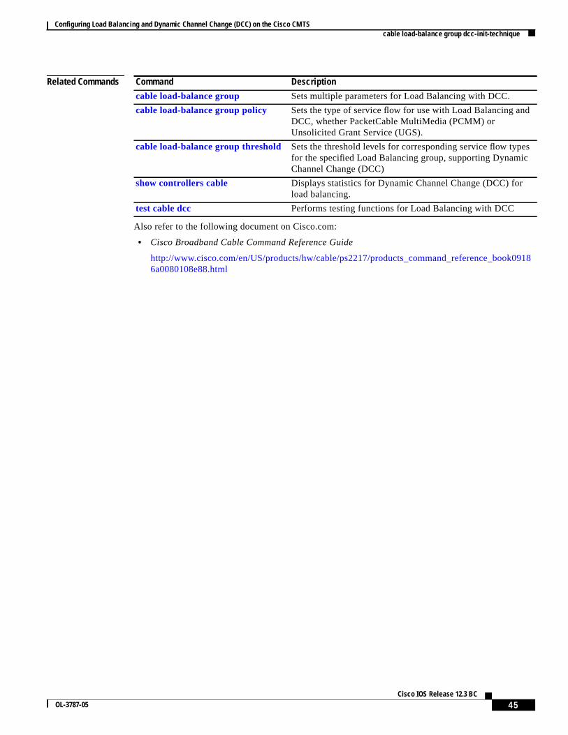
• Command Reference, page 41
• Glossary, page 55
Prerequisites
Prerequisites for Load Balancing on the Cisco CMTSThe Load Balancing on the Cisco CMTS feature has the following prerequisites:
• The Cisco uBR7200 series and Cisco uBR10012 router must be running Cisco IOSRelease 12.2(15)BC1 or later Cisco IOS Release 12.2 BC release.
• Load balancing can be done only on upstreams and downstreams that share physical connectivitywith the same group of cable modems.
• When performing load balancing among downstreams, you must also configure the knowndownstream center frequency to be used on each downstream interface, using thecabledownstream frequencycommand. (This is an informational-only configuration on cable interfacesthat use an external upconverter, but it is still required for load balancing so that the Cisco CMTSknows what frequencies it should use when moving cable modems from one downstream to another.)
Prerequisites for Dynamic Channel Change for Load Balancing• DCC can be done only to a cable modem that is physically connected to both source and target
upstream or downstream channels, or both.
• Upstreams and downstream channels that share the same physical connectivity must have differentcenter frequencies separated by channel-width.
• The difference between the physical layer parameters on the source and target DCC channels mustbe within the threshold required by the desired DCC initialization technique.
• DOCSIS1.1 must be enabled for a modem to behave properly for the DCC operation. Note that notall DOCSIS1.1 certified modems are DCC capable as the CableLabs DCC ATP tests needenhancement for complete coverage.
Configuring Load Balancing and Dynamic Channel Change (DCC) on the Cisco CMTS Restrictions
3Cisco IOS Release 12.3 BC
OL-3787-05
Restrictions
Restrictions for Load Balancing on the Cisco CMTSThe Load Balancing on the Cisco CMTS feature has the following restrictions:
• For additional information about support of Load Balancing on the Cisco CMTS, refer toFeatureSpecifications for Load Balancing on the Cisco CMTS.
• Load balancing can be done only on a per chassis basis—all interfaces in a load-balance group mustbe provided by the same chassis.
• A downstream or upstream can belong to only one load-balance group.
• All downstreams and upstreams in a load-balance group must share physical connectivity to thesame group of cable modems. Downstreams can be in a separate load-balance group than upstreams,but all downstreams or all upstreams that have the same RF physical connectivity must be membersof the same load-balance group.
• You can configure only one load-balance group per shared physical domain (upstream or interface).You cannot configure multiple load-balance groups to distribute downstreams or upstreams thatshare physical connectivity.
• In later Cisco IOS Releases, such as release 12.3(17a)BC, you can create a maximum of 80load-balance groups on each chassis (the older limitation was 20). However, in prior Cisco IOSreleases, you can reuse those load-balance groups on different sets of cable interfaces, as long asthey are in different domains. If downstream channels are not included in a load-balance group, theneach downstream channel can be considered a separate domain.
• If an upstream port is operational, using theno shutdowncommand, and is not being used and notconnected, load balancing attempts to use the port even though there are no cable modems registeredon that port. When the upstream port is up, it is put into INIT state and load balancing includes thisport as a potential target. However, if the load balancing sees multiple failures moving to thisupstream, it is set to DISABLE state and the port is avoided later on in load balancing processes.
• The load-balancing algorithms assume a relatively even distribution of usage among modems. In thesituation where one cable modem creates the bulk of the load on an interface, the load-balancingthresholds should be configured for a value above the load created by that single modem.
• Load balancing is done on cable modems in real-time, using current load-usage statistics. Youcannot perform load balancing according to the time-of-day or using a schedule.
• You cannot select particular cable modems to be automatically moved for load balancing, althoughyou can exclude cable modems from load balancing operations altogether on the basis of their MACaddress or organization unique identifier (OUI). (You can use thetest cable load-balancecommandto manually move a particular cable modem among upstreams, but this is done typically to test theconfiguration of the load balance groups.)
• If you have configured upstream shared spectrum groups while doing downstream load balancing,the downstream in each MAC domain must not use overlapping upstream groups. For example, thedownstream in one MAC domain could use an upstream spectrum band of 10 to 30 MHz, while thedownstream in a second MAC domain could use an upstream spectrum band of 30 to 42 MHz. EachMAC domain has its own upstream shared spectrum group, allowing the load-balance group tocontain the downstreams for both MAC domains.
Note A MAC domain is one downstream and its associated upstreams.
Configuring Load Balancing and Dynamic Channel Change (DCC) on the Cisco CMTS Restrictions
4Cisco IOS Release 12.3 BC
OL-3787-05
• All upstream ports coming from the same splitter must be using different center frequencies that areseparated by the channel width. For example, if the upstreams are using a channel width of 3.2 MHz,the center frequencies for all upstreams must be separated by at least 3.2 MHz.
• In Cisco IOS Release 12.2(15)BC1, the dynamic load balancing method uses the DownstreamFrequency Override message to move cable modems between downstream channels, which resultsin cable modems going offline and having to reregister, resulting in a short, temporary loss ofconnectivity for the customer. This is because the DOCSIS 1.0 specification requires cable modemsto reregister whenever the downstream is changed using the Downstream Frequency Overridemessage. Cable modems should not go offline when they are moved between upstreams. Thisbehavior is modified in Cisco IOS Release 12.3(17a)BC, with the introduction of four initializationtechniques for Dynamic Channel Change (DCC). See the“Configuring DCC for Load Balancing onthe Cisco CMTS” section on page 33.
• As required by cable interface bundling, all interfaces in a load-balance group must also be in thesame HCCP interface bundle.
• If you have configured load balancing, the provisioning system must not assign specific upstreamchannels or downstream frequencies to individual cable modems in their DOCSIS configurationfiles. Any cable modems require specific upstream channels or downstream frequencies must beexcluded from load-balancing operations (using thecable load-balance exclude command).
• Do not use the utilization method of load balancing on cable interfaces that have a small number ofcable modems and where a single modem is responsible for the majority of the interface load. In thiscondition, the Cisco CMTS could end up continually moving cable modems from one interface toanother in an endless attempt to load balance the interfaces. To avoid this, configure the utilizationthreshold to a value that is higher than what can be caused by any single cable modem.
• In Cisco IOS Release 12.2(15)BC1, you should not configure an interface for both dynamic loadbalancing and Hot-Standby Connection-to-Connection (HCCP) N+1 redundancy, because cablemodems will go offline after a switchover. You can configure the interface for HCCP N+1redundancy when you are using only static and passive load balancing.
Load balancing, however, does not continue after a switchover from a Working to a Protect interface.Load balancing resumes when the Cisco CMTS switches back to the Working interface. (Onepossible workaround is to pre-configure the Protect interface with the appropriate load-balancingcommands, but you must be certain that the downstreams and upstreams in each load-balance groupafter the switchover have the same physical connectivity.)
Restrictions for Dynamic Channel Change for Load Balancing• DCC initialization 0 is the default technique for load balancing DCC. Legacy line cards can only
use DCC initialization technique 0.
• DCC initialization techniques 1 to 4 are strictly for downstream channel changes within the samecable interface line card, or intra-card, implementation, and cannot be used for Load Balancingbetween multiple cable interface line cards in inter-card implementation.
• For Load Balancing between multiple cable interface line cards (inter-card implementation), DCCinitialization technique 0 is to be used in all cases, regardless of what technique is set for the loadbalancing group or which cable interface line card types are used.
• The source and target upstreams and downstreams must share physical connectivity with the modemdesired for a DCC transaction.
• Independent downstream change is not supported, and cross-MAC domain upstream changes mustoccur with the associated downstream changes.
Configuring Load Balancing and Dynamic Channel Change (DCC) on the Cisco CMTS Restrictions
5Cisco IOS Release 12.3 BC
OL-3787-05
• The source and target downstream interfaces must belong to the same virtual bundle, and the sameload balancing group if DCC is used for load balancing.
• For DCC initialization techniques 1 to 4, all the configuration variables of the cable modem mustremain constant with the exception of the configuration variables which are explicitly changed bythe DCC-REQ messages encodings.
• DCC initialization techniques 2 to 4 must not be used if the propagation delay differences betweenthe old and new channels exceeds the ranging accuracy requirement defined in DOCSIS, i.e. 0.25usec plus symbol time.
For example, for a symbol rate of 1.28Msps, the timing offset difference between the source andtarget upstream channel is floor[(0.250 us + 0.5*0.781us)/(1/10.24)] = 6.
• The attenuation or frequency response differences between the old and new upstream channelscauses the received power at the CMTS to change by more than 6dB.
• DCC initialization technique 3 must not be used if the conditions for using technique 2 is not met.
• DCC initialization technique 4 must not be used if the conditions for using technique 2 cannot bemet.
• Micro-reflections on the new upstream channel result in an unacceptable BER (greater than 1e-8)with pre-equalization coefficients set to the initial setting.
• DCC is only used for dynamic downstream load balancing on DOCSIS1.1 modems. UCC is usedfor dynamic upstream load balancing. DCC is not used for static load balancing.
• Prolonged interruption of the multicast traffic is expected if the cable modem moved by DCC is thefirst one in a dynamic multicast group on the target interface. The downstream multicast service flowcannot be reestablished until the CMTS receives an IGMP join message from the CPE as the resultof the CMTS IGMP query, where the IGMP query interval is set to 1 minute. This is a IGMPv2limitation.
DCC Restrictions with N+1 Redundancy and Inter-card Load Balancing
• Inter-card Load Balancing is not supported with cable interface line cards using N+1 Redundancy.Refer to general DCC restrictions for additional information.
• Dynamic load balancing should not be used together with N+1 redundancy. Modems withoutstanding DCC transactions go offline after a switchover event.
Note When cable modems go offline during switchover event, this prompts the load balancing feature toengage. Cable modems move in relation to the switchover event. When the cable modems return online,load balancing may need to initiate again.
To facilitate load balancing during a switchover, you may increase the dynamic load balance threshold,in the case that the system has a given percentage of cable modems that reset during switchover. Analternate method is to use static load balancing with N+1 Redundancy. Refer to the“Types ofLoad-Balancing Operations” section on page 6 for additional information.
Configuring Load Balancing and Dynamic Channel Change (DCC) on the Cisco CMTS Information on the Load Balancing on the Cisco CMTS Feature
6Cisco IOS Release 12.3 BC
OL-3787-05
Information on the Load Balancing on the Cisco CMTS FeatureThis section describes the operation, concepts, and benefits of the Load Balancing on the Cisco CMTSfeature.
• Feature Overview, page 6
• Benefits, page 13
Feature OverviewThis Load Balancing on the Cisco CMTS feature allows service providers to optimally use bothdownstream and upstream bandwidth, enabling the deployment of new, high-speed services such asvoice and video services. This feature also can help reduce network congestion due to the unevendistribution of cable modems across the cable network and due to different usage patterns of individualcustomers.
By default, the Cisco CMTS platforms use a form of load balancing that attempts to equally distributethe cable modems to different upstreams when the cable modems register. You can refine this form ofload balancing by imposing a limit on the number of cable modems that can register on any particularupstream, using thecable upstream admission-control command.
However, this default form of load balancing affects the cable modems only when they initially registerwith the Cisco CMTS. It does not dynamically rebalance the cable modems at later times, such as whenthey might change upstream channels in response to RF noise problems, or when bandwidth conditionschange rapidly because of real-time traffic such as Voice over IP (VoIP) and video services. It also doesnot affect how the cable modems are distributed among downstream channels.
Types of Load-Balancing Operations
The Load Balancing on the Cisco CMTS feature provides a more comprehensive load-balancing solutionby adding new forms of registration-based and dynamic load balancing. In Cisco IOS Release12.2(15)BC1, the Load Balancing on the Cisco CMTS feature supports the following configurable typesof load balancing:
• Static Load Balancing—This is a form of registration-based load balancing that is done at the timea cable modem registers. When a cable modem sends its registration request (REG-REQ) andranging request (RNG-REQ) messages, the Cisco CMTS responds with a ranging response(RNG-RSP) message that includes either a Downstream Frequency Override or an UpstreamChannel ID Override field that instructs the cable modem which channels it should use.
• Passive Load Balancing—This is a form of registration-based load balancing that can be configuredfor individual cable modems. In this mode, the Cisco CMTS does not need to send any type ofmessaging to the modem. The Cisco CMTS ignores the RNG-REQ message from a cable modemthat is attempting to register using a downstream or upstream that is currently overloaded. The cablemodem repeats its registration request until it reaches a channel that can accept additional modems.
Note By default, the Cisco CMTS uses static load balancing, but passive load balancing can bespecified for individual older cable modems (using thecable load-balance excludecommand) that do not respond well to the static form. This method should be used only asneeded because when used for a large number of modems, it could generate a large volumeof ranging retry messages.
Configuring Load Balancing and Dynamic Channel Change (DCC) on the Cisco CMTS Information on the Load Balancing on the Cisco CMTS Feature
7Cisco IOS Release 12.3 BC
OL-3787-05
• Dynamic load balancing—This is a form of load balancing in which cable modems are movedamong upstreams and downstreams after their initial registration and they come online, whilepotentially passing traffic. Cable modems that are currently online are moved when the loaddifference between two interfaces exceeds a user-defined percentage.
Note The dynamic form of load balancing could be considered a form of traffic-based loadbalancing, in that cable modems could be moved between interfaces while they are passingtraffic. However, the load-balancing algorithms do not take into account the nature of trafficwhen considering which cable modems should be moved.
When using dynamic load balancing and an upstream channel is overloaded, the Cisco CMTS sendsan Upstream Channel Change (UCC) request to a cable modem to instruct it to move to anotherupstream. The cable modem should move to the new upstream channel, without going offline orhaving to reregister with the CMTS.
When using dynamic load balancing and a downstream channel is overloaded, the Cisco CMTSsends an abort response to a cable modem’s ranging request (RNG-REQ) message. When the cablemodem sends new REG-REQ and RNG-REQ messages, the Cisco CMTS specifies the newdownstream channel in the Downstream Frequency Override field in its RNG-RSP message. Thecable modem must go offline and reregister on the new downstream channel, so as to conform to theDOCSIS 1.0 specifications.
Note In Cisco IOS Release 12.2(15)BC1, the dynamic load balancing method results in cablemodems going offline and having to reregister whenever the modems are moved betweendownstreams. This is because the DOCSIS 1.0 specification requires cable modems toreregister whenever the downstream is changed using the Downstream Frequency Overridemessage. Cable modems should not go offline when being moved between upstreams.
In all cases, the load balancing is done by moving cable modems from the interface with the higher loadto an interface with a lower load. For dynamic load balancing, the Cisco CMTS determines which onlinecable modems should be moved in a round robin fashion. For static and passive load balancing, theCisco CMTS moves cable modems only when they register or reregister.
Methods to Determine When Interfaces are Balanced
In addition to selecting how interfaces should be balancing (using the static, passive, or dynamic typesof load balancing), you can also select one of the following methods that the Cisco CMTS should use todetermine when interfaces are balanced:
• Modem Method—Uses the number of active cable modems on an interface.
• Service Flow Method—Uses the number of active Service Flow IDs (SFIDs) on an interface.
• Utilization Method—Uses an interface’s current percentage of utilization.
See the following sections for more information about each method.
Modem Method
Themodem method of load-balancing uses the number of active cable modems on an interface todetermine the current load. This is a form of distribution-based load balancing, in which the absolutenumbers of modems are used to determine whether interfaces are load balanced.
Configuring Load Balancing and Dynamic Channel Change (DCC) on the Cisco CMTS Information on the Load Balancing on the Cisco CMTS Feature
8Cisco IOS Release 12.3 BC
OL-3787-05
This method does not take into account the amount of traffic flowing through the cable modems, but thesystem does take into account the relative bandwidth of the channels being used, so that channels withhigher bandwidths are allocated higher numbers of cable modems. This means that when interfaces areusing different channel widths or modulation profiles, the system can assign different numbers of cablemodems to the interfaces to achieve a balanced load. For example:
• Channel widths— If two upstreams are being load balanced, and one upstream is configured with achannel width of 1.6 MHz and the other upstream is configured for a channel width of 3.2 MHz, theCisco CMTS allocates twice as many cable modems to the second upstream, because its channelwidth is twice as large as the first upstream’s channel width.
• Modulation profiles— If one downstream is configured for 64-QAM and the other downstream isconfigured for 256-QAM, the Cisco CMTS allocates a proportionately larger number of cablemodems to the second downstream so as to achieve a balanced load.
When both the channel width and different modulation profile are set differently on two interfaces, thesystem calculates a “weight” value to use as a guide to determine the relative bandwidths of theinterfaces.
Tip In a system with balanced loads, the interfaces will contain the same number of cable modems only whenthe interfaces are configured with the same channel width and modulation parameters.
Service Flow Method
The service flow method of load balancing uses the number of active service flow IDs (SFIDs) on aninterface to determine the current load. This is a form of distribution-based load balancing, in which theabsolute numbers of service flows are used to determine whether interfaces are load balanced.
This method does not take into account the amount of traffic flowing on each SFID, but the system doestake into account the relative bandwidth of the channels being used, so that channels with higherbandwidths are allocated higher numbers of SFIDs. This means that when interfaces are using differentchannel widths or modulation profiles, the system can assign different numbers of SFIDs to theinterfaces to achieve a balanced load. For example:
• Channel widths— For example, if two upstreams are being load balanced, and one upstream isconfigured with a channel width of 1.6 MHz and the other upstream is configured for a channelwidth of 3.2 MHz, the Cisco CMTS allocates twice as many SFIDs to the second upstream, becauseits channel width is twice as large as the first upstream’s channel width.
• Modulation profiles— For example, if one downstream is configured for 64-QAM and the otherdownstream is configured for 256-QAM, the Cisco CMTS allocates a proportionately larger numberof SFIDs to the second downstream so as to achieve a balanced load.
When both the channel width and different modulation profile are set differently on two interfaces, thesystem calculates a “weight” value to use as a guide to determine the relative bandwidths of theinterfaces.
Tip In a system with balanced loads, the interfaces will contain the same number of SFIDs only when theinterfaces are configured with the same channel width and modulation parameters.
Configuring Load Balancing and Dynamic Channel Change (DCC) on the Cisco CMTS Information on the Load Balancing on the Cisco CMTS Feature
9Cisco IOS Release 12.3 BC
OL-3787-05
Utilization Method
The utilization method uses an interface’s current percentage of utilization to determine the current load.This method uses the amount of traffic being sent over an interface, in the form of the percentage of totalbandwidth being used. The system takes into account the relative throughput and bandwidth (asdetermined by the modulation profiles and channel widths) of each interface when evaluating the loadon those interfaces.
For example, if two upstreams are being load-balanced using the utilization method, and the firstupstream has twice the bandwidth of the second upstream, the two upstreams are considered balancedwhen they reach the same percentage of utilization. The first upstream is carrying more traffic than thesecond upstream because it has a larger capacity for traffic, but the percentage of utilization will be thesame.
Note The utilization method does not go into effect until the absolute utilization of the interfaces is at least25 percent or greater. If the utilization of an interface is less than 25 percent, the Cisco CMTS does notattempt to load balance the interfaces, regardless of the difference in usage levels between the interfaces.
Note In Cisco IOS Release 12.2(15)BC2, the average utilization figures for an upstream were reset to zerowhenever the upstream configuration was changed (such as changing the modulation profile or channelwidth). This reset of the average utilization could skew the load balancing algorithm and causeunnecessary moving of cable modems. This is no longer the case in Cisco IOS Release 12.3(9a)BC andlater releases, because the average utilization figure is reset only when the upstream is shut down,allowing load balancing operation to be more accurate.
Using Both Static and Dynamic Load Balancing
Dynamic load balancing can be used together with static load balancing. The user-configured thresholdfor dynamic load balancing must be equal to or larger than the user-configured threshold for static loadbalancing.
With this configuration, when a load imbalance occurs, the system initially uses static load balancing,moving cable modems among interfaces when the modems register. If the load imbalance continues togrow and eventually passes the dynamic threshold, the system begins moving cable modems usingdynamic load balancing. Then, when enough cable modems have been moved to push the imbalancebelow the dynamic threshold, the system reverts to static load balancing until the load imbalance fallsbelow the static threshold value.
Load Balancing Parameters
The Load Balancing on the Cisco CMTS feature supports static, passive, and dynamic load balancing onboth upstream and downstream channels. You can configure downstreams and upstreams to use the sameload-balancing parameters, or you can configure upstreams and downstreams separately.
You can determine which cable interfaces should participate in load-balancing operations. You can alsochoose which of the following methods should be used to determine the current load on a cable interface,and therefore determine whether cable modems should be moved:
• Number of active cable modems
• Number of active service flows
• Channel bandwidth utilization
Configuring Load Balancing and Dynamic Channel Change (DCC) on the Cisco CMTS Information on the Load Balancing on the Cisco CMTS Feature
10Cisco IOS Release 12.3 BC
OL-3787-05
You can also specify the threshold values that the Cisco CMTS should use to determine how to assignnew cable modems to upstreams and downstreams for both types of load balancing. You can alsoconfigure whether cable modems with active Voice-over-IP (VoIP) calls should be moved, and if so, whatthresholds should be used. You can also exclude certain cable modems from one or all of the differentforms of load balancing.
Load-Balance Groups
To enable the Load Balancing on the Cisco CMTS feature, you first must create and configure aload-balance group, which specifies how load balancing should be performed. You then must assigncable interfaces to the load-balance group, at which point the Cisco CMTS begins performing loadbalancing on those cable interfaces.
You can use separate load-balance groups for upstreams or downstreams, or you can use the sameload-balance group for both upstreams and downstreams. However, all cable interfaces in a load-balancegroup must share the same physical RF connectivity.
Note In later Cisco IOS Releases, such as release 12.3(17a)BC, you can create a maximum of 80 load-balancegroups on each chassis (the older limitation was 20). However, in prior Cisco IOS releases, you can reusethose load-balance groups on different sets of cable interfaces. If downstreams are not included in aload-balance group, then each downstream can be considered a separate domain.
Also, the same load-balance group must be used for all downstreams or upstreams that share RFconnectivity and that are participating in load balancing. You cannot distribute downstreams orupstreams that share physical connectivity across multiple load-balance groups.
If you assign downstreams and upstreams to different load-balance groups, the Cisco CMTS performsload balancing independently on the upstreams and downstreams. If both downstreams and upstreamsare assigned to the same load-balance group, the Cisco CMTS attempts to balance both the downstreamand upstream load.
Figure 1 shows a simple example of how load-balance groups can be created.
Configuring Load Balancing and Dynamic Channel Change (DCC) on the Cisco CMTS Information on the Load Balancing on the Cisco CMTS Feature
11Cisco IOS Release 12.3 BC
OL-3787-05
Figure 1 Example of Load -Balance Groups
As shown in this figure, three load-balance groups are being used:
• All four upstreams for downstream C5/0 (U0—U3) and the first two upstreams (U0 and U1) fordownstream C5/1 are used for the same node and are therefore part of the same load-balance group.
• The last two upstreams for downstream C5/1 (U1 and U2) are used for a different node and aretherefore part of a separate load-balance group.
• The two downstreams, C5/0 and C5/1, are part of the same load-balance group, and this group isseparate from the groups being used for the upstreams. (However, these downstreams could also becombined with one of the upstream load-balance groups.)
Note To see a sample configuration for the configuration that is shown inFigure 1, see the“SampleConfiguration for Upstreams and Downstreams” section on page 29.
Downstream Load Balancing Distribution with Upstream Load Balancing
Cisco IOS Release 12.3(17b)BC4 introduces further enhancements to downstream load balancing,resulting in equalized load balancing with upstream group members. This enhancement synchronizes thepending statistic between different cable interface line cards in the load balancing group. The result isan alternative downstream load balancing scheme that makes use of per-upstream loads rather than totaldownstream loads.
This enhancement performs downstream load balancing that accounts upstream channel loads in thesame upstream load balancing group, rather than on the basis of the entire downstream channel load.Prior Cisco IOS releases may not have distributed cable modems evenly over individual upstreamchannels, nor in a way that accounted for downstream and upstream together.
This enhancement applies when downstream load balancing occurs on a headend system with separateupstream load balancing segments; the upstream segments are spread over multiple downstreamssegments.
US2US0
US1US2
US3
DS0
uBR - MC28C
ENABLED
US1
DS1US0
US3
C5/0 U015
MHz
C5/0 U118.2MHz
C5/0 U221.4MHz
C5/0 U324.6MHz
C5/1 U029
MHz
C5/1 U132.2MHz
C5/1 U229
MHz
C5/1 U332.2MHz
C5/0453MHz
C5/1459MHz
Node 1 - Fiber TX(Downstream)
Node 1 - Fiber RX(Upstream)
Node 2 - Fiber TX(Downstream)
Node 2 - Fiber RX(Upstream)
9569
0
Configuring Load Balancing and Dynamic Channel Change (DCC) on the Cisco CMTS Information on the Load Balancing on the Cisco CMTS Feature
12Cisco IOS Release 12.3 BC
OL-3787-05
Cisco IOS Release 12.3(17b)BC4 enables the configuration and operation of making downstream loadbalancing decisions as follows:
• The target downstream segment is in the same downstream load balancing group as the sourcedownstream segment.
• The upstream load balancing group can be set for the corresponding channel on which a cablemodem is balanced.
• The Cisco CMTS automatically locates the upstream segment for a load balancing group andprocesses the upstream group status on the source interface that has the lowest load.
• The target downstream segment must have an upstream channel set in the upstream load balancinggroup.
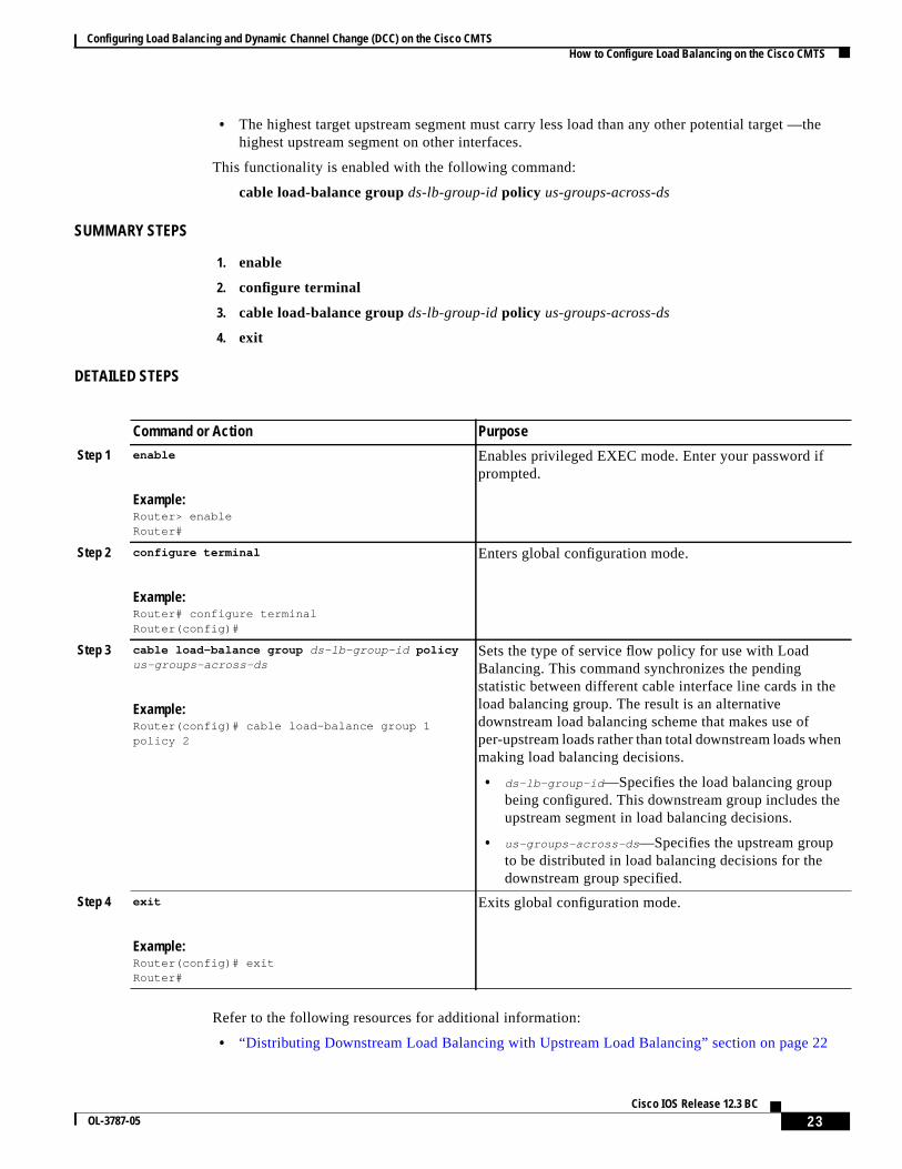
• The highest target upstream segment must carry less load than any other potential target —thehighest upstream segment on other interfaces.
This functionality is enabled with the following command:
In this example, a cable modem that comes online on the interface cable 5/0 Upstream 2 could potentiallycome online on the following interfaces:
• cable 3/0 upstream 2
• cable 4/0 upstream 2
• cable 6/0 upstream 2
• nowhere else, however
With downstream load balancing prior to Cisco IOS Release 12.3(17b)BC4, having 100 cable modemsper segment would be possible in an extreme case that distributes cable modems as follows:
The enhancement enables the following advantages and behaviors:
• This enhancement adds support for synchronizing thepending statistic between different cableinterface line cards and the network processing engine (NPE) so that a better decision can be madeabout where cable modems should be moved. This function can be used as a normal downstreamload balancing implementation, if desired.
• This enhancement adds theus-groups-across-dspolicy variable setting for configuring downstreamload balancing groups.
• This enhancement adds support for the output of theshow cable load-balance command.
For additional information, refer to the“Distributing Downstream Load Balancing with Upstream LoadBalancing” section on page 22.
Configuring Load Balancing and Dynamic Channel Change (DCC) on the Cisco CMTS Information on the Load Balancing on the Cisco CMTS Feature
13Cisco IOS Release 12.3 BC
OL-3787-05
Interaction with Spectrum Management
Cisco cable interface line cards support a number of features to maximize channel bandwidth and tominimize the impact of ingress noise on cable modem traffic. These features have the following impactsupon load-balancing operations:
• Frequency hopping—Frequency hopping does not affect the load balancing algorithm, because itdoes not change either the bandwidth of a channel nor the number of cable modems on an interface.
• Dynamic modulation changes—The dynamic modulation feature affects the load-balancingalgorithm because it typically switches an interface from a higher-bandwidth modulation profile toa lower-bandwidth modulation profile in response to noise conditions on the interface.
For example, if an upstream is configured for 16-QAM modulation, sufficient noise levels couldswitch the upstream to a QPSK modulation profile. Depending on the load-balancing configuration,this could then result in the movement of cable modems to other channels. Similarly, when the noiseconditions improve, and the modulation is returned to the original, higher-bandwidth profile, thecable modems could be moved again to rebalance the upstream channels.
• Channel width changes—The Cisco uBR-MC16S cable interface line card supports automaticchanges to the channel width in response to noise conditions. Because changing the channel widthaffects the throughput of a channel, this also affects the load-balancing algorithm.
For example, if noise makes the current channel width unusable, the Cisco uBR-MC16S cardreduces the channel width until it finds a usable channel width. Because this reduces the availablebandwidth on the channel, the load-balancing algorithm moves cable modems to rebalance theupstreams.
In addition, the Cisco uBR-MC16S card does not automatically restore the original channel widthwhen noise conditions improve. Instead, the card changes the channel width only when it performsa subsequent frequency hop, either in response to additional noise conditions or when an operatorperforms a manual frequency hop. When the hop occurs, the card then searches for the largestpossible channel width, and this could result in another movement of cable modems to rebalance thechannels.
BenefitsThe Load Balancing on the Cisco CMTS feature provides the following benefits to cable serviceproviders and their partners and customers:
• Provides a method that service providers can use for efficient bandwidth utilization, especially whenusing multiple upstream channels per fiber node.
• Allows service providers to expand their networks in an efficient manner, avoiding the cost of havingto install additional fiber optic equipment and further segmenting the physical plant.
• Load balancing on downstreams enables efficient bandwidth usage when using multiple downstreamchannels per fiber mode to enable Video over IP and other services that require high-bandwidthreal-time streams.
• Load balancing of upstreams and downstreams does not require any change to the provisioningservers or to any DOCSIS configuration files.
• Load balancing of upstreams and downstreams does not require any administrator or userintervention (such as manually resetting cable interfaces or manually rebooting cable modems).
• Load balancing can be used with the virtual interfaces feature on the Cisco uBR-MC5X20S/U/T/Hcable interface line cards to provide load balancing for configurable MAC domains.
Configuring Load Balancing and Dynamic Channel Change (DCC) on the Cisco CMTS How to Configure Load Balancing on the Cisco CMTS
14Cisco IOS Release 12.3 BC
OL-3787-05
• Allows service providers to equally balance their downstreams as cable modems register, so thatcable modems do not all attempt to register on the same downstream, resulting in many cablemodems failing to register and having to search for a new downstream.
• Cable modems can be moved among downstream and upstream channels without having to manuallychange any network parameters such as IP address.
• Allows service providers to stay ahead of customers’ bandwidth demands by dynamicallyresponding to current load-usage conditions.
• Allows service providers to optimize the load-balancing parameters for critical services, such asVoice over IP (VoIP).
How to Configure Load Balancing on the Cisco CMTSThe following sections describe how to create and configure load-balance groups, to enable loadbalancing on the Cisco CMTS. Each task is marked as required or optional, as appropriate.
• Creating a Load-Balance Group (required), page 14
• Configuring a Load-Balance Group (optional), page 15
• Assigning Interfaces to a Load-Balance Group (required), page 18
• Excluding Cable Modems from a Load-Balance Group (optional), page 21
Creating a Load-Balance Group (required)This section describes how to create a load-balance group. You must create at least one load-balancegroup before the Cisco CMTS will begin load balancing cable modems.
Configuring Load Balancing and Dynamic Channel Change (DCC) on the Cisco CMTS How to Configure Load Balancing on the Cisco CMTS
15Cisco IOS Release 12.3 BC
OL-3787-05
DETAILED STEPS
Command or Action Purpose
Step 1 enable
Example:Router> enableRouter#
Enables privileged EXEC mode. Enter your password ifprompted.
Step 2 configure terminal
Example:Router# configure terminalRouter(config)#
Enters global configuration mode.
Step 3 cable load-balance group n [ method modem |method service-flows | method utilization ]
Example:Router(config)# cable load-balance group 10method service-flows enforceRouter(config)# cable load-balance group 11method modemRouter(config)# cable load-balance group 12method utilization enforceRouter(config)#
Creates a load-balance group with the followingparameters:
• n = Number of the load-balance group. Valid range is 1to 80, with no default.
Note In later Cisco IOS Releases, such as release12.3(17a)BC, you can create a maximum of 80load-balance groups on each chassis. The olderlimitation was 20. However, in prior Cisco IOSreleases, you can reuse those load-balance groupson different sets of cable interfaces, as long as theyare in different domains. If downstream channelsare not included in a load-balance group, then eachdownstream channel can be considered a separatedomain.
• method modem= (Optional) Specifies that theload-balance group should use the number of activecable modems on an interface to determine the currentload (default).
• method service-flows= (Optional) Specifies that theload-balance group should use the number of activeservice flow IDs (SFIDs) on an interface to determinethe current load.
• method utilization = (Optional) Specifies that theload-balance group should use an interface’s currentpercentage of utilization to determine the current load.(To avoid unnecessary movement of cable modems, theutilization method does not perform load balancinguntil the amount of utilization on an interface is at25 percent or more.)
Step 4 exit
Example:Router(config)# exitRouter#
Exits global configuration mode.
Configuring Load Balancing and Dynamic Channel Change (DCC) on the Cisco CMTS How to Configure Load Balancing on the Cisco CMTS
16Cisco IOS Release 12.3 BC
OL-3787-05
Configuring a Load-Balance Group (optional)This section describes how to configure a load-balance group. All steps are optional, unless you want tochange the default load-balance configuration.
Enables privileged EXEC mode. Enter your password ifprompted.
Step 2 configure terminal
Example:Router# configure terminalRouter(config)#
Enters global configuration mode.
Step 3 cable load-balance group n [ interval seconds ]
Example:Router(config)# cable load-balance group 10interval 30Router(config)#
Modify how often the Cisco CMTS checks each interface todetermine the current load.
• n = Number of the load-balance group. Valid range is 1to 80, with no default.
Note In later Cisco IOS Releases, such as release12.3(17a)BC, you can create a maximum of 80load-balance groups on each chassis. The olderlimitation was 20. However, in prior Cisco IOSreleases, you can reuse those load-balance groupson different sets of cable interfaces, as long as theyare in different domains. If downstream channelsare not included in a load-balance group, then eachdownstream channel can be considered a separatedomain.
• seconds= Minimum time between when cable modemscan be moved to load balance the interfaces. One cablemodem at most is moved during each interval timeperiod. The valid range is 0 to 3600 seconds, with adefault value of 10 seconds.
Configuring Load Balancing and Dynamic Channel Change (DCC) on the Cisco CMTS How to Configure Load Balancing on the Cisco CMTS
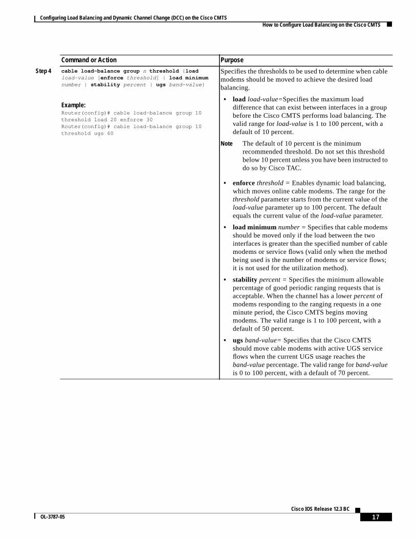
Example:Router(config)# cable load-balance group 10threshold load 20 enforce 30Router(config)# cable load-balance group 10threshold ugs 60
Specifies the thresholds to be used to determine when cablemodems should be moved to achieve the desired loadbalancing.
• load load-value=Specifies the maximum loaddifference that can exist between interfaces in a groupbefore the Cisco CMTS performs load balancing. Thevalid range forload-valueis 1 to 100 percent, with adefault of 10 percent.
Note The default of 10 percent is the minimumrecommended threshold. Do not set this thresholdbelow 10 percent unless you have been instructed todo so by Cisco TAC.
• enforce threshold =Enables dynamic load balancing,which moves online cable modems. The range for thethresholdparameter starts from the current value of theload-value parameter up to 100 percent. The defaultequals the current value of theload-value parameter.
• load minimum number =Specifies that cable modemsshould be moved only if the load between the twointerfaces is greater than the specified number of cablemodems or service flows (valid only when the methodbeing used is the number of modems or service flows;it is not used for the utilization method).
• stability percent =Specifies the minimum allowablepercentage of good periodic ranging requests that isacceptable. When the channel has a lowerpercentofmodems responding to the ranging requests in a oneminute period, the Cisco CMTS begins movingmodems. The valid range is 1 to 100 percent, with adefault of 50 percent.
• ugsband-value=Specifies that the Cisco CMTSshould move cable modems with active UGS serviceflows when the current UGS usage reaches theband-valuepercentage. The valid range forband-valueis 0 to 100 percent, with a default of 70 percent.
Command or Action Purpose
Configuring Load Balancing and Dynamic Channel Change (DCC) on the Cisco CMTS How to Configure Load Balancing on the Cisco CMTS
18Cisco IOS Release 12.3 BC
OL-3787-05
Note The load-balancing algorithms assume a relatively even distribution of usage among modems. In thesituation where one cable modem creates the bulk of the load on an interface, the load-balancingthresholds should be configured for a value above the load created by that single modem. You shouldcheck for this situation whenever the load-balancing algorithm is moving a large number of modemsfrom one interface to another.
Assigning Interfaces to a Load-Balance Group (required)This section describes how to assign cable interfaces (both downstreams and upstreams) to aload-balance group. A cable interface does not participate in load-balancing operations until it is amember of a load-balance group.
Restrictions
When assigning cable interfaces to load balance groups, be aware of the following restrictions:
• A downstream or upstream can belong to only one load-balance group.
• All downstreams and upstreams in a load-balance group must share physical connectivity to thesame group of cable modems. Downstreams can be in a separate load-balance group than upstreams,but all downstreams or all upstreams that have the same RF physical connectivity must be membersof the same load-balance group. You cannot distribute downstreams or upstreams that share physicalconnectivity across multiple load-balance groups.
Step 5 cable load-balance group n policy ugs
Example:Router(config)# cable load-balance group 10policy ugsRouter(config)#
Allows the Cisco CMTS to move cable modems that haveactive UGS service flows to enforce the load balancingpolicy.
• n = Number of the load-balance group. Valid range is 1to 80, with no default.
Note In later Cisco IOS Releases, such as release12.3(17a)BC, you can create a maximum of 80load-balance groups on each chassis. The olderlimitation was 20. However, in prior Cisco IOSreleases, you can reuse those load-balance groupson different sets of cable interfaces, as long as theyare in different domains. If downstream channelsare not included in a load-balance group, then eachdownstream channel can be considered a separatedomain.
Step 6 exit
Example:Router(config)# exitRouter#
Exits global configuration mode.
Command or Action Purpose
Configuring Load Balancing and Dynamic Channel Change (DCC) on the Cisco CMTS How to Configure Load Balancing on the Cisco CMTS
19Cisco IOS Release 12.3 BC
OL-3787-05
• All interfaces in a load-balance group use the same load-balancing parameters. By default, all cablemodems on those interfaces are included in load-balancing operations. However, you can excludeone or more particular cable modems from being moved in load-balancing operations (see the“Excluding Cable Modems from a Load-Balance Group (optional)” section on page 21).
SUMMARY STEPS
1. enable
2. configure terminal
3. interface cablex/y
4. cable load-balance groupn
5. cable downstream frequencyfreq-hz
6. cable upstreamuport load-balance groupn
7. exit
8. exit
DETAILED STEPS
Command or Action Purpose
Step 1 enable
Example:Router> enableRouter#
Enables privileged EXEC mode. Enter your password ifprompted.
Enters interface configuration mode for the specified cableinterface.
Step 4 cable load-balance group n
Example:Router(config-if)# cable load-balance group 10Router(config-if)#
Assigns the downstream interface to the specifiedload-balance group.
• n = Number of the load-balance group. Valid range is 1to 80, with no default.
Note In later Cisco IOS Releases, such as release12.3(17a)BC, you can create a maximum of 80load-balance groups on each chassis. The olderlimitation was 20. However, in prior Cisco IOSreleases, you can reuse those load-balance groupson different sets of cable interfaces, as long as theyare in different domains. If downstream channelsare not included in a load-balance group, then eachdownstream channel can be considered a separatedomain.
Configuring Load Balancing and Dynamic Channel Change (DCC) on the Cisco CMTS How to Configure Load Balancing on the Cisco CMTS
Specifies the known downstream center frequency to beused on this cable interface. This is an informational-onlyconfiguration on cable interfaces that use an externalupconverter, but it is still required for load balancing so thatthe Cisco CMTS knows what frequencies it should usewhen moving cable modems from one downstream toanother.
The freq-hzparameter specifies the frequency in Hz, with avalid range of 54,000,000 to 858,000,000. Depending onthe channel width, the range of center frequency that isacceptable to a CM is 91,000,000 to 857,000,000 Hz.
Step 6 cable upstream uport load-balance group n
Example:Router(config-if)# cable upstream 0load-balance group 10Router(config-if)#
Assigns an upstream port to the specified load-balancegroup.
• uport = Upstream port number. Valid range starts with0 and ends with a value that depends on the number ofupstream ports on the cable interface line card.
• n = Number of the load-balance group. Valid range is 1to 80, with no default.
Note In later Cisco IOS Releases, such as release12.3(17a)BC, you can create a maximum of 80load-balance groups on each chassis. The olderlimitation was 20. However, in prior Cisco IOSreleases, you can reuse those load-balance groupson different sets of cable interfaces, as long as theyare in different domains. If downstream channelsare not included in a load-balance group, then eachdownstream channel can be considered a separatedomain.
Note RepeatStep 3 throughStep 6 as needed for each downstream cable interface and its upstream ports thatshould belong to this group.
Step 7 exit
Example:Router(config-if)# exitRouter(config)#
Exits interface configuration mode.
Step 8 exit
Example:Router(config)# exitRouter#
Exits global configuration mode.
Command or Action Purpose
Configuring Load Balancing and Dynamic Channel Change (DCC) on the Cisco CMTS How to Configure Load Balancing on the Cisco CMTS
21Cisco IOS Release 12.3 BC
OL-3787-05
Excluding Cable Modems from a Load-Balance Group (optional)This section describes how to exclude a particular cable modem, or all cable modems from a particularvendor, from participating in static or dynamic load-balancing operations, and optionally marking themodems for passive load balancing. This task is optional, because, by default, cable modems on aninterface participate in whatever load-balancing operations have been configured.
Note This step might be required for some cable modems that are not DOCSIS-compliant. Such cable modemscan go offline for long periods of time when load balancing is attempted using DOCSIS MAC messages.If this is the case, use this command to exclude such cable modems from load-balancing operations untilthe modem can be upgraded to DOCSIS-compliant software.
Tip You must exclude cable modems that require specific upstream channels or downstream frequencies.Load balancing cannot be done when cable modems are assigned specific channels or frequencies intheir DOCSIS configuration files.
Enables privileged EXEC mode. Enter your password ifprompted.
Step 2 configure terminal
Example:Router# configure terminalRouter(config)#
Enters global configuration mode.
Configuring Load Balancing and Dynamic Channel Change (DCC) on the Cisco CMTS How to Configure Load Balancing on the Cisco CMTS
22Cisco IOS Release 12.3 BC
OL-3787-05
Distributing Downstream Load Balancing with Upstream Load BalancingCisco IOS Release 12.3(17b)BC4 enables the optional configuration of making downstream loadbalancing decisions as follows:
• The target downstream segment is in the same downstream load balancing group as the sourcedownstream segment.
• The upstream load balancing group can be set for the corresponding channel on which a cablemodem is balanced.
• The Cisco CMTS automatically locates the upstream segment for a load balancing group andprocesses the upstream group status on the source interface that has the lowest load.
• The target downstream segment must have an upstream channel set in the upstream load balancinggroup.
Specifies that one or more cable modems should beexcluded from load-balancing operations.
• mac-address— Hardware (MAC) address of anindividual cable modem to be excluded from loadbalancing. (You cannot specify a multicast MACaddress.)
• oui-value —Organization unique identifier (OUI) valuefor a vendor whose cable modems are to be excludedfrom load balancing. The OUI is composed of threehexadecimal bytes separated by colons or periods.
By default, the cable modems are excluded from dynamicand static load balancing, but they continue to participate inpassive load balancing. Use the following options toexclude the cable modems from others combinations of loadbalancing:
• enforce— (Optional) Excludes the cable modems fromdynamic load balancing, but they continue toparticipate in static load balancing.
• static — (Optional) Excludes the cable modems fromstatic load balancing, but they continue to participate inpassive load balancing and dynamic load balancing.
• strict — (Optional) Excludes the cable modems fromall forms of load balancing.
• static strict — (Optional) Excludes the cable modemfrom static and passive load balancing, but theycontinue to participate in dynamic load balancing.
Step 4 exit
Example:Router(config)# exitRouter#
Exits global configuration mode.
Command or Action Purpose
Configuring Load Balancing and Dynamic Channel Change (DCC) on the Cisco CMTS How to Configure Load Balancing on the Cisco CMTS
23Cisco IOS Release 12.3 BC
OL-3787-05
• The highest target upstream segment must carry less load than any other potential target —thehighest upstream segment on other interfaces.
This functionality is enabled with the following command:
Refer to the following resources for additional information:
• “Distributing Downstream Load Balancing with Upstream Load Balancing” section on page 22
Command or Action Purpose
Step 1 enable
Example:Router> enableRouter#
Enables privileged EXEC mode. Enter your password ifprompted.
Step 2 configure terminal
Example:Router# configure terminalRouter(config)#
Enters global configuration mode.
Step 3 cable load-balance group ds-lb-group-id policyus-groups-across-ds
Example:Router(config)# cable load-balance group 1policy 2
Sets the type of service flow policy for use with LoadBalancing. This command synchronizes the pendingstatistic between different cable interface line cards in theload balancing group. The result is an alternativedownstream load balancing scheme that makes use ofper-upstream loads rather than total downstream loads whenmaking load balancing decisions.
• ds-lb-group-id —Specifies the load balancing groupbeing configured. This downstream group includes theupstream segment in load balancing decisions.
• us-groups-across-ds —Specifies the upstream groupto be distributed in load balancing decisions for thedownstream group specified.
Step 4 exit
Example:Router(config)# exitRouter#
Exits global configuration mode.
Configuring Load Balancing and Dynamic Channel Change (DCC) on the Cisco CMTS How to Configure Load Balancing on the Cisco CMTS
Examples The following example illustrates this command and one supported implementation:
Router(config)# cable load-balance group 1 policy 2Router(config)#
In this example, a cable modem that comes online on the interface cable 5/0 Upstream 2 could potentiallycome online on the following interfaces:
• cable 3/0 upstream 2
• cable 4/0 upstream 2
• cable 6/0 upstream 2
• nowhere else, however
With downstream load balancing prior to Cisco IOS Release 12.3(17b)BC4, having 100 cable modemsper segment would be possible in an extreme case that distributes cable modems as follows:
Configuring Load Balancing and Dynamic Channel Change (DCC) on the Cisco CMTS How to Configure Load Balancing on the Cisco CMTS
25Cisco IOS Release 12.3 BC
OL-3787-05
Verifying Load Balancing Operations (optional)This section describes how to use thetest cable load-balanceandshow cable load-balancecommandsto verify the configuration and operation of the Load Balancing on the Cisco CMTS feature.
SUMMARY STEPS
1. enable
2. test cable load-balancemac-address [ucc | upstream] [count]
Tests the operation of the current load-balancing configuration bymoving a cable modem to a new upstream.
• mac-address= Hardware (MAC) address of the cable modemto be moved in the load-balancing test. (This cable modemmust be online.)
• ucc = (Optional) Moves the cable modem to a new upstreamchannel by sending an Upstream Channel Change (UCC)request message.
• upstream = (Optional) Moves the cable modem to a newupstream channel by forcing the cable modem offline, andthen instructing it to the new upstream channel when itreregisters.
• count= (Optional) Number of times to perform the test. Thevalid range is 1 to 80, with a default of 1.
Note In later Cisco IOS Releases, such as release 12.3(17a)BC,you can create a maximum of 80 load-balance groups oneach chassis. The older limitation was 20. However, inprior Cisco IOS releases, you can reuse thoseload-balance groups on different sets of cable interfaces,as long as they are in different domains. If downstreamchannels are not included in a load-balance group, theneach downstream channel can be considered a separatedomain.
Configuring Load Balancing and Dynamic Channel Change (DCC) on the Cisco CMTS How to Configure Load Balancing on the Cisco CMTS
26Cisco IOS Release 12.3 BC
OL-3787-05
Examples
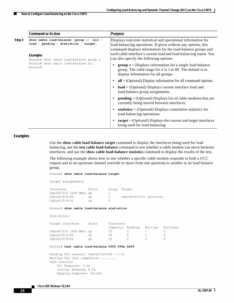
Use theshow cable load-balance target command to display the interfaces being used for loadbalancing, use thetest cable load-balancecommand to test whether a cable modem can move betweeninterfaces, and use theshow cable load-balance statistics command to display the results of the test.
The following example shows how to test whether a specific cable modem responds to both a UCCrequest and to an upstream channel override to move from one upstream to another in its load balancegroup.
Router# show cable load-balance target
Target assignments:
Interface State Group TargetCable5/0/0 (669 MHz) up 1Cable5/0/0/U0 up 1 Cable5/0/0/U1 [enforce]Cable5/0/0/U1 up 1
Router# show cable load-balance statistics
Statistics:
Target interface State Transfers Complete Pending Retries FailuresCable5/0/0 (669 MHz) up 15 0 1 0Cable5/0/0/U0 up 33 0 1 0Cable5/0/0/U1 up 22 0 2 0
Router# test cable load-balance 0000.394e.4e59
Sending UCC request: Cable5/0/0/U0 --> U1Waiting for test completion ........Test results: UCC Response: 0.0s Initial Ranging: 8.5s Ranging Complete: failed.
Step 3 show cable load-balance [ group n] [ all |load | pending | statistics | target ]
Example:Router# show cable load-balance group 1Router# show cable load-balance allRouter#
Displays real-time statistical and operational information forload-balancing operations. If given without any options, thiscommand displays information for the load-balance groups andeach cable interface’s current load and load-balancing status. Youcan also specify the following options:
• group n = Displays information for a single load-balancegroup. The valid range forn is 1 to 80. The default is todisplay information for all groups.
• all = (Optional) Display information for all command options.
• load = (Optional) Displays current interface load andload-balance group assignments.
• pending = (Optional) Displays list of cable modems that arecurrently being moved between interfaces.
• target = (Optional) Displays the current and target interfacesbeing used for load balancing.
Command or Action Purpose
Configuring Load Balancing and Dynamic Channel Change (DCC) on the Cisco CMTS How to Configure Load Balancing on the Cisco CMTS
27Cisco IOS Release 12.3 BC
OL-3787-05
Modem replied to DOCSIS ping.Test summary: UCC Response: success rate 100% min 0.0s max 0.0s avg 0.0s Initial Ranging: success rate 100% min 8.5s max 8.5s avg 8.5sTesting US Channel Override: Cable5/0/0/U1 --> U0Waiting for test completion ...........Test results: Initial Ranging: 8.5s Ranging Complete: failed. Modem replied to DOCSIS ping.Test summary: UCC Response: success rate 100% min 0.0s max 0.0s avg 0.0s Initial Ranging: success rate 100% min 8.5s max 8.5s avg 8.5s
Router# show cable load-balance statistics
Statistics:
Target interface State Transfers Complete Pending Retries FailuresCable5/0/0 (669 MHz) up 15 0 1 0Cable5/0/0/U0 up 34 0 1 0Cable5/0/0/U1 up 23 0 2 0
Router#
The following example shows how to test whether a specific modem responds to a UCC request to movefrom one upstream to another in its load balance group:
Router# show cable load-balance statistics
Statistics:
Target interface State Transfers Complete Pending Retries FailuresCable5/0/0 (669 MHz) up 15 0 1 0Cable5/0/0/U0 up 34 0 1 0Cable5/0/0/U1 up 23 0 2 0
Router# test cable load-balance 0007.0e01.4129 ucc 1
Sending UCC request: Cable5/0/0/U0 --> U1Waiting for test completion ........Test results: UCC Response: 0.0s Initial Ranging: 10.3s Ranging Complete: 11.2s Modem replied to DOCSIS ping.Test summary: UCC Response: success rate 100% min 0.0s max 0.0s avg 0.0s Initial Ranging: success rate 100% min 10.3s max 10.3s avg 10.3s Ranging Complete: success rate 100% min 11.2s max 11.2s avg 11.2s
Router# show cable load-balance statistics
Statistics:
Target interface State Transfers Complete Pending Retries FailuresCable5/0/0 (669 MHz) up 15 0 1 0Cable5/0/0/U0 up 35 0 1 0Cable5/0/0/U1 up 24 0 2 0
Router#
Configuring Load Balancing and Dynamic Channel Change (DCC) on the Cisco CMTS Configuration Examples for Load Balancing on the Cisco CMTS
28Cisco IOS Release 12.3 BC
OL-3787-05
Configuration Examples for Load Balancing on the Cisco CMTSThis section provides the following configuration examples:
• Load-Balance Group Example (Static Load Balancing), page 28
• Load-Balance Group Example (Passive Load Balancing), page 28
• Load-Balance Group Example (Dynamic Load Balancing), page 29
• Interface Configuration Example, page 29
• Sample Configuration for Upstreams and Downstreams, page 29
Load-Balance Group Example (Static Load Balancing)This sample configuration shows a number of load-balance groups being configured for staticload-balancing operations, with at least one example for each method of calculating the load on aninterface.
cable load-balance group 1 method modemcable load-balance group 2 modem service-flowscable load-balance group 3 modem utilizationcable load-balance group 3 threshold load 20cable load-balance group 3 interval 30cable load-balance group 5 method modemcable load-balance group 5 threshold load 20cable load-balance group 5 threshold ugs 60cable load-balance group 5 policy ugscable load-balance group 10 modem service-flowscable load-balance group 10 threshold load 10
Load-Balance Group Example (Passive Load Balancing)This sample configuration shows a number of load-balance groups being configured for staticload-balancing operations. Thecable load-balance excludecommand marks a number of cable modemsfor passive load balancing, while excluding them from static load-balancing operations.
cable load-balance group 1 method modemcable load-balance group 2 modem service-flowscable load-balance group 3 modem utilizationcable load-balance group 3 threshold load 20cable load-balance group 3 interval 30cable load-balance group 5 method modemcable load-balance group 5 threshold load 20cable load-balance group 5 threshold ugs 60cable load-balance group 5 policy ugscable load-balance group 10 modem service-flowscable load-balance group 10 threshold load 10!cable load-balance exclude oui 00.04.00cable load-balance exclude oui 00.03.00 staticcable load-balance exclude oui 0C.00.00cable load-balance exclude modem 0001.0203.0405 staticcable load-balance exclude modem 0C0B.0A09.0807
Configuring Load Balancing and Dynamic Channel Change (DCC) on the Cisco CMTS Configuration Examples for Load Balancing on the Cisco CMTS
29Cisco IOS Release 12.3 BC
OL-3787-05
Load-Balance Group Example (Dynamic Load Balancing)This sample configuration shows a number of load-balance groups being configured for dynamicload-balancing operations.
cable load-balance group 1 method modemcable load-balance group 1 threshold load 20 enforce 20cable load-balance group 2 modem service-flowscable load-balance group 2 threshold load 10 enforce 10cable load-balance group 3 modem utilizationcable load-balance group 3 threshold load 20 enforce 40cable load-balance group 3 interval 30cable load-balance group 5 method modemcable load-balance group 5 threshold load 20 enforce 25cable load-balance group 5 threshold ugs 60cable load-balance group 5 policy ugscable load-balance group 10 modem service-flowscable load-balance group 10 threshold load 10 enforce 10
Interface Configuration ExampleThis sample configuration for a cable interface shows a downstream and its four upstreams beingassigned to the same load-balance group:
interface Cable3/0 ip address 10.10.71.1 255.255.255.0 ip helper-address 10.10.71.1 cable downstream annex B cable downstream modulation 64qam cable downstream interleave-depth 32 cable downstream channel-id 0 cable upstream 0 frequency 8000000 cable upstream 0 channel-width 200000 cable upstream 0 minislot-size 64 cable upstream 0 load-balance group 1 no cable upstream 0 shutdown cable upstream 1 frequency 30000000 cable upstream 1 power-level 0 cable upstream 1 channel-width 3200000 cable upstream 1 load-balance group 1 no cable upstream 1 shutdown cable upstream 2 frequency 22000000 cable upstream 2 power-level 0 cable upstream 2 load-balance group 1 no cable upstream 2 shutdown cable upstream 3 frequency 15008000 cable upstream 3 power-level 0 cable upstream 3 load-balance group 1 no cable upstream 3 shutdown cable load-balance group 1
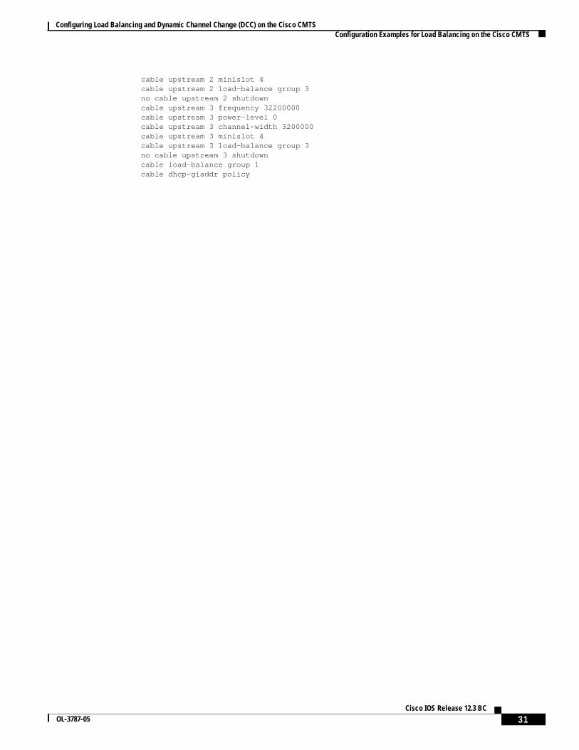
Sample Configuration for Upstreams and DownstreamsThe following example shows the configuration necessary to create the load-balance groups that areshown inFigure 1 on page 10, with load-balance group 1 being used for the two downstreams,load-balance group 2 being used for six upstreams, and load-balance group 3 being used for theremaining two upstreams.
Configuring Load Balancing and Dynamic Channel Change (DCC) on the Cisco CMTS Configuration Examples for Load Balancing on the Cisco CMTS
30Cisco IOS Release 12.3 BC
OL-3787-05
! Load-balance group for the two downstreamscable load-balance group 1 threshold load 10 enforce 20! Load-balance group for the first six upstreamscable load-balance group 2 threshold load 10 enforce 20! Load-balance group for the last two upstreamscable load-balance group 3 threshold load 10 enforce 20!interface Cable5/0 ip address 11.1.0.1 255.255.0.0 secondary ip address 1.2.3.1 255.255.255.0 cable bundle 1 master cable downstream annex B cable downstream modulation 64qam cable downstream interleave-depth 32 cable downstream frequency 453000000 cable downstream channel-id 1 cable upstream 0 frequency 15000000 cable upstream 0 power-level 0 cable upstream 0 channel-width 3200000 cable upstream 0 minislot 4 cable upstream 0 load-balance group 2 no cable upstream 0 shutdown cable upstream 1 frequency 18200000 cable upstream 1 power-level 0 cable upstream 1 channel-width 3200000 cable upstream 1 minislot 4 cable upstream 1 load-balance group 2 no cable upstream 1 shutdown cable upstream 2 frequency 21400000 cable upstream 2 power-level 0 cable upstream 2 channel-width 3200000 cable upstream 2 minislot 4 cable upstream 2 load-balance group 2 no cable upstream 2 shutdown cable upstream 3 frequency 24600000 cable upstream 3 power-level 0 cable upstream 3 channel-width 3200000 cable upstream 3 minislot 4 cable upstream 3 load-balance group 2 no cable upstream 3 shutdown cable load-balance group 1 cable dhcp-giaddr policyinterface Cable5/1 cable bundle 1 cable downstream annex B cable downstream modulation 64qam cable downstream interleave-depth 32 cable downstream frequency 459000000 cable downstream channel-id 2 cable upstream 0 frequency 29000000 cable upstream 0 power-level 0 cable upstream 0 channel-width 3200000 cable upstream 0 minislot 4 cable upstream 0 load-balance group 2 no cable upstream 0 shutdown cable upstream 1 frequency 32200000 cable upstream 1 power-level 0 cable upstream 1 channel-width 3200000 cable upstream 1 minislot 4 cable upstream 1 load-balance group 2 no cable upstream 1 shutdown cable upstream 2 frequency 29000000 cable upstream 2 power-level 0 cable upstream 2 channel-width 3200000
Configuring Load Balancing and Dynamic Channel Change (DCC) on the Cisco CMTS Configuration Examples for Load Balancing on the Cisco CMTS
31Cisco IOS Release 12.3 BC
OL-3787-05
cable upstream 2 minislot 4 cable upstream 2 load-balance group 3 no cable upstream 2 shutdown cable upstream 3 frequency 32200000 cable upstream 3 power-level 0 cable upstream 3 channel-width 3200000 cable upstream 3 minislot 4 cable upstream 3 load-balance group 3 no cable upstream 3 shutdown cable load-balance group 1 cable dhcp-giaddr policy
Configuring Load Balancing and Dynamic Channel Change (DCC) on the Cisco CMTS How to Configure Dynamic Channel Change for Load Balancing
32Cisco IOS Release 12.3 BC
OL-3787-05
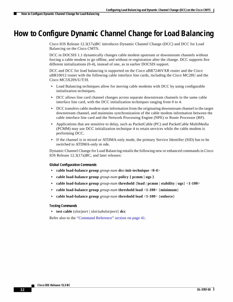
How to Configure Dynamic Channel Change for Load BalancingCisco IOS Release 12.3(17a)BC introduces Dynamic Channel Change (DCC) and DCC for LoadBalancing on the Cisco CMTS.
DCC in DOCSIS 1.1 dynamically changes cable modem upstream or downstream channels withoutforcing a cable modem to go offline, and without re-registration after the change. DCC supports fivedifferent initializations (0-4), instead of one, as in earlier DOCSIS support.
DCC and DCC for load balancing is supported on the Cisco uBR7246VXR router and the CiscouBR10012 router with the following cable interface line cards, including the Cisco MC28U and theCisco MC5X20S/U/T/H.
• Load Balancing techniques allow for moving cable modems with DCC by using configurableinitialization techniques.
• DCC allows line card channel changes across separate downstream channels in the same cableinterface line card, with the DCC initialization techniques ranging from 0 to 4.
• DCC transfers cable modem state information from the originating downstream channel to the targetdownstream channel, and maintains synchronization of the cable modem information between thecable interface line card and the Network Processing Engine (NPE) or Route Processor (RP).
• Applications that are sensitive to delay, such as PacketCable (PC) and PacketCable MultiMedia(PCMM) may use DCC initialization technique 4 to retain services while the cable modem isperforming DCC.
• If the channel is in mixed or ATDMA-only mode, the primary Service Identifier (SID) has to beswitched to ATDMA-only m ode.
Dynamic Channel Change for Load Balancing entails the following new or enhanced commands in CiscoIOS Release 12.3(17a)BC, and later releases:
Refer also to the“Command Reference” section on page 41.
Configuring Load Balancing and Dynamic Channel Change (DCC) on the Cisco CMTS How to Configure Dynamic Channel Change for Load Balancing
33Cisco IOS Release 12.3 BC
OL-3787-05
Configuring DCC for Load Balancing on the Cisco CMTSTo configure the DCC feature for load balancing, use the following steps in global configuration mode.Values indicated are sample values that may differ from your own.
SUMMARY STEPS
1. enable
2. configure terminal
3. cable load-balance groupgroup-numdcc-init-technique number
Step 3 cable load-balance group group-numdcc-init-technique number
Example:Router(config)# cable load-balance group 1dcc-init-technique 0
Sets the DCC initialization technique for the specified loadbalancing group. The initialization technique number can rangefrom 0-4.
• Initialization technique 0—reinitializes the MAC address.The cable modem needs to go offline and reregister itself onthe new channel.
• Initialization technique 1—broadcasts the initial ranging.The cable modem is kept online and re-registration isavoided, but this technique requires completion of initialranging.
• Initialization technique 2—performs periodic ranging. Thecable modem is kept online and allowed to start on the newchannel with periodic ranging.
• Initialization technique 3—performs initial ranging orperiodic ranging. This technique enables the cable modem tochoose a ranging method between initial ranging and periodicranging.
• Initialization technique 4—uses the new channel directly.The cable modem may start to send data immediately on thenew channel without any initial ranging or periodic ranging.
Configuring Load Balancing and Dynamic Channel Change (DCC) on the Cisco CMTS How to Configure Dynamic Channel Change for Load Balancing
34Cisco IOS Release 12.3 BC
OL-3787-05
Testing Dynamic Channel Change for Load BalancingTo test and verify DCC for load balancing, use the following two commands:
• test cable dcc
• show controllers cable
These commands, and usage guidelines, are described in the“Command Reference” section on page 41.
Example:Router(config)# cable load-balance group 1policy pcmmRouter(config)# cable load-balance group 1policy ugs
Enables load balancing of cable modems with either PacketCableMultiMedia (PCMM) service flows, Unsolicited Grant Service(UGS) service flows, or both PCMM and UGS service flows.Applies these setting to the specified load balancing group.
• pcmm—Enables balancing of cable modems with activePCMM service flows.
• ugs—Enables balancing of cable modems with active UGSservice flows.
Example:Router(config)# cable load-balance group 1threshold load 75 enforce
Sets the enforce threshold for the specified load balancing group.
• <1-100>—Threshold value in percentage
• enforce—Keyword enables the enforce threshold, specifiedin a percentage.
Step 8 end
Example:Router(config)# endRouter#
Returns to Privileged EXEC mode.
Command or Action Purpose
Configuring Load Balancing and Dynamic Channel Change (DCC) on the Cisco CMTS Configuration Examples of Dynamic Channel Change (DCC) for Load Balancing
35Cisco IOS Release 12.3 BC
OL-3787-05
Configuration Examples of Dynamic Channel Change (DCC) forLoad Balancing
The following example of the running configuration illustrates DCC for load balancing implementedwith the commands above. Refer also to the additionalshow run example further below.
Modem Group Source interface Target interface Retries
The following example of the running configuration illustrates the DCC for load balancing implementedwith the commands above.
Router# show runBuilding configuration...
Current configuration : 11889 bytes!version 12.3no service padservice timestamps debug datetime msecservice timestamps log datetime msecno service password-encryption!hostname Router!boot-start-markerboot-end-marker!enable secret 5 $1$tEvV$8xICVVbFm10hx0hAB7DO90enable password lab!no cable qos permission createno cable qos permission updatecable qos permission modemscable load-balance group 1 threshold load 75 enforcecable load-balance group 1 threshold stability 75cable load-balance group 1 policy ugscable load-balance group 1 threshold ugs 75
Configuring Load Balancing and Dynamic Channel Change (DCC) on the Cisco CMTS Configuration Examples of Dynamic Channel Change (DCC) for Load Balancing
36Cisco IOS Release 12.3 BC
OL-3787-05
cable load-balance group 1 policy pcmmcable load-balance group 1 threshold pcmm 75no aaa new-modelip subnet-zero!!ip cefno ip domain lookup!!interface GigabitEthernet0/1 ip address 10.14.1.130 255.255.0.0 duplex auto speed auto media-type rj45 no negotiation auto!interface GigabitEthernet0/2
The following example of theshow cable load allcommand illustrates the DCC for load balancingimplemented with the commands above.
Modem Group Source interface Target interface Retries
The following example illustrates a DCC load balancing group with the default DCC initializationtechnique. The first command configures load balancing group 1:
Router# cable load-balance group 1 threshold load 10 enforce
This configuration create a dynamic load balancing group with the following default settings:
cable load-balance group 1 method modemcable load-balance group 1 threshold load 10 enforcecable load-balance group 1 interval 10cable load-balance group 1 dcc-init-technique 0
Configuring Load Balancing and Dynamic Channel Change (DCC) on the Cisco CMTS System Error Messages for Load Balancing
37Cisco IOS Release 12.3 BC
OL-3787-05
The following example changes this DCC load balancing configuration immediately above toinitialization technique 4:
Router# cable load-balance group 1 dcc-init-technique 4
Note By default, UGS and PCMM policies are not turned on, so that cable modems with active voice call orPCMM calls do participate in load balancing.
System Error Messages for Load BalancingCisco IOS Release 12.2(15)BC1 adds the following system error messages to support the LoadBalancing on the Cisco CMTS feature.
%UBR7100-4-LB_MODEM_FAILED%UBR7200-4-LB_MODEM_FAILED%UBR10000-4-LB_MODEM_FAILED: Failed to move modem [enet] from [chars] to [chars].
Explanation The CMTS was trying to load-balance the two indicated interfaces, but was unable tomove the specified cable modem from its current interface to the new interface after five attempts.
Recommended Action Verify that both interfaces are connected and passing traffic. Also look for anypossible RF noise problems. Check thecable load-balance groupconfiguration to ensure that thetwo downstreams or upstreams are combined in the same node and share the same physicalconnectivity (which is required when interfaces are part the same load-balance group).
Explanation The CMTS load-balancing subsystem disabled the indicated cable interface, because itcould not move cable modems either to it or from it.
Recommended Action Verify that the interface is connected and passing traffic. Also look for anypossible RF noise problems. Check thecable load-balance groupconfiguration to ensure that theinterface’s load-balance group contains only those interfaces that are combined in the same nodeand share the same physical connectivity (which is required when interfaces are part the sameload-balance group).
Configuring Load Balancing and Dynamic Channel Change (DCC) on the Cisco CMTS Additional References
38Cisco IOS Release 12.3 BC
OL-3787-05
Additional ReferencesFor additional information related to Load Balancing on the Cisco CMTS, refer to the followingreferences:
Configuring Load Balancing and Dynamic Channel Change (DCC) on the Cisco CMTS Additional References
39Cisco IOS Release 12.3 BC
OL-3787-05
The following MIB information is updated in Cisco IOS Release 12.3(17a)BC in support of DCC forload balancing:
docsQosDCCReqs OBJECT-TYPE
SYNTAX Counter32
MAX-ACCESS read-only
STATUS current
DESCRIPTION "The number of Dynamic Channel Change Request messages traversing an interface.This count is nonzero only on downstream direction rows."
::= { docsQosDynamicServiceStatsEntry 16 }
docsQosDCCRsps OBJECT-TYPE
SYNTAX Counter32
MAX-ACCESS read-only
STATUS current
DESCRIPTION "The number of Dynamic Channel Change Response messages traversing an interface.This count is nonzero only on upstream direction rows."
::= { docsQosDynamicServiceStatsEntry 17 }
docsQosDCCAcks OBJECT-TYPE
SYNTAX Counter32
MAX-ACCESS read-only
STATUS current
DESCRIPTION "The number of Dynamic Channel Change Acknowledgement messages traversing aninterface. This count is nonzero only on downstream direction rows."
::= { docsQosDynamicServiceStatsEntry 18 }
docsQosDCCs OBJECT-TYPE
SYNTAX Counter32
MAX-ACCESS read-only
STATUS current
DESCRIPTION "The number of successful Dynamic Channel Change transactions. This count isnonzero only on downstream direction rows."
::= { docsQosDynamicServiceStatsEntry 19 }
docsQosDCCFails OBJECT-TYPE
SYNTAX Counter32
MAX-ACCESS read-only
STATUS current
DESCRIPTION "The number of failed Dynamic Channel Change transactions. This count is nonzeroonly on downstream direction rows."
::= { docsQosDynamicServiceStatsEntry 20 }
Configuring Load Balancing and Dynamic Channel Change (DCC) on the Cisco CMTS Additional References
40Cisco IOS Release 12.3 BC
OL-3787-05
RFCs
Technical Assistance
RFCs1
1. Not all supported RFCs are listed.
Title
RFC 1163 A Border Gateway Protocol
RFC 1164 Application of the Border Gateway Protocol in the Internet
RFC 1483 Multiprotocol Encapsulation over ATM Adaptation Layer 5
RFC 2233 DOCSIS OSSI Objects Support
RFC 2283 Multiprotocol Extensions for BGP-4
RFC 2665 DOCSIS Ethernet MIB Objects Support
RFC 2669 Cable Device MIB
Description Link
Technical Assistance Center (TAC) home page,containing 30,000 pages of searchable technicalcontent, including links to products, technologies,solutions, technical tips, and tools. RegisteredCisco.com users can log in from this page to accesseven more content.
Configuring Load Balancing and Dynamic Channel Change (DCC) on the Cisco CMTS Command Reference
41Cisco IOS Release 12.3 BC
OL-3787-05
Command ReferenceThe following commands are needed to enable and configure the Load Balancing feature for the CiscoCMTS. This section includes commands for Dynamic Channel Change (DCC) for Load Balancing.Otherwise, refer to theCisco Broadband Cable Command Reference Guideon Cisco.com and toprocedures in this document for complete information.
Dynamic Channel Change Commands for Load Balancing
Dynamic Channel Change for Load Balancing entails the following new or enhanced commands in CiscoIOS Release 12.3(17a)BC, and later releases. This section describes commands supporting DCC forLoad Balancing. Also refer to theCisco Broadband Cable Command Reference Guideon Cisco.com andto procedures in this document for additional command information.
Configuring Load Balancing and Dynamic Channel Change (DCC) on the Cisco CMTS cable load-balance group
42Cisco IOS Release 12.3 BC
OL-3787-05
cable load-balance groupTo set multiple parameters for Load Balancing with Dynamic Channel Change (DCC), use the followingcommand in global configuration mode. To remove this c onfiguration, use theno form of this command.
Command Default Load balancing is not configured by default on the Cisco CMTS.
Command Modes Global configuration mode.
Command History
Examples The following example illustrates configuration of the initialization techniques specified for DCC:
Router(config)# cable load-balance group 1 dcc-init-technique 4
For further examples of this command, and related keywords, refer to related commands, and refer alsoto the“Configuring DCC for Load Balancing on the Cisco CMTS” section on page 33.
Usage Guidelines This command is subject to the restrictions and prerequisites described inConfiguring Load Balancingand Dynamic Channel Change (DCC) on the Cisco CMTS.
12.3(17a)BC This command was introduced on the Cisco uBR10012 router and the CiscouBR7246VXR router, with supporting broadband processing engines(BPEs) or cable interface line cards on the respective routers.
Command Description
cable load-balance groupdcc-init-technique
Sets the initialization technique for Dynamic Channel Change(DCC) for Load Balancing.
cable load-balance group policy Sets the type of service flow for use with Load Balancing andDCC, whether PacketCable MultiMedia (PCMM) orUnsolicited Grant Service (UGS).
cable load-balance group threshold Sets the threshold levels for corresponding service flow typesfor the specified Load Balancing group, supporting DynamicChannel Change (DCC)
show controllers cable Displays statistics for Dynamic Channel Change (DCC) forload balancing.
test cable dcc Performs testing functions for Load Balancing with DCC
Configuring Load Balancing and Dynamic Channel Change (DCC) on the Cisco CMTS cable load-balance group dcc-init-technique
44Cisco IOS Release 12.3 BC
OL-3787-05
cable load-balance group dcc-init-techniqueTo set the initialization technique for Dynamic Channel Change (DCC), use the following command inglobal configuration mode. To remove this c onfiguration, use the no form of this command.
Command Default By default, DCC uses the 0 initialization technique, unless otherwise specified.
Command Modes Global configuration mode.
Command History
Examples The following example illustrates configuration of the initialization techniques specified for DCC:
Router(config)# cable load-balance group 1 dcc-init-technique 4
Usage Guidelines This command is subject to the restrictions and prerequisites described inConfiguring Load Balancingand Dynamic Channel Change (DCC) on the Cisco CMTS.
DCC for Load Balancing supports the following types of initialization techniques:
• Initialization technique 0—reinitializes the MAC address. The cable modem needs to go offline andreregister on the new channel.
• Initialization technique 1—broadcasts the initial ranging. The cable modems are kept online andre-registration is avoided, but this technique requires completion of initial ranging.
• Initialization technique 2—performs periodic ranging. The cable modems are kept online andallowed to start on the new channel with periodic ranging.
• Initialization technique 3—performs initial ranging or periodic ranging. This technique enables thecable modem to choose a ranging method between initial ranging and periodic ranging.
• Initialization technique 4—uses the new channel directly. The cable modem may start to send dataimmediately on the new channel without any initial ranging or periodic ranging.
12.3(17a)BC This command was introduced on the Cisco uBR10012 router and the CiscouBR7246VXR router, with supporting broadband processing engines(BPEs) or cable interface line cards on the respective routers.
cable load-balance group Sets multiple parameters for Load Balancing with DCC.
cable load-balance group policy Sets the type of service flow for use with Load Balancing andDCC, whether PacketCable MultiMedia (PCMM) orUnsolicited Grant Service (UGS).
cable load-balance group threshold Sets the threshold levels for corresponding service flow typesfor the specified Load Balancing group, supporting DynamicChannel Change (DCC)
show controllers cable Displays statistics for Dynamic Channel Change (DCC) forload balancing.
test cable dcc Performs testing functions for Load Balancing with DCC
Configuring Load Balancing and Dynamic Channel Change (DCC) on the Cisco CMTS cable load-balance group policy
46Cisco IOS Release 12.3 BC
OL-3787-05
cable load-balance group policyTo set the type of service flow for use with Load Balancing and Dynamic Channel Change (DCC), usethe following command in global configuration mode. This command supports PacketCable MultiMedia(PCMM) or Unosolicited Grant Service (UGS) to the specified Load Balancing group.
In the case of PCMM, this command enables cable modems with active PCMM flows to participate inload balancing after a certain threshold is reached.
Note Defining the UGS policy in load balancing is required, in additional to UGS that is used for PCMM calls.
To remove this configuration, use theno form of this command.
no cable load-balance groupgroup-num policy { pcmm | ugs}
Syntax Description
Command Default By default, cable modems with active PCMM are not load balanced.
By default, cable modems with active UGS flows are not load balanced.
Command Modes Global configuration mode.
Command History
Examples The following examples illustrate configuration commands for PacketCable MultiMedia (PCMM) andUnsolicited Grant Service (UGS) for DCC:
Router(config)# cable load-balance group 1 policy pcmmRouter(config)# cable load-balance group 1 policy ugs
Usage Guidelines This command is subject to the restrictions and prerequisites described inConfiguring Load Balancingand Dynamic Channel Change (DCC) on the Cisco CMTS.
group-num Specifies the load balancing group number being configured.
pcmm Enables balancing of modems with active PCMM service flows.
ugs Enables balancing of modems with active UGS service flows.
Release Modification
12.3(17a)BC This command was introduced on the Cisco uBR10012 router and the CiscouBR7246VXR router, with supporting broadband processing engines(BPEs) or cable interface line cards on the respective routers.
cable load-balance group Sets multiple parameters for Load Balancing with DCC.
cable load-balance groupdcc-init-technique
Sets the initialization technique for Dynamic Channel Change(DCC) for Load Balancing.
cable load-balance group threshold Sets the threshold levels for corresponding service flow typesfor the specified Load Balancing group, supporting DynamicChannel Change (DCC)
show controllers cable Displays statistics for Dynamic Channel Change (DCC) forload balancing.
test cable dcc Performs testing functions for Load Balancing with DCC
Configuring Load Balancing and Dynamic Channel Change (DCC) on the Cisco CMTS cable load-balance group threshold
48Cisco IOS Release 12.3 BC
OL-3787-05
cable load-balance group thresholdTo set the threshold levels and corresponding service flow types for the specified Load Balancing group,supporting Dynamic Channel Change (DCC) on the Cisco router, use the following command in globalconfiguration mode. To remove threshold settings, use theno form of this command.
Command Default Load balancing is not configured by default on the Cisco CMTS.
Command Modes Global configuration mode.
Command History
Examples The following command specifies the reserved bandwidth threshold. Above this level, cable modemswith active PCMM service flows participate in load balancing, and the default threshold is 70%. Notethat if UGS is used for PCMM, the UGS threshold needs to be crossed as well. The default UGSthreshold is 70%)
Router(config)# cable load-balance group 4 threshold pcmm <pcmm-value>
load Interface load threshold settings
pcmm PCMM service flow threshold
stability Threshold for stability detection
ugs UGS service flow threshold
1-100 Interface utilization threshold in percentage of interface capacity.
load Interface load threshold settings
1-100 Threshold value in percentage
minimum Set minimum number of modems/flows difference before loadbalancingstarts
enforce Enters the enforce threshold
Release Modification
12.3(17a)BC This command was introduced on the Cisco uBR10012 router and the CiscouBR7246VXR router, with supporting broadband processing engines(BPEs) or cable interface line cards on the respective routers.
Configuring Load Balancing and Dynamic Channel Change (DCC) on the Cisco CMTS cable load-balance group threshold
49Cisco IOS Release 12.3 BC
OL-3787-05
Usage Guidelines In Cisco IOS releases prior to Cisco IOS Release 12.3(17a)BC, the load balancing default setting isUGS. This is not the case with Cisco IOS Release 12.3(17a)BC. In this latter release, and subsequentreleases, configuration is required if the cable modems with active UGS flows are desired to participatein load balancing.
This command is subject to the restrictions and prerequisites described inConfiguring Load Balancingand Dynamic Channel Change (DCC) on the Cisco CMTS.
Related Commands
Also refer to the following document on Cisco.com:
cable load-balance group Sets multiple parameters for Load Balancing with DCC.
cable load-balance groupdcc-init-technique
Sets the initialization technique for Dynamic Channel Change(DCC) for Load Balancing.
cable load-balance group policy Sets the type of service flow for use with Load Balancing andDCC, whether PacketCable MultiMedia (PCMM) orUnsolicited Grant Service (UGS).
show controllers cable Displays statistics for Dynamic Channel Change (DCC) forload balancing.
test cable dcc Performs testing functions for Load Balancing with DCC
Configuring Load Balancing and Dynamic Channel Change (DCC) on the Cisco CMTS show controllers cable
50Cisco IOS Release 12.3 BC
OL-3787-05
show controllers cableTo display statistics for Dynamic Channel Change (DCC) for load balancing, use theshow controllerscable command in privileged EXEC mode.
show controllers cable{ slot/port | slot/subslot/port} upstream | i DCC
show controllers cable{ slot/port | slot/subslot/port} downstream | i DCC
Syntax Description
Command Default Test functions are disabled by default.
Command Modes Privileged EXEC mode.
Command History
Examples The following commands and fields illustrate theshow controllers command used with DCC:
Router# show controllers cx/y upstream | i DCCDCC: 0 REQs n2 RSPs 0 ACKsRouter# show controllers cx/y downstream| i DCCDCC: n1 REQs 0 RSPs n3 ACKsn4 Successful DCCs n5 DCC FailuresDCC end of transaction counts:DCC unknown cause(e1) offline(e2) if down(e3) no cm(e4)DCC no resource(e5) no retries(e6) reject(e7) unknown state (e8)DCC rebuild err (e9) T15 timeout(e10) reinit MAC (e11) dcc succeeds(e12)
The fields in this example are as follows:
• n1—The number of DCC REQ messages traversing an interface, nonzero on downstream.
• n2—The number of DCC RSP messages traversing an interface, nonzero on upstream.
• n3—The number of DCC ACK messages traversing an interface, nonzero on downstream.
• n4—The number of successful DCC transactions, nonzero on downstream direction.
• n5—The number of failed DCC transactions, nonzero only on downstream direction
The above counters are DOCSIS specific DCC counters, which can also be collected via SNMP MIB.
slot/port Identifies a cable interface on the Cisco uBR10012 router. The following arevalid values:
• slot = 3 to 6
• port = 0 or 1, depending on the cable interface
slot/subslot/port Identifies a cable interface on the Cisco uBR10012 router. The following are thevalid values:
• slot = 5 to 8
• subslot = 0 or 1
• port = 0 to 4, depending on the cable interface
Release Modification
12.3(17a)BC This command was enhanced on the Cisco uBR10012 router and the CiscouBR7246VXR router, to display DCC information.
Configuring Load Balancing and Dynamic Channel Change (DCC) on the Cisco CMTS show controllers cable
51Cisco IOS Release 12.3 BC
OL-3787-05
The following summary illustrates classified DCC transaction end counts originated from the interfacewith the aboveshow controllerscommand example.
• e1—The number of DCC transactions ended with unknown causes.
• e2—The number of DCC transactions ended due to modem’s going offline.
• e3—The number of DCC transactions ended due to interface down.
• e4—The number of DCC transactions ended due to nonexistent cm.
• e5—The number of DCC transactions ended due to insufficient resource on target.
• e6—The number of DCC transactions ended due to exhausted DCC-REQ retries.
• e7—The number of DCC transactions ended due to rejected DCC-REQ.
• e8—The number of DCC transactions ended due to unknown DCC state.
• e9—The number of DCC transactions ended due to failure to assign cm on the target.
• e10—The number of DCC transactions ended due to T15 time out.
• e11—The number of DCC transactions ended due to CM MAC reinitialization.
• e12—The number of DCC transactions ended successfully.
The following example shows information when moving a cable modem to a different upstream channelusing DCC initialization technique 1. This example moves the cable modem 0012.17ea.f563 frominterface c7/1/0 upstream 1 to interface c7/1/1 upstream 0 using DCC initialization technique 1:
Router# show cable modemMAC Address IP Address I/F MAC Prim RxPwr Timing Num BPI State Sid (dB) Offset CPE Enb State Sid (dB) Offset CPE Enb0012.17ea.f563 12.0.0.2 C7/1/0/U1 online 4 0.00 2449 0 N
Router# test cable dcc 0012.17ea.f563 c7/1/1 0 1Router# show cable modemMAC Address IP Address I/F MAC Prim RxPwr Timing Num BPI State Sid (dB) Offset CPE Enb0012.17ea.f563 12.0.0.2 C7/1/1/U0 online 3 0.00 2451 0 N
Below are further verification examples of DCC for load balancing, using theshow controllerscommand. In the following example, one DCC-RSP (depart) message is received on the source upstream.
DCC end of transaction counts: DCC unknown cause(0) offline(0) if down(0) no cm(0) DCC no resource(0) no retries(0) reject(0) unknown state (0) DCC rebuild err (0) T15 timeout(0) reinit MAC (0) dcc succeeds(1)(1 DCC transaction originated ended successfully)Router# show controllers c7/1/1 downstream | i DCC DCC: 0 REQs 0 RSPs 1 ACKs 0 Successful DCCs 0 DCC Failures(1 DCC-ACK message transmitted on the target downstream)
Configuring Load Balancing and Dynamic Channel Change (DCC) on the Cisco CMTS show controllers cable
52Cisco IOS Release 12.3 BC
OL-3787-05
Usage Guidelines This command is subject to the restrictions and prerequisites described inConfiguring Load Balancingand Dynamic Channel Change (DCC) on the Cisco CMTS.
Related Commands Command Description
test cable dcc Performs testing functions for Load Balancing with DCC
Configuring Load Balancing and Dynamic Channel Change (DCC) on the Cisco CMTS test cable dcc
53Cisco IOS Release 12.3 BC
OL-3787-05
test cable dccTo test Dynamic Channel Change for Load Balancing on the Cisco CMTS, use the following commandin global configuration mode.
test cable dcc [<mac-addr>|<ip-addr> | <cable-if-src> <sid>] <cable-if-target> <uschan>{ ranging-tech}
Syntax Description
Command Default Test functions are disabled by default.
Command Modes Global configuration mode.
Command History
Examples The following examples illustrate DCC verification, using thetest cable dcc command.
The following example moves a target cable modem, specified by MAC address, IP address or theprimary sid value on the source interface to a target downstream with the specified frequency using DCCintialization technique 0:
Router# test cable dcc [< mac-addr >|< ip-addr >|< cable-if-src ><sid >] frequency < freq-value >Frequency-value: <55000000-858000000> New Downstream Frequency in HZ.
The following example moves a target cable modem, specified by MAC address, IP address or theprimary sid value on the source interface to a upstream channel on a target downstream with theDCC-REQ TLV given in the specified HEX data.
The following example moves all cable modems on a source interface to a target downstream with thespecified frequency using DCC intialization technique 0.
Router# test cable dcc < cable-if-src > frequency < frequency-value >Frequency-value: <55000000-858000000> New Downstream Frequency in HZ.
mac-addr The MAC address of the cable modem to be moved for DCC test.
ip-addr The IP address of the cable modem to be moved for DCC test.
cable-if-src The name of the source downstream interface for the DCC transaction.
Sid Primary Service ID (sid) value.
cable-if-target The name of the target downstream interface for the DCC transaction.
uschan The upstream channel ID of the target upstream for the DCC transaction.
ranging-tech The initialization technique to be used for the DCC transaction, 0 is thedefault if not specified. Valid range is 0-4.
Release Modification
12.3(17a)BC This command was introduced on the Cisco uBR10012 router and the CiscouBR7246VXR router, with supporting broadband processing engines(BPEs) or cable interface line cards on the respective routers.
Configuring Load Balancing and Dynamic Channel Change (DCC) on the Cisco CMTS test cable dcc
54Cisco IOS Release 12.3 BC
OL-3787-05
Usage Guidelines This command is subject to the restrictions and prerequisites described inConfiguring Load Balancingand Dynamic Channel Change (DCC) on the Cisco CMTS.
Related Commands
Also refer to the following document on Cisco.com:
cable load-balance group Sets multiple parameters for Load Balancing with DCC.
cable load-balance groupdcc-init-technique
Sets the initialization technique for Dynamic Channel Change(DCC) for Load Balancing.
cable load-balance group policy Sets the type of service flow for use with Load Balancing andDCC, whether PacketCable MultiMedia (PCMM) orUnsolicited Grant Service (UGS).
cable load-balance group threshold Sets the threshold levels for corresponding service flow typesfor the specified Load Balancing group, supporting DynamicChannel Change (DCC)
show controllers cable Displays statistics for Dynamic Channel Change (DCC) forload balancing.
Configuring Load Balancing and Dynamic Channel Change (DCC) on the Cisco CMTS Glossary
55Cisco IOS Release 12.3 BC
OL-3787-05
GlossaryThis section describes terms and acronyms that are used in this manual and not otherwise defined. Seethe Internetworking Terms and Acronyms for terms not included in this glossary.
active service flow—An admitted service flow that is available for packet transmissions between the cablemodem and the CMTS in either the upstream or the downstream direction.
admitted service flow—A provisioned or dynamically signaled service flow that is authorized, and forwhich resources have been reserved, but that is not active.
amplifier —Used on coaxial segments of a CATV plant to restore signal levels lost due to attenuation throughdistance.
availability —The long term ratio of the actual radio frequency (RF) channel operation time to the scheduledRF channel operation time (expressed as a percentage) based on a bit error rate (BER) assumption.
ATM —Asynchronous Transfer Mode.
bandwidth allocation map—The MAC management message that the CMTS uses to allocatetransmission opportunities to cable modems.
branch line—A coaxial cable that runs from a trunk line to a subscriber drop point. A branch line is alsoknown as a feeder cable.
cable interface line card—The modem front-end card of the cable router headend device, plugged intothe midplane. Each cable line card provides a number of radio frequency (RF) channels as externalinterfaces.
cable modem (CM)—A modulator/demodulator at subscriber locations that is used in conveying datacommunications on a cable television system.
cable modem termination system (CMTS)—A device that provides complementary functionality tocable modems to enable connectivity to a wide area network (WAN).
cable access router—A modular chassis-based router that is optimized for the data over CATV HFCapplication.
CATV —Refers to any cable-based system of television services (either coaxial or fiber cable).
CLI —command-line interface.
codec—coder-decoder. A device that typically uses pulse code modulation to transform analog signals intoa digital bit stream and digital signals back into analog.
CPE—customer premises equipment. One or more PCs located at the customer site.
distribution hub —A smaller or remote headend distribution point for a CATV system. Video signals arereceived here from another site (headend) and are redistributed. Sometimes a small number of locallyoriginated signals are added. These signals might be city of information channels, HFC cable modem signals,and so on.
DOCSIS—Data-over-Cable Service Interface Specifications. Defines technical specifications for equipmentat both subscriber locations and cable operators' headends. Adoption of DOCSIS can accelerate deploymentof data-over-cable services and ensure interoperability of equipment throughout system operators'infrastructures.
downstream—A set of frequencies used to send data from a headend to a subscriber.
drop—A subscriber access point; the actual coaxial connection in a subscriber’s home.
Configuring Load Balancing and Dynamic Channel Change (DCC) on the Cisco CMTS Glossary
56Cisco IOS Release 12.3 BC
OL-3787-05
dynamic load balancing—A form of traffic-based load balancing in which cable modems are balancedamong upstreams and downstreams after they come online, while they are passing traffic. Dynamic loadbalancing must be enabled by using theenforce option of thecable load-balance group thresholdcommand.
fiber node (node)—An optical node (located in the outside plant distribution system) that terminates thefiber-based downstream signal as an electrical signal onto a coaxial RF cable. Each fiber node is defined tosupport a designated service area, defined either by the number of homes or by total amplifier cascade (thetotal number of active amplifiers in the longest line from the node to the end of the line).
headend—The endpoint of a broadcast network and central distribution point for a CATV system. Allstations transmit toward the headend; the headend then transmits toward the destination stations. Videosignals are received from a satellite (either colocated or remote), and the frequency is converted to theappropriate channels where it is combined with locally originated signals and is rebroadcast onto the HFCplant. For a CATV data system, the headend is the typical place to link between the HFC system and anyexternal data networks.
HFC—hybrid fiber-coaxial. Older CATV systems were provisioned using only coaxial cable. Modernsystems use fiber transport from the headend to an optical node located in the neighborhood to reduce systemnoise. Coaxial runs from the node to the subscriber. The fiber plant is generally a star configuration with alloptical node fibers terminating at a headend. The coaxial part of the system is generally a trunk and branchconfiguration.
MAC —media access control. Typically refers to the lower of the two sublayers of the data link layer that isdefined by the IEEE. The MAC sublayer handles access to shared physical transmission media. In DOCSISnetworks, MAC also refers to the management messages that are sent between the CMTS and CM to maintainconnectivity over the cable network.
optical node—A device used to convert broadband RF to and from a fiber-optic signal. An optical node isusually located in the outside field.
passive load balancing—Load balancing that is done at the time a cable modem registers by ignoringa cable modem’s ranging request (RNG-REQ) message until it uses the correct target channels. Passiveload balancing is not performed for cable modems unless you exclude those modems from using staticload balancing with thecable load-balance exclude command.
provisioning—The programming of allocatable resources, such as operating parameters, upstream anddownstream frequencies, slot assignments, and logical identifiers, in headend and subscriber modems.
ranging—The adjustment of the subscriber modem upstream timing offset to ensure that an upstream packetinserted into a TDMA slot aligns correctly with the headend modem upstream frame.
registration—The process of a subscriber modem signing on to the cable network by identifying itself to theheadend.
SAID—See security association identifier.
security association identifier—A Baseline Privacy security identifier between a CMTS and a cablemodem.
service flow—A MAC-layer transport service that provides unidirectional transport of packets from theupper service layer entity to the RF device.
service identifier (SID)—A service flow identifier (14 bits) assigned by the CMTS to an active or admittedupstream service flow.
SFID—service flow identifier.
SGCP—Simple Gateway Control Protocol. Controls Voice-over-IP (VoIP) gateways by an external callcontrol element (called a call agent).
SID— See service identifier.
Configuring Load Balancing and Dynamic Channel Change (DCC) on the Cisco CMTS Glossary
57Cisco IOS Release 12.3 BC
OL-3787-05
SNMP—Simple Network Management Protocol.
static load balancing—Load balancing that is done at the time a cable modem registers by specifyingthe proper target channel in the Downstream Frequency Override or an Upstream Channel ID Overridefield in the ranging response (RNG-RSP) message that the CMTS sends to the cable modem. Static loadbalancing is done by default for cable modems in a load-balance group, unless you exclude thosemodems from static load balancing using thecable load-balance exclude command.
status request—The periodic querying of subscriber cable modems by the headend for alarm and servicerequests.
tap—A passive device that divides a signal between the trunk or feeder lines and splits the signal into portsfor subscriber drop access.
TDM —time-division multiplexing. A technique in which information from multiple channels can beallocated bandwidth on a single wire, based on preassigned time slots. Bandwidth is allocated to each channelregardless of whether the station has data to transmit.
TDMA —time-division multiple access.
trunk line —A CATV backbone coaxial cable. This cable runs from an optical node through a specificneighborhood or service area.
UBR—universal broadband router. Refers to the family line of DOCSIS Cisco CMTS routers.
UGS—unsolicited grant service, which is an Upstream Flow Scheduling Service Type that providesconstant bit rate (CBR) traffic onto service flows. UGS service flows support applications that requirereal-time traffic, such as Voice over IP and Video-on-Demand (VoD).
upstream—The set of frequencies used to send data from a subscriber to the headend.
VoIP—Voice over IP. The ability to carry normal telephone-style voice over an IP-based Internet withPOTS-like functionality, reliability, and voice quality. VoIP is a blanket term that generally refers to theCisco standards-based (for example, H.323 or SGCP) approach to IP voice traffic.
CCVP, the Cisco Logo, and the Cisco Square Bridge logo are trademarks of Cisco Systems, Inc.; Changing the Way We Work, Live, Play, and Learn is a service mark of Cisco Systems, Inc.; and Access Registrar, Aironet, BPX, Catalyst, CCDA, CCDP, CCIE, CCIP, CCNA, CCNP, CCSP, Cisco, the Cisco Certified Internetwork Expert logo, Cisco IOS, Cisco Press, Cisco Systems, Cisco Systems Capital, the Cisco Systems logo, Cisco Unity,Enterprise/Solver, EtherChannel, EtherFast, EtherSwitch, Fast Step, Follow Me Browsing, FormShare, GigaDrive, GigaStack, HomeLink, Internet Quotient, IOS, IP/TV, iQ Expertise, the iQ logo, iQ Net Readiness Scorecard, iQuick Study, LightStream, Linksys, MeetingPlace, MGX, Networking Academy, Network Registrar, Packet, PIX, ProConnect, RateMUX, ScriptShare, SlideCast, SMARTnet, StackWise, The Fastest Way to Increase Your Internet Quotient, and TransPath are registered trademarks of Cisco Systems, Inc. and/or its affiliates in the United States and certain other countries.
All other trademarks mentioned in this document or Website are the property of their respective owners. The use of the word partner does not imply a
Configuring Load Balancing and Dynamic Channel Change (DCC) on the Cisco CMTS Glossary