Hardware and Software Versions......................................................................................................2Network Diagram.....................................................................................................................................2Configurations.........................................................................................................................................3
show Commands....................................................................................................................................12Sampleshow Output..............................................................................................................................12Related Information...............................................................................................................................14
Cisco − Configuring MPLS Basic Traffic Engineering Using OSPF
Hardware and Software VersionsNetwork DiagramConfigurations
Quick Configuration GuideConfiguration Filesshow CommandsSample show OutputRelated Information
Introduction
This sample configuration shows how to implement traffic engineering (TE) on top of an existingMultiprotocol Label Switching (MPLS) network using Frame Relay and Open Shortest Path First (OSPF).Our example implements two dynamic tunnels (automatically set up by the ingress Label Switch Routers[LSR]) and two tunnels that use explicit paths.
TE is a generic name corresponding to the use of different technologies to optimize the utilization of a givenbackbone capacity and topology.
MPLS TE provides a way to integrate TE capabilities (such as those used on Layer 2 protocols like ATM)into Layer 3 protocols (IP). MPLS TE uses an extension to existing protocols (IntermediateSystem−to−Intermediate System (IS−IS), Resource Reservation Protocol (RSVP), OSPF) to calculate andestablish unidirectional tunnels that are set according to the network constraint. Traffic flows are mapped onthe different tunnels depending on their destination.
Functional Components
Component Description
IP tunnel interfaces Layer 2: an MPLS tunnel interface is the head of a LabelSwitched Path (LSP). It is configured with a set of resourcerequirements, such as bandwidth and priority. Layer 3: the LSPtunnel interface is the head−end of a unidirectional virtual linkto the tunnel destination.
RSVP with TE extension RSVP is used to establish and maintain LSP tunnels based onthe calculated path using PATH and RSVP Reservation(RESV) messages. The RSVP protocol specification has beenextended so that the RESV messages also distribute labelinformation.
Link−State Interior Gateway Protocol(IGP) [IS−IS or OSPF with TE
Used to flood topology and resource information from the linkmanagement module. IS−IS uses new Type−Length−Values
Cisco − Configuring MPLS Basic Traffic Engineering Using OSPF
MPLS TE path calculation module Operates at the LSP head only and determines a path usinginformation from the link−state database.
MPLS TE link management module At each LSP hop, this module performs link call admission onthe RSVP signaling messages, and bookkeeping of topologyand resource information to be flooded by OSPF or IS−IS.
Label switching forwarding Basic MPLS forwarding mechanism based on labels.
Hardware and Software Versions
This configuration was developed and tested using the software and hardware versions below.
Cisco IOS® Software Releases 12.0(11)S and 12.1(3a)T
Cisco 3600 routers•
•
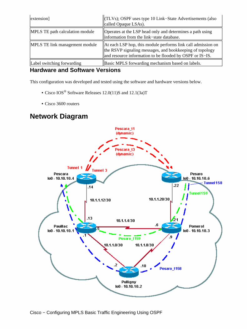
Network Diagram
Cisco − Configuring MPLS Basic Traffic Engineering Using OSPF
Configurations
Quick Configuration Guide
The following steps can be used to perform a quick configuration. For more detailed information, see MPLSTraffic Engineering and Enhancements.
Set up your network with the usual configuration. (In this case, we used Frame Relay.)
Note: It is mandatory to set up a loopback interface with an IP mask of 32 bits. This address will beused for the setup of the MPLS network and TE by the routing protocol. This loopback address mustbe reachable via the global routing table.
1.
Set up a routing protocol for the MPLS network. It must be a link−state protocol (IS−IS or OSPF). Inthe routing protocol configuration mode, enter the following commands:
mpls traffic−eng area X mpls traffic−eng router−id LoopbackN (must have a 255.255.255.255 mask)
♦
2.
Enable MPLS TE. Enter ip cef (or ip cef distributed if available in order to enhance performance) inthe general configuration mode. Enable MPLS (tag−switching ip) on each concerned interface. Entermpls traffic−engineering tunnel to enable MPLS TE.
3.
Enable RSVP by entering ip rsvp bandwidth XXX on each concerned interface.4.
Set up tunnels to be used for TE. There are many options that can be configured for MPLS TETunnel, but the tunnel mode mpls traffic−eng command is mandatory. The tunnel mpls traffic−engautoroute announce command announces the presence of the tunnel by the routing protocol.
5.
Note: Don't forget to use ip unnumbered loopbackN for the IP address of the tunnel interfaces.
This sample configuration shows two dynamic tunnels (Pescara_t1 and Pescara_t3) with different bandwidth(and priorities) going from the Pescara router to the Pesaro router, and two tunnels (Pesaro_t158 andPesaro_t159) using an explicit path going from Pesaro to Pescara.
Configuration Files
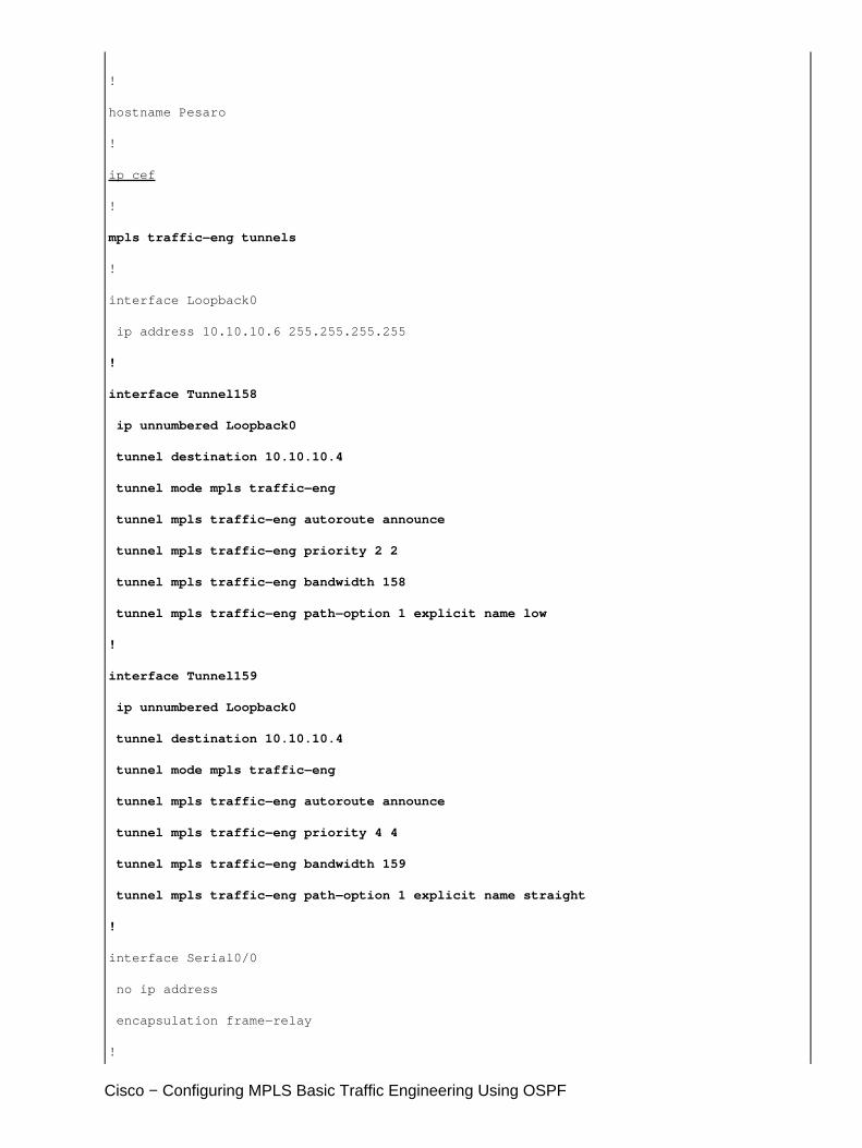
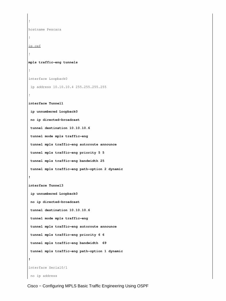
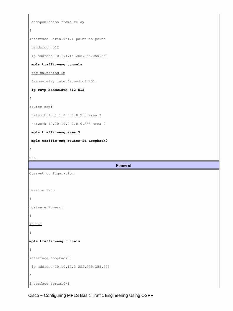
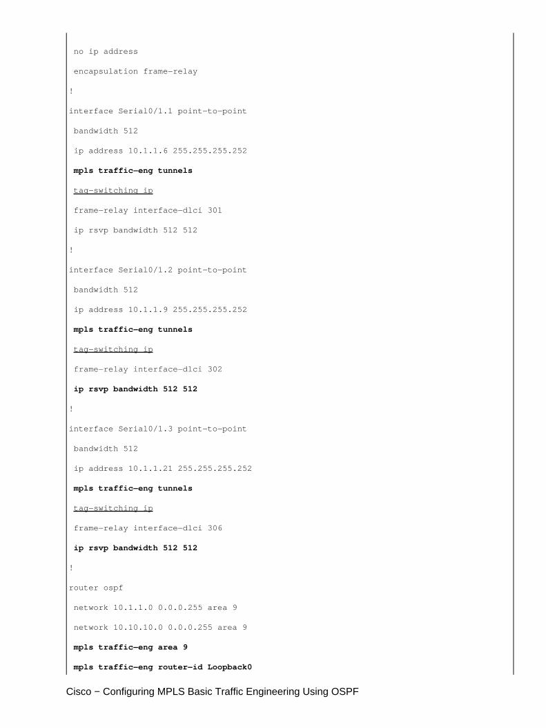
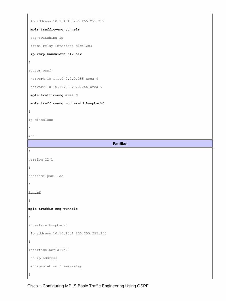
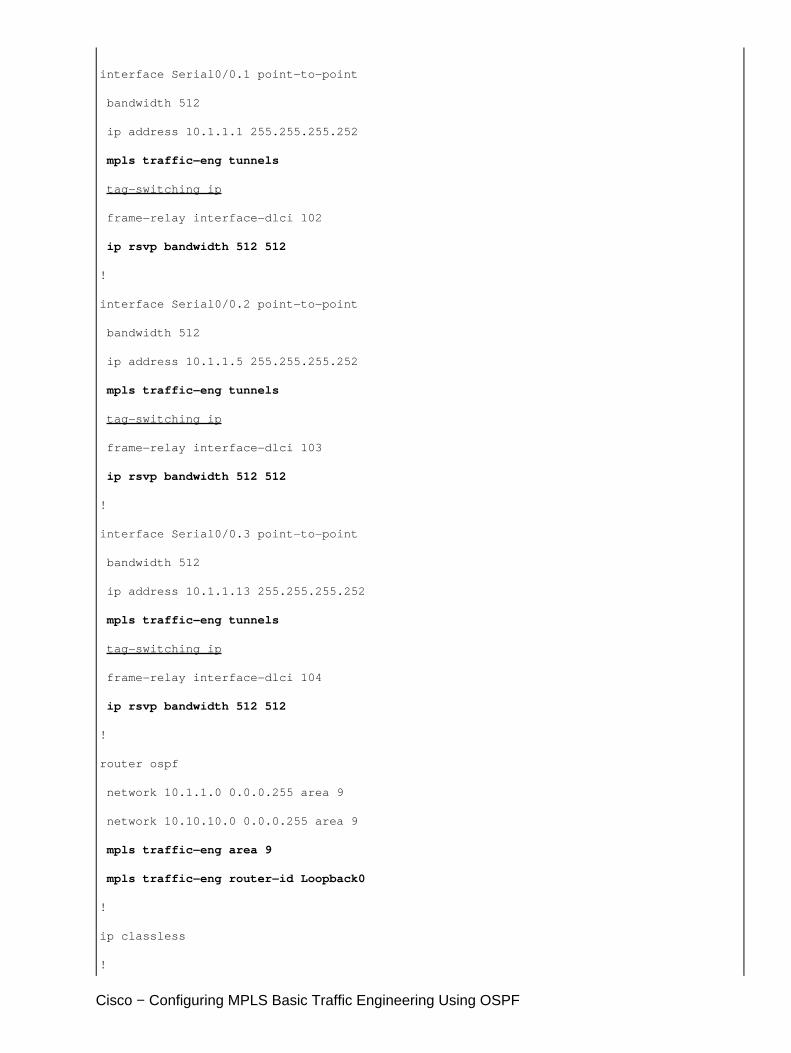
Only the relevant parts of the configuration files are included. Commands used to enable MPLS areunderlined; commands specific to TE (including RSVP) are in bold.
Pesaro
Current configuration:
!
version 12.1
Cisco − Configuring MPLS Basic Traffic Engineering Using OSPF
!
hostname Pesaro
!
ip cef
!
mpls traffic−eng tunnels
!
interface Loopback0
ip address 10.10.10.6 255.255.255.255
!
interface Tunnel158
ip unnumbered Loopback0
tunnel destination 10.10.10.4
tunnel mode mpls traffic−eng
tunnel mpls traffic−eng autoroute announce
tunnel mpls traffic−eng priority 2 2
tunnel mpls traffic−eng bandwidth 158
tunnel mpls traffic−eng path−option 1 explicit name low
!
interface Tunnel159
ip unnumbered Loopback0
tunnel destination 10.10.10.4
tunnel mode mpls traffic−eng
tunnel mpls traffic−eng autoroute announce
tunnel mpls traffic−eng priority 4 4
tunnel mpls traffic−eng bandwidth 159
tunnel mpls traffic−eng path−option 1 explicit name straight
!
interface Serial0/0
no ip address
encapsulation frame−relay
!
Cisco − Configuring MPLS Basic Traffic Engineering Using OSPF
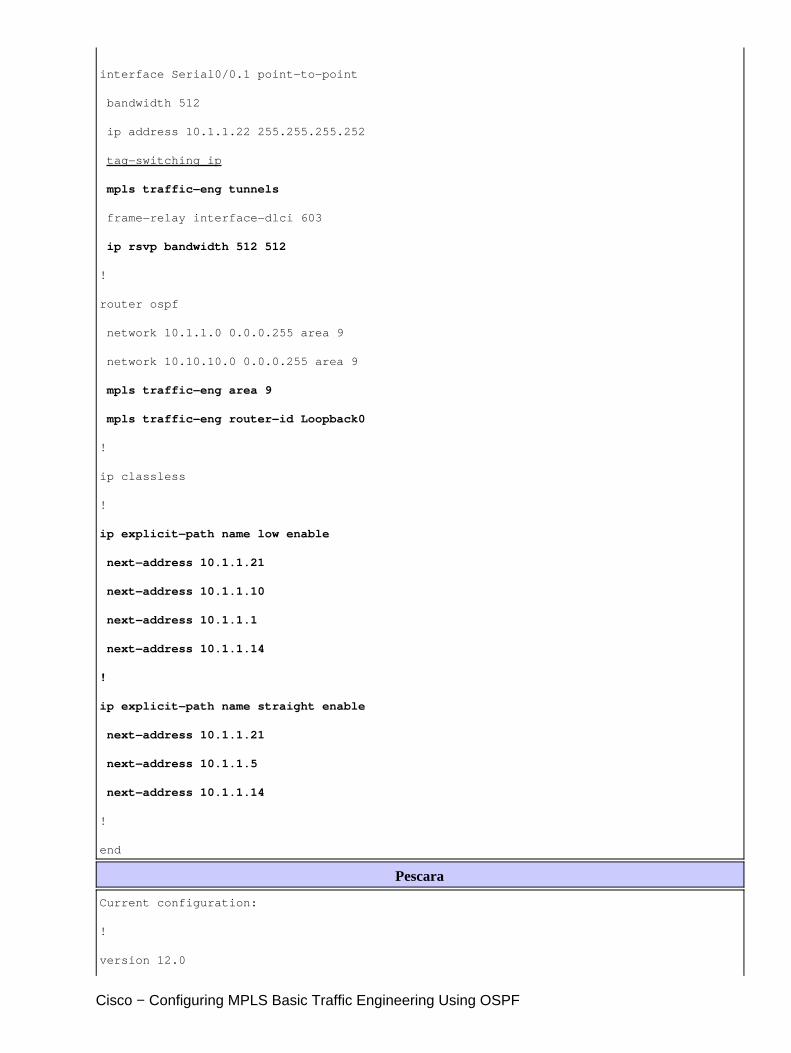
interface Serial0/0.1 point−to−point
bandwidth 512
ip address 10.1.1.22 255.255.255.252
tag−switching ip
mpls traffic−eng tunnels
frame−relay interface−dlci 603
ip rsvp bandwidth 512 512
!
router ospf
network 10.1.1.0 0.0.0.255 area 9
network 10.10.10.0 0.0.0.255 area 9
mpls traffic−eng area 9
mpls traffic−eng router−id Loopback0
!
ip classless
!
ip explicit−path name low enable
next−address 10.1.1.21
next−address 10.1.1.10
next−address 10.1.1.1
next−address 10.1.1.14
!
ip explicit−path name straight enable
next−address 10.1.1.21
next−address 10.1.1.5
next−address 10.1.1.14
!
end
Pescara
Current configuration:
!
version 12.0
Cisco − Configuring MPLS Basic Traffic Engineering Using OSPF
!
hostname Pescara
!
ip cef
!
mpls traffic−eng tunnels
!
interface Loopback0
ip address 10.10.10.4 255.255.255.255
!
interface Tunnel1
ip unnumbered Loopback0
no ip directed−broadcast
tunnel destination 10.10.10.6
tunnel mode mpls traffic−eng
tunnel mpls traffic−eng autoroute announce
tunnel mpls traffic−eng priority 5 5
tunnel mpls traffic−eng bandwidth 25
tunnel mpls traffic−eng path−option 2 dynamic
!
interface Tunnel3
ip unnumbered Loopback0
no ip directed−broadcast
tunnel destination 10.10.10.6
tunnel mode mpls traffic−eng
tunnel mpls traffic−eng autoroute announce
tunnel mpls traffic−eng priority 6 6
tunnel mpls traffic−eng bandwidth 69
tunnel mpls traffic−eng path−option 1 dynamic
!
interface Serial0/1
no ip address
Cisco − Configuring MPLS Basic Traffic Engineering Using OSPF
encapsulation frame−relay
!
interface Serial0/1.1 point−to−point
bandwidth 512
ip address 10.1.1.14 255.255.255.252
mpls traffic−eng tunnels
tag−switching ip
frame−relay interface−dlci 401
ip rsvp bandwidth 512 512
!
router ospf
network 10.1.1.0 0.0.0.255 area 9
network 10.10.10.0 0.0.0.255 area 9
mpls traffic−eng area 9
mpls traffic−eng router−id Loopback0
!
end
Pomerol
Current configuration:
version 12.0
!
hostname Pomerol
!
ip cef
!
mpls traffic−eng tunnels
!
interface Loopback0
ip address 10.10.10.3 255.255.255.255
!
interface Serial0/1
Cisco − Configuring MPLS Basic Traffic Engineering Using OSPF
no ip address
encapsulation frame−relay
!
interface Serial0/1.1 point−to−point
bandwidth 512
ip address 10.1.1.6 255.255.255.252
mpls traffic−eng tunnels
tag−switching ip
frame−relay interface−dlci 301
ip rsvp bandwidth 512 512
!
interface Serial0/1.2 point−to−point
bandwidth 512
ip address 10.1.1.9 255.255.255.252
mpls traffic−eng tunnels
tag−switching ip
frame−relay interface−dlci 302
ip rsvp bandwidth 512 512
!
interface Serial0/1.3 point−to−point
bandwidth 512
ip address 10.1.1.21 255.255.255.252
mpls traffic−eng tunnels
tag−switching ip
frame−relay interface−dlci 306
ip rsvp bandwidth 512 512
!
router ospf
network 10.1.1.0 0.0.0.255 area 9
network 10.10.10.0 0.0.0.255 area 9
mpls traffic−eng area 9
mpls traffic−eng router−id Loopback0
Cisco − Configuring MPLS Basic Traffic Engineering Using OSPF
!
ip classless
!
end
Pulligny
Current configuration:
!
version 12.1
!
hostname Pulligny
!
ip cef
!
mpls traffic−eng tunnels
!
interface Loopback0
ip address 10.10.10.2 255.255.255.255
!
interface Serial0/1
no ip address
encapsulation frame−relay
!
interface Serial0/1.1 point−to−point
bandwidth 512
ip address 10.1.1.2 255.255.255.252
mpls traffic−eng tunnels
tag−switching ip
frame−relay interface−dlci 201
ip rsvp bandwidth 512 512
!
interface Serial0/1.2 point−to−point
bandwidth 512
Cisco − Configuring MPLS Basic Traffic Engineering Using OSPF
ip address 10.1.1.10 255.255.255.252
mpls traffic−eng tunnels
tag−switching ip
frame−relay interface−dlci 203
ip rsvp bandwidth 512 512
!
router ospf
network 10.1.1.0 0.0.0.255 area 9
network 10.10.10.0 0.0.0.255 area 9
mpls traffic−eng area 9
mpls traffic−eng router−id Loopback0
!
ip classless
!
end
Pauillac
!
version 12.1
!
hostname pauillac
!
ip cef
!
mpls traffic−eng tunnels
!
interface Loopback0
ip address 10.10.10.1 255.255.255.255
!
interface Serial0/0
no ip address
encapsulation frame−relay
!
Cisco − Configuring MPLS Basic Traffic Engineering Using OSPF
interface Serial0/0.1 point−to−point
bandwidth 512
ip address 10.1.1.1 255.255.255.252
mpls traffic−eng tunnels
tag−switching ip
frame−relay interface−dlci 102
ip rsvp bandwidth 512 512
!
interface Serial0/0.2 point−to−point
bandwidth 512
ip address 10.1.1.5 255.255.255.252
mpls traffic−eng tunnels
tag−switching ip
frame−relay interface−dlci 103
ip rsvp bandwidth 512 512
!
interface Serial0/0.3 point−to−point
bandwidth 512
ip address 10.1.1.13 255.255.255.252
mpls traffic−eng tunnels
tag−switching ip
frame−relay interface−dlci 104
ip rsvp bandwidth 512 512
!
router ospf
network 10.1.1.0 0.0.0.255 area 9
network 10.10.10.0 0.0.0.255 area 9
mpls traffic−eng area 9
mpls traffic−eng router−id Loopback0
!
ip classless
!
Cisco − Configuring MPLS Basic Traffic Engineering Using OSPF
end
show Commands
General show commands are illustrated on the sample configuration for MPLS TE with IS−IS.
The following commands are specific to MPLS TE with OSPF and are illustrated below:
show ip ospf mpls traffic−eng link•
show ip ospf database opaque−area•
Sample show Output
You can use the show ip ospf mpls traffic−eng link command to see what will be advertised by OSPF at agiven router. The RSVP characteristics are shown in blue below, indicating the reservable bandwidth that isbeing advertised and used. You can see the bandwidth used by Pescara_t1 (at Priority 5) and Pescara_t3 (atPriority 6).
Pesaro# show ip ospf mpls traffic−eng link
OSPF Router with ID (10.10.10.61) (Process ID 9)
Area 9 has 1 MPLS TE links. Area instance is 3.
Links in hash bucket 48. Link is associated with fragment 0. Link instance is 3 Link connected to Point−to−Point network Link ID : 10.10.10.3 Pomerol Interface Address : 10.1.1.22 Neighbor Address : 10.1.1.21 Admin Metric : 195
Maximum bandwidth : 64000 Maximum reservable bandwidth : 64000 Number of Priority : 8 Priority 0 : 64000 Priority 1 : 64000 Priority 2 : 64000 Priority 3 : 64000 Priority 4 : 64000 Priority 5 : 32000 Priority 6 : 24000 Priority 7 : 24000 Affinity Bit : 0x0
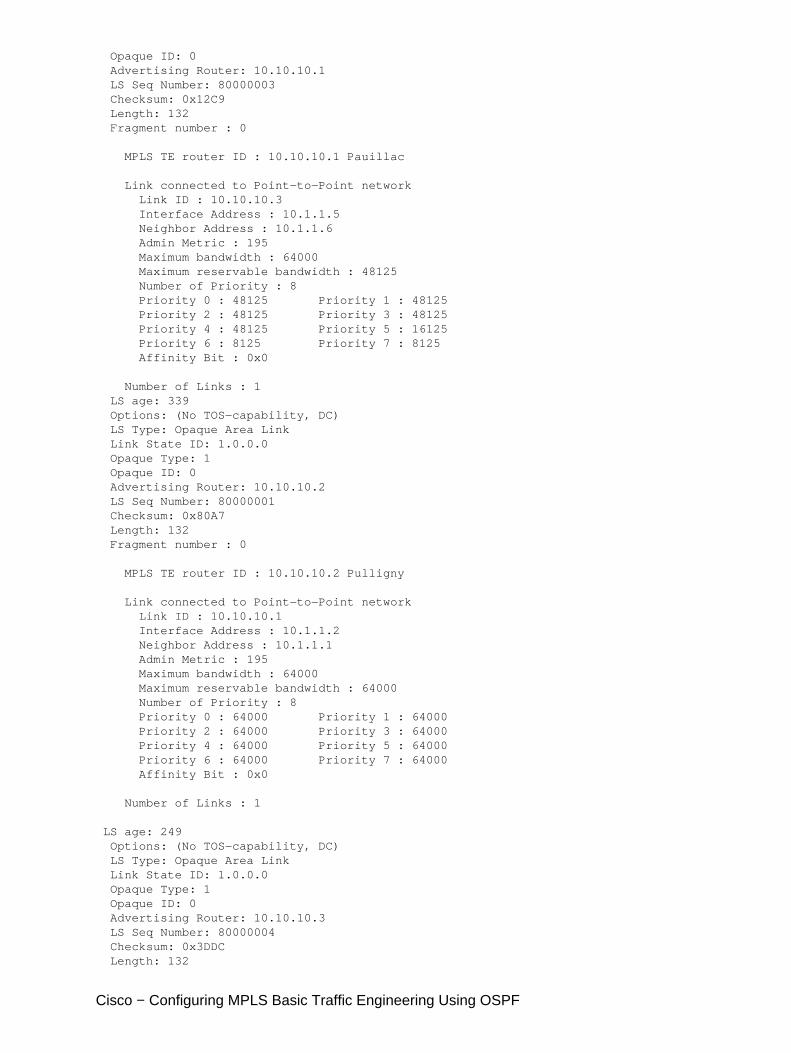
The show ip ospf database command can be restrained to Type 10 LSAs and shows the database that is usedby the MPLS TE process to calculate the best route (for TE) for dynamic tunnels (Pescara_t1 and Pescara_t3in this example). This can be seen in the following partial output:
Pesaro# show ip ospf database opaque−area
OSPF Router with ID (10.10.10.61) (Process ID 9)
Type−10 Opaque Link Area Link States (Area 9)
LS age: 397 Options: (No TOS−capability, DC) LS Type: Opaque Area Link Link State ID: 1.0.0.0 Opaque Type: 1
Cisco − Configuring MPLS Basic Traffic Engineering Using OSPF
Opaque ID: 0 Advertising Router: 10.10.10.1 LS Seq Number: 80000003 Checksum: 0x12C9 Length: 132 Fragment number : 0
MPLS TE router ID : 10.10.10.1 Pauillac
Link connected to Point−to−Point network Link ID : 10.10.10.3 Interface Address : 10.1.1.5 Neighbor Address : 10.1.1.6 Admin Metric : 195 Maximum bandwidth : 64000 Maximum reservable bandwidth : 48125 Number of Priority : 8 Priority 0 : 48125 Priority 1 : 48125 Priority 2 : 48125 Priority 3 : 48125 Priority 4 : 48125 Priority 5 : 16125 Priority 6 : 8125 Priority 7 : 8125 Affinity Bit : 0x0
Number of Links : 1 LS age: 339 Options: (No TOS−capability, DC) LS Type: Opaque Area Link Link State ID: 1.0.0.0 Opaque Type: 1 Opaque ID: 0 Advertising Router: 10.10.10.2 LS Seq Number: 80000001 Checksum: 0x80A7 Length: 132 Fragment number : 0
MPLS TE router ID : 10.10.10.2 Pulligny
Link connected to Point−to−Point network Link ID : 10.10.10.1 Interface Address : 10.1.1.2 Neighbor Address : 10.1.1.1 Admin Metric : 195 Maximum bandwidth : 64000 Maximum reservable bandwidth : 64000 Number of Priority : 8 Priority 0 : 64000 Priority 1 : 64000 Priority 2 : 64000 Priority 3 : 64000 Priority 4 : 64000 Priority 5 : 64000 Priority 6 : 64000 Priority 7 : 64000 Affinity Bit : 0x0
Number of Links : 1
LS age: 249 Options: (No TOS−capability, DC) LS Type: Opaque Area Link Link State ID: 1.0.0.0 Opaque Type: 1 Opaque ID: 0 Advertising Router: 10.10.10.3 LS Seq Number: 80000004 Checksum: 0x3DDC Length: 132
Cisco − Configuring MPLS Basic Traffic Engineering Using OSPF
Fragment number : 0
Related Information
MPLS Support Page• IP Routing Support Pages• Technical Support − Cisco Systems•