Configuring NAS-Initiated Dial-In VPDN Tunneling Network access server (NAS)-initiated dial-in tunneling provides secure tunneling of a PPP session from a NAS to a tunnel server without any special knowledge or interaction required from the client. • Finding Feature Information, page 1 • Prerequisites for Configuring NAS-Initiated Dial-In VPDN Tunneling, page 1 • Information About NAS-Initiated Dial-In VPDN Tunneling, page 2 • How to Configure NAS-Initiated Dial-In VPDN Tunneling, page 4 • Configuration Examples for NAS-Initiated Dial-In VPDN Tunneling, page 19 • Where to Go Next, page 23 • Additional References, page 23 • Feature Information for NAS-Initiated Dial-In VPDN Tunneling, page 25 Finding Feature Information Your software release may not support all the features documented in this module. For the latest caveats and feature information, see Bug Search Tool and the release notes for your platform and software release. To find information about the features documented in this module, and to see a list of the releases in which each feature is supported, see the feature information table at the end of this module. Use Cisco Feature Navigator to find information about platform support and Cisco software image support. To access Cisco Feature Navigator, go to www.cisco.com/go/cfn. An account on Cisco.com is not required. Prerequisites for Configuring NAS-Initiated Dial-In VPDN Tunneling • Before performing the tasks documented in this module, you must perform the required tasks in the Configuring AAA for VPDNs module. VPDN Configuration Guide, Cisco IOS Release 15M&T 1
Transcript
Configuring NAS-Initiated Dial-In VPDNTunneling
Network access server (NAS)-initiated dial-in tunneling provides secure tunneling of a PPP session from aNAS to a tunnel server without any special knowledge or interaction required from the client.
• Finding Feature Information, page 1
• Prerequisites for Configuring NAS-Initiated Dial-In VPDN Tunneling, page 1
• Information About NAS-Initiated Dial-In VPDN Tunneling, page 2
• How to Configure NAS-Initiated Dial-In VPDN Tunneling, page 4
• Configuration Examples for NAS-Initiated Dial-In VPDN Tunneling, page 19
• Where to Go Next, page 23
• Additional References, page 23
• Feature Information for NAS-Initiated Dial-In VPDN Tunneling, page 25
Finding Feature InformationYour software release may not support all the features documented in this module. For the latest caveats andfeature information, see Bug Search Tool and the release notes for your platform and software release. Tofind information about the features documented in this module, and to see a list of the releases in which eachfeature is supported, see the feature information table at the end of this module.
Use Cisco Feature Navigator to find information about platform support and Cisco software image support.To access Cisco Feature Navigator, go to www.cisco.com/go/cfn. An account on Cisco.com is not required.
Prerequisites for Configuring NAS-Initiated Dial-In VPDNTunneling
• Before performing the tasks documented in this module, you must perform the required tasks in theConfiguring AAA for VPDNs module.
• The NAS should be configured to receive incoming calls from clients using ISDN, the Public SwitchedTelephone Network (PSTN), Digital Subscriber Line (DSL), or cable modem .
Information About NAS-Initiated Dial-In VPDN Tunneling
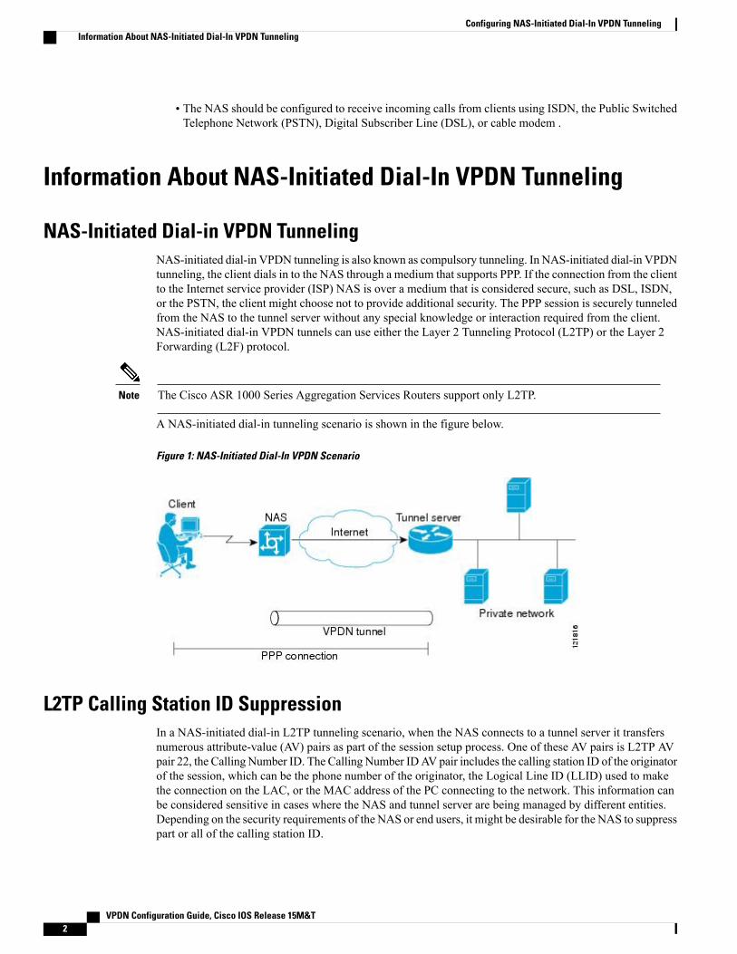
NAS-Initiated Dial-in VPDN TunnelingNAS-initiated dial-in VPDN tunneling is also known as compulsory tunneling. In NAS-initiated dial-in VPDNtunneling, the client dials in to the NAS through a medium that supports PPP. If the connection from the clientto the Internet service provider (ISP) NAS is over a medium that is considered secure, such as DSL, ISDN,or the PSTN, the client might choose not to provide additional security. The PPP session is securely tunneledfrom the NAS to the tunnel server without any special knowledge or interaction required from the client.NAS-initiated dial-in VPDN tunnels can use either the Layer 2 Tunneling Protocol (L2TP) or the Layer 2Forwarding (L2F) protocol.
The Cisco ASR 1000 Series Aggregation Services Routers support only L2TP.Note
A NAS-initiated dial-in tunneling scenario is shown in the figure below.
Figure 1: NAS-Initiated Dial-In VPDN Scenario
L2TP Calling Station ID SuppressionIn a NAS-initiated dial-in L2TP tunneling scenario, when the NAS connects to a tunnel server it transfersnumerous attribute-value (AV) pairs as part of the session setup process. One of these AV pairs is L2TP AVpair 22, the Calling Number ID. The Calling Number IDAV pair includes the calling station ID of the originatorof the session, which can be the phone number of the originator, the Logical Line ID (LLID) used to makethe connection on the LAC, or the MAC address of the PC connecting to the network. This information canbe considered sensitive in cases where the NAS and tunnel server are being managed by different entities.Depending on the security requirements of the NAS or end users, it might be desirable for the NAS to suppresspart or all of the calling station ID.
Configuring NAS-Initiated Dial-In VPDN TunnelingInformation About NAS-Initiated Dial-In VPDN Tunneling
Parts of the calling station ID can be masked, or the calling station ID can be removed completely. Callingstation ID suppression can be configured globally on the NAS, for individual VPDN groups on the NAS, oron the remote RADIUS server if one is configured.
L2TP FailoverIf a NAS fails to contact its peer during L2TP tunnel establishment, it can fail over to another configuredtunnel server and attempt tunnel establishment with that device.
Failover can occur in these scenarios:
• If the router sends a Start Control Connection Request (SCCRQ) a number of times and receives noresponse from the peer
• If the router receives a Stop Control Connection Notification (StopCCN) from its peer
• If the router receives a Call Disconnect Notify (CDN) message from its peer
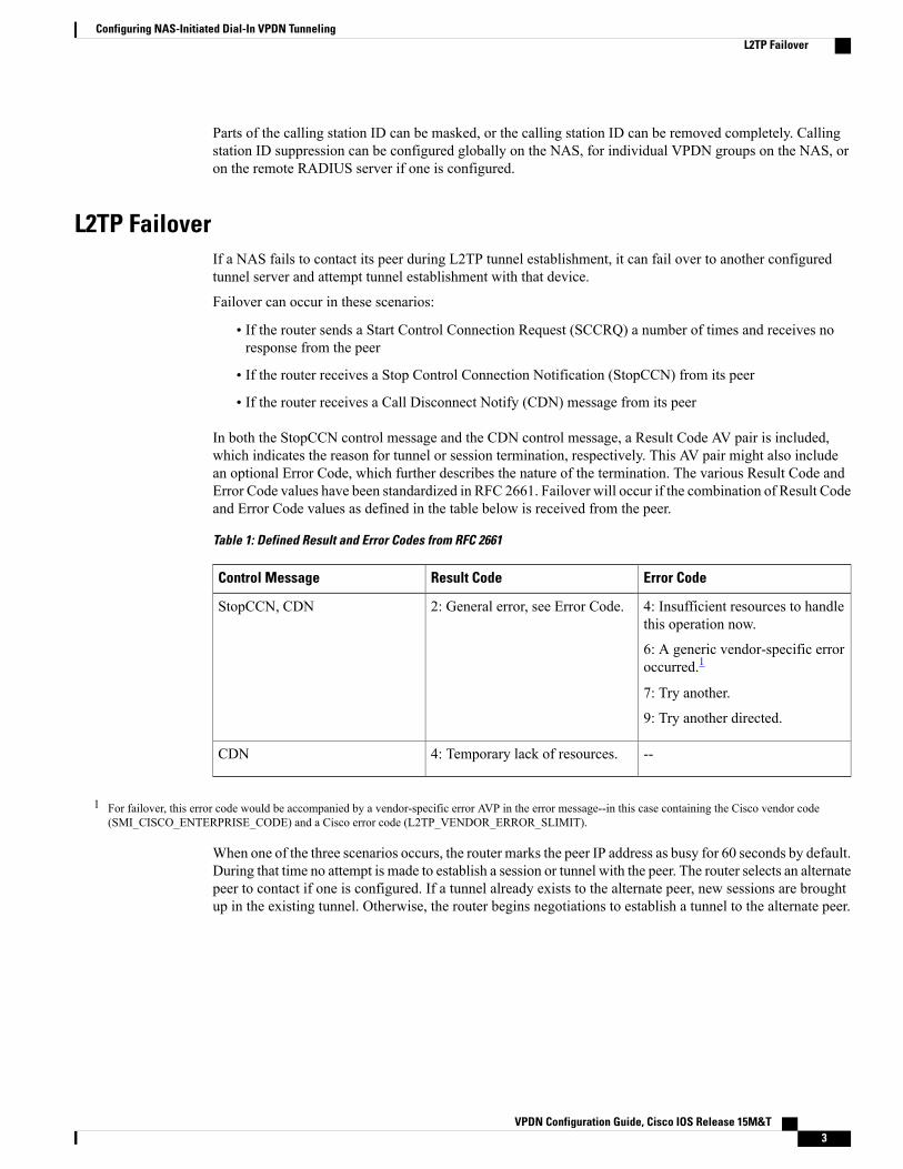
In both the StopCCN control message and the CDN control message, a Result Code AV pair is included,which indicates the reason for tunnel or session termination, respectively. This AV pair might also includean optional Error Code, which further describes the nature of the termination. The various Result Code andError Code values have been standardized in RFC 2661. Failover will occur if the combination of Result Codeand Error Code values as defined in the table below is received from the peer.
Table 1: Defined Result and Error Codes from RFC 2661
Error CodeResult CodeControl Message
4: Insufficient resources to handlethis operation now.
6: A generic vendor-specific erroroccurred.1
7: Try another.
9: Try another directed.
2: General error, see Error Code.StopCCN, CDN
--4: Temporary lack of resources.CDN
1 For failover, this error code would be accompanied by a vendor-specific error AVP in the error message--in this case containing the Cisco vendor code(SMI_CISCO_ENTERPRISE_CODE) and a Cisco error code (L2TP_VENDOR_ERROR_SLIMIT).
When one of the three scenarios occurs, the router marks the peer IP address as busy for 60 seconds by default.During that time no attempt is made to establish a session or tunnel with the peer. The router selects an alternatepeer to contact if one is configured. If a tunnel already exists to the alternate peer, new sessions are broughtup in the existing tunnel. Otherwise, the router begins negotiations to establish a tunnel to the alternate peer.
How to Configure NAS-Initiated Dial-In VPDN Tunneling
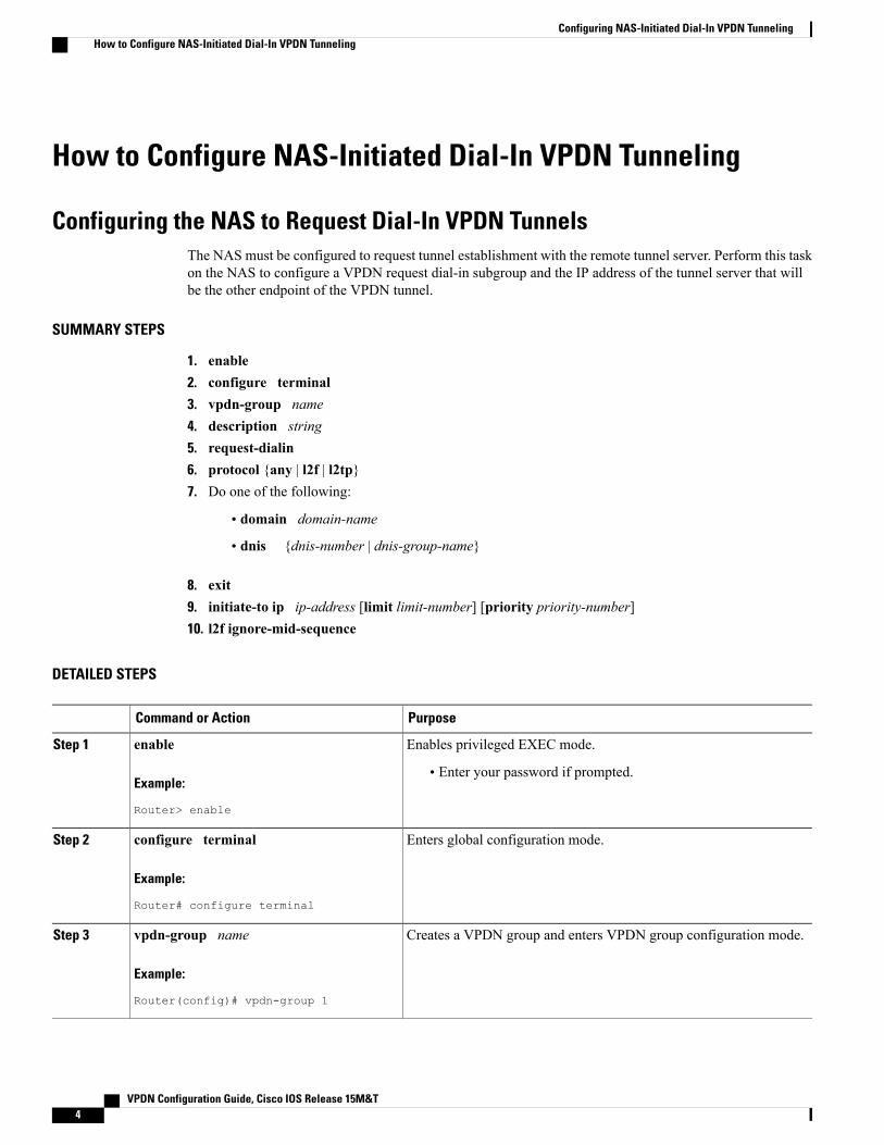
Configuring the NAS to Request Dial-In VPDN TunnelsThe NAS must be configured to request tunnel establishment with the remote tunnel server. Perform this taskon the NAS to configure a VPDN request dial-in subgroup and the IP address of the tunnel server that willbe the other endpoint of the VPDN tunnel.
SUMMARY STEPS
1. enable2. configure terminal3. vpdn-group name4. description string5. request-dialin6. protocol {any | l2f | l2tp}7. Do one of the following:
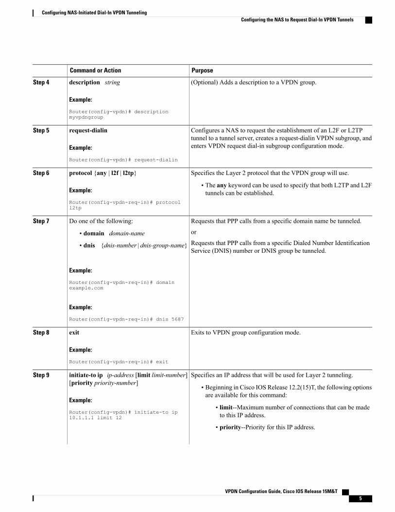
(Optional) Adds a description to a VPDN group.description string
Example:
Router(config-vpdn)# descriptionmyvpdngroup
Step 4
Configures a NAS to request the establishment of an L2F or L2TPtunnel to a tunnel server, creates a request-dialin VPDN subgroup, andenters VPDN request dial-in subgroup configuration mode.
request-dialin
Example:
Router(config-vpdn)# request-dialin
Step 5
Specifies the Layer 2 protocol that the VPDN group will use.protocol {any | l2f | l2tp}Step 6
Example:
Router(config-vpdn-req-in)# protocoll2tp
• The any keyword can be used to specify that both L2TP and L2Ftunnels can be established.
Requests that PPP calls from a specific domain name be tunneled.Do one of the following:Step 7
or• domain domain-nameRequests that PPP calls from a specific Dialed Number IdentificationService (DNIS) number or DNIS group be tunneled.
• dnis {dnis-number | dnis-group-name}
Example:
Router(config-vpdn-req-in)# domainexample.com
Example:
Router(config-vpdn-req-in)# dnis 5687
Exits to VPDN group configuration mode.exit
Example:
Router(config-vpdn-req-in)# exit
Step 8
Specifies an IP address that will be used for Layer 2 tunneling.initiate-to ip ip-address [limit limit-number][priority priority-number]
Step 9
• Beginning in Cisco IOS Release 12.2(15)T, the following optionsare available for this command:
Configuring NAS-Initiated Dial-In VPDN TunnelingConfiguring the NAS to Request Dial-In VPDN Tunnels
PurposeCommand or Action
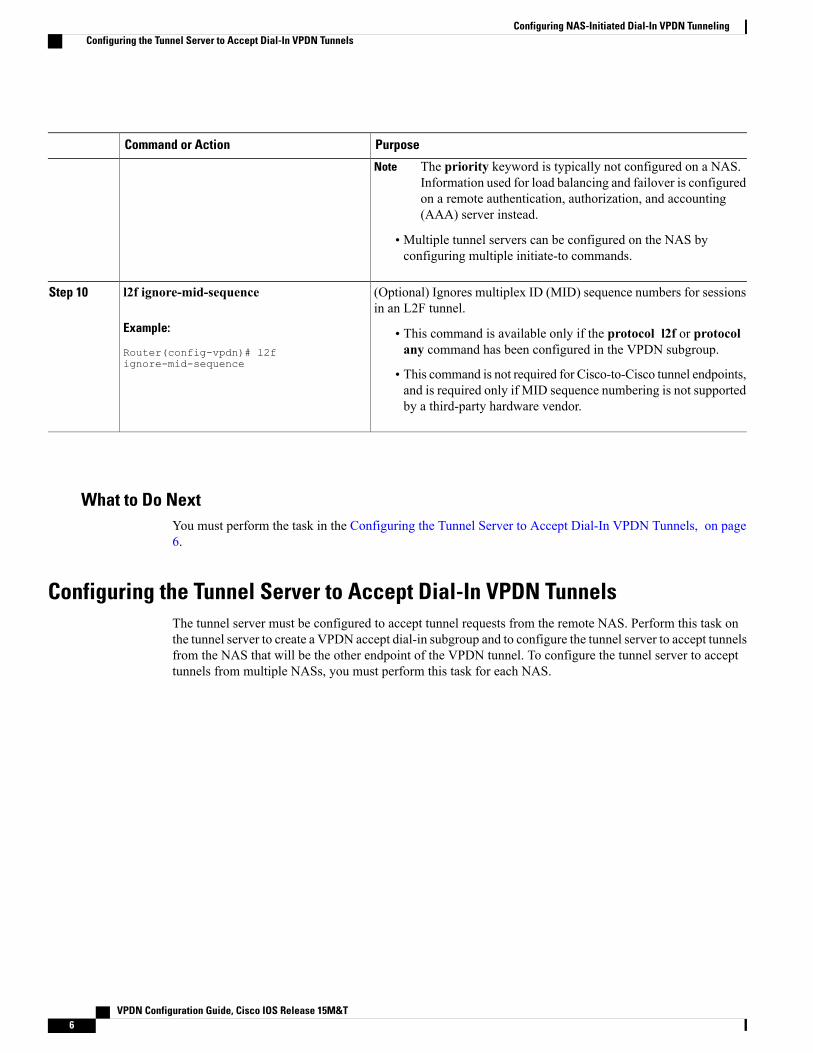
The priority keyword is typically not configured on a NAS.Information used for load balancing and failover is configuredon a remote authentication, authorization, and accounting(AAA) server instead.
Note
• Multiple tunnel servers can be configured on the NAS byconfiguring multiple initiate-to commands.
(Optional) Ignores multiplex ID (MID) sequence numbers for sessionsin an L2F tunnel.
l2f ignore-mid-sequence
Example:
Router(config-vpdn)# l2fignore-mid-sequence
Step 10
• This command is available only if the protocol l2f or protocolany command has been configured in the VPDN subgroup.
• This command is not required for Cisco-to-Cisco tunnel endpoints,and is required only if MID sequence numbering is not supportedby a third-party hardware vendor.
What to Do NextYou must perform the task in the Configuring the Tunnel Server to Accept Dial-In VPDN Tunnels, on page6.
Configuring the Tunnel Server to Accept Dial-In VPDN TunnelsThe tunnel server must be configured to accept tunnel requests from the remote NAS. Perform this task onthe tunnel server to create a VPDN accept dial-in subgroup and to configure the tunnel server to accept tunnelsfrom the NAS that will be the other endpoint of the VPDN tunnel. To configure the tunnel server to accepttunnels from multiple NASs, you must perform this task for each NAS.
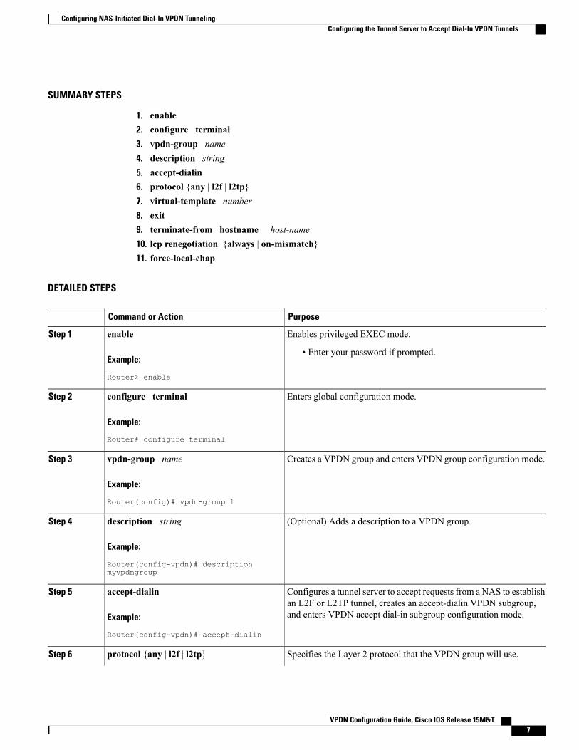
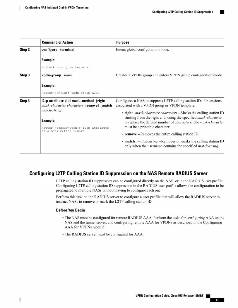
Enters global configuration mode.configure terminal
Example:
Router# configure terminal
Step 2
Creates a VPDN group and enters VPDN group configuration mode.vpdn-group name
Example:
Router(config)# vpdn-group 1
Step 3
(Optional) Adds a description to a VPDN group.description string
Example:
Router(config-vpdn)# descriptionmyvpdngroup
Step 4
Configures a tunnel server to accept requests from a NAS to establishan L2F or L2TP tunnel, creates an accept-dialin VPDN subgroup,and enters VPDN accept dial-in subgroup configuration mode.
accept-dialin
Example:
Router(config-vpdn)# accept-dialin
Step 5
Specifies the Layer 2 protocol that the VPDN group will use.protocol {any | l2f | l2tp}Step 6
Configuring NAS-Initiated Dial-In VPDN TunnelingConfiguring the Tunnel Server to Accept Dial-In VPDN Tunnels
PurposeCommand or Action
Example:
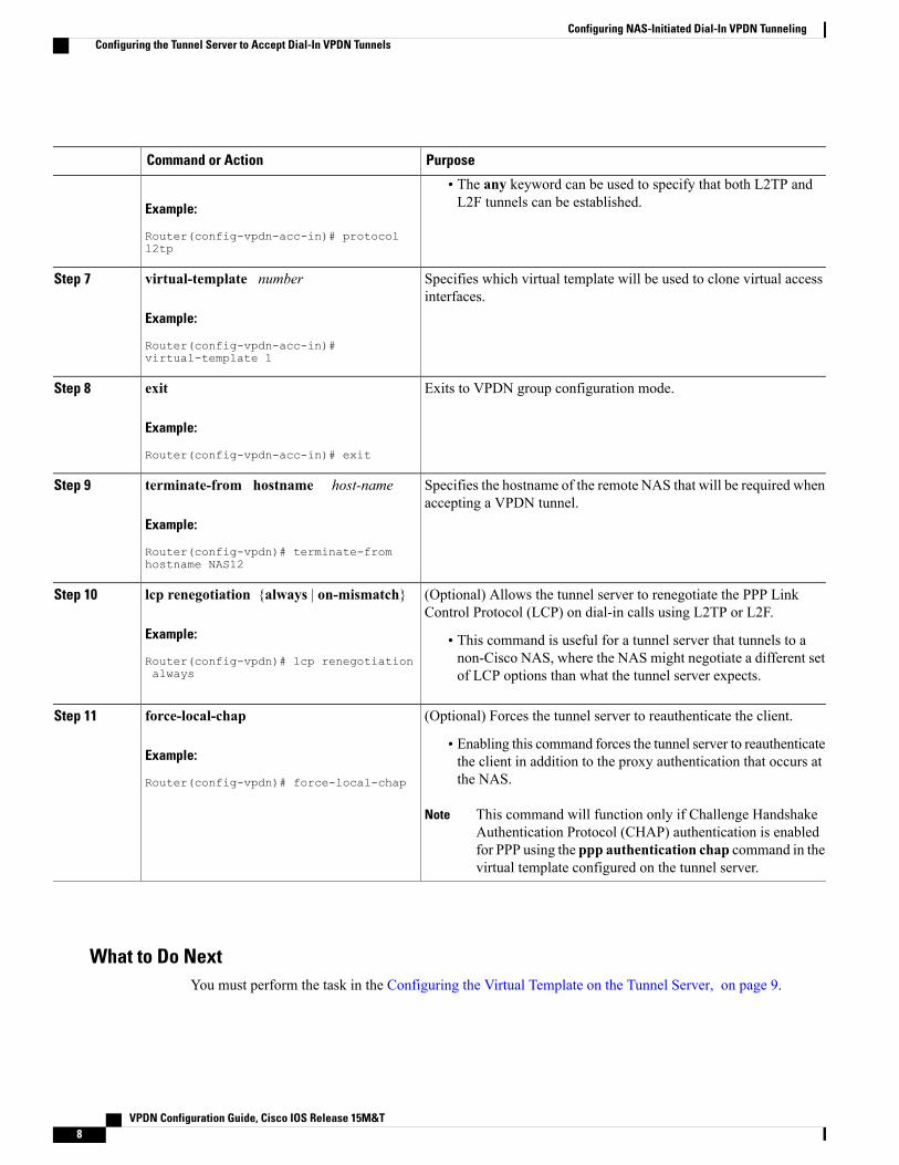
Router(config-vpdn-acc-in)# protocoll2tp
• The any keyword can be used to specify that both L2TP andL2F tunnels can be established.
Specifies which virtual template will be used to clone virtual accessinterfaces.
virtual-template number
Example:
Router(config-vpdn-acc-in)#virtual-template 1
Step 7
Exits to VPDN group configuration mode.exit
Example:
Router(config-vpdn-acc-in)# exit
Step 8
Specifies the hostname of the remote NAS that will be required whenaccepting a VPDN tunnel.
terminate-from hostname host-name
Example:
Router(config-vpdn)# terminate-fromhostname NAS12
Step 9
(Optional) Allows the tunnel server to renegotiate the PPP LinkControl Protocol (LCP) on dial-in calls using L2TP or L2F.
lcp renegotiation {always | on-mismatch}
Example:
Router(config-vpdn)# lcp renegotiationalways
Step 10
• This command is useful for a tunnel server that tunnels to anon-Cisco NAS, where the NAS might negotiate a different setof LCP options than what the tunnel server expects.
(Optional) Forces the tunnel server to reauthenticate the client.force-local-chapStep 11
Example:
Router(config-vpdn)# force-local-chap
• Enabling this command forces the tunnel server to reauthenticatethe client in addition to the proxy authentication that occurs atthe NAS.
This command will function only if Challenge HandshakeAuthentication Protocol (CHAP) authentication is enabledfor PPP using the ppp authentication chap command in thevirtual template configured on the tunnel server.
Note
What to Do NextYou must perform the task in the Configuring the Virtual Template on the Tunnel Server, on page 9.
Configuring NAS-Initiated Dial-In VPDN TunnelingConfiguring the Tunnel Server to Accept Dial-In VPDN Tunnels
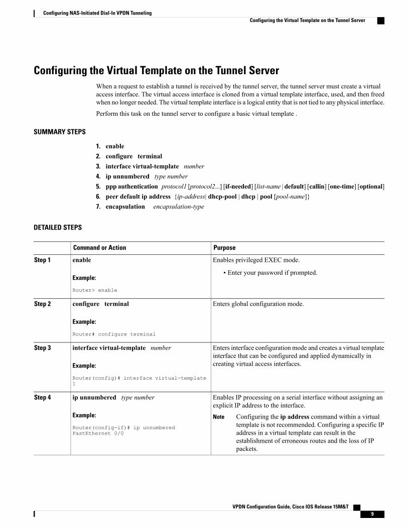
Configuring the Virtual Template on the Tunnel ServerWhen a request to establish a tunnel is received by the tunnel server, the tunnel server must create a virtualaccess interface. The virtual access interface is cloned from a virtual template interface, used, and then freedwhen no longer needed. The virtual template interface is a logical entity that is not tied to any physical interface.
Perform this task on the tunnel server to configure a basic virtual template .
SUMMARY STEPS
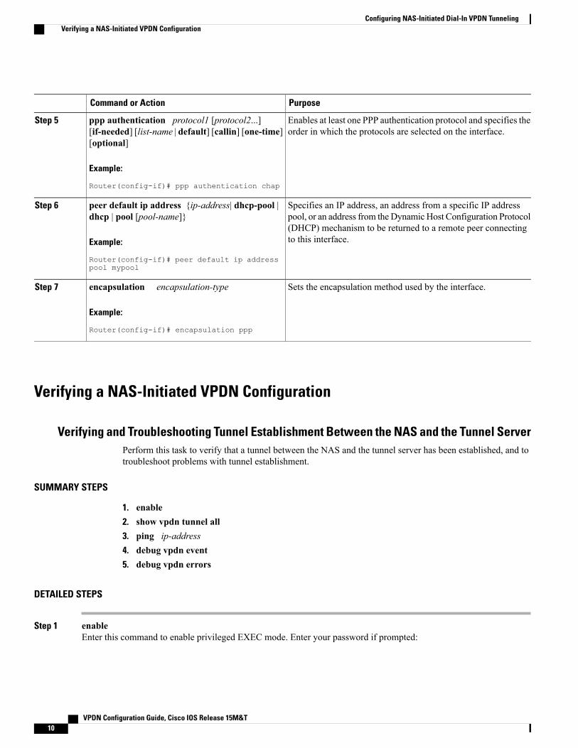
1. enable2. configure terminal3. interface virtual-template number4. ip unnumbered type number5. ppp authentication protocol1 [protocol2...] [if-needed] [list-name | default] [callin] [one-time] [optional]6. peer default ip address {ip-address| dhcp-pool | dhcp | pool [pool-name]}7. encapsulation encapsulation-type
DETAILED STEPS
PurposeCommand or Action
Enables privileged EXEC mode.enableStep 1
Example:
Router> enable
• Enter your password if prompted.
Enters global configuration mode.configure terminal
Example:
Router# configure terminal
Step 2
Enters interface configuration mode and creates a virtual templateinterface that can be configured and applied dynamically increating virtual access interfaces.
interface virtual-template number
Example:
Router(config)# interface virtual-template1
Step 3
Enables IP processing on a serial interface without assigning anexplicit IP address to the interface.
ip unnumbered type number
Example:
Router(config-if)# ip unnumberedFastEthernet 0/0
Step 4
Configuring the ip address command within a virtualtemplate is not recommended. Configuring a specific IPaddress in a virtual template can result in theestablishment of erroneous routes and the loss of IPpackets.
Specifies an IP address, an address from a specific IP addresspool, or an address from the Dynamic Host Configuration Protocol
peer default ip address {ip-address| dhcp-pool |dhcp | pool [pool-name]}
Step 6
(DHCP) mechanism to be returned to a remote peer connectingto this interface.Example:
Router(config-if)# peer default ip addresspool mypool
Sets the encapsulation method used by the interface.encapsulation encapsulation-type
Example:
Router(config-if)# encapsulation ppp
Step 7
Verifying a NAS-Initiated VPDN Configuration
Verifying and Troubleshooting Tunnel Establishment Between the NAS and the Tunnel ServerPerform this task to verify that a tunnel between the NAS and the tunnel server has been established, and totroubleshoot problems with tunnel establishment.
Configuring NAS-Initiated Dial-In VPDN TunnelingVerifying a NAS-Initiated VPDN Configuration
Example:
Router> enable
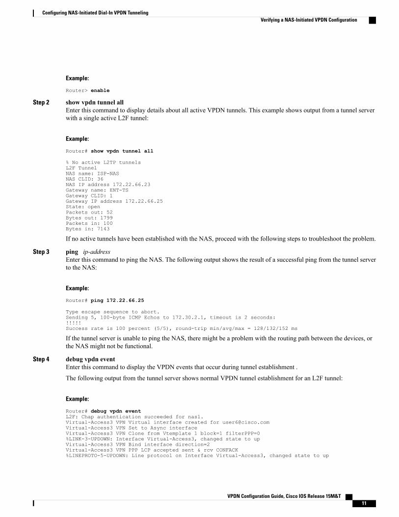
Step 2 show vpdn tunnel allEnter this command to display details about all active VPDN tunnels. This example shows output from a tunnel serverwith a single active L2F tunnel:
Example:
Router# show vpdn tunnel all
% No active L2TP tunnelsL2F TunnelNAS name: ISP-NASNAS CLID: 36NAS IP address 172.22.66.23Gateway name: ENT-TSGateway CLID: 1Gateway IP address 172.22.66.25State: openPackets out: 52Bytes out: 1799Packets in: 100Bytes in: 7143
If no active tunnels have been established with the NAS, proceed with the following steps to troubleshoot the problem.
Step 3 ping ip-addressEnter this command to ping the NAS. The following output shows the result of a successful ping from the tunnel serverto the NAS:
Example:
Router# ping 172.22.66.25
Type escape sequence to abort.Sending 5, 100-byte ICMP Echos to 172.30.2.1, timeout is 2 seconds:!!!!!Success rate is 100 percent (5/5), round-trip min/avg/max = 128/132/152 ms
If the tunnel server is unable to ping the NAS, there might be a problem with the routing path between the devices, orthe NAS might not be functional.
Step 4 debug vpdn eventEnter this command to display the VPDN events that occur during tunnel establishment .
The following output from the tunnel server shows normal VPDN tunnel establishment for an L2F tunnel:
Example:
Router# debug vpdn eventL2F: Chap authentication succeeded for nas1.Virtual-Access3 VPN Virtual interface created for [email protected] VPN Set to Async interfaceVirtual-Access3 VPN Clone from Vtemplate 1 block=1 filterPPP=0%LINK-3-UPDOWN: Interface Virtual-Access3, changed state to upVirtual-Access3 VPN Bind interface direction=2Virtual-Access3 VPN PPP LCP accepted sent & rcv CONFACK%LINEPROTO-5-UPDOWN: Line protocol on Interface Virtual-Access3, changed state to up
Configuring NAS-Initiated Dial-In VPDN TunnelingVerifying a NAS-Initiated VPDN Configuration
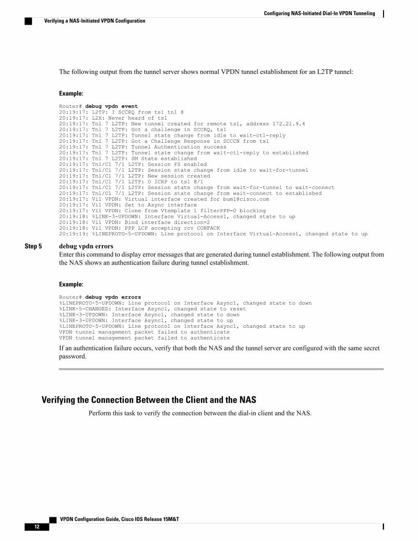
The following output from the tunnel server shows normal VPDN tunnel establishment for an L2TP tunnel:
Example:
Router# debug vpdn event20:19:17: L2TP: I SCCRQ from ts1 tnl 820:19:17: L2X: Never heard of ts120:19:17: Tnl 7 L2TP: New tunnel created for remote ts1, address 172.21.9.420:19:17: Tnl 7 L2TP: Got a challenge in SCCRQ, ts120:19:17: Tnl 7 L2TP: Tunnel state change from idle to wait-ctl-reply20:19:17: Tnl 7 L2TP: Got a Challenge Response in SCCCN from ts120:19:17: Tnl 7 L2TP: Tunnel Authentication success20:19:17: Tnl 7 L2TP: Tunnel state change from wait-ctl-reply to established20:19:17: Tnl 7 L2TP: SM State established20:19:17: Tnl/Cl 7/1 L2TP: Session FS enabled20:19:17: Tnl/Cl 7/1 L2TP: Session state change from idle to wait-for-tunnel20:19:17: Tnl/Cl 7/1 L2TP: New session created20:19:17: Tnl/Cl 7/1 L2TP: O ICRP to ts1 8/120:19:17: Tnl/Cl 7/1 L2TP: Session state change from wait-for-tunnel to wait-connect20:19:17: Tnl/Cl 7/1 L2TP: Session state change from wait-connect to established20:19:17: Vi1 VPDN: Virtual interface created for [email protected]:19:17: Vi1 VPDN: Set to Async interface20:19:17: Vi1 VPDN: Clone from Vtemplate 1 filterPPP=0 blocking20:19:18: %LINK-3-UPDOWN: Interface Virtual-Access1, changed state to up20:19:18: Vi1 VPDN: Bind interface direction=220:19:18: Vi1 VPDN: PPP LCP accepting rcv CONFACK20:19:19: %LINEPROTO-5-UPDOWN: Line protocol on Interface Virtual-Access1, changed state to up
Step 5 debug vpdn errorsEnter this command to display error messages that are generated during tunnel establishment. The following output fromthe NAS shows an authentication failure during tunnel establishment.
Example:
Router# debug vpdn errors%LINEPROTO-5-UPDOWN: Line protocol on Interface Async1, changed state to down%LINK-5-CHANGED: Interface Async1, changed state to reset%LINK-3-UPDOWN: Interface Async1, changed state to down%LINK-3-UPDOWN: Interface Async1, changed state to up%LINEPROTO-5-UPDOWN: Line protocol on Interface Async1, changed state to upVPDN tunnel management packet failed to authenticateVPDN tunnel management packet failed to authenticate
If an authentication failure occurs, verify that both the NAS and the tunnel server are configured with the same secretpassword.
Verifying the Connection Between the Client and the NASPerform this task to verify the connection between the dial-in client and the NAS.
Configuring NAS-Initiated Dial-In VPDN TunnelingVerifying a NAS-Initiated VPDN Configuration
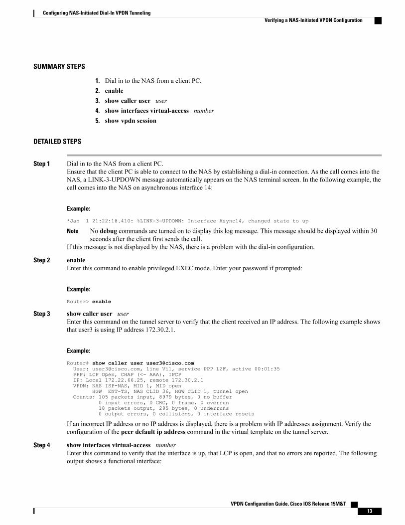
SUMMARY STEPS
1. Dial in to the NAS from a client PC.2. enable3. show caller user user4. show interfaces virtual-access number5. show vpdn session
DETAILED STEPS
Step 1 Dial in to the NAS from a client PC.Ensure that the client PC is able to connect to the NAS by establishing a dial-in connection. As the call comes into theNAS, a LINK-3-UPDOWN message automatically appears on the NAS terminal screen. In the following example, thecall comes into the NAS on asynchronous interface 14:
Example:
*Jan 1 21:22:18.410: %LINK-3-UPDOWN: Interface Async14, changed state to up
No debug commands are turned on to display this log message. This message should be displayed within 30seconds after the client first sends the call.
Note
If this message is not displayed by the NAS, there is a problem with the dial-in configuration.
Step 2 enableEnter this command to enable privileged EXEC mode. Enter your password if prompted:
Example:
Router> enable
Step 3 show caller user userEnter this command on the tunnel server to verify that the client received an IP address. The following example showsthat user3 is using IP address 172.30.2.1.
Example:
Router# show caller user [email protected]: [email protected], line Vi1, service PPP L2F, active 00:01:35PPP: LCP Open, CHAP (<- AAA), IPCPIP: Local 172.22.66.25, remote 172.30.2.1VPDN: NAS ISP-NAS, MID 1, MID open
HGW ENT-TS, NAS CLID 36, HGW CLID 1, tunnel openCounts: 105 packets input, 8979 bytes, 0 no buffer
If an incorrect IP address or no IP address is displayed, there is a problem with IP addresses assignment. Verify theconfiguration of the peer default ip address command in the virtual template on the tunnel server.
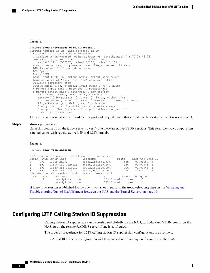
Step 4 show interfaces virtual-access numberEnter this command to verify that the interface is up, that LCP is open, and that no errors are reported. The followingoutput shows a functional interface:
Configuring NAS-Initiated Dial-In VPDN TunnelingVerifying a NAS-Initiated VPDN Configuration
Example:
Router# show interfaces virtual-access 1Virtual-Access1 is up, line protocol is upHardware is Virtual Access interfaceInterface is unnumbered. Using address of FastEthernet0/0 (172.22.66.25)MTU 1500 bytes, BW 115 Kbit, DLY 100000 usec,
reliablility 255/255, txload 1/255, rxload 1/255Encapsulation PPP, loopback not set, keepalive set (10 sec)DTR is pulsed for 5 seconds on resetLCP OpenOpen: IPCPLast input 00:00:02, output never, output hang neverLast clearing of "show interface" counters 3d00hQueueing strategy: fifoOutput queue 1/40, 0 drops; input queue 0/75, 0 drops5 minute input rate 0 bits/sec, 0 packets/sec5 minute output rate 0 bits/sec, 0 packets/sec
The virtual access interface is up and the line protocol is up, showing that virtual interface establishment was successful.
Step 5 show vpdn sessionEnter this command on the tunnel server to verify that there are active VPDN sessions. This example shows output froma tunnel server with several active L2F and L2TP tunnels.
Example:
Router# show vpdn session
L2TP Session Information Total tunnels 1 sessions 4LocID RemID TunID Intf Username State Last Chg Uniq ID4 691 13695 Se0/0 [email protected] est 00:06:00 45 692 13695 SSS Circuit [email protected] est 00:01:43 86 693 13695 SSS Circuit [email protected] est 00:01:43 93 690 13695 SSS Circuit [email protected] est 2d21h 3L2F Session Information Total tunnels 1 sessions 2CLID MID Username Intf State Uniq ID1 2 [email protected] SSS Circuit open 101 3 [email protected] SSS Circuit open 11
If there is no session established for the client, you should perform the troubleshooting steps in the Verifying andTroubleshooting Tunnel Establishment Between the NAS and the Tunnel Server, on page 10.
Configuring L2TP Calling Station ID SuppressionCalling station ID suppression can be configured globally on the NAS, for individual VPDN groups on theNAS, or on the remote RADIUS server if one is configured.
The order of precedence for L2TP calling station ID suppression configurations is as follows:
• A RADIUS server configuration will take precedence over any configuration on the NAS.
Configuring NAS-Initiated Dial-In VPDN TunnelingConfiguring L2TP Calling Station ID Suppression
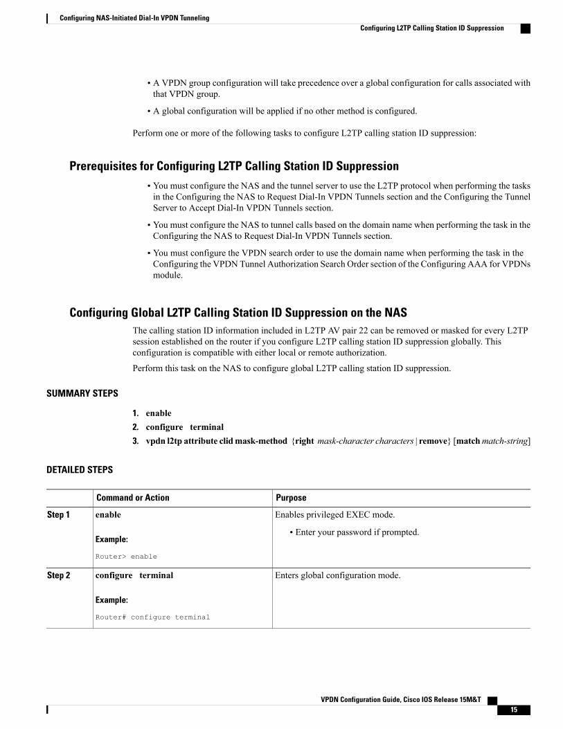
• A VPDN group configuration will take precedence over a global configuration for calls associated withthat VPDN group.
• A global configuration will be applied if no other method is configured.
Perform one or more of the following tasks to configure L2TP calling station ID suppression:
Prerequisites for Configuring L2TP Calling Station ID Suppression• You must configure the NAS and the tunnel server to use the L2TP protocol when performing the tasksin the Configuring the NAS to Request Dial-In VPDN Tunnels section and the Configuring the TunnelServer to Accept Dial-In VPDN Tunnels section.
• You must configure the NAS to tunnel calls based on the domain name when performing the task in theConfiguring the NAS to Request Dial-In VPDN Tunnels section.
• You must configure the VPDN search order to use the domain name when performing the task in theConfiguring the VPDN Tunnel Authorization Search Order section of the Configuring AAA for VPDNsmodule.
Configuring Global L2TP Calling Station ID Suppression on the NASThe calling station ID information included in L2TP AV pair 22 can be removed or masked for every L2TPsession established on the router if you configure L2TP calling station ID suppression globally. Thisconfiguration is compatible with either local or remote authorization.
Perform this task on the NAS to configure global L2TP calling station ID suppression.
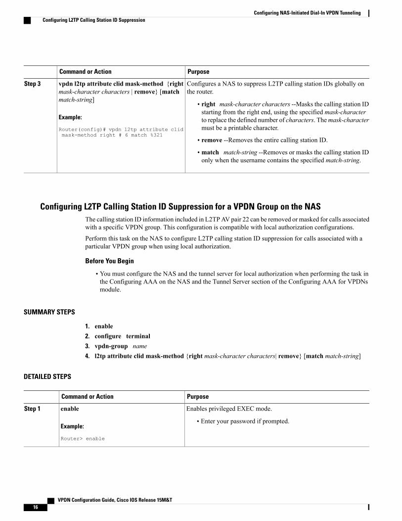
• right mask-character characters --Masks the calling station IDstarting from the right end, using the specified mask-character
Example:
Router(config)# vpdn l2tp attribute clidmask-method right # 6 match %321
to replace the defined number of characters. Themask-charactermust be a printable character.
• remove --Removes the entire calling station ID.
• match match-string --Removes or masks the calling station IDonly when the username contains the specified match-string.
Configuring L2TP Calling Station ID Suppression for a VPDN Group on the NASThe calling station ID information included in L2TPAV pair 22 can be removed or masked for calls associatedwith a specific VPDN group. This configuration is compatible with local authorization configurations.
Perform this task on the NAS to configure L2TP calling station ID suppression for calls associated with aparticular VPDN group when using local authorization.
Before You Begin
• You must configure the NAS and the tunnel server for local authorization when performing the task inthe Configuring AAA on the NAS and the Tunnel Server section of the Configuring AAA for VPDNsmodule.
to replace the defined number of characters. Themask-charactermust be a printable character.
• remove --Removes the entire calling station ID.
• match match-string --Removes or masks the calling station IDonly when the username contains the specified match-string.
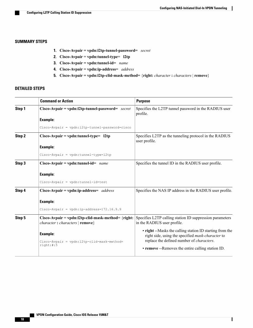
Configuring L2TP Calling Station ID Suppression on the NAS Remote RADIUS ServerL2TP calling station ID suppression can be configured directly on the NAS, or in the RADIUS user profile.Configuring L2TP calling station ID suppression in the RADIUS user profile allows the configuration to bepropagated to multiple NASs without having to configure each one.
Perform this task on the RADIUS server to configure a user profile that will allow the RADIUS server toinstruct NASs to remove or mask the L2TP calling station ID.
Before You Begin
• The NAS must be configured for remote RADIUS AAA. Perform the tasks for configuring AAA on theNAS and the tunnel server, and configuring remote AAA for VPDNs as described in the ConfiguringAAA for VPDNs module.
Configuring NAS-Initiated Dial-In VPDN TunnelingConfiguring L2TP Calling Station ID Suppression
Configuration Examples for NAS-Initiated Dial-In VPDNTunneling
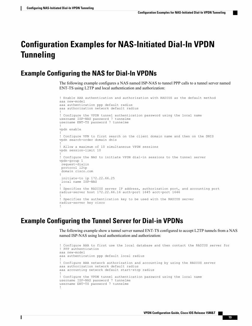
Example Configuring the NAS for Dial-In VPDNsThe following example configures a NAS named ISP-NAS to tunnel PPP calls to a tunnel server namedENT-TS using L2TP and local authentication and authorization:
! Enable AAA authentication and authorization with RADIUS as the default methodaaa new-modelaaa authentication ppp default radiusaaa authorization network default radius!! Configure the VPDN tunnel authentication password using the local nameusername ISP-NAS password 7 tunnelmeusername ENT-TS password 7 tunnelme!vpdn enable!! Configure VPN to first search on the client domain name and then on the DNISvpdn search-order domain dnis!! Allow a maximum of 10 simultaneous VPDN sessionsvpdn session-limit 10!! Configure the NAS to initiate VPDN dial-in sessions to the tunnel servervpdn-group 1request-dialinprotocol l2tpdomain cisco.com!initiate-to ip 172.22.66.25local name ISP-NAS!! Specifies the RADIUS server IP address, authorization port, and accounting portradius-server host 172.22.66.16 auth-port 1645 acct-port 1646!! Specifies the authentication key to be used with the RADIUS serverradius-server key cisco!
Example Configuring the Tunnel Server for Dial-in VPDNsThe following example show a tunnel server named ENT-TS configured to accept L2TP tunnels from a NASnamed ISP-NAS using local authentication and authorization:
! Configure AAA to first use the local database and then contact the RADIUS server for! PPP authenticationaaa new-modelaaa authentication ppp default local radius!! Configure AAA network authorization and accounting by using the RADIUS serveraaa authorization network default radiusaaa accounting network default start-stop radius!! Configure the VPDN tunnel authentication password using the local nameusername ISP-NAS password 7 tunnelmeusername ENT-TS password 7 tunnelme!
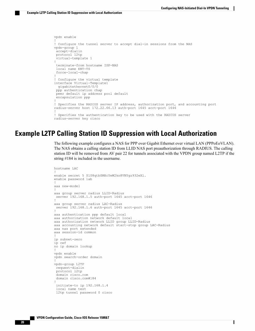
vpdn enable!! Configure the tunnel server to accept dial-in sessions from the NASvpdn-group 1accept-dialinprotocol l2tpvirtual-template 1!terminate-from hostname ISP-NASlocal name ENT-TSforce-local-chap!! Configure the virtual templateinterface Virtual-Template1gigabitethernet0/0/0ppp authentication chappeer default ip address pool defaultencapsulation ppp!! Specifies the RADIUS server IP address, authorization port, and accounting portradius-server host 172.22.66.13 auth-port 1645 acct-port 1646!! Specifies the authentication key to be used with the RADIUS serverradius-server key cisco
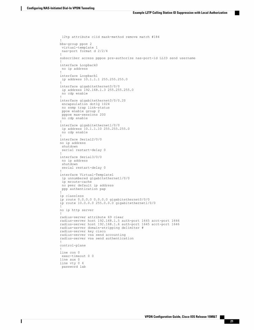
Example L2TP Calling Station ID Suppression with Local AuthorizationThe following example configures a NAS for PPP over Gigabit Ethernet over virtual LAN (PPPoEoVLAN).The NAS obtains a calling station ID from LLID NAS port preauthorization through RADIUS. The callingstation ID will be removed from AV pair 22 for tunnels associated with the VPDN group named L2TP if thestring #184 is included in the username.
hostname LAC!enable secret 5 $1$8qtb$MHcYeW2kn8VNYgz932eXl.enable password lab!aaa new-model!aaa group server radius LLID-Radiusserver 192.168.1.5 auth-port 1645 acct-port 1646!aaa group server radius LAC-Radiusserver 192.168.1.6 auth-port 1645 acct-port 1646!aaa authentication ppp default localaaa authorization network default localaaa authorization network LLID group LLID-Radiusaaa accounting network default start-stop group LAC-Radiusaaa nas port extendedaaa session-id common!ip subnet-zeroip cefno ip domain lookup!vpdn enablevpdn search-order domain!vpdn-group L2TPrequest-dialinprotocol l2tpdomain cisco.comdomain cisco.com#184!initiate-to ip 192.168.1.4local name testl2tp tunnel password 0 cisco
Configuring NAS-Initiated Dial-In VPDN TunnelingExample L2TP Calling Station ID Suppression with Local Authorization
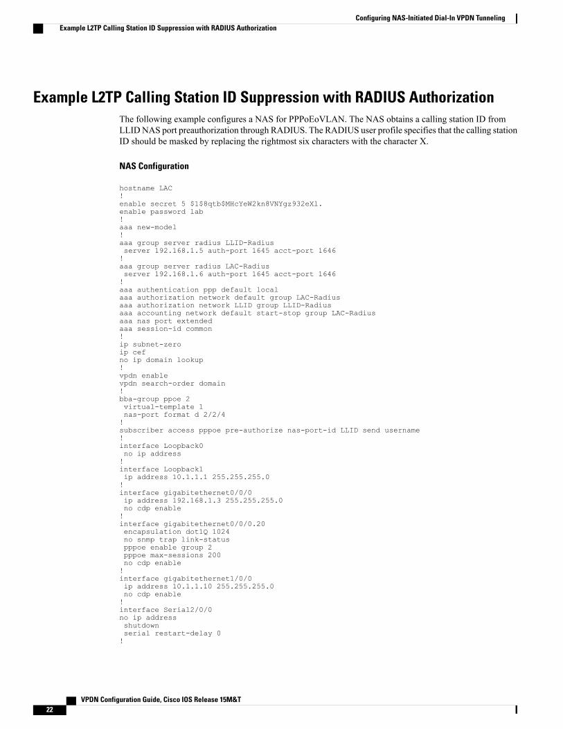
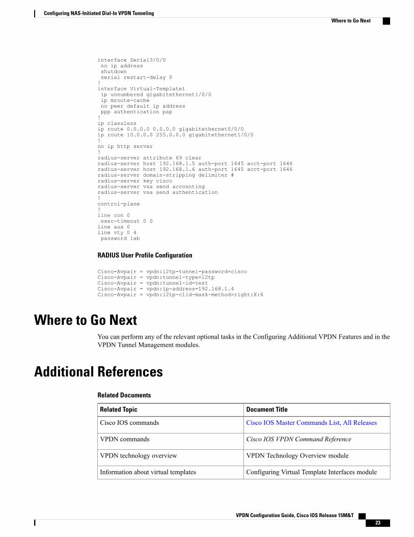
Example L2TP Calling Station ID Suppression with RADIUS AuthorizationThe following example configures a NAS for PPPoEoVLAN. The NAS obtains a calling station ID fromLLIDNAS port preauthorization through RADIUS. The RADIUS user profile specifies that the calling stationID should be masked by replacing the rightmost six characters with the character X.
NAS Configuration
hostname LAC!enable secret 5 $1$8qtb$MHcYeW2kn8VNYgz932eXl.enable password lab!aaa new-model!aaa group server radius LLID-Radiusserver 192.168.1.5 auth-port 1645 acct-port 1646!aaa group server radius LAC-Radiusserver 192.168.1.6 auth-port 1645 acct-port 1646!aaa authentication ppp default localaaa authorization network default group LAC-Radiusaaa authorization network LLID group LLID-Radiusaaa accounting network default start-stop group LAC-Radiusaaa nas port extendedaaa session-id common!ip subnet-zeroip cefno ip domain lookup!vpdn enablevpdn search-order domain!bba-group ppoe 2virtual-template 1nas-port format d 2/2/4!subscriber access pppoe pre-authorize nas-port-id LLID send username!interface Loopback0no ip address!interface Loopback1ip address 10.1.1.1 255.255.255.0!interface gigabitethernet0/0/0ip address 192.168.1.3 255.255.255.0no cdp enable!interface gigabitethernet0/0/0.20encapsulation dot1Q 1024no snmp trap link-statuspppoe enable group 2pppoe max-sessions 200no cdp enable!interface gigabitethernet1/0/0ip address 10.1.1.10 255.255.255.0no cdp enable!interface Serial2/0/0no ip addressshutdownserial restart-delay 0!
Where to Go NextYou can perform any of the relevant optional tasks in the Configuring Additional VPDN Features and in theVPDN Tunnel Management modules.
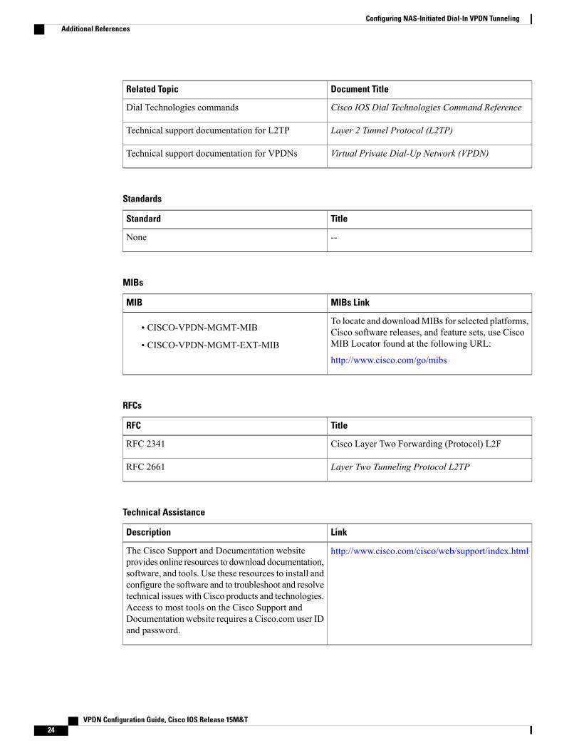
Additional ReferencesRelated Documents
Document TitleRelated Topic
Cisco IOS Master Commands List, All ReleasesCisco IOS commands
Layer 2 Tunnel Protocol (L2TP)Technical support documentation for L2TP
Virtual Private Dial-Up Network (VPDN)Technical support documentation for VPDNs
Standards
TitleStandard
--None
MIBs
MIBs LinkMIB
To locate and downloadMIBs for selected platforms,Cisco software releases, and feature sets, use CiscoMIB Locator found at the following URL:
http://www.cisco.com/go/mibs
• CISCO-VPDN-MGMT-MIB
• CISCO-VPDN-MGMT-EXT-MIB
RFCs
TitleRFC
Cisco Layer Two Forwarding (Protocol) L2FRFC 2341
Layer Two Tunneling Protocol L2TPRFC 2661
Technical Assistance
LinkDescription
http://www.cisco.com/cisco/web/support/index.htmlThe Cisco Support and Documentation websiteprovides online resources to download documentation,software, and tools. Use these resources to install andconfigure the software and to troubleshoot and resolvetechnical issues with Cisco products and technologies.Access to most tools on the Cisco Support andDocumentation website requires a Cisco.com user IDand password.
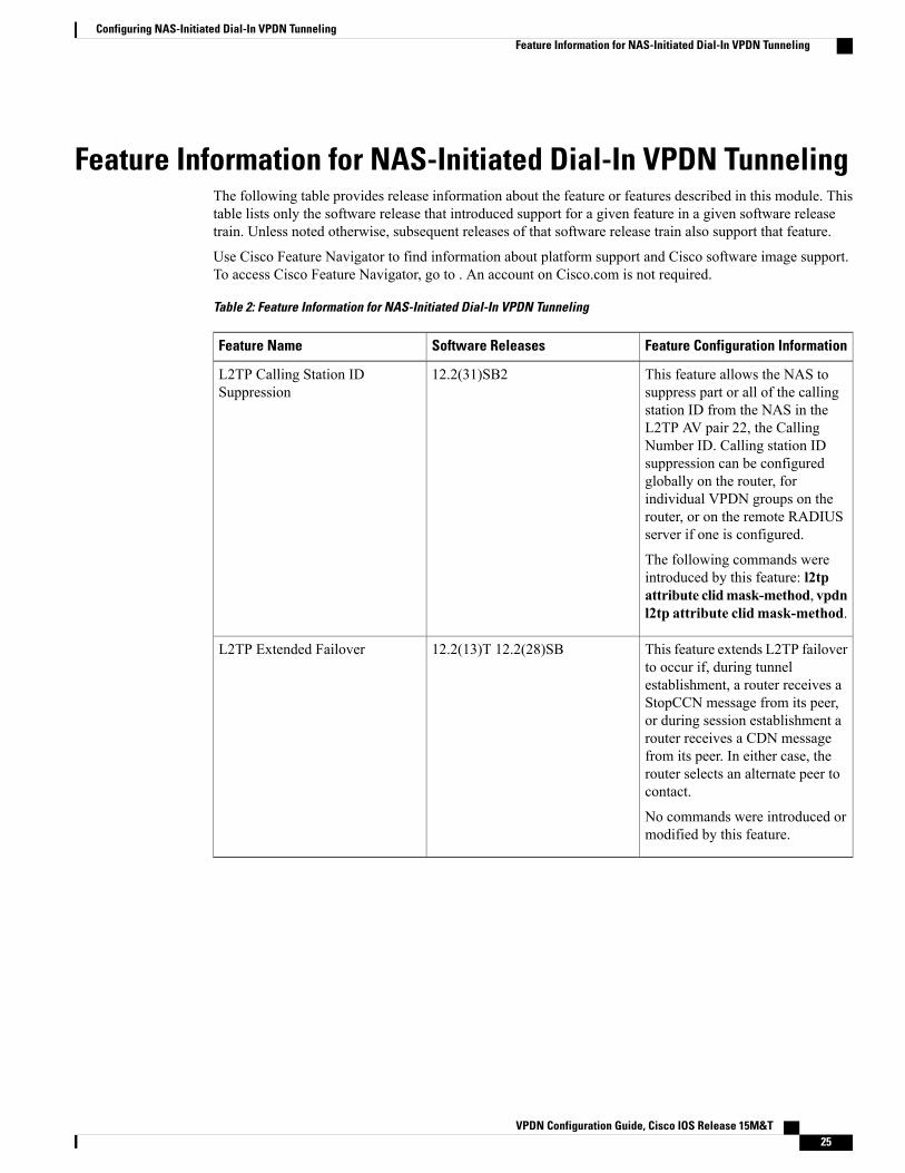
Feature Information for NAS-Initiated Dial-In VPDN TunnelingThe following table provides release information about the feature or features described in this module. Thistable lists only the software release that introduced support for a given feature in a given software releasetrain. Unless noted otherwise, subsequent releases of that software release train also support that feature.
Use Cisco Feature Navigator to find information about platform support and Cisco software image support.To access Cisco Feature Navigator, go to . An account on Cisco.com is not required.
Table 2: Feature Information for NAS-Initiated Dial-In VPDN Tunneling
Feature Configuration InformationSoftware ReleasesFeature Name
This feature allows the NAS tosuppress part or all of the callingstation ID from the NAS in theL2TP AV pair 22, the CallingNumber ID. Calling station IDsuppression can be configuredglobally on the router, forindividual VPDN groups on therouter, or on the remote RADIUSserver if one is configured.
The following commands wereintroduced by this feature: l2tpattribute clidmask-method, vpdnl2tp attribute clid mask-method.
12.2(31)SB2L2TP Calling Station IDSuppression
This feature extends L2TP failoverto occur if, during tunnelestablishment, a router receives aStopCCN message from its peer,or during session establishment arouter receives a CDN messagefrom its peer. In either case, therouter selects an alternate peer tocontact.
No commands were introduced ormodified by this feature.