180
Configuring Policy Services Setting up Quality of Service and Access Policies Third Edition December 2008 Oracle Communications IP Service Activator™ Version 5.2.4

Configuring PolicyServices
Setting up Quality of Service and Access PoliciesThird Edition
December 2008
Oracle Communications IP Service Activator™ Version 5.2.4
Copyright © 1997, 2008, Oracle. All rights reserved.
The Programs (which include both the software and documentation) contain proprietary information; they are provided under a license agreement containing restrictions on use and disclosure and are also protected by copyright, patent, and other intellectual and industrial property laws. Reverse engineering, disassembly, or decompilation of the Programs, except to the extent required to obtain interoperability with other independently created software or as specified by law, is prohibited.
The information contained in this document is subject to change without notice. If you find any problems in the documentation, please report them to us in writing. This document is not warranted to be error-free. Except as may be expressly permitted in your license agreement for these Programs, no part of these Programs may be reproduced or transmitted in any form or by any means, electronic or mechanical, for any purpose.
If the programs are delivered to the United States Government or anyone licensing or using the Programs on behalf of the United States Government, the following notice is applicable:
U.S. GOVERNMENT RIGHTS Programs, software, databases, and related documentation and technical data delivered to U.S. Government customers are "commercial computer software" or "commercial technical data" pursuant to the applicable Federal Acquisition Regulation and agency-specific supplemental regulations. As such, use, duplication, disclosure, modification, and adaptation of the Programs, including documentation and technical data, shall be subject to the licensing restrictions set forth in the applicable Oracle license agreement, and, to the extent applicable, the additional rights set forth in FAR 52.227-19, Commercial Computer Software--Restricted Rights (June 1987). Oracle USA, Inc., 500 Oracle Parkway, Redwood City, CA 94065.
The Programs are not intended for use in any nuclear, aviation, mass transit, medical, or other inherently dangerous applications. It shall be the licensee’s responsibility to take all appropriate fail-safe, backup, redundancy and other measures to ensure the safe use of such applications if the Programs are used for such purposes, and we disclaim liability for any damages caused by such use of the Programs.
The Programs may provide links to Web sites and access to content, products, and services from third parties. Oracle is not responsible for the availability of, or any content provided on, third-party Web sites. You bear all risks associated with the use of such content. If you choose to purchase any products or services from a third party, the relationship is directly between you and the third party. Oracle is not responsible for: (a) the quality of third-party products or services; or (b) fulfilling any of the terms of the agreement with the third party, including delivery of products or services and warranty obligations related to purchased products or services. Oracle is not responsible for any loss or damage of any sort that you may incur from dealing with any third party.
Oracle, JD Edwards, and PeopleSoft are registered trademarks of Oracle Corporation and/or its affiliates. Other names may be trademarks of their respective owners.

Configuring Policy Services – Third Edition Contents
Contents
Preface ................................................................................... ix
About this document ................................................................................. ix
Before contacting Oracle Global Customer Support (GCS) .............................. ix
Contacting Oracle Global Customer Support (GCS) ........................................ x
Downloading products and documentation .................................................... x
Downloading a media pack ................................................................... xi
Service Activator publications .................................................................... xi
............................................................................................................. xi
Chapter 1 Applying a QoS or Access Control Policy ........................... 1
Overview .................................................................................................2
Standard PHB and MQC PHB groups ........................................................3
Policy roles ...............................................................................................5
Using roles in policy elements ................................................................6
Policy inheritance ......................................................................................8
Before implementing a QoS or access control policy ..................................... 10
Set up basic data ............................................................................... 10
Check capabilities ............................................................................... 11
Set up and assign policy roles .............................................................. 11
Assign traffic to appropriate classes of service ........................................ 11
Consider where to apply policy elements ............................................... 12
Organizing QoS objects into user-defined folders .................................... 12
Classification Aggregation Control ......................................................... 12
Marking on Cisco routers ..................................................................... 20
QoS on Alcatel routers ........................................................................ 20
QoS on Juniper M-series routers ........................................................... 21
Implementing policy ................................................................................ 21
Abstract and concrete policy elements ....................................................... 22
Chapter 2 Setting Up Basic Policy Data ........................................... 25
Importing policy files ............................................................................... 26
Service Activator 5.2.4 iii

Contents Configuring Policy Services – Third Edition
Class of service data ................................................................................ 27
Packet markings ................................................................................ 28
Migrating from IP Precedence to DSCP .................................................. 35
Classes of Service .............................................................................. 35
802.1p user priority ............................................................................ 39
Policy components ................................................................................... 39
Setting up traffic types ........................................................................ 40
Setting up a compound traffic type ....................................................... 44
Setting up a traffic type group ............................................................. 45
Setting up a classification .................................................................... 46
Setting up a date and time template ..................................................... 53
Setting up IP protocols ........................................................................ 54
Setting up accounts ................................................................................. 54
Chapter 3 Defining QoS and Access Control .................................... 59
Introduction ........................................................................................... 60
Using roles in rules .................................................................................. 61
Rule support on an interface ..................................................................... 63
Rule support on devices ........................................................................... 64
Using roles in rules .................................................................................. 64
Classification rules ................................................................................... 64
Policing rules .......................................................................................... 68
Access rules ........................................................................................... 70
Using the ‘deny’ classification in Cisco ACLs ................................................ 71
Updating multiple rules ............................................................................ 73
Copying rules ......................................................................................... 75
Implementing rules ................................................................................. 76
Checking implemented rules ..................................................................... 76
Abstract and concrete rules ................................................................. 76
Rule status ........................................................................................ 76
Viewing implemented rules .................................................................. 77
If concrete rules are not created ........................................................... 84
Managing rules ....................................................................................... 84
iv Service Activator 5.2.4

Configuring Policy Services – Third Edition Contents
Changing the sequence order of rules ................................................... 84
How rule conflicts are avoided .............................................................. 85
Disabling rules ................................................................................... 86
Chapter 4 Defining Standard PHB Groups ....................................... 89
Introduction ........................................................................................... 90
MQC PHB groups ................................................................................ 90
Supported traffic shaping/queuing mechanisms ........................................... 91
Class of service mechanisms ................................................................ 91
VC traffic shaping mechanisms ............................................................. 91
Vendor support .................................................................................. 91
Class of service mechanism combinations .............................................. 92
Before setting up a standard PHB group ..................................................... 93
Selecting the queuing or traffic shaping mechanisms ............................... 93
Deciding where to apply the standard PHB groups .................................. 93
Using roles in PHB groups .................................................................... 94
Setting up a standard PHB group ............................................................... 95
Setting up Weighted Round Robin ......................................... 97
Setting up Priority Queuing .................................................................. 98
Setting up Rate Limiting ...................................................................... 99
Setting up Weighted Random Early Detection ....................................... 100
Setting up Weighted Fair Queuing ...................................................... 102
Setting up ATM traffic shaping ........................................................... 105
Setting up Frame Relay Traffic Shaping ............................................... 106
Chapter 5 Defining MQC PHB Groups ............................................ 111
Introduction ......................................................................................... 112
Supported traffic management mechanisms .............................................. 115
Before setting up an MQC PHB group ....................................................... 116
Deciding which QoS actions to select .................................................. 116
Defining Classes of Service ................................................................ 116
Check capabilities ............................................................................. 116
Deciding where to apply MQC PHB groups ............................................ 117
Service Activator 5.2.4 v

Contents Configuring Policy Services – Third Edition
Using roles in MQC PHB groups .......................................................... 117
Setting up an MQC PHB group ................................................................. 118
Specifying evaluation order ............................................................... 119
Setting up Low Latency Queuing ........................................................ 122
Setting up Class-Based Weighted Fair Queuing ..................................... 124
Setting up Class-Based Policing .......................................................... 125
Setting up Class-Based Shaping ......................................................... 131
Setting up Class-Based Marking ......................................................... 135
Setting up Congestion Avoidance ........................................................ 136
Nesting MQC PHB groups ................................................................... 138
RTP Header Compression .................................................................. 142
Chapter 6 Implementing and Managing PHB Groups ..................... 143
Implementing a PHB group ..................................................................... 144
Associating a PHB group with a policy target ........................................ 144
Committing the transaction ............................................................... 144
Checking implemented PHB groups .......................................................... 144
Abstract and concrete PHB groups ...................................................... 144
PHB group status ............................................................................. 145
Viewing implemented PHB groups ....................................................... 146
If concrete PHB groups are not created ............................................... 148
Managing PHB groups ............................................................................ 149
Changing the sequence order of PHB groups ........................................ 149
PHB Group map-class names ............................................................. 149
Manual specification of Cisco frame-relay map class names .................... 150
About Configuration Policies .................................................................... 151
Adding a new Configuration Policy ...................................................... 151
Chapter 7 Example Policy Setups .................................................. 153
Using roles to apply policy ...................................................................... 154
Requirements .................................................................................. 154
Solution .......................................................................................... 155
Applying policy to a VC endpoint ............................................................. 157
Using classifications in rules .................................................................... 159
vi Service Activator 5.2.4

Configuring Policy Services – Third Edition Contents
Copying Classification, Policing and Access rules ........................................ 161
Index ................................................................................... 163
Service Activator 5.2.4 vii

Contents Configuring Policy Services – Third Edition
viii Service Activator 5.2.4

Configuring Policy Services – Third Edition Preface
Preface
About this documentThe Configuring Policy Services guide explains how to configure quality of service (QoS) and access control policies. It is intended for network configuration engineers.
It consists of the following chapters:
Chapter 1: Applying a QoS or Access Control Policy introduces the Service Activator elements that can be used to define a QoS or access control and highlights some of the issues you need to consider when developing a policy.
Chapter 2: Setting Up Basic Policy Data describes how to set up the basic class of service data and rule component data that are necessary before implementing policies and services.
Chapter 3: Defining QoS and Access Control provides an overview of Service Activator’s rule types and describes how to implement and manage rules.
Chapter 4: Defining Standard PHB Groups describes the queuing and VC mechanisms that can be implemented with standard PHB groups and explains how to implement and manage standard PHB groups.
Chapter 5: Defining MQC PHB Groups describes Cisco’s Modular QoS Command Line Interface (MQC) mechanisms that can be implemented with MQC PHB groups and explains how to implement and manage MQC PHB groups.
Chapter 6: Implementing and Managing PHB Groups describes how to implement and manage PHB groups.
Chapter 7: Example Policy Setups provides some policy setup examples.
Before contacting Oracle Global Customer Support (GCS)
If you have an issue or question, Oracle recommends reviewing the product documentation and articles on MetaLink in the Top Technical Documents section to see if you can find a solution. MetaLink is located at http://metalink.oracle.com.
In addition to MetaLink, product documentation can also be found on the product CDs and in the product set on Oracle E-Delivery.
Service Activator 5.2.4 ix

Preface Configuring Policy Services – Third Edition
Within the product documentation, the following publications may contain problem resolutions, work-arounds and troubleshooting information:
— Release Notes
— Oracle Installation and User's Guide
— README files
Contacting Oracle Global Customer Support (GCS)You can submit, update, and review service requests (SRs) of all severities on MetaLink, which is available 24 hours a day, 7 days a week. For technical issues of an urgent nature, you may call Oracle Global Customer Support (GCS) directly.
Oracle prefers that you use MetaLink to log your SR electronically, but if you need to contact GCS by telephone regarding a new SR, a support engineer will take down the information about your technical issue and then assign the SR to a technical engineer. A technical support representative for the Oracle and/or former MetaSolv products will then contact you.
Note that logging a new SR in a language other than English is only supported during your local country business hours. Outside of your local country business hours, technical issues are supported in English only. All SRs not logged in English outside of your local country business hours will be received the next business day. For broader access to skilled technical support, Oracle recommends logging new SRs in English.
Oracle GCS can be reached locally in each country. Refer to the Oracle website for the support contact information in your country. The Oracle support website is located at http://www.oracle.com/support/contact.html.
Downloading products and documentationTo download the Oracle and/or former MetaSolv products and documentation, go to the Oracle E-Delivery site, located at http://edelivery.oracle.com.
You can purchase a hard copy of Oracle product documentation on the Oracle store site, located at http://oraclestore.oracle.com.
For a complete selection of Oracle documentation, go to the Oracle documentation site, located at http://www.oracle.com/technology/documentation.
x Service Activator 5.2.4

Configuring Policy Services – Third Edition Preface
Downloading a media pack
To download a media pack from Oracle E-Delivery
1. Go to http://edelivery.oracle.com.
2. Select the appropriate language and click Continue.
3. Enter the appropriate Export Validation information, accept the license agreements and click Continue.
4. For Product Pack, select Oracle Communications Applications.
5. For Platform, select the appropriate platform for your installation.
6. Click Go.
7. Select the appropriate media pack and click Continue.
8. Click Download for the items you wish to download.
9. Follow the installation documentation for each component you wish to install.
Service Activator publicationsThe Service Activator documentation suite includes a full range of publications. Refer to the Service Activator Release Notes for more information.
Service Activator 5.2.4 xi

Preface Configuring Policy Services – Third Edition
xii Service Activator 5.2.4

Configuring Policy Services – Third Edition Applying a QoS or Access Control Policy
Chapter 1
Applying a QoS or Access Control Policy
This chapter introduces the Service Activator elements that can be used to define a QoS or security policy and highlights some of the issues you need to consider. The chapter:
Outlines Service Activator’s rules, PHB groups and driver scripts
Describes the policy roles that enable you to group sets of devices and interfaces and so apply policy on a group by group basis
Explains how to use policy roles in the policy elements you define
Describes Service Activator’s policy inheritance model
Outlines the tasks involved in setting up a QoS or access control policy
Highlights some of the points you need to consider when setting up a QoS or security policy
Explains how to implement the QoS or access control policy and describes what happens when policy is propagated to the network
Describes Service Activator’s concept of abstract and concrete policy elements and explains how they appear in the user interface
Service Activator 5.2.4 1

Applying a QoS or Access Control Policy Configuring Policy Services – Third Edition
OverviewService Activator provides the following basic building blocks for creating a QoS or access control policy:
Policy rules – there are three rule types, each with a distinct function:
— Classification rules enable you to mark traffic and optionally manage bandwidth
— Policing rules police the bandwidth used by a particular traffic type and, optionally, re-mark traffic
— Access rules implement security by permitting or denying traffic
PHB groups allow QoS mechanisms to be applied to interfaces. There are two types of PHB groups:
— Standard PHB groups – allow you to implement QoS mechanisms
— MQC PHB groups – allow you to implement Modular QoS CLI mechanisms developed by Cisco to simplify the configuration of QoS on all device types
Driver scripts – enable you to make minor configuration changes by directly configuring a device
These basic building blocks are collectively referred to as policy elements.
Figure 1 illustrates how and where you might apply rules and standard PHB groups.
Service Activator provides an easily maintainable method for applying policy through a policy inheritance model and the concept of roles. The inheritance model enables policy defined at a high level, such as the domain or network, to be inherited to lower level objects, such as devices and interfaces. Roles enable you to group devices and interfaces by, for example, customer and service package, and create policy targeted at that group. Policy can be directed towards specific groups of devices and interfaces.
Rules, PHB groups and driver scripts can be applied to any policy target – that is, a customer, VPN or site, or a network component such as a device or interface. The configuration associated with a policy element is inherited through the inheritance model and applied at the relevant devices, interfaces, sub-interfaces or VC endpoints.
You can apply rules and PHB groups to domains but you cannot apply driver scripts at this level.
2 Service Activator 5.2.4

Configuring Policy Services – Third Edition Applying a QoS or Access Control Policy
To support the definition of rules, a range of rule components can be defined and used within any number of policy rules. A number of these components can be created by loading a set of example policy files.
For more information about rule components, see Setting Up Basic Policy Data on page 25. For information on loading example policy files into Service Activator, see Importing policy files on page 94.
Standard PHB and MQC PHB groupsStandard PHB (Per Hop Behavior) groups provide a method for implementing a QoS policy mechanism for traffic queuing and/or shaping on the interfaces of specific device types. The QoS mechanism that you select is applied to all of the classes of service associated with the standard PHB group. You can apply other QoS policies to the same interfaces using policing and classification rules. The Class of Service (CoS) that is associated with a PHB group is defined by packet marking. For more
Branch Site
InternetGateway
Site
Branch Site
Classification rulesapplied at the PE device
(no managed CE inEthernet-connected site)
PE
CoreNetwork
Internet
Access rules restrictaccess from Internet
PHB group queuingmechanism regulates
traffic in the corenetwork HQ Site
Classification rulesclassify and mark
outbound traffic before itenters the core network
PEPE
PE
CECE
CE
Branch Site
Ethernet
Policing rules regulatetraffic load on the CEsite and enforce theservice package's
bandwidth restrictions
Queuing
QueuingQueuing
Queuing
CE
Figure 1: Rules and standard PHB groups applied to the network
Service Activator 5.2.4 3

Applying a QoS or Access Control Policy Configuring Policy Services – Third Edition
information about standard PHB groups, see Defining Standard PHB Groups on page 89.
MQC (Modular QoS CLI) PHB groups use Cisco’s simplified configuration of policy mechanisms and actions for traffic queuing, shaping, policing, congestion avoidance and re-marking on the interfaces of Cisco routers and switches. MQC PHB groups differ from standard PHB groups in a number of ways:
They provide a wider range of QoS mechanisms than standard PHB groups – for example, they can be used to police and classify traffic as well as applying a queuing mechanism.
Several different QoS mechanisms may be specified for each of the classes of service associated with an MQC PHB group.
The traffic class that an MQC PHB group applies to is defined by a classification or classification group, unlike standard PHB groups that apply to traffic characterized by a packet marking.
MQC PHB groups can be nested, enabling you to re-use an MQC PHB group that defines QoS actions for one or more classes of service in multiple 'parent' MQC PHB groups.
For more information about MQC PHB groups, see Defining MQC PHB Groups on page 111.
You can associate a CoS defined by a classification or classification group and/or a packet marking with an MQC PHB group but packet markings are ignored. If you wish to define a traffic class that is characterized by a packet marking, you must create a packet marking traffic type and associate it with a classification.
In many instances, policy rules and MQC PHB groups can be configured on the same interface. Note, however, that if a classification rule is configured on an interface using policy maps, you cannot configure an MQC PHB group on the same interface. For information on which mechanisms are used to configure classification rules, see the Cisco Device Driver Guide.
4 Service Activator 5.2.4

Configuring Policy Services – Third Edition Applying a QoS or Access Control Policy
Figure 2 illustrates how and where you might apply MQC PHB groups.
Policy rolesSome policies apply throughout the network while other policies apply only at certain points. Roles enable you to group a set of policy targets – such as a set of devices or interfaces – and apply one or more policies and PHB groups to the policy target group. Roles can be assigned to network components at the device level and below and associated with policy elements. By applying roles to selected policy targets, rules and PHB groups, you define the policy that will be applied at specific points in the network.
Service Activator supports two types of role:
System-defined – a set of system-defined roles support the simple DiffServ model
Branch Site
InternetGateway
Site
Branch Site
MQC PHB group 2CB-WFQ
applied at the PE device(no managed CE in
Ethernet-connected site)
PE
CoreNetwork
Internet
Access rules restrictaccess from Internet
MQC PHB group 1LLQ, Shape, Police
(single rate) regulate traffic in thecore network. Enforce
service providerbandwidth restrictions
HQ Site
MQC PHB group 4Classify and Markclassify and mark
outbound traffic before itenters the core network
PEPE
PE
CECE
CE
Branch Site
Ethernet
MQC PHB group 3Congestion avoidanceand Police (two rate)regulate traffic load on
the CE site and enforcethe service package'sbandwidth restrictions
Queuing
QueuingQueuing
Queuing
CE
Figure 2: MQC PHB groups applied to the network
Service Activator 5.2.4 5

Applying a QoS or Access Control Policy Configuring Policy Services – Third Edition
User-defined – roles created by users to support their own policy setup
You can use system and user-defined roles in combination:
For policy targets, you can assign one system-defined role and any number of user-defined roles. If you create user-defined roles, a policy target may therefore be a member of one or a number of policy groups.
For policy elements, you can assign one system-defined role and one user-defined role.
The number and type of roles you choose to create will depend on the network to be managed and the number of variables you need to control. As an example, you might create roles for each service package, customer and bandwidth connection that feature in the network.
For more information on defining roles and assigning them to policy targets, see the Network Discovery and Basic Setup guide.
Using roles in policy elementsIn order for a policy element to be applied to a policy target, it must have both a device and an interface role associated with it. This role combination specifies where the policy element will be applied. For example, by associating the Gateway device role and Access interface role with a PHB group, configuration is applied only at Access interfaces on Gateway devices.
When you create a policy element there are no policy roles associated with it by default. You must associate both a device and an interface role for the policy element’s configuration to be applied at the appropriate points in the network. If either the device or interface role are not specified, no configuration is applied.
6 Service Activator 5.2.4
Configuring Policy Services – Third Edition Applying a QoS or Access Control Policy
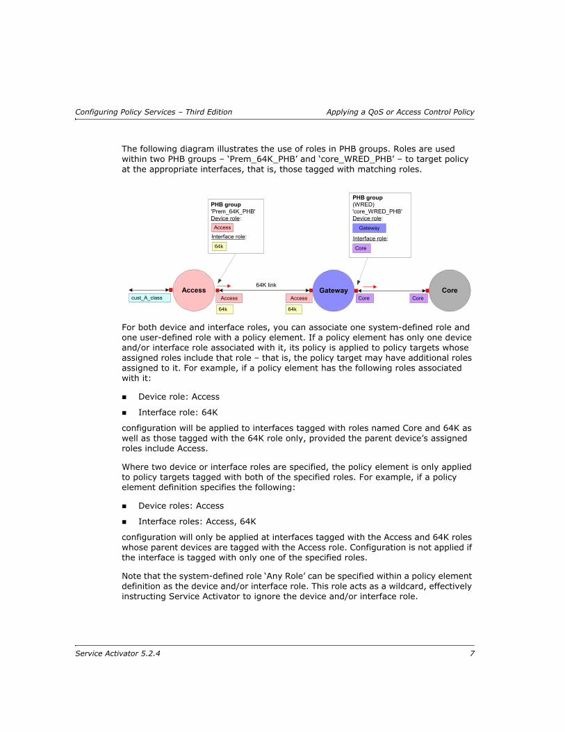
The following diagram illustrates the use of roles in PHB groups. Roles are used within two PHB groups – ‘Prem_64K_PHB’ and ‘core_WRED_PHB’ – to target policy at the appropriate interfaces, that is, those tagged with matching roles.
For both device and interface roles, you can associate one system-defined role and one user-defined role with a policy element. If a policy element has only one device and/or interface role associated with it, its policy is applied to policy targets whose assigned roles include that role – that is, the policy target may have additional roles assigned to it. For example, if a policy element has the following roles associated with it:
Device role: Access
Interface role: 64K
configuration will be applied to interfaces tagged with roles named Core and 64K as well as those tagged with the 64K role only, provided the parent device’s assigned roles include Access.
Where two device or interface roles are specified, the policy element is only applied to policy targets tagged with both of the specified roles. For example, if a policy element definition specifies the following:
Device roles: Access
Interface roles: Access, 64K
configuration will only be applied at interfaces tagged with the Access and 64K roles whose parent devices are tagged with the Access role. Configuration is not applied if the interface is tagged with only one of the specified roles.
Note that the system-defined role ‘Any Role’ can be specified within a policy element definition as the device and/or interface role. This role acts as a wildcard, effectively instructing Service Activator to ignore the device and/or interface role.
Accesscust_A_class
64K link
CoreCoreAccess
64k
PHB group(WRED)'core_WRED_PHB'Device role:
Core
Gateway
Interface role:
CoreAccess
64k
Gateway
PHB group'Prem_64K_PHB'Device role:
64k
Access
Interface role:
Service Activator 5.2.4 7

Applying a QoS or Access Control Policy Configuring Policy Services – Third Edition
In the following example, ‘Any Role’ is specified as the device role. Service Activator therefore disregards the device role and applies the policy element wherever the interface roles match those in the policy element definition.
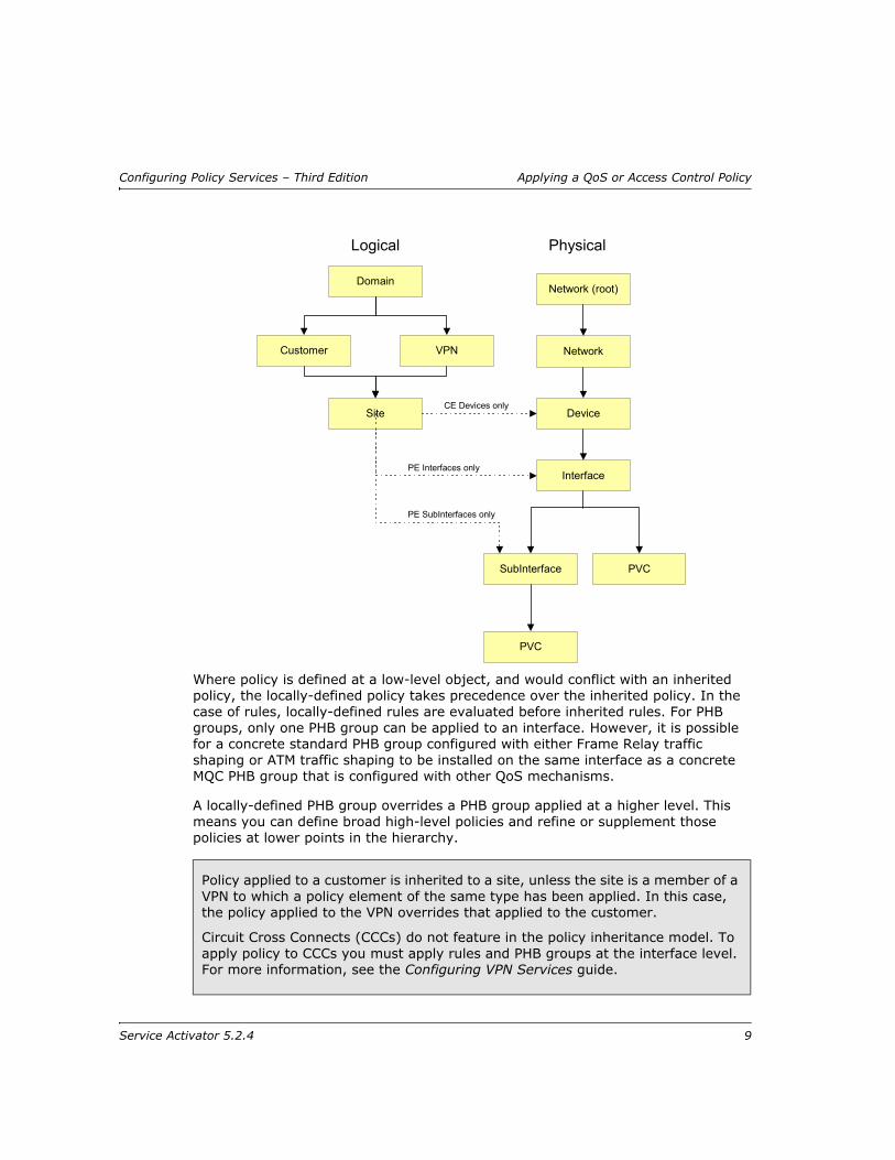
Policy inheritanceService Activator supports a policy inheritance model – QoS or access control policy applied to a policy target is automatically inherited by lower-level objects. For example, a rule that is applied to the network is inherited by the devices that make up that network. Note that devices and interfaces must be tagged with the appropriate role or roles for policy to be inherited.
There are two branches in the inheritance model:
Logical – includes domains, customers and VPNs
Physical – includes networks, devices and interfaces
The branches converge at device level.
Gatewaycust_A_class
64K link
CoreCoreAccess
64K
Access CoreAccess
64K
PHB group(WRED)'core_WRED_PHB'Device role:
Core
Interface role:
Any Role
PHB group'Prem_64K_PHB'Device role:
64K
Access
Any Role
Interface role:
8 Service Activator 5.2.4
Configuring Policy Services – Third Edition Applying a QoS or Access Control Policy
Where policy is defined at a low-level object, and would conflict with an inherited policy, the locally-defined policy takes precedence over the inherited policy. In the case of rules, locally-defined rules are evaluated before inherited rules. For PHB groups, only one PHB group can be applied to an interface. However, it is possible for a concrete standard PHB group configured with either Frame Relay traffic shaping or ATM traffic shaping to be installed on the same interface as a concrete MQC PHB group that is configured with other QoS mechanisms.
A locally-defined PHB group overrides a PHB group applied at a higher level. This means you can define broad high-level policies and refine or supplement those policies at lower points in the hierarchy.
Policy applied to a customer is inherited to a site, unless the site is a member of a VPN to which a policy element of the same type has been applied. In this case, the policy applied to the VPN overrides that applied to the customer.
Circuit Cross Connects (CCCs) do not feature in the policy inheritance model. To apply policy to CCCs you must apply rules and PHB groups at the interface level. For more information, see the Configuring VPN Services guide.
Physical
Network
Interface
Network (root)
Device
SubInterface
PVC
PVC
Site
VPN
CE Devices only
PE Interfaces only
PE SubInterfaces only
Customer
Domain
Logical
Service Activator 5.2.4 9

Applying a QoS or Access Control Policy Configuring Policy Services – Third Edition
When you view the policy that applies to a policy target, Service Activator indicates whether it has been inherited from above or defined at the policy target. For more information, see Checking implemented rules on page 76, Checking implemented PHB groups on page 144.
Before implementing a QoS or access control policyA detailed analysis of the network to be managed and the requirements to be met are essential pre-requisites for implementing a QoS or access control policy.
This section outlines the tasks you need to perform and highlights the points you need to consider when setting up a QoS or access control policy. It assumes that a detailed analysis phase has been performed.
Set up basic dataYou need to make sure that you have set up all necessary class of service (CoS) and rule component data before creating policy rules and PHB groups:
Set up classes of service to associate with PHB groups
A CoS may be defined by a packet marking and/or a classification or classification group. Note that a standard PHB group applies to a CoS characterized by a packet marking, while an MQC PHB group applies to a CoS defined by a classification or classification group. Each PHB group type ignores any ‘irrelevant’ part of a CoS definition.
Set up packet markings (DiffServ codepoints, IP Precedence, MPLS experimental bits and MPLS Topmost experimental bits, Frame Relay DE bit, ATM CLP bit, Alcatel Internal Queue, and Discard-class)
Set up traffic types that identify the categories of traffic that you want to manage
Set up classifications and classification groups that classify existing traffic types by source and/or destination if required
Classifications and classification groups can be associated with policy rules and with the classes of service that you associate with MQC PHB groups.
Set up account groups that identify the source and destination points of the traffic to be managed – optional, as you can also identify source and destination points by IP address within a classification
Set up date and time templates if relevant
For more information, see Setting Up Basic Policy Data on page 25.
10 Service Activator 5.2.4

Configuring Policy Services – Third Edition Applying a QoS or Access Control Policy
Check capabilitiesBefore setting up policy rules and PHB groups, you need to know the capabilities of the interfaces to which you intend to apply policy. Check the Capabilities property page on the properties dialog box of relevant interfaces if necessary. See the Network Discovery and Basic Setup guide for information on retrieving capabilities.
Set up and assign policy rolesPolicy roles can be associated with network components and with rules, PHB groups, and driver scripts. By applying a role to a policy target you effectively specify which policy will be applied at that point. Before setting up rules and PHB groups, you should decide whether to use system and/or user-defined roles and decide which roles to apply to each policy target. You can define role assignment rules to assign roles to policy targets.
For more information, see the Network Discovery and Basic Setup guide.
Assign traffic to appropriate classes of serviceA class of service defines a class of traffic based on packet characteristics allowing traffic on the network to be identified. A CoS can be defined by one or more packet markings (coarse-grained) or by additional parameters such as source and/or destination IP address and traffic type (fine-grained). These additional parameters are defined by a classification or classification group.
A PHB group applies QoS mechanisms to classes of service that are associated with the PHB group. Therefore, before creating PHB groups you need to create suitable classes of service. Note the following:
A standard PHB group applies to a CoS characterized by a packet marking
An MQC PHB group applies to a CoS defined by a classification or classification group
If you associate a CoS that is associated with both a packet marking and a classification or classification group with a standard or MQC PHB group, each PHB group type ignores any ‘irrelevant’ part of a CoS definition. For more information, see Classes of Service on page 35.
Policy rules operate on traffic types, classifications or classification groups. If required, a policy rule can be associated with a class of service (CoS) by creating a policy rule that specifies either the same packet marking associated with the CoS or a classification or classification group that specifies a traffic type that has the same packet marking associated with the CoS. A CoS can have several packet markings and policy rules associated with it.
For more information, see Setting up traffic types on page 40 and Setting up a classification on page 46.
Service Activator 5.2.4 11
Applying a QoS or Access Control Policy Configuring Policy Services – Third Edition
Consider where to apply policy elementsPolicy rules, PHB groups and driver scripts can be created at various levels in Service Activator and are automatically inherited so that they are applied to interfaces tagged with the appropriate role. For example, a rule created at domain level will potentially apply throughout the domain, while one created at device level will apply to that device’s interfaces only.
Organizing QoS objects into user-defined foldersA number of QoS objects can be organized in the Service Activator GUI into folders and sub-folders:
PHBs and MQC PHBs
classifications and classification groups
classes of service (CoS)
roles
For example, PHBs and MQC PHBs are located under the PHB Groups folder in the Policy tab. To create a folder, right-click on the appropriate parent object under the PHB Groups folder, or the PHB Groups folder itself, and select Add Folder from the pop-up menu. To add a PHB or MQC PHB to an interface, simply drag and drop it.
User-defined folders for the other QoS objects are similarly created under their top-level system-defined folder in the Policy tab.
User-defined folders can contain sub-folders. Drag and drop operations can be used to move folders, or their contents. You can also define folder permissions to restrict access to a subset of users for these folders.
For more information on managing user-defined folders, refer to the Service Activator Network Discovery and Basic Setup Guide.
Classification Aggregation Control
Functional Description
Complex object hierarchies can be elaborated to define traffic flows. Different actions will be applied to these elaborations. These classification hierarchies are composed of classifications and classification groups.
The classifications are processed either by the CDD or the NP Cisco cartridgeand are eventually translated into an hierarchy of class-map and ACL when targeting Cisco devices.
12 Service Activator 5.2.4

Configuring Policy Services – Third Edition Applying a QoS or Access Control Policy
The inner logic of aggregation and merging is based on the type of matching (match-all versus match-any), the type of classification (ex.: purely DSCP versus ports and IP addresses, etc), number of child classifications, etc. The fact that the end user is not familiar with this complex logic currently makes predictability and ease of use an issue. In addition, certain configuration patterns, although logically correct, may not be optimal. Or worse, these could prove to be practically unusable in some complex cases without giving users enough control to correct the situation..
Another aspect that can be problematic is the control over choices, like creating a match entry in a class-map versus creating an ACL entry in an access group. This also results from an internal logic based on some unexposed criteria and design choices. This is especially apparent when dealing with DSCP-only classifications.
The basic idea behind adding this functionality is to give the user more direct control over aggregation. Less inner logic intervenes in the process and users can more accurately design the resulting class-map and ACL hierarchy they are looking for. Simply put, when a user selects "aggregate", it will happen regardless of hidden criteria. Additionally, current behavior (parity with CDD processing) is a requirement for CDD to NP migration, making it also necessary to make this approach an alternative.
Therefore, to enable this alternate classifications processing, a check-box is added in the IPSA GUI at the device level.
Service Activator 5.2.4 13

Applying a QoS or Access Control Policy Configuring Policy Services – Third Edition
This new behavior is implemented by the Networkprocessor's Cisco cartridge and simply ignored by other components. Using a new device attribute to turn on this feature instead of using an option in a property file will ease the task of future data migration during upgrades. It will also allow control at a device by device level (versus a globally enabled option per NP instance that would otherwise impose the use of multiple NP instances). This new attribute on the device object is an optional attribute that defaults to the pre-existing behavior (parity with CDD processing).
Previously, naming of Class-map and access-group when aggregation was enabled was using auto-generated names regardless of the type of naming chosen by the user. The new approach uses the names or numbers selected by users for the AclId on the MQC tab of classification or classification groups following rules described in the analysis section (section 3).
14 Service Activator 5.2.4
Configuring Policy Services – Third Edition Applying a QoS or Access Control Policy
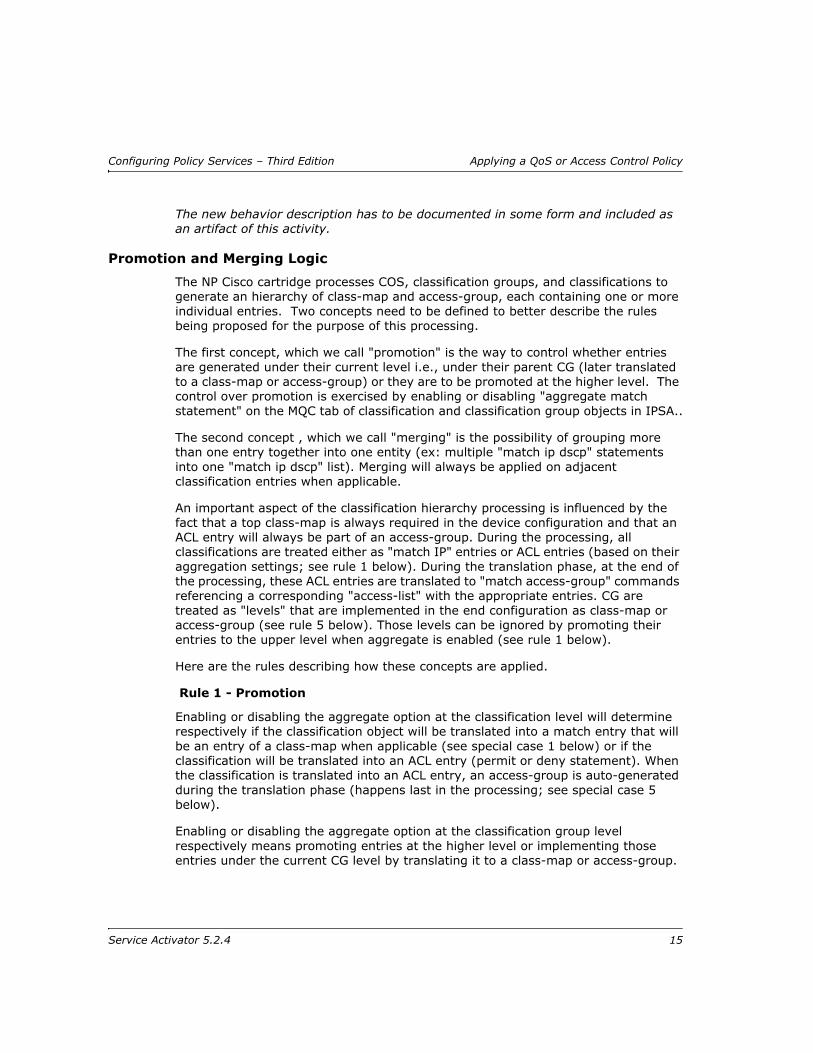
The new behavior description has to be documented in some form and included as an artifact of this activity.
Promotion and Merging Logic
The NP Cisco cartridge processes COS, classification groups, and classifications to generate an hierarchy of class-map and access-group, each containing one or more individual entries. Two concepts need to be defined to better describe the rules being proposed for the purpose of this processing.
The first concept, which we call "promotion" is the way to control whether entries are generated under their current level i.e., under their parent CG (later translated to a class-map or access-group) or they are to be promoted at the higher level. The control over promotion is exercised by enabling or disabling "aggregate match statement" on the MQC tab of classification and classification group objects in IPSA..
The second concept , which we call "merging" is the possibility of grouping more than one entry together into one entity (ex: multiple "match ip dscp" statements into one "match ip dscp" list). Merging will always be applied on adjacent classification entries when applicable.
An important aspect of the classification hierarchy processing is influenced by the fact that a top class-map is always required in the device configuration and that an ACL entry will always be part of an access-group. During the processing, all classifications are treated either as "match IP" entries or ACL entries (based on their aggregation settings; see rule 1 below). During the translation phase, at the end of the processing, these ACL entries are translated to "match access-group" commands referencing a corresponding "access-list" with the appropriate entries. CG are treated as "levels" that are implemented in the end configuration as class-map or access-group (see rule 5 below). Those levels can be ignored by promoting their entries to the upper level when aggregate is enabled (see rule 1 below).
Here are the rules describing how these concepts are applied.
Rule 1 - Promotion
Enabling or disabling the aggregate option at the classification level will determine respectively if the classification object will be translated into a match entry that will be an entry of a class-map when applicable (see special case 1 below) or if the classification will be translated into an ACL entry (permit or deny statement). When the classification is translated into an ACL entry, an access-group is auto-generated during the translation phase (happens last in the processing; see special case 5 below).
Enabling or disabling the aggregate option at the classification group level respectively means promoting entries at the higher level or implementing those entries under the current CG level by translating it to a class-map or access-group.
Service Activator 5.2.4 15
Applying a QoS or Access Control Policy Configuring Policy Services – Third Edition
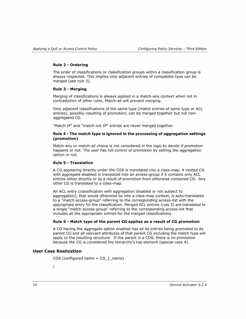
Rule 2 - Ordering
The order of classifications or classification groups within a classification group is always respected. This implies only adjacent entries of compatible type can be merged (see rule 3).
Rule 3 - Merging
Merging of classifications is always applied in a match-any context when not in contradiction of other rules. Match-all will prevent merging.
Only adjacent classifications of the same type (match entries of same type or ACL entries), possibly resulting of promotion, can be merged together but not non-aggregated CG.
"Match IP" and "match not IP" entries are never merged together.
Rule 4 - The match type is ignored in the processing of aggregation settings (promotion)
Match-any or match-all choice is not considered in the logic to decide if promotion happens or not. The user has full control of promotion by setting the aggregation option or not.
Rule 5 - Translation
A CG appearing directly under the COS is translated into a class-map. A nested CG with aggregate disabled is translated into an access-group if it contains only ACL entries either directly or as a result of promotion from otherwise contained CG. Any other CG is translated to a class-map.
An ACL entry (classification with aggregation disabled or not subject to aggregation), that would otherwise be into a class-map context, is auto-translated to a "match access-group" referring to the corresponding access-list with the appropriate entry for the classification. Merged ACL entries (rule 3) are translated to a single "match access-group" referring to the corresponding access-list that includes all the appropriate entries for the merged classifications.
Rule 6 - Match type of the parent CG applies as a result of CG promotion
A CG having the aggregate option enabled has all its entries being promoted to its parent CG and all relevant attributes of that parent CG including the match type will apply to the resulting structure. If the parent is a COS, there is no promotion because the CG is considered the hierarchy's top element (special case 4).
User Case Realization
COS (configured name = CG_1_name)
|
16 Service Activator 5.2.4

Configuring Policy Services – Third Edition Applying a QoS or Access Control Policy
|----- CG_1
|
|
|------- Cl_1 (DSCP 12)
|
|------- Cl_2 (IP source x)
|
|------- Cl_3 (DSCP 22)
|
|------- Cl_4 (DSCP 32)
|
|------- Cl_5 (IP destination y)
1) Aggregation everywhere; Match-any Everywhere
Class-map CG_1_name
Match DSCP 12
Match access-group Cl_2
Match DSCP 22 32 (does not include Cl_1 because of rule 2 - order)
Match access-group Cl_5
Access-group Cl_2
Permit ip source x
Access-group Cl_5
Permit ip destination y
2) Aggregation everywhere except on dscp classifications (Cl_1, Cl_3, Cl_4); Match-any Everywhere
Class-map CG_1_name
Match access-group Cl_1
Access-group Cl_1
Service Activator 5.2.4 17
Applying a QoS or Access Control Policy Configuring Policy Services – Third Edition
Permit dscp 12
Permit ip source x
Permit dscp 22
Permit dscp 32
Permit ip destination y
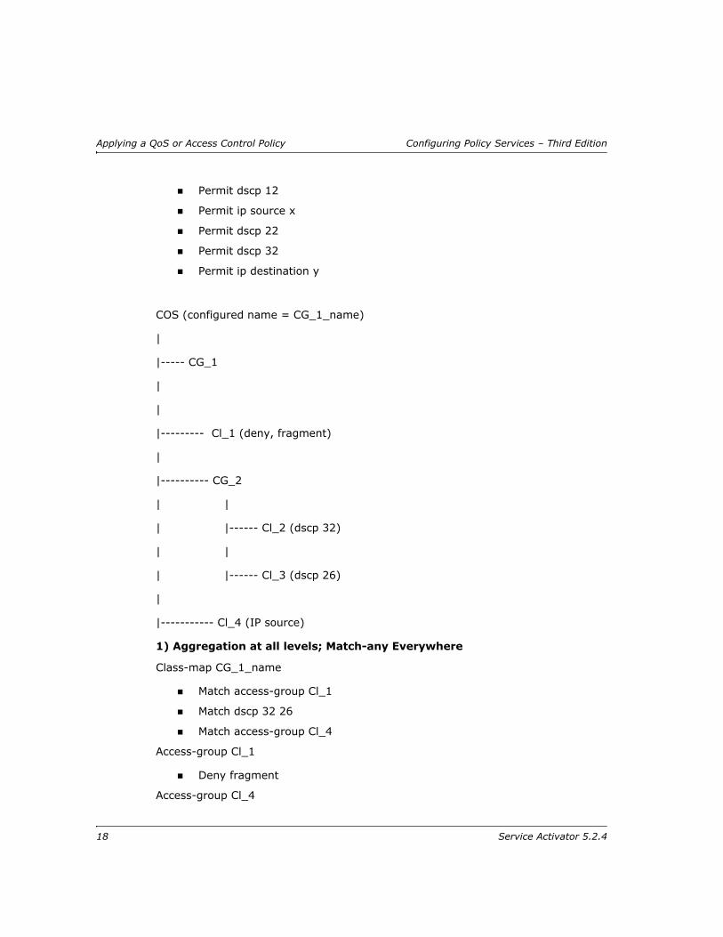
COS (configured name = CG_1_name)
|
|----- CG_1
|
|
|--------- Cl_1 (deny, fragment)
|
|---------- CG_2
| |
| |------ Cl_2 (dscp 32)
| |
| |------ Cl_3 (dscp 26)
|
|----------- Cl_4 (IP source)
1) Aggregation at all levels; Match-any Everywhere
Class-map CG_1_name
Match access-group Cl_1
Match dscp 32 26
Match access-group Cl_4
Access-group Cl_1
Deny fragment
Access-group Cl_4
18 Service Activator 5.2.4
Configuring Policy Services – Third Edition Applying a QoS or Access Control Policy
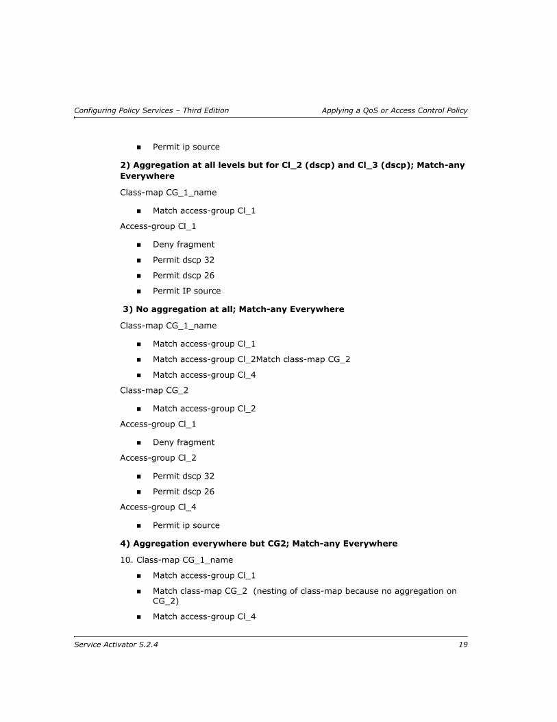
Permit ip source
2) Aggregation at all levels but for Cl_2 (dscp) and Cl_3 (dscp); Match-any Everywhere
Class-map CG_1_name
Match access-group Cl_1
Access-group Cl_1
Deny fragment
Permit dscp 32
Permit dscp 26
Permit IP source
3) No aggregation at all; Match-any Everywhere
Class-map CG_1_name
Match access-group Cl_1
Match access-group Cl_2Match class-map CG_2
Match access-group Cl_4
Class-map CG_2
Match access-group Cl_2
Access-group Cl_1
Deny fragment
Access-group Cl_2
Permit dscp 32
Permit dscp 26
Access-group Cl_4
Permit ip source
4) Aggregation everywhere but CG2; Match-any Everywhere
10. Class-map CG_1_name
Match access-group Cl_1
Match class-map CG_2 (nesting of class-map because no aggregation on CG_2)
Match access-group Cl_4
Service Activator 5.2.4 19
Applying a QoS or Access Control Policy Configuring Policy Services – Third Edition
Class-map CG_2
Match dscp 32 26
Access-group Cl_1
Deny fragment
Access-group Cl_4
Permit ip source
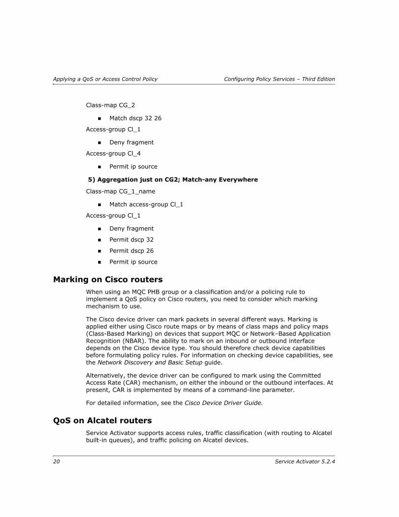
5) Aggregation just on CG2; Match-any Everywhere
Class-map CG_1_name
Match access-group Cl_1
Access-group Cl_1
Deny fragment
Permit dscp 32
Permit dscp 26
Permit ip source
Marking on Cisco routers When using an MQC PHB group or a classification and/or a policing rule to implement a QoS policy on Cisco routers, you need to consider which marking mechanism to use.
The Cisco device driver can mark packets in several different ways. Marking is applied either using Cisco route maps or by means of class maps and policy maps (Class-Based Marking) on devices that support MQC or Network–Based Application Recognition (NBAR). The ability to mark on an inbound or outbound interface depends on the Cisco device type. You should therefore check device capabilities before formulating policy rules. For information on checking device capabilities, see the Network Discovery and Basic Setup guide.
Alternatively, the device driver can be configured to mark using the Committed Access Rate (CAR) mechanism, on either the inbound or the outbound interfaces. At present, CAR is implemented by means of a command-line parameter.
For detailed information, see the Cisco Device Driver Guide.
QoS on Alcatel routersService Activator supports access rules, traffic classification (with routing to Alcatel built-in queues), and traffic policing on Alcatel devices.
20 Service Activator 5.2.4

Configuring Policy Services – Third Edition Applying a QoS or Access Control Policy
QoS on Juniper M-series routersService Activator supports access rules rate limiting and WRR on Juniper M-series devices. For detailed information, see the Juniper Device Driver Technical Note.
Implementing policyAs you create the rules and PHB groups that define the policy to be applied to the network, they are queued in the current transaction. Depending on your user access level, you may be able to commit the transaction immediately, or save it in a pending state for checking and committing by a supervisor. The policy defined by a rule or PHB group is not implemented until the transaction it forms part of is committed. For information on transactions, see the Network Discovery and Basic Setup guide.
When a transaction is committed, the policy associated with it is validated and details of any concrete configuration elements or faults created by the transaction are displayed in a dialog box. At this point, you can choose to cancel the commit and correct any errors or faults. If you choose to continue with the commit, the policy is sent to the proxy agents. All changes that have occurred since the last propagate are sent to the appropriate proxy agents.
If configuration is to be implemented immediately – that is, if a rule is not dependent on a particular time period – the proxy agent instructs the device drivers to update the configuration of the relevant routers.
The status bar’s System Configuration field indicates the progress of the policy update. It indicates the proportion of concrete objects that have been configured on devices – that is, rules, PHB groups, VPNs, TLSs, CCCs, Layer 2 Martini VPNs and driver scripts. The proportion is shown as a percentage of the number of concrete objects within Service Activator:
A value less than 100% indicates that concrete policy objects have been propagated to a proxy agent but are not installed on the device.
A value of 100% indicates that all concrete objects have been propagated to devices. However, it does not necessarily mean that all devices have been configured successfully – check the current faults pane for errors.
Where policy rules are not to be implemented until a particular time period, the new configuration is not sent to the device driver until it is required.
If necessary, you may be able to undo the effect of a committed transaction and restore network devices to their previous configuration. For information, see the Network Discovery and Basic Setup guide.
Service Activator 5.2.4 21

Applying a QoS or Access Control Policy Configuring Policy Services – Third Edition
Abstract and concrete policy elementsCommitting a transaction that propagates a rule, PHB group or driver script to the network may result in the creation of concrete policy elements. A concrete policy element is an implementation of a defined rule, PHB group or driver script that applies to a specific point in the network, that is, at a particular interface, sub-interface or VC endpoint. Each abstract or parent policy element set up can result in a number of concrete policy elements.
The following diagram illustrates the concept with a classification rule.
You can list implemented rules, PHB groups, VPNs or driver scripts for a policy target in the details pane. Service Activator indicates whether the policy element is abstract or concrete:
White background – an abstract policy element that has been set up on the selected object
Yellow background, indented – a concrete policy element that exists at the current or a lower level in the hierarchy
Gray background – an abstract policy element that has been inherited from a higher level object
Gray background, indented – a concrete policy element for an inherited policy element
The following screenshots illustrate the background color used for abstract, inherited and concrete PHB groups. The PHB group ‘Prem_64k_PHB’ is applied to a network object named ‘Global’ and inherited by an interface at a lower level in the hierarchy.
The PHB group listing for the Global object looks as follows:
Classification Rule
Parent rule -created within the
system
A set of concrete rules- implemented on
interfaces
Concrete rule Concrete rule Concrete rule Concrete rule
22 Service Activator 5.2.4

Configuring Policy Services – Third Edition Applying a QoS or Access Control Policy
The PHB group listing at the interface that inherits the PHB group looks like this:
For information on viewing implemented policy rules, see page 77. For information on viewing summary information about abstract and concrete rules, see page 76. For information about searching for concrete rules by type and status, see page 76.
White background indicates that Prem_64k_PHB was applied at the Global network object
Yellow background indicates that a concrete object exists at the listed interface
Gray background indicates that Prem_64k_PHB is inherited from the Global network object
Gray indented background indicates that a concrete object exists for the inherited PHB group
Service Activator 5.2.4 23

Applying a QoS or Access Control Policy Configuring Policy Services – Third Edition
24 Service Activator 5.2.4

Configuring Policy Services – Third Edition Setting Up Basic Policy Data
Chapter 2
Setting Up Basic Policy Data
This section describes the basic data you need to define before setting up a QoS or security policy. This includes the following:
Importing policy files – how to load optional files that provide values for standard IP Precedence codepoints and MPLS experimental bits, and sample policy rules, role assignment rules, and PHB groups
Class of service data – needed if you are setting up a QoS policy
Rule components – IP protocols, traffic types, classifications, and date and time templates, used when setting up rules and classes of service
Accounts – optionally used to identify the users of services
Service Activator 5.2.4 25

Setting Up Basic Policy Data Configuring Policy Services – Third Edition
Importing policy filesYou can load the following files that provide standard values for IP Precedence codepoints and MPLS experimental bits:
The default.policy file – creates some basic policy data, including basic Gold, Silver and Bronze classes of service and their associated codepoints and traffic types. If you do not load this default data, you will have to create all the basic component data yourself. Do not import this policy file into a domain which has already imported the old default.policy file or default.dscp.policy file.
The default.dscp.policy file – creates DSCP values. This file is a variant of the default.policy file and is compatible with IPSA releases prior to 5.1.3. It may be more appropriate to be used when not using the network processor. Packet marking policies use DSCP values, instead of IP Precedence values. Do not import this policy file into a domain which has already imported the new default.policy file.
The advanced.policy file – creates additional packet markings and classes of service, as well as classifications, classification groups and traffic types. This data will be useful if your routers support the full range of DiffServ codepoints, IP Precedence value and/or MPLS experimental bits.
You can load the following files that provide sample policy rules, role assignment rules, and PHB groups. You can use these as a basis for creating your own rules and PHB groups:
Rule_and_PHB.policy file – creates some example policy rules, PHB groups and role assignment rules.
Role_Assignment_Rules.policy file – defines a set of role assignment rules that allocate system-defined roles to devices and interfaces.
You can also load the following files:
alcatel.policy file – for Alcatel 7670 devices; defines relevant MPLS packet marking objects and traffic types.
juniper.policy file – for Juniper M-series devices; defines relevant MPLS packet markings, sets up classes of service based on these markings and creates an example PHB group with WRR configured. For more information, see the Juniper Device Driver Technical Note.
SharedPolicyData.policy file – loaded automatically at system startup. It defines a set of commonly-used IP protocols which are available in any domain you create. You only need to load this file if the IP protocols are deleted or edited incorrectly.
All of the above files are domain-specific – that is, they must be loaded into each domain in which you wish to use their data.
26 Service Activator 5.2.4

Configuring Policy Services – Third Edition Setting Up Basic Policy Data
To load a policy configuration file
1. On the Domain dialog box, select the Setup tab.
2. Click Browse to view the available configuration files in the SamplePolicy folder.
3. Select the file to load and click Open. A brief explanation of the file appears in the File Information box.
4. Click Load to load the selected file and create the data. Note that these files must be loaded in the following order:
1. default.policy
2. advanced.policy
3. Rule_and_PHB.policy
You must specify the device and interface roles to which these example standard PHB groups apply before using them. For information on using roles in policy elements, see Using roles in policy elements on page 6.
Class of service dataClasses of service define classes of traffic based on packet characteristics allowing traffic on the network to be identified. Specific QoS mechanisms, such as a guaranteed bandwidth or a particular queuing priority, can be applied to specific classes of traffic.
Traffic is allocated to a Class of Service (CoS) according to how the CoS is defined. A CoS can be defined by packet marking, source/destination IP/MAC address, account or traffic type. Subsequent routers can then read the header and treat packets in accordance with the CoS to which they have been allocated. For example, rate limiting (traffic shaping) techniques and queuing mechanisms can be applied. Or, if traffic belonging to a particular CoS exceeds its agreed bandwidth, it can be dropped or re-marked if necessary.
Do not load Rule_and_PHB.policy if you have already created standard PHB groups.
For a more detailed discussion of Differentiated Service techniques, see the Product Overview.
Service Activator 5.2.4 27

Setting Up Basic Policy Data Configuring Policy Services – Third Edition
The CoS data used by Service Activator is fundamental to establishing a policy-based QoS system. It consists of the following:
Packet Markings – these define the bit settings with which identify which traffic class IP or MPLS packets belong to. You can use Packet Markings to determine which class a packet belongs to, or to change its class by re-marking.
The types of packet marking available are:
DiffServ codepoints – IP DiffServ codepoint bits in the DiffServ field of the IP packet header
IP Precedence – IP Precedence bits in the IP Precedence field of the IP packet header
MPLS experimental bits – CoS/experimental bits section of the MPLS header
MPLS Topmost experimental bits – CoS/experimental bits section of the topmost MPLS header
Frame Relay Discard Eligible bit – DE bit of the address field of the Frame Relay frame header
ATM Cell Loss Priority bit – CLP bit in the ATM cell header
Alcatel Internal Queue – Alcatels 8 queue / 3 queue / 1 queue scheme
Discard-class – marks packets on the RX card so that WRED can be applied on the TX card.
Trust Type – specifies which CoS type is to be trusted. The options are: untrusted, trust-cos, trust-ipprec, trust-dscp.
Classes of Service – define classification categories for identifying traffic on the network. Classes of service can be defined by packet marking (coarse grained), or by more detailed classifications such as source and/or destination IP address and traffic type (fine grained).
802.1p user priority – enable the use of classes of service in Ethernet networks. (Not used by any supported devices at present.)
Packet markingsPacket markings can be used to identify to which class of service packets belong. You can use any of the following packet markings:
DiffServ codepoint – up to 64 DiffServ codepoints can be set up, each one corresponding to a different setting in the header of an IP packet
IP Precedence – Up to seven IP Precedence values can be defined, each one corresponding with a different setting in the header of an IP packet
28 Service Activator 5.2.4

Configuring Policy Services – Third Edition Setting Up Basic Policy Data
MPLS experimental bits – up to eight MPLS experimental bit values can be defined, each one corresponding to a CoS experimental bit value in the MPLS label
MPLS Topmost experimental bits – up to eight MPLS topmost experimental bit values can be defined, each one corresponding to a CoS experimental bit value in the topmost MPLS label
Discard-class – 0 to 7 values can be defined, each one corresponding to a different setting indicating the type of traffic to be dropped when there is a congestion in the network.
Frame Relay Discard Eligible bit – 0 or 1 in the Address field of the Frame Relay frame header
ATM Cell Loss Priority bit – 0 or 1 in the ATM cell header
You can load the following policy configuration files that provide standard IP DiffServ codepoint values for IP Precedence codepoints and values for MPLS experimental bits:
The default.policy file
The advanced.policy file
The packet markings defined by these files are described in the following sections.
You can make changes to the packet markings created by these files if you wish:
You can rename existing codepoints, though we recommend that you do not change standard names
You can create new codepoints, though you should ensure that they can be recognized by devices
DiffServ codepoints
Each DiffServ codepoint corresponds to a setting in the IP Precedence/DiffServ codepoint section of the header of an IPv4 or IPv6 packet. The DiffServ standard defines a 6-bit field, allowing up to 64 codepoints. As a result, up to 64 classes of service may be defined.
Packet markings that specify settings for the Frame Relay Discard Eligible bit and/or ATM Cell Loss Priority bit can only be used by classes of service associated with MQC PHB groups.
Support is also provided for 802.1 priority bits, but these bits are not currently supported by any of Service Activator’s supported device types.
Service Activator 5.2.4 29

Setting Up Basic Policy Data Configuring Policy Services – Third Edition
Packets can be re-marked at any point in the network using classification rules or using MQC PHB groups. For information on defining classification rules, see Classification rules on page 64. For more information on defining MQC PHB groups, see Defining MQC PHB Groups on page 111.
The codepoints that are defined in Service Activator are listed in the Packet Markings folder on the Policy tab. Service Activator includes a set of policy configuration files that you can load into Service Activator to set up basic standard codepoints, see Importing policy files on page 26. You can also define codepoints in the user interface.
IP Precedence
Each IP Precedence value corresponds to a setting in the IP Precedence section of the header of an IPv4 or IPv6 packet. There are eight classes of services in IP Precedence. The classification range is 0-7 where 0 (zero) is the lowest and 7 is the highest priority. However, at present some routers have not yet fully implemented IP Precedence bits.
MPLS experimental bits
For MPLS traffic, a label is attached to each IP packet at the ingress router to the Label Switched Path (LSP). This label is used by routers when forwarding packets along the path, and the IP packet header is not examined at any point along the LSP. The three IP Precedence bits are copied from the IP header into the three bits within the MPLS label known as the MPLS experimental bits or CoS experimental bits.
The application that generates the IPv4 or IPv6 packet controls the original IP Precedence value. However, some devices are able to reset this value, which can be useful if a precedence is set for a packet at the edge of the network and a service provider wants to override this value while the packet transits the core.
Service Activator is able to set the MPLS experimental bits where this is supported by devices.
Packets can be remarked at any point in the network using classification rules or MQC PHB groups. For information on defining classification rules, see Classification rules on page 64. For more information on defining MQC PHB groups, see Defining MQC PHB Groups on page 111.
Before setting up a QoS policy, you need to know which codepoints are supported on the devices in your network – for example, whether they can recognize and mark with the full range of DiffServ codepoints or just the IP Precedence bits. To check the codepoints supported on a particular interface, see the appropriate Capabilities property page. For more information on viewing an interface’s capabilities see the Network Discovery and Basic Setup guide.
30 Service Activator 5.2.4
Configuring Policy Services – Third Edition Setting Up Basic Policy Data
Note: Classes of service using MPLS Experimental bits are supported by Service Activator for inbound traffic only. When you select both an inbound and out-bound MQC PHB phb using MPLS Experimental, the error states that there is a problem with the default class of service.
MPLS Topmost experimental bits
These are the same bits as the MPLS experimental bits, but set only on the topmost MPLS label on a packet. MPLS labels are added to IP packets on entry to an MPLS network. Typically, the three IP Precedence bits are copied from the IP header into these bits. Some devices are able to reset this value, which can enable the service provider to override a packet’s precedence while it transits the core. Some devices also support setting and evaluating the MPLS experimental bits only on the Topmost MPLS label.
These bits are also referred to as CoS experimental bits.
Packets can be remarked at any point in the network using classification rules or MQC PHB groups. The MPLS Topmost packet marking is used to mark the MPLS Experimental bits in only the topmost MPLS label of a packet. This Packet Marking is applicable only in MQC PHBs and only to perform policing and marking actions. Other actions will trigger the device to return errors which are then displayed in the Faults pane.
For information on defining classification rules, see Classification rules on page 64. For more information on defining MQC PHB groups, see Defining MQC PHB Groups on page 111.
Frame Relay Discard Eligible bit
The Frame Relay DE bit is part of the Frame address field in the Frame Relay frame header. This bit is normally set to indicate that the frame has a lower importance than other frames. When congestion occurs, frames with the DE bit set will be dropped before frames whose DE bits are not set.
ATM Cell Loss Priority bit
The ATM CLP bit is part of the ATM Cell header. This bit is normally set to indicate that the cell has a lower importance than other cells. When congestion occurs, cells with the CLP bit set will be dropped before frames whose CLP bits are not set.
Discard-class
You can use this command to specify the type of traffic that will be dropped when there is congestion. This command marks a packet on the RX card so that WRED can be applied on the TX card.
Service Activator 5.2.4 31
Setting Up Basic Policy Data Configuring Policy Services – Third Edition
Trust Type
This configures the trust state, which selects the value that QoS uses as the source of the internal DSCP value. For example, if Trust type is set to trust-ipprec, the ToS bits in the incoming packets contain an IP precedence value and derives the internal DSCP value from the IP precedence bits.
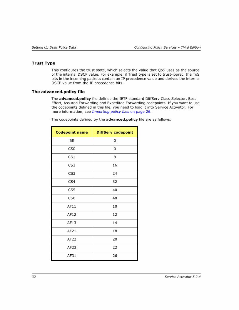
The advanced.policy file
The advanced.policy file defines the IETF standard DiffServ Class Selector, Best Effort, Assured Forwarding and Expedited Forwarding codepoints. If you want to use the codepoints defined in this file, you need to load it into Service Activator. For more information, see Importing policy files on page 26.
The codepoints defined by the advanced.policy file are as follows:
Codepoint name DiffServ codepoint
BE 0
CS0 0
CS1 8
CS2 16
CS3 24
CS4 32
CS5 40
CS6 48
AF11 10
AF12 12
AF13 14
AF21 18
AF22 20
AF23 22
AF31 26
32 Service Activator 5.2.4

Configuring Policy Services – Third Edition Setting Up Basic Policy Data
The MPLS experimental bits defined by the advanced.policy file are as follows:
Creating a new packet marking
You create packet markings on the Policy tab.
To create a new packet marking
1. On the Policy tab, select the Packet Markings folder.
2. Select Add Packet Marking from the pop-up menu.
The Packet Marking dialog box opens.
AF32 28
AF33 30
AF41 34
AF42 36
AF43 38
EF 46
NameMPLS experimental
bit value
MPLS Exp 0 0
MPLS Exp 1 1
MPLS Exp 2 2
MPLS Exp 3 3
MPLS Exp 4 4
MPLS Exp 5 5
MPLS Exp 6 6
MPLS Exp 7 7
Codepoint name DiffServ codepoint
Service Activator 5.2.4 33

Setting Up Basic Policy Data Configuring Policy Services – Third Edition
3. Enter the following details:
— Name: an identifying name for the marking object
— Marking: do one of the following:
— Select DiffServ Codepoint and define the appropriate codepoint value in the range 0-63
— Select IP Precedence and define the appropriate value in the range 0-7
— Select MPLS - Experimental and define the appropriate bit value in the range 0-7
— Select MPLS - Topmost Experimental and define the appropriate bit value in the range 0-7
— Select Frame Relay Discard Eligible and specify either Enabled or Disabled
— Select ATM Cell Loss Priority and specify either Enabled or Disabled
— Select Alcatel Internal Queue, one of the 8CoS, 3Cos, or 1. select an Alcatel Drop Precedence value.
— Select Discard-class and assign a value in the range 0-7.
34 Service Activator 5.2.4

Configuring Policy Services – Third Edition Setting Up Basic Policy Data
— Select Trust Type and choose a value from the options trust-cos, trust-ipprec, and trust-dscp.
4. Click OK to close the dialog box.
Migrating from IP Precedence to DSCPMigrating from an IP Precedence-based configuration to a DSCP-based configuration is accomplished through changes to the Service Activator capabilities files. When this change is made, Service Activator is not able to replace the Precedence entries with the DSCP entries within IP extended access-lists. This is because once the capabilities of the device driver have been changed to support DSCP, the device driver no longer parses or removes existing IP Precedence values. In this case, both IP Precedence and DSCP entries remain in the access-lists.
Once the new DSCP based configuration is verified to be correct, the remaining IP Precedence entries must be manually removed. If they are not manually removed Service Activator will continually attempt to remove the IP Precedence values on every device configuration.
Classes of ServiceA class of service (CoS) categorizes a quality of service level that can be applied to identified network traffic. You associate classes of service with standard PHB groups and MQC PHB groups:
When associated with a standard PHB group, a CoS specifies the queuing mechanism to be applied to a traffic class.
When associated with an MQC PHB group, a CoS allows a complete QoS policy to be applied to a traffic class including mechanisms for queuing, shaping, policing and re-marking.
A PHB group may have one or more classes of service associated with it. You can apply PHB groups to the network or specific devices and in this way specify how traffic in each CoS is treated.
A CoS can be defined in terms of the following:
One or more packet markings (coarse-grained)
A classification or classification group – classifications may be defined, for example, by source and/or destination IP address or account and traffic type (fine-grained)
Note that if you have loaded the default.policy file and/or advanced.policy file, packet markings for some DiffServ codepoints and MPLS experimental bit values will already exist.
Service Activator 5.2.4 35
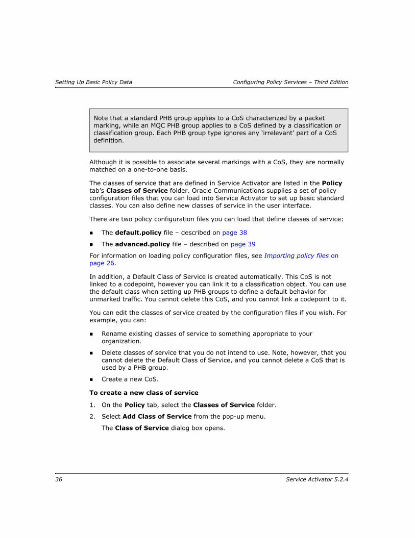
Setting Up Basic Policy Data Configuring Policy Services – Third Edition
Although it is possible to associate several markings with a CoS, they are normally matched on a one-to-one basis.
The classes of service that are defined in Service Activator are listed in the Policy tab’s Classes of Service folder. Oracle Communications supplies a set of policy configuration files that you can load into Service Activator to set up basic standard classes. You can also define new classes of service in the user interface.
There are two policy configuration files you can load that define classes of service:
The default.policy file – described on page 38
The advanced.policy file – described on page 39
For information on loading policy configuration files, see Importing policy files on page 26.
In addition, a Default Class of Service is created automatically. This CoS is not linked to a codepoint, however you can link it to a classification object. You can use the default class when setting up PHB groups to define a default behavior for unmarked traffic. You cannot delete this CoS, and you cannot link a codepoint to it.
You can edit the classes of service created by the configuration files if you wish. For example, you can:
Rename existing classes of service to something appropriate to your organization.
Delete classes of service that you do not intend to use. Note, however, that you cannot delete the Default Class of Service, and you cannot delete a CoS that is used by a PHB group.
Create a new CoS.
To create a new class of service
1. On the Policy tab, select the Classes of Service folder.
2. Select Add Class of Service from the pop-up menu.
The Class of Service dialog box opens.
Note that a standard PHB group applies to a CoS characterized by a packet marking, while an MQC PHB group applies to a CoS defined by a classification or classification group. Each PHB group type ignores any ‘irrelevant’ part of a CoS definition.
36 Service Activator 5.2.4

Configuring Policy Services – Third Edition Setting Up Basic Policy Data
3. Specify an identifying name and a configured name for the CoS and click OK.
To associate a specific packet marking with a CoS
Either:
— Organize the display so that the relevant packet marking and CoS are both visible.
Packet markings and classes of service are listed on the Policy tab.
— Drag the marking object on to the CoS.
Service Activator lists the associated packet marking on the CoS’s Packet Marking property page.
or:
— On the Policy tab, select the relevant CoS and select Properties from the pop-up menu.
The CoS dialog box opens.
— Select the Packet Marking property page and select the checkbox associated with the relevant packet marking.
You can select a number of packet markings to associate with a CoS.
Service Activator 5.2.4 37
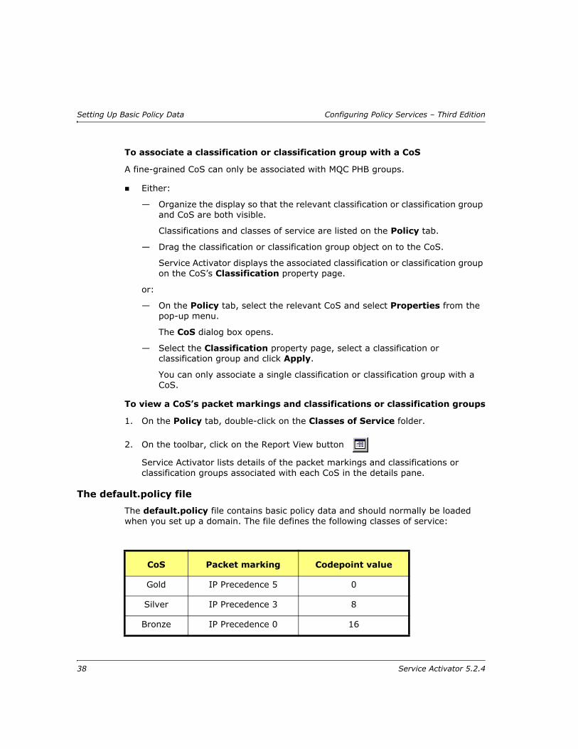
Setting Up Basic Policy Data Configuring Policy Services – Third Edition
To associate a classification or classification group with a CoS
A fine-grained CoS can only be associated with MQC PHB groups.
Either:
— Organize the display so that the relevant classification or classification group and CoS are both visible.
Classifications and classes of service are listed on the Policy tab.
— Drag the classification or classification group object on to the CoS.
Service Activator displays the associated classification or classification group on the CoS’s Classification property page.
or:
— On the Policy tab, select the relevant CoS and select Properties from the pop-up menu.
The CoS dialog box opens.
— Select the Classification property page, select a classification or classification group and click Apply.
You can only associate a single classification or classification group with a CoS.
To view a CoS’s packet markings and classifications or classification groups
1. On the Policy tab, double-click on the Classes of Service folder.
2. On the toolbar, click on the Report View button
Service Activator lists details of the packet markings and classifications or classification groups associated with each CoS in the details pane.
The default.policy file
The default.policy file contains basic policy data and should normally be loaded when you set up a domain. The file defines the following classes of service:
CoS Packet marking Codepoint value
Gold IP Precedence 5 0
Silver IP Precedence 3 8
Bronze IP Precedence 0 16
38 Service Activator 5.2.4

Configuring Policy Services – Third Edition Setting Up Basic Policy Data
The advanced.policy file
The advanced.policy file defines additional classes of service corresponding to the IETF standard DiffServ codepoints. The standard classes of service have the same names as the DiffServ codepoints they are linked to, such as “IP Precedence 1” and “Expedited Forwarding”. For a list of standard DiffServ codepoints, see page 32.
If you want to use the codepoints defined in this file, you need to load it into Service Activator. For more information, see Importing policy files on page 26.
802.1p user priorityAs well as DiffServ codepoints, Service Activator supports 802.1p user priority settings, which enable classes of service to be implemented on Ethernet LANs as well as on an IP network. Three User Priority bits in the Ethernet frame allow eight standard priority levels for Layer 2 traffic, from Best Effort (0) to Network Control (7).
Service Activator includes the standard set of eight user priorities with which Ethernet frames can be marked. You can view them in the 802.1p User Priority folder on the Policy tab. As they are an agreed standard, you are strongly advised not to change them. However, if they are not supported in your network, you can delete them.
Policy componentsPolicy components are the standard definitions and templates that can be used when setting up policy rules and MQC PHB groups. These include:
Traffic types – define the network traffic that can be affected by rules and MQC PHB groups. If you have loaded the default configuration files, a number of traffic types are already included in Service Activator, defining traffic according to port number and CoS (Gold, Silver and Bronze). If you wish, you can define further traffic types that identify specific network traffic that you want to manage.
Classifications and classification groups – define network traffic by source and/or destination IP address or account and traffic type. If you have loaded the default configuration files, a number of classification groups are already included in Service Activator, defining traffic according to traffic type and source and destination IP address. If you wish, you can define further classifications and classification groups. Classifications and classification groups can be used with policy rules and with the classes of service associated with MQC PHB groups.
802.1p user priority settings are not used by any supported devices at present.
Service Activator 5.2.4 39

Setting Up Basic Policy Data Configuring Policy Services – Third Edition
Date and time templates – specify the time periods during which rules are active, if they are only to apply at certain times. The use of date and time templates is optional – it is also possible to specify the effective dates and times manually when you set up the policy rule.
IP protocols – define the transport protocols that can be used when defining a traffic type by port and IP protocol.
Setting up traffic typesYou need to set up traffic types to identify the different categories of network traffic to which you want to apply a specific QoS or security policy using policy rules or MQC PHB groups.
You can set up traffic types based on a number of different methods of classifying traffic:
Port Traffic Type – Source or destination port number and/or IP protocol. This is the most common way of classifying traffic since it is supported on all devices.
Packet Marking – DiffServ codepoint, IP Precedence, MPLS experimental bits, Frame Relay DE bit, ATM CLP bit, Alcatel Internal Queue, or Discard-class.
Note that traffic types that use packet markings specifying settings for the Frame Relay Discard Eligible bit and/or ATM Cell Loss Priority bit can only be used by classifications associated with classes of service associated with MQC PHB groups.
Domain Name – DNS domain name.
Application – name of application protocol within the application, e.g. http.
Sub-application – name of sub-application, e.g. H.323 video.
URL – one or more URLs.
MIME – the MIME type returned by HTTP and, if supported, the minimum and maximum packet length.
The following table summarizes the traffic types that are supported by Service Activator’s device drivers. For more information, see the appropriate device driver guides.
Traffic typeAlcatel
(OS 2.2) CiscoJuniperM-series
JuniperE-series
Port /IP protocol ×
DiffServ codepoint ×
40 Service Activator 5.2.4

Configuring Policy Services – Third Edition Setting Up Basic Policy Data
* ToS bits only
The actual support for particular traffic classification methods is interface-specific, and you should always check the capabilities of an interface.
To view the classification capabilities of a specific interface, display its properties pages. The Capabilities page lists the device capabilities: select Classify under Access, Classification or Policing for details of the traffic types supported. For more information on viewing interface capabilities, see the Network Discovery and Basic Setup guide.
A number of default traffic types are set up when you load the default.policy configuration file. You can view these traffic types in the Policy tab’s Traffic Types folder. This folder contains two subfolders:
The Standard Traffic Types folder includes traffic types that allow you to identify traffic by standard DiffServ codepoints – IP precedence values 0, 3 and 5 corresponding to the Bronze, Silver and Gold classes of service.
The Standard Port Numbers folder includes a number of traffic types identifying the most common TCP and UDP port numbers.
IP Precedence × × ×
MPLS experimental bits × × ×
IP Address ×
Domain × × × ×
Application × × ×
Sub-application × × × ×
URL × × ×
MIME × × ×
Note that on Cisco devices Application, URL and MIME traffic types are only supported on devices that support Network-based Application Recognition (NBAR) and MQC. For more information see the Cisco Device Driver Guide.
Traffic typeAlcatel
(OS 2.2) CiscoJuniperM-series
JuniperE-series
Service Activator 5.2.4 41
Setting Up Basic Policy Data Configuring Policy Services – Third Edition
There is also a default traffic type available, which can be applied to all non-classified traffic. This enables you to apply rules to all traffic that is not defined by another group.
Additional traffic types may be created by loading the advanced.policy configuration file. These traffic types are held in subfolders in the Policy tab’s Traffic Types folder:
The DSCP Values folder includes traffic types that allow you to identify traffic by DiffServ codepoint values
The IP Precedence folder includes traffic types that allow you to identify traffic by IP Precedence values
The IP Protocols folder includes traffic types that allow you to identify traffic by IP protocol
The MPLS EXP Values folder includes traffic types that allow you to identify traffic by MPLS experimental bit value
You can edit the available traffic types in the following ways:
Set up additional traffic types to identify specific network traffic.
Set up a compound traffic type when you need to identify traffic which combines two or more traffic types, for example, packets that are both from a particular port (defined by a port traffic type) and a specific URL (defined by URL traffic type).
You can also set up a traffic type group when you want to organize traffic types into a logical or hierarchical structure.
To set up a port-based traffic type
1. On the Policy tab, select the Traffic Types folder.
Alternatively, to add a traffic type to an existing group, expand the Traffic Types folder and select the appropriate folder.
2. Select Add Port Traffic from the pop-up menu. The Port Traffic Type dialog box is displayed.
3. On the Traffic Type property page, specify the Name and Remarks.
4. On the Port Traffic property page, specify source and destination ports.
5. On the Protocol Options property page, specify the TCP flags and select an ICMP options from Messages menu.
6. Click OK to close the dialog box.
For complete dialog box and property page descriptions, refer to the Online Help.
42 Service Activator 5.2.4

Configuring Policy Services – Third Edition Setting Up Basic Policy Data
To set up other traffic types
1. On the Policy tab, select the Traffic Types folder.
Alternatively, to add a traffic type to an existing group, expand the Traffic Types folder and select the appropriate folder.
2. Select the appropriate Add... Traffic command from the pop-up menu. Choices include:
Add Port Traffic
Add Packet Marking Traffic
Add Domain Name Traffic
Add Application Traffic
Add Sub-application Traffic
Add MIME Traffic
Add URL Traffic
Add Traffic Group
Add Compound Traffic
For example, select Add Packet Marking Traffic to set up a new packet marking-based traffic type.
3. On the Traffic Type property page for the traffic type dialog box which displays, specify Name and Remarks.
4. Select the <Traffic Type> Traffic property page to define further details for the traffic type. The information required depends on the traffic type being defined.
Note: For complete dialog box and property page descriptions, refer to the Online Help.
To define… Do this…
A packet marking-based traffic type:
On the Packet Marking Traffic page of the Packet Marking Traffic dialog box select the checkbox of a packet marking type you require and specify a value.
A domain name-based traffic type:
On the Domain Name Traffic page of the Domain Name Traffic dialog box, in the Domain Name field, specify the DNS domain name.
Service Activator 5.2.4 43
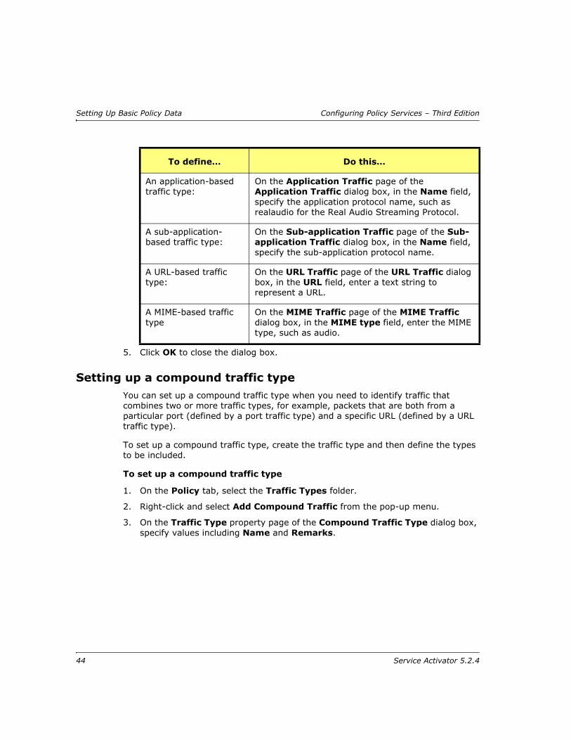
Setting Up Basic Policy Data Configuring Policy Services – Third Edition
5. Click OK to close the dialog box.
Setting up a compound traffic type You can set up a compound traffic type when you need to identify traffic that combines two or more traffic types, for example, packets that are both from a particular port (defined by a port traffic type) and a specific URL (defined by a URL traffic type).
To set up a compound traffic type, create the traffic type and then define the types to be included.
To set up a compound traffic type
1. On the Policy tab, select the Traffic Types folder.
2. Right-click and select Add Compound Traffic from the pop-up menu.
3. On the Traffic Type property page of the Compound Traffic Type dialog box, specify values including Name and Remarks.
An application-based traffic type:
On the Application Traffic page of the Application Traffic dialog box, in the Name field, specify the application protocol name, such as realaudio for the Real Audio Streaming Protocol.
A sub-application-based traffic type:
On the Sub-application Traffic page of the Sub-application Traffic dialog box, in the Name field, specify the sub-application protocol name.
A URL-based traffic type:
On the URL Traffic page of the URL Traffic dialog box, in the URL field, enter a text string to represent a URL.
A MIME-based traffic type
On the MIME Traffic page of the MIME Traffic dialog box, in the MIME type field, enter the MIME type, such as audio.
To define… Do this…
44 Service Activator 5.2.4
Configuring Policy Services – Third Edition Setting Up Basic Policy Data
To define the traffic types included in the compound traffic type
Either:
Create members of the group directly, by right-clicking the compound traffic type and choosing the appropriate Add command from the pop-up menu.
or:
If the traffic type already exists, include it in the compound traffic type by dragging and dropping.
For complete dialog box and property page descriptions, refer to the Online Help.
Setting up a traffic type groupSet up a traffic type group if you want to organize traffic types into a logical or hierarchical structure.
Traffic type groups are for administrative purposes only, and you cannot apply policy to them.
To set up a traffic type group
1. On the Policy tab, select the Traffic Types folder.
Alternatively, to add a traffic type group to an existing group, expand the Traffic Types folder and right-click the appropriate folder.
2. Select Add Traffic Group from the pop-up menu.
3. On the Traffic Type property page, enter details including Name and Remarks.
4. Click OK to close the dialog box.
To define the members of the group
Either:
Create members of the group directly, by right-clicking the group and selecting the appropriate Add command from the pop-up menu
or:
If the traffic type already exists, include it in the group by dragging and dropping
For complete dialog box and property page descriptions, refer to the Online Help.
Service Activator 5.2.4 45

Setting Up Basic Policy Data Configuring Policy Services – Third Edition
Setting up a classificationA classification is a method of categorizing traffic according to its source and/or destination and traffic type. This means, for example, that all traffic from New York can be assigned the same classification or subdivided by traffic type.
Classifications can also be collected into classification groups to create more complex criteria for classifying traffic. Classification groups enable you to group a number of traffic classifications – such as a set of routing protocols or application traffic – and apply the same class of service to them.
Classifications and classification groups can be:
Linked to a policy rule
The classification/classification group defines which traffic is acted on by the rule. (Alternatively, you can create a one-off classification within the rule definition.)
Linked to a CoS
A CoS that is linked to a classification/classification group can be associated with an MQC PHB group. The classification/classification group defines to which traffic the MQC PHB group’s policy mechanisms apply.
It is possible to create a set of classifications and classification groups by loading the advanced.policy file. The file creates the following classification groups, held in the Classifications folder on the Policy tab:
The DSCP Values classification group holds a set of classifications based on DiffServ codepoint packet marking traffic types
The IP Precedence classification group holds a set of classifications based on IP Precedence packet marking traffic types
The MPLS EXP Values classification group holds a set of classifications based on MPLS experimental bit packet marking traffic types
For information on loading policy configuration files into Service Activator see Importing policy files on page 26.
A classification group cannot be associated with more than eight DiffServ codepoint values, defined in classifications linked to the classification group. If a classification group based on more than eight codepoints is required, subclassification groups must be created and linked to a parent classification group.
46 Service Activator 5.2.4

Configuring Policy Services – Third Edition Setting Up Basic Policy Data
Using classifications with policy rules
When deciding which classifications to create, we suggest you evaluate which source and destination and traffic type combinations need to have the same policy applied to them. Create a classification for each combination and, if necessary, group those classifications. You can then associate the group with the relevant rules.
For information on associating a classification with a rule, see Defining QoS and Access Control on page 59. For an example use of classifications and classification groups, see Using classifications in rules on page 159.
Using classifications with MQC PHB groups
A classification/classification group may be linked to a CoS which, in turn, may be linked to an MQC PHB group. The treatment to be applied to traffic that belongs to the CoS is defined by the MQC PHB group.
In order to explain the options Service Activator offers for classifications/classification groups, it is necessary to refer to the configuration that is installed on the device. This includes at least one class map, generated for the CoS; a class map defines a traffic class. There are three main elements in a traffic class:
A name – taken from the CoS.
One or more match statements, generated for the classification or classification group linked to the CoS; a match statement specifies a criterion for classifying packets.
An instruction on how to evaluate the match statements – match any or match all of the match statements (described on page 48).
CoS
Classification ClassificationGroup
MQC PHB Group
Service Activator 5.2.4 47

Setting Up Basic Policy Data Configuring Policy Services – Third Edition
For example, where a classification based on a packet marking traffic type is associated with a CoS, a class map is configured containing a single match statement for that packet marking.
Only one classification or classification group may be associated with a CoS.
Match any or match all
The class map generated for a CoS may contain a number of match statements.
If a CoS is linked to a classification group, you can specify how packets are evaluated against the match criteria – whether packets must ‘match all’ of the match statements or ‘match any’.
Named or numbered Access Control Lists
Classifications based on source/destination IP address or port, and protocol result in one or more Access Control Lists (ACLs) being configured on the device. These ACLs are referenced by a match statement in the class map.
By default, Service Activator generates ACL identifiers automatically. However, you can override this and specify a name or number for an ACL.
By using aggregation – described on page 50 – you can also control the number of ACLs that are configured.
A classification provides the lowest level of classification and the match criteria for a classification is therefore always ‘match all’. You cannot change this setting.
CoS:Silver
Classification:SilverTraffic
MQC PHB Group
class-map Silver
match ip dscp
48 Service Activator 5.2.4

Configuring Policy Services – Third Edition Setting Up Basic Policy Data
Nested class maps
Service Activator always configures a class map for the CoS. A ‘nested’ class map may also be configured for a classification/classification group if both of the following apply:
The parent classification group’s match criteria is ‘match any’
The match criteria is ‘match all’ and the classification/classification group can only be expressed with multiple match statements.
The number of match statements generated depends on whether match statements for the classification or group may be aggregated with other match statements at the same level. Aggregation is described on page 50.
A class map generated for a classification/classification group is nested by a reference in a match statement in the CoS’s class map. This is illustrated in the following diagram.
CoS:Bronze
class-map Bronze
class-map DSCP 1 - Subnet 1
Classification:URL Match All
Classification:DSCP 1 Match All
A class map is configured because:
parent's classification group matchcriteria = Match Any
own match criteria = Match All andrequires multiple match statement
match class-map DSCP 1 - Subnet 1
Class map forDSCP 1 - Subnet 1
classification group referencedin CoS class map
Classification Group:Traffic Match Any
Classification Group:DSCP 1 - Subnet 1 Match All
Service Activator 5.2.4 49

Setting Up Basic Policy Data Configuring Policy Services – Third Edition
Aggregation
A classification/classification group linked to a CoS may result in a number of match statements of the same type. For example, a classification group that groups classifications based on the packet marking traffic type (DiffServ codepoint).
You can specify whether match statements of the same type are aggregated into a single match statement within the parent class map.
Service Activator uses the following rules when applying aggregation:
If a classification/classification group is a child of a classification group, the aggregation setting of the parent classification group determines whether aggregation is applied to the match statements generated for the child.
If a child classification/classification group requires an ACL and its match statements are set to aggregate by a parent classification group, the ACL identifier is taken from the parent classification group.
A classification group set to ‘match any’ may aggregate the match statements generated for a child classification group if:
— The nested classification group is also set to ‘match any’
or:
— The child classification group is set to ‘match all’ but the classification can be expressed with a single match statement and any associated ACL has a single entry
A classification group set to ‘match all’ cannot aggregate the match statements generated for a child classification/classification group
The following diagram illustrates some of these rules.
50 Service Activator 5.2.4
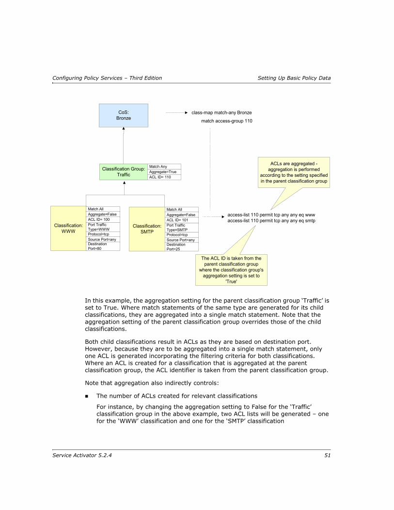
Configuring Policy Services – Third Edition Setting Up Basic Policy Data
In this example, the aggregation setting for the parent classification group ‘Traffic’ is set to True. Where match statements of the same type are generated for its child classifications, they are aggregated into a single match statement. Note that the aggregation setting of the parent classification group overrides those of the child classifications.
Both child classifications result in ACLs as they are based on destination port. However, because they are to be aggregated into a single match statement, only one ACL is generated incorporating the filtering criteria for both classifications. Where an ACL is created for a classification that is aggregated at the parent classification group, the ACL identifier is taken from the parent classification group.
Note that aggregation also indirectly controls:
The number of ACLs created for relevant classifications
For instance, by changing the aggregation setting to False for the ‘Traffic’ classification group in the above example, two ACL lists will be generated – one for the ‘WWW’ classification and one for the ‘SMTP’ classification
CoS:Bronze
class-map match-any Bronze
Classification Group:Traffic
match access-group 110
Match AnyAggregate=TrueACL ID= 110
Classification:WWW
Match AllAggregate=FalseACL ID= 100Port TrafficType=WWWProtocol=tcpSource Port=anyDestinationPort=80
Classification:SMTP
Match AllAggregate=FalseACL ID= 101Port TrafficType=SMTPProtocol=tcpSource Port=anyDestinationPort=25
access-list 110 permit tcp any any eq wwwaccess-list 110 permit tcp any any eq smtp
ACLs are aggregated -aggregation is performed
according to the setting specifiedin the parent classification group
The ACL ID is taken from theparent classification group
where the classification group'saggregation setting is set to
'True'
Service Activator 5.2.4 51
Setting Up Basic Policy Data Configuring Policy Services – Third Edition
Whether nested class maps are generated
If a classification group is a child of another classification group but its match statements are aggregated into a single match statement, no class map needs to be generated for the nested classification group
Note: For complete dialog box and property page descriptions, refer to the Online Help.
To set up a classification
1. On the Policy tab, select the Classifications folder.
Alternatively, to add a classification to an existing group, click on the classification group.
2. Right-click and select Add Classification from the pop-up menu.
The Classification dialog box opens.
3. On the Details property page, specify values including Name and Remarks.
4. On the Source/Destination property page specify the source and destination values to be included in the classification.
5. On the Traffic Type property page, select the traffic type to be classified.
6. If the classification will be used with an MQC PHB group, select the MQC property page and specify values for Aggregate match statements, Auto Generate, Numbered, and Name.
7. Click OK to close the dialog box.
To set up a classification group
1. On the Policy tab, right-click the Classifications folder.
2. Select Add Classification Group from the pop-up menu. The Classification Group dialog box appears.
3. On the Details property page, specify values including Name and Remarks.
4. If the classification group will be used with an MQC PHB group, select the MQC property page and specify some or all of Match Any, Match All, Aggregate match statements, Auto Generate, Numbered and Name.
5. Click OK.
6. Add classifications to the group by doing one of the following:
Dragging and dropping existing classifications on to the group
Creating new classifications within the group by right-clicking and selecting Add Classification from the group’s pop-up menu
52 Service Activator 5.2.4
Configuring Policy Services – Third Edition Setting Up Basic Policy Data
Setting up a date and time templateA date and time template consists of a defined time period, which can apply on specified days between any two dates. For example, you could set up a template that applies from 9:00 a.m. to 5:00 p.m. every Monday to Friday or one that applies between 3:00 p.m. and 5:30 p.m. on Tuesdays only. You can associate date and time templates with policy rules to specify that the rules are only active during certain periods.
Note: For complete dialog box and property page descriptions, refer to the Online Help.
To set up a date and time template
1. On the Policy tab, select the Date and Time Templates folder.
2. Right-click and Add Date and Time Template from the pop-up menu.
The Date and Time Template dialog box opens.
3. Enter details for Name, Active date range, Active part of day, and Active days
4. Click OK or Apply.
The defined time periods will repeat throughout the defined period of validity. For a template indicating a one-off time period, (such as 9:00 a.m. until 12:30 p.m. on 12th August) set the First and Last days to be the same.
Times must be specified to the nearest five-minute boundary.
A classification group cannot be associated with more than eight DiffServ codepoint values, defined in classifications linked to the classification group. If a classification group based on more than eight codepoints is required, subclassification groups must be created and linked to a parent classification group.
Dates and times are held in Co-ordinated Universal Time (UTC) throughout Service Activator. However, they are displayed in the local time for the workstation, adjusted for daylight savings where relevant. Remember that you may need to adjust times if rules are to apply to different time zones.
Service Activator 5.2.4 53

Setting Up Basic Policy Data Configuring Policy Services – Third Edition
Setting up IP protocolsIP protocols are used when defining traffic types by port and IP protocol. A number of commonly-used IP protocols are included in Service Activator on installation.
You should not need to change these protocol definitions, but you can view them and, if necessary, set up additional protocols for classifying network traffic.
Note: For complete dialog box and property page descriptions, refer to the Online Help.
To view an IP protocol
1. On the Policy tab, expand the IP Protocols folder.
Service Activator lists the defined IP protocols.
2. To view a protocol’s details, double-click the relevant protocol or right-click the protocol and select Properties from the pop-up menu.
The IP Protocol dialog box opens.
To add an IP protocol
1. On the Policy tab, right-click the IP Protocols folder and select Add IP Protocol from the pop-up menu.
2. Specify details including Protocol name, and Protocol number.
3. Click OK.
Setting up accountsAccounts can be used to define the users of QoS and security services and act as the source and destination points for rules.
You can define the source and destination points between which a rule applies within the rule itself, or using classifications. For information on defining classification rules see Classification rules on page 64, for defining access rules see Access rules on page 70 and for policing rules see Policing rules on page 68. For information on defining classifications, see Setting up a classification on page 46.
An account is always identified by an IP address, but may represent an individual user, a specific host computer or a subnet. You can also set up account groups that include a number of accounts of any type. You can use these groups to apply policy
If the standard IP protocols are deleted by accident, you can restore them by reloading the SharedPolicyData.policy file.
54 Service Activator 5.2.4
Configuring Policy Services – Third Edition Setting Up Basic Policy Data
to several accounts simultaneously or use them for organizational purposes only. You can also create default account groups based on the sites you have created.
Note: For complete dialog box and property page descriptions, refer to the Online Help.
To set up an account for an individual user
Set up a user account when you need to manage network traffic to or from a specific person.
1. On the Accounts tab, select the Accounts folder.
Alternatively, to add a user to an existing account group, expand the Accounts folder and select the appropriate account group. For information on creating account groups, see page 56.
2. Right-click and select Add User Account from the pop-up menu.
The User Account dialog box opens.
3. On the User Account page, enter details including First Name, Last Name, User Id, Contact, and Location.
4. On the IP Address page, enter a value for IP Address - the IP address of the user’s workstation
5. Click OK to close the dialog box.
To set up an account for a host computer
You can set up a host account when you need to manage network traffic to or from a specific host computer.
1. On the Accounts tab, select the Accounts folder.
Alternatively, to add a host to an existing account group, expand the Accounts folder and select the appropriate account group. For information on creating account groups, see page 56.
2. Right-click and select Add Host Account from the pop-up menu.
3. On the Details page, enter details including Name, and Remarks.
4. On the Host Account page, enter the IP address - the IP address of the workstation. Alternatively, you can enter the DNS name and click the DNS lookup button to look up the IP address.
5. Click OK to close the dialog box.
The user is identified by the workstation IP address. You can enter additional information if you wish, but it is not used by Service Activator.
Service Activator 5.2.4 55

Setting Up Basic Policy Data Configuring Policy Services – Third Edition
To set up an account for a subnet
Set up a subnet account when you need to manage network traffic to or from an entire subnet.
1. On the Accounts tab, select the Accounts folder.
Alternatively, to add a subnet account to an existing account group, expand the Accounts folder and select the appropriate account group. For information on creating account groups, see page 56.
2. Right-click and sellect Add Subnet Account from the pop-up menu.
3. On the Details page, enter details including Name, and Remarks.
4. On the Subnet Account page, enter details including Subnet Address and Subnet Mask.
5. Click OK to close the dialog box.
To set up an account group
Set up an account group when you have a requirement to apply policy to a number of different individuals, host computers or subnets. You can also use account groups to create a hierarchical structure for organizational purposes or to represent the structure of a company.
Setting up an account group involves creating a named group and then defining its members.
1. On the Accounts tab, select the Accounts folder.
Alternatively, to add a group as a subset of an existing account group, expand the Accounts folder and select the appropriate account group.
2. Right-click and select Add Group Account from the pop-up menu.
3. On the Details page, enter details including Name and Remarks.
4. Click OK.
5. To define the members of the group, either:
Create members of the group directly, by right-clicking the group and selecting Add User Account, Add Host Account or Add Subnet Account from the pop-up menu.
or:
If an account already exists, you can include it in the group by dragging and dropping.
56 Service Activator 5.2.4

Configuring Policy Services – Third Edition Setting Up Basic Policy Data
To define account groups automatically for defined sites
You can automatically set up default account information for the sites you have created. Suitable account group, subnet accounts and host accounts will be created, which you can edit if required.
Note that you must have already set up all relevant sites and assigned the appropriate interfaces/devices to them. An account is created for a site if the site meets the following conditions:
The site contains a device with the Access role assigned to it, or no role assigned
The device has interfaces or sub-interfaces that have the role Local or Disabled assigned to them and they are not shut down
The interfaces have subnets connected to them
From the Tools menu, select Create Site Accounts. Service Activator examines all sites that are set up. For any access router associated with a site account, it examines the segments and hosts and attempts to create a set of meaningful accounts:
For each site, an account group is created. The group is given the same name as the site.
For each segment that has host systems defined, an account group is created. The group is given the name Segment IP address hosts. Within this group, a host account is created for each host system on the segment. The name of the host is used as the name of the account.
For a segment that does not have host systems defined, a subnet account is created. The IP address of the segment is used as the name of the account.
The new sites are listed on the Accounts tab beneath the Accounts folder.
Service Activator 5.2.4 57

Setting Up Basic Policy Data Configuring Policy Services – Third Edition
58 Service Activator 5.2.4

Configuring Policy Services – Third Edition Defining QoS and Access Control
Chapter 3
Defining QoS and Access Control
This chapter describes the rule types that feature in Service Activator. The chapter:
Provides an overview of each rule type and its function
Describes where rules can be applied
Gives detailed information for creating classification, policing and access rules
Describes how to implement rules
Explains how to check the status of implemented rules
Describes how to manage and disable rules
Service Activator 5.2.4 59

Defining QoS and Access Control Configuring Policy Services – Third Edition
IntroductionRules are one of the building blocks you use to create a QoS or security policy. You can use rules to:
Mark traffic and optionally manage bandwidth – classification rules
Police the bandwidth used by a particular traffic type or classification and specify the treatment for traffic that conforms to or exceeds the bandwidth requirements – policing rules
Implement security by permitting or denying network traffic – access rules
You can apply rules to any policy target – that is, any network component, a customer, site or VPN – and you can apply any type of rule at any point in the network. For example, you can apply a classification rule to a device at the network edge or in the core. However, some general guidelines for deployment are:
Use classification rules at the outbound interface of devices at the network edge – that is, CE (access) devices.
Use policing rules at the outbound interface of devices at the network edge or inbound interfaces at the core edge – that is, CE (access) or PE (gateway) devices. Policing at CE devices is preferable as it reduces traffic at the earliest possible point. However, if the CE device is not managed by the service provider, this may not be possible.
Use access rules at the network edge – that is, CE (access) devices. Access rules can also be used within the core network to protect specific servers.
You can specify whether a rule applies to an interface’s inbound or outbound traffic, or traffic in both directions.
The type of traffic a rule applies to can be defined as a one-off classification within the rule itself, based on source and destination address and traffic type. Alternatively, if you have created standalone traffic classifications, you can associate any number of classifications or classification groups with a rule. For information on defining classifications, see Setting up a classification on page 46.
The ability to install a rule is dependent on an interface’s capabilities. For example, an access rule can only be installed on an interface whose capabilities show support for ‘Access’. For more information, see the Network Discovery and Basic Setup guide.
60 Service Activator 5.2.4
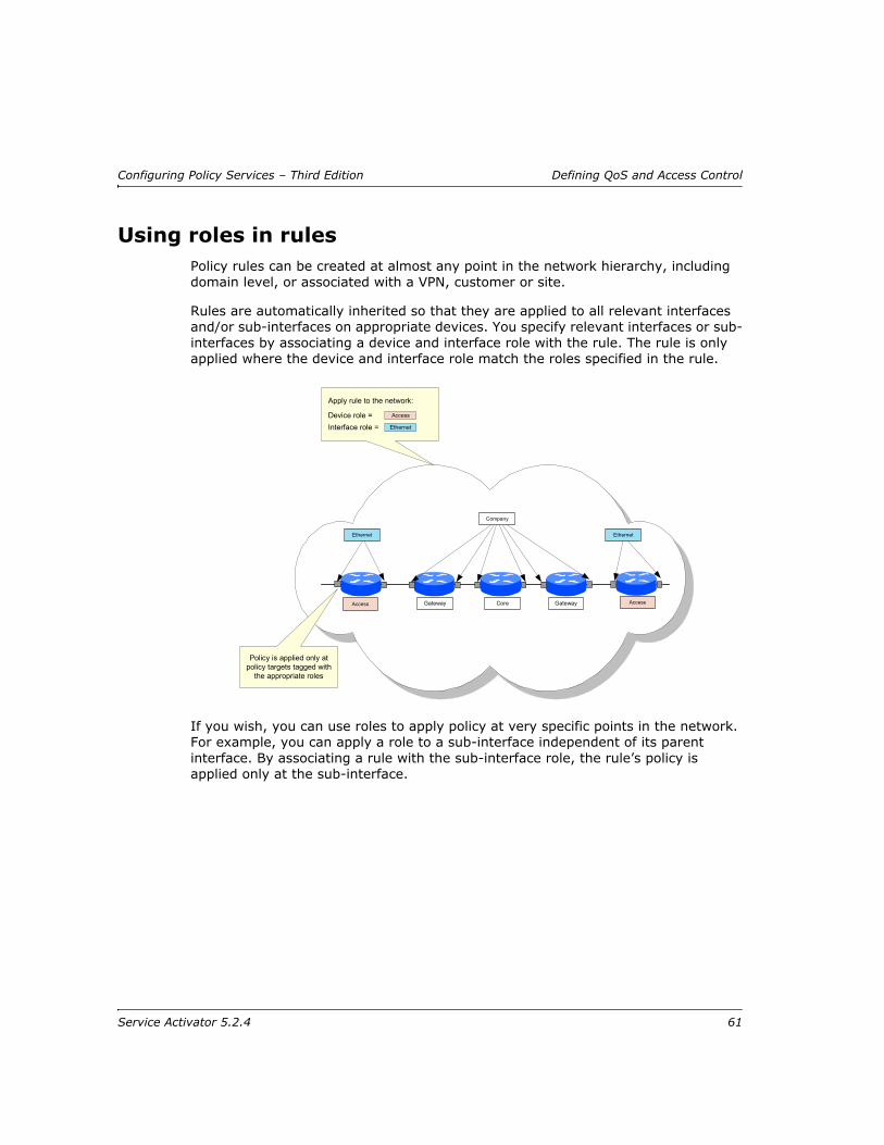
Configuring Policy Services – Third Edition Defining QoS and Access Control
Using roles in rulesPolicy rules can be created at almost any point in the network hierarchy, including domain level, or associated with a VPN, customer or site.
Rules are automatically inherited so that they are applied to all relevant interfaces and/or sub-interfaces on appropriate devices. You specify relevant interfaces or sub-interfaces by associating a device and interface role with the rule. The rule is only applied where the device and interface role match the roles specified in the rule.
If you wish, you can use roles to apply policy at very specific points in the network. For example, you can apply a role to a sub-interface independent of its parent interface. By associating a rule with the sub-interface role, the rule’s policy is applied only at the sub-interface.
Ethernet
Access
Policy is applied only atpolicy targets tagged with
the appropriate roles
Gateway GatewayCore Access
Ethernet
Company
Device role = Access
Apply rule to the network:
EthernetInterface role =
Service Activator 5.2.4 61
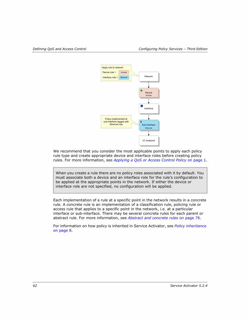
Defining QoS and Access Control Configuring Policy Services – Third Edition
We recommend that you consider the most applicable points to apply each policy rule type and create appropriate device and interface roles before creating policy rules. For more information, see Applying a QoS or Access Control Policy on page 1.
Each implementation of a rule at a specific point in the network results in a concrete rule. A concrete rule is an implementation of a classification rule, policing rule or access rule that applies to a specific point in the network, i.e. at a particular interface or sub-interface. There may be several concrete rules for each parent or abstract rule. For more information, see Abstract and concrete rules on page 76.
For information on how policy is inherited in Service Activator, see Policy inheritance on page 8.
When you create a rule there are no policy roles associated with it by default. You must associate both a device and an interface role for the rule’s configuration to be applied at the appropriate points in the network. If either the device or interface role are not specified, no configuration will be applied.
VC endpoint
Network
Policy implemented atsub-interface tagged with
Ethernet role
Interface
Sub-interface
Device
Apply rule to network:
EthernetInterface role =
Device role = Access
Access
Ethernet
62 Service Activator 5.2.4
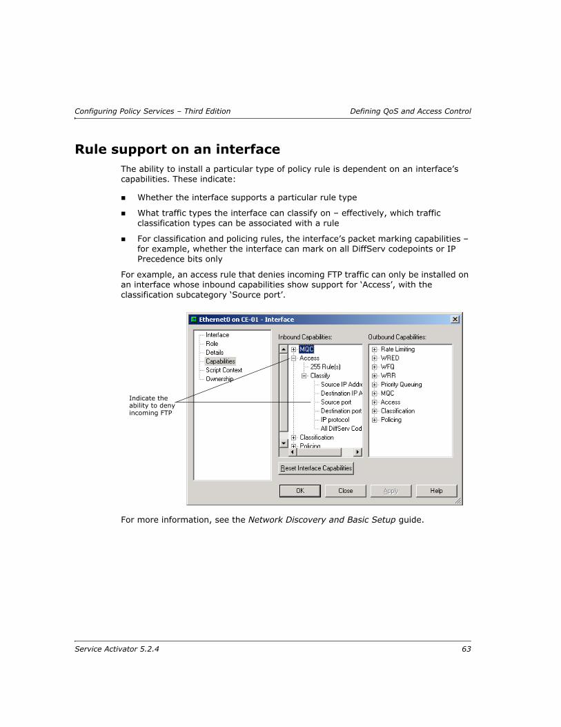
Configuring Policy Services – Third Edition Defining QoS and Access Control
Rule support on an interfaceThe ability to install a particular type of policy rule is dependent on an interface’s capabilities. These indicate:
Whether the interface supports a particular rule type
What traffic types the interface can classify on – effectively, which traffic classification types can be associated with a rule
For classification and policing rules, the interface’s packet marking capabilities – for example, whether the interface can mark on all DiffServ codepoints or IP Precedence bits only
For example, an access rule that denies incoming FTP traffic can only be installed on an interface whose inbound capabilities show support for ‘Access’, with the classification subcategory ‘Source port’.
For more information, see the Network Discovery and Basic Setup guide.
Indicate the ability to deny incoming FTP
Service Activator 5.2.4 63
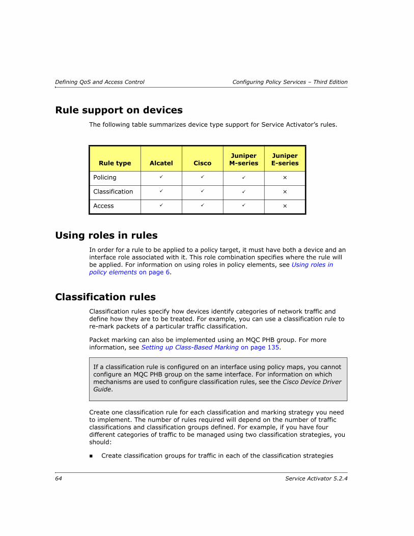
Defining QoS and Access Control Configuring Policy Services – Third Edition
Rule support on devicesThe following table summarizes device type support for Service Activator’s rules.
Using roles in rulesIn order for a rule to be applied to a policy target, it must have both a device and an interface role associated with it. This role combination specifies where the rule will be applied. For information on using roles in policy elements, see Using roles in policy elements on page 6.
Classification rulesClassification rules specify how devices identify categories of network traffic and define how they are to be treated. For example, you can use a classification rule to re-mark packets of a particular traffic classification.
Packet marking can also be implemented using an MQC PHB group. For more information, see Setting up Class-Based Marking on page 135.
Create one classification rule for each classification and marking strategy you need to implement. The number of rules required will depend on the number of traffic classifications and classification groups defined. For example, if you have four different categories of traffic to be managed using two classification strategies, you should:
Create classification groups for traffic in each of the classification strategies
Rule type Alcatel CiscoJuniper M-series
Juniper E-series
Policing ×
Classification ×
Access ×
If a classification rule is configured on an interface using policy maps, you cannot configure an MQC PHB group on the same interface. For information on which mechanisms are used to configure classification rules, see the Cisco Device Driver Guide.
64 Service Activator 5.2.4
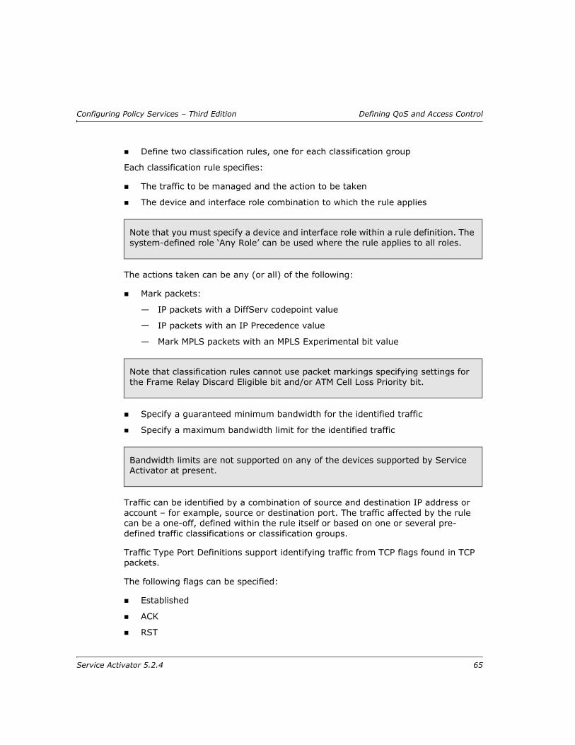
Configuring Policy Services – Third Edition Defining QoS and Access Control
Define two classification rules, one for each classification group
Each classification rule specifies:
The traffic to be managed and the action to be taken
The device and interface role combination to which the rule applies
The actions taken can be any (or all) of the following:
Mark packets:
— IP packets with a DiffServ codepoint value
— IP packets with an IP Precedence value
— Mark MPLS packets with an MPLS Experimental bit value
Specify a guaranteed minimum bandwidth for the identified traffic
Specify a maximum bandwidth limit for the identified traffic
Traffic can be identified by a combination of source and destination IP address or account – for example, source or destination port. The traffic affected by the rule can be a one-off, defined within the rule itself or based on one or several pre-defined traffic classifications or classification groups.
Traffic Type Port Definitions support identifying traffic from TCP flags found in TCP packets.
The following flags can be specified:
Established
ACK
RST
Note that you must specify a device and interface role within a rule definition. The system-defined role ‘Any Role’ can be used where the rule applies to all roles.
Note that classification rules cannot use packet markings specifying settings for the Frame Relay Discard Eligible bit and/or ATM Cell Loss Priority bit.
Bandwidth limits are not supported on any of the devices supported by Service Activator at present.
Service Activator 5.2.4 65

Defining QoS and Access Control Configuring Policy Services – Third Edition
URG
PSH
SYN
FIN
Further classifications based on ICMP protocol can be done using the Messages drop-down menu. This menu is enabled only when ICMP is selected as IP protocol on the Port Traffic page.
These are the available ICMP protocol options:
EchoRequest
EchoReply
TTLExceeded
Unreachable
Redirect
TTL-Exceed
Time-exceeded
PacketTooBig
SourceQuench
ICMP protocol options are enabled only if ICMP is selected as IP protocol on Port Traffic page.
Optionally, classification rules can be made conditional on a date or time.
You can copy an existing classification rule to other policy targets and update values for multiple roles. For more information see Copying rules on page 75 and Updating multiple rules on page 73.
To set up a classification rule
Note: For complete dialog box and property page descriptions, refer to the Online Help.
1. Select the object to which the rule applies.
You can apply a classification rule to any policy target.
2. Right-click and select Add Classification Rule from the pop-up menu.
3. On the Classification Rule page, enter values including Name, Quality of Service, Direction, and Rule Status.
66 Service Activator 5.2.4

Configuring Policy Services – Third Edition Defining QoS and Access Control
4. Under Classification either specify that the rule applies to traffic defined within the rule or to one or several pre-defined classifications or classification groups:
5. To set a guaranteed bandwidth level to be assigned to the traffic, select the Guarantee checkbox and enter a value (in Kbits/s).
6. If the traffic classification to which the rule applies is a one-off, defined within the rule:
Select the Classification page and specify the source and destination points between which the rule is applied.
7. If the rule applies to one or more pre-defined traffic classifications or classification groups:
Select the Classification page and select the relevant classifications or classification groups.
8. Select the Role page and select the device and interface roles to which the rule applies.
You must specify both a device and an interface role. The system-defined Any Role can be used to apply the rule to any device or interface tagged with a role.
9. On the Marking page, specify how the rule is to mark packets. Either:
— Select the Packet Marking with which identified packets are to be marked.
or:
— Select an 802.1p User Priority
10. If you want the classification rule to apply at a particular date or time, select the Date and Time page.
You can select from any previously set up date and time template listed in the Name combo box. Alternatively, you can select Local from the combo box and enter details directly of the date and time that the policy is to apply.
11. Click OK to close the dialog box, and save the rule.
802.1p User Priority values are not currently used by any supported device types.
The rule is not implemented until it is propagated to the network by committing the transaction. For more information see the Network Discovery and Basic Setup guide.
Service Activator 5.2.4 67

Defining QoS and Access Control Configuring Policy Services – Third Edition
For details of how to check the implemented rules, see Checking implemented rules on page 76.
For detailed information on marking on Cisco devices, see the Cisco Device Driver Guide.
Policing rulesPolicing rules specify one or more traffic classes to be policed, their bandwidth allocation and the action to take for traffic that conforms to or exceeds the specified bandwidth. For example, traffic that exceeds the bandwidth requirements can be dropped or re-marked with a lower DiffServ codepoint.
Policing rules can be associated with any policy target.
Depending on how your system is configured, you may need to create one or a number of policing rules for each traffic class to be managed. By grouping traffic classes into traffic classification groups, you may be able to minimize the number of rules required. For information on defining traffic classifications and classification groups, see Setting up a classification on page 46.
Each policing rule specifies the traffic to be policed and the action to be taken.
Traffic to be policed can be identified by a combination of source and destination IP address or account and traffic type – for example, source or destination port. The traffic class to be policed can be a one-off, defined within the rule itself or based on one or more pre-defined traffic classifications or classification groups.
The following bandwidth requirements can be set:
Committed rate permitted
Normal burst size permitted
Excess burst size permitted
The committed rate can be specified on its own or in combination with normal burst size and excess burst size.
For Cisco device configuration these values directly reflect the CAR parameters and should be set to a multiple of 8,000. The driver silently rounds the value down to the nearest multiple of 8000.
Policing can also be implemented using an MQC PHB group. For more information see Setting up Class-Based Policing on page 125.
68 Service Activator 5.2.4

Configuring Policy Services – Third Edition Defining QoS and Access Control
Service Activator configures an ACL to identify the traffic policed by the rule. By default, Service Activator generates the ACL number but you can override this and specify a number.
Optionally, policing rules can be made conditional on a date or time.
Note: For complete dialog box and property page descriptions, refer to the Online Help.
To set up a policing rule
1. Select the object to which the rule applies.
You can apply a policing rule to any policy target.
2. Right-click and select Add Policing Rule from the pop-up menu.
3. On the Policing Rule page, enter details including Name, Bandwidth Requirements, and Direction for the rule.
4. Under Classification select the Local Classification checkbox to specify source/destination and traffic type within the rule or clear it to associate the rule with one or several pre-defined classifications or classification groups
5. If you wish to specify the number of the ACL generated for the policing rule, select Value under Access Control List and specify a value.
6. If the traffic class to which the rule applies is a one-off, defined within the rule:
Select the Classification page and specify Source, Destination, and Traffic Type.
7. If the rule applies to one or more pre-defined traffic classifications or classification groups, select the Classification page and select the relevant classifications or classification groups.
8. Select the Role page and select the device and interface roles to which the rule applies.
You must specify both a device and an interface role. The system-defined Any Role can be used to apply the rule to any device or interface tagged with a role.
9. On the Action page, define the action to be taken for conforming and non-conforming traffic choosing from Drop, Transmit, Continue and Re-Mark as in the Conform Action and Exceed Action panels.
Re-marked packets may be treated differently at subsequent routers.
Note that policing rules cannot use packet markings specifying settings for the Frame Relay Discard Eligible bit and/or ATM Cell Loss Priority bit.
Service Activator 5.2.4 69
Defining QoS and Access Control Configuring Policy Services – Third Edition
10. Select the Role page and select the device and interface roles to which the rule applies.
You must specify both a device and an interface role. The system-defined Any Role can be used to apply the rule to any device or interface tagged with any role.
11. If you want the rule to apply at a particular date or time, select the Date and Time page.
You can select from any previously set up date and time template listed in the Name combo box. Alternatively, you can select Local from the combo box and enter details directly of the date and time that the policy is to apply.
12. Click OK to close the dialog box, and save the rule.
For details of how to check the implemented rules, see Checking implemented rules on page 76.
Access rulesAccess rules (or filters) are used to provide network security by explicitly denying or permitting access by identified traffic.
Traffic can be identified by a combination of source and destination IP address or account and traffic type – for example, source or destination port. The traffic affected by the rule can be a one-off, defined within the rule itself or based on one or more pre-defined traffic classifications.
Depending on how your system is configured, you may need to create one or several access rules for each traffic class to be managed. By grouping traffic classes into traffic classification groups, you may be able to minimize the number of rules required. For information on defining traffic classifications and classification groups, see Setting up a classification on page 46.
The identified traffic can be denied or permitted access. Each rule can apply to inbound traffic only, outbound traffic only or both.
For Re-Mark and Continue to work correctly, you need to set up several policing rules in a logical sequence.
The rule is not implemented until it is propagated to the network by committing the transaction. For more information see the Network Discovery and Basic Setup guide.
70 Service Activator 5.2.4

Configuring Policy Services – Third Edition Defining QoS and Access Control
Optionally, access rules can be made conditional on the a date or time.
Note: For complete dialog box and property page descriptions, refer to the Online Help.
To set up an access rule
1. Select the object to which the rule applies.
You can apply an access rule to any policy target.
2. Right-click and select Add Access Rule from the pop-up menu.
The Access Rule dialog box opens.
3. Under ACL type, specify whether Named or Numbered ACls are to be generated. Enter a number in the respective fields or select Generate to use a system generated name or number.
4. Select or Clear the Management rule override check box to avoid automatic creation of ACL rules. ACL rules are automatically generated to assure SNMP and Telnet access from IPSA to the CE.
5. On the Access Rule page of the Access Rule dialog box, enter values including Name, Action (Deny, Permit), Direction (In, Out), and Classification.
6. If Classification was set to Local Classification, select the Classification page and specify the source and destination points between which the rule is applied. Otherwise, select the Classification page and select the relevant classifications or classification groups.
7. Select the Role page and select the device and interface roles to which the rule applies.
You must specify both a device and an interface role. The system-defined Any Role can be used to apply the rule to any device or interface tagged with any role.
8. If you want the access rule to apply at a particular date or time, select the Date and Time page.
In the Name field, you can choose from any previously set up date and time template listed in the pull-down menu. Alternatively, you can select Local from the combo box and enter details directly of the date and time that the policy is to apply.
9. Click OK to close the dialog box.
Using the ‘deny’ classification in Cisco ACLsOn Cisco devices, Service Activator supports the ability to process or block/ignore traffic by means of exclusion. In other words, Classification objects (classifiers) can
Service Activator 5.2.4 71

Defining QoS and Access Control Configuring Policy Services – Third Edition
be created which match traffic to be excluded from further processing. For example, you can define a set of criteria so that all traffic that does not match the criteria will have QoS applied and traffic that does match the criteria will not.
The exclusion capability corresponds to the creation of Cisco ACLs employing the deny keyword. When Cisco ACLs are evaluated, processing of classification statements stops when the first match is found. Therefore, the ordering of entries in Service Activator Classification objects is of high importance. New capabilities in the Service Activator user interface support the specification of entry order in these objects.
Example ACL using the Deny keyword:
access-list 180 deny ip any any
The deny keyword is an instruction to block all traffic that matches the criteria in the ACL statement. In this example, the device blocks all IP-type traffic to which access-list 180 is applied.
User interface
The Service Activator user interface has been updated to support the deny action in Classification objects.
The Classification dialog box, Details property page, now contains two new radio buttons and two new checkboxes:
Include - the traffic that matches the specified criteria in the classifier is explicitly included in the processing applied to the classifier. This selection corresponds to the permit keyword in Cisco ACLs.
Exclude - the traffic that matches the specified criteria in the classifier is explicitly excluded in the processing applied to the classifier. This selection corresponds to the deny keyword in Cisco ACLs.
Log - Enables or disables Cisco ACL logging. Headers of packets affected by the access rule are stored in the routing engine and can be displayed using the show log command.
Note: Enabling ACL logging may negatively affect router performance as:
Processor power may be used to perform the logging
Log files may impact available disk space
Fragments - When selected, non-initial packet fragments are included for matching. This selection corresponds to the Fragments parameter in Cisco ACLs.
72 Service Activator 5.2.4

Configuring Policy Services – Third Edition Defining QoS and Access Control
Updating multiple rulesYou can update several rules simultaneously. The rules must be defined at the same point in the network – that is, you must be able to list and select them in the details pane.
You can apply a new date and time template to any rule. For classification rules, you can also re-specify the packet marking to be applied.
To update multiple rules
1. Double-click on the relevant object – any policy target – from the hierarchy tree or the topology map.
The configuration that applies at the selected level is listed in the Details pane - select the relevant tab.
2. Select several abstract rules whose values you want to set.
Service Activator 5.2.4 73

Defining QoS and Access Control Configuring Policy Services – Third Edition
Abstract rules are displayed on a white background. If a rule has a gray background, it has been inherited from a higher point in the hierarchy indicated by the Level column.
3. From the pop-up menu select Properties.
The Properties dialog box opens. It contains a subset of the property pages that are available for a single rule.
Note that, if you have included a concrete rule in the selection, no property pages are displayed on the Properties dialog box. Deselect the concrete rule to display the dialog box correctly.
4. Select the relevant tabs and specify the values you wish to apply.
5. Click OK.
The values are applied and the new values displayed in the rule list.
Note that only user-defined templates are available for selection on the Date and Time property page when updating multiple rules. You can only apply the default Local setting to individual rules.
74 Service Activator 5.2.4

Configuring Policy Services – Third Edition Defining QoS and Access Control
Copying rulesYou can copy one or more rules from one policy target to another. Rules may already be applied to the target object. To prevent naming conflicts, the copied rule is named as follows:
If there is no naming conflict between the copied and the existing rules, the rule is copied to the target object with the same name.
If the copied rule conflicts with an existing rule name, the rule is copied with the text ‘Copy of’ preceding the rule name. If subsequent copies are made, the copy number is incremented – that is, ‘Copy (n) of’ where n is the copy number.
Some of the values associated with the rule may need to be edited after copying. For example, a different date and time template may need to be selected.
You cannot copy classification rules from one domain to another.
To copy rules using menu commands
1. List an object’s rules in the details pane and select one or more rules to be copied.
2. From the Edit menu, select Copy.
3. Select the target object, and from the Edit menu select Paste.
To copy rules using drag and drop
1. List an object’s rules in the details pane.
2. Open a new window for the target object and from the Window menu select Tile.
3. List the relevant rules for the target object in the details pane. Ensure that there is space at the end of the rule list.
4. Select one or more rules to be copied from the source object and drag them to the target object’s details pane.
You must drag the rules on to white space in the target window.
Editing the values associated with a copied rule may result in two rules of the same name that have different values.
Service Activator 5.2.4 75
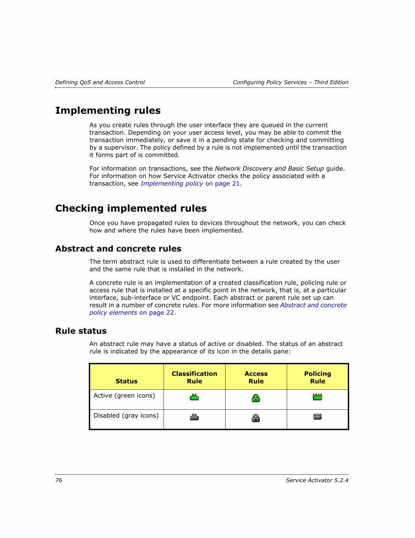
Defining QoS and Access Control Configuring Policy Services – Third Edition
Implementing rulesAs you create rules through the user interface they are queued in the current transaction. Depending on your user access level, you may be able to commit the transaction immediately, or save it in a pending state for checking and committing by a supervisor. The policy defined by a rule is not implemented until the transaction it forms part of is committed.
For information on transactions, see the Network Discovery and Basic Setup guide. For information on how Service Activator checks the policy associated with a transaction, see Implementing policy on page 21.
Checking implemented rulesOnce you have propagated rules to devices throughout the network, you can check how and where the rules have been implemented.
Abstract and concrete rulesThe term abstract rule is used to differentiate between a rule created by the user and the same rule that is installed in the network.
A concrete rule is an implementation of a created classification rule, policing rule or access rule that is installed at a specific point in the network, that is, at a particular interface, sub-interface or VC endpoint. Each abstract or parent rule set up can result in a number of concrete rules. For more information see Abstract and concrete policy elements on page 22.
Rule statusAn abstract rule may have a status of active or disabled. The status of an abstract rule is indicated by the appearance of its icon in the details pane:
StatusClassification
RuleAccess Rule
Policing Rule
Active (green icons)
Disabled (gray icons)
76 Service Activator 5.2.4

Configuring Policy Services – Third Edition Defining QoS and Access Control
A concrete rule may have the following status:
Inactive – the rule has been applied to an interface but has not yet been propagated to proxy agents.
Active – the rule has been propagated to a proxy agent but is not installed on a device at present.
Conflict – the rule conflicts with an existing rule or fails validation, for example, the action performed by a rule is not supported by an interface.
Rejected – the proxy agent failed to install the rule and it has been discarded.
Installed – the rule has been successfully installed on the designated device.
The following icons are used to show the status of concrete rules:
Viewing implemented rulesAt any one time, a number of rules may be listed for a policy target – particularly as rules can be applied to various levels of both the logical and the physical hierarchy and applied via a process of inheritance. For information on inheritance, see Policy inheritance on page 8.
The listed rules may have originated at a higher point in the hierarchy. Service Activator uses color to indicate whether the rule is abstract or concrete. For more information, see Abstract and concrete policy elements on page 22.
Note that you can also view summary information for rules (see page 81) as well as searching for concrete rules by type and status (see page 82).
Status Classification Rule Access Rule Policing Rule
Inactive
Active
Conflict
Rejected
Installed
Service Activator 5.2.4 77
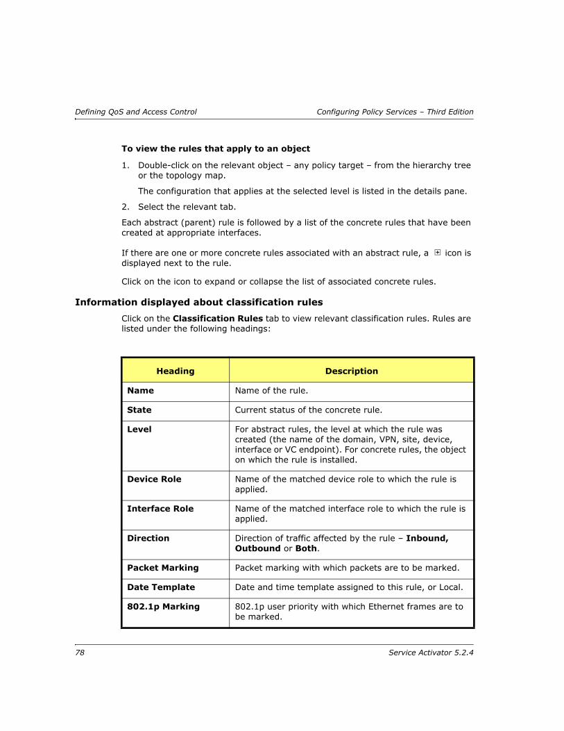
Defining QoS and Access Control Configuring Policy Services – Third Edition
To view the rules that apply to an object
1. Double-click on the relevant object – any policy target – from the hierarchy tree or the topology map.
The configuration that applies at the selected level is listed in the details pane.
2. Select the relevant tab.
Each abstract (parent) rule is followed by a list of the concrete rules that have been created at appropriate interfaces.
If there are one or more concrete rules associated with an abstract rule, a icon is displayed next to the rule.
Click on the icon to expand or collapse the list of associated concrete rules.
Information displayed about classification rules
Click on the Classification Rules tab to view relevant classification rules. Rules are listed under the following headings:
Heading Description
Name Name of the rule.
State Current status of the concrete rule.
Level For abstract rules, the level at which the rule was created (the name of the domain, VPN, site, device, interface or VC endpoint). For concrete rules, the object on which the rule is installed.
Device Role Name of the matched device role to which the rule is applied.
Interface Role Name of the matched interface role to which the rule is applied.
Direction Direction of traffic affected by the rule – Inbound, Outbound or Both.
Packet Marking Packet marking with which packets are to be marked.
Date Template Date and time template assigned to this rule, or Local.
802.1p Marking 802.1p user priority with which Ethernet frames are to be marked.
78 Service Activator 5.2.4

Configuring Policy Services – Third Edition Defining QoS and Access Control
Only the State, Level and ID appear for concrete classification rules.
Information displayed about access rules
Click on the Access Rules tab to view relevant access rules. Rules are listed under the following headings:
Guaranteed The level of bandwidth (in Kbits/s) guaranteed for the traffic.
Limit The maximum bandwidth (in Kbits/s) that can be allocated to traffic.
ID The internal ID number by which the concrete rule is identified.
Owner If ownership of the rule has been specified, the owner’s username.
OwnerGroup The group to which the owner belongs.
Heading Description
Heading Description
Name Name of the rule.
State Current status of the concrete rule.
Level For abstract rules, the level at which the rule was created (the name of the domain, VPN, site, device, interface or VC endpoint). For concrete rules, the interface or VC endpoint on which the rule is installed.
Device Role Name of the matched device role to which the rule is applied.
Interface Role Name of the matched interface role to which the rule is applied.
Direction Direction of traffic affected by rule - Inbound, Outbound or Both.
Access Deny if the rule denies access or Permit if the rule permits access.
Service Activator 5.2.4 79
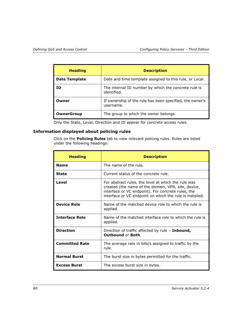
Defining QoS and Access Control Configuring Policy Services – Third Edition
Only the State, Level, Direction and ID appear for concrete access rules.
Information displayed about policing rules
Click on the Policing Rules tab to view relevant policing rules. Rules are listed under the following headings:
Date Template Date and time template assigned to this rule, or Local.
ID The internal ID number by which the concrete rule is identified.
Owner If ownership of the rule has been specified, the owner’s username.
OwnerGroup The group to which the owner belongs.
Heading Description
Heading Description
Name The name of the rule.
State Current status of the concrete rule.
Level For abstract rules, the level at which the rule was created (the name of the domain, VPN, site, device, interface or VC endpoint). For concrete rules, the interface or VC endpoint on which the rule is installed.
Device Role Name of the matched device role to which the rule is applied.
Interface Role Name of the matched interface role to which the rule is applied.
Direction Direction of traffic affected by rule – Inbound, Outbound or Both.
Committed Rate The average rate in bits/s assigned to traffic by the rule.
Normal Burst The burst size in bytes permitted for the traffic.
Excess Burst The excess burst size in bytes.
80 Service Activator 5.2.4
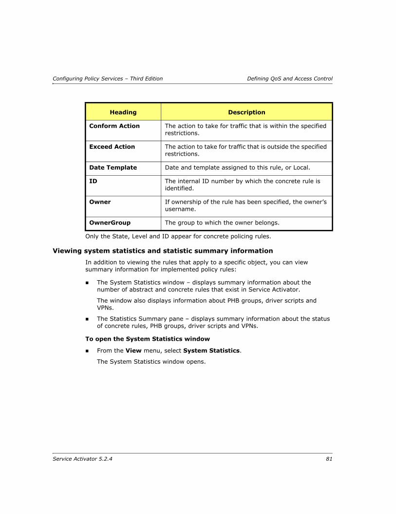
Configuring Policy Services – Third Edition Defining QoS and Access Control
Only the State, Level and ID appear for concrete policing rules.
Viewing system statistics and statistic summary information
In addition to viewing the rules that apply to a specific object, you can view summary information for implemented policy rules:
The System Statistics window – displays summary information about the number of abstract and concrete rules that exist in Service Activator.
The window also displays information about PHB groups, driver scripts and VPNs.
The Statistics Summary pane – displays summary information about the status of concrete rules, PHB groups, driver scripts and VPNs.
To open the System Statistics window
From the View menu, select System Statistics.
The System Statistics window opens.
Conform Action The action to take for traffic that is within the specified restrictions.
Exceed Action The action to take for traffic that is outside the specified restrictions.
Date Template Date and template assigned to this rule, or Local.
ID The internal ID number by which the concrete rule is identified.
Owner If ownership of the rule has been specified, the owner’s username.
OwnerGroup The group to which the owner belongs.
Heading Description
Service Activator 5.2.4 81

Defining QoS and Access Control Configuring Policy Services – Third Edition
To display the Statistics Summary pane
From the View menu, select Statistics Summary.
The Statistics Summary pane is displayed.
Locating concrete policy elements
You can search for concrete policy elements – rules, PHB groups and driver scripts – by type and state.
To perform a concrete object search
1. Choose Concrete Find from the Tools menu.
The Concrete Find dialog box opens.
82 Service Activator 5.2.4

Configuring Policy Services – Third Edition Defining QoS and Access Control
2. Select the Match Object Type checkbox and select a concrete object type from the pull-down list.
3. If you wish to restrict the search by status, select the Match Object State checkbox and select a state from the pull-down list.
4. Click Find to start the search.
Service Activator searches the object model for concrete objects that match the search criteria.
For each found concrete policy element, the following details are listed:
— Name of the object
— State – the object's status
— Level – the name of the topology object at which the concrete object applies
— Direction – whether the object is applied inbound or outbound to the interface
— ID – the Service Activatorr object ID
— Domain – the name of the domain
Service Activator 5.2.4 83

Defining QoS and Access Control Configuring Policy Services – Third Edition
5. Double-click on a found concrete object to view the point at which it applies in the hierarchy pane and details of the rule in the details pane.
If concrete rules are not createdIf no concrete rules are listed for an abstract rule, check that the following conditions have been implemented:
The correct device and interface roles have been associated with the rule and assigned to the relevant policy targets – see Using roles in policy elements on page 6 and the Network Discovery and Basic Setup guide.
Devices to which the rule should apply are managed – see the Network Discovery and Basic Setup guide.
Managing rules
Changing the sequence order of rulesAt any one time, a number of rules of a specific type (classification, access or policing rules) may apply to a particular interface – particularly as rules can be applied to various different levels and applied via a process of inheritance.
84 Service Activator 5.2.4

Configuring Policy Services – Third Edition Defining QoS and Access Control
The abstract and inherited rules that apply to a policy target are listed in the following order:
Abstract rules – rules created at the object
Inherited rules – rules that have been inherited from an object higher in the hierarchy
Inherited rules are further subdivided according to where the corresponding abstract rule was applied. For example, rules inherited from devices are grouped together.
The order in which rules are listed in the details pane is important as this defines the order in which rules are checked against packets on that interface. The first rule that matches the packet is applied. Therefore you must ensure that rules appear in the correct order – for example, you need to ensure that a more general rule does not appear before a specific rule that would therefore never be checked.
The initial order reflects the order in which the rules were created, but you can change the order if required, by dragging and dropping rules to a new position in the list.
How rule conflicts are avoidedIt is potentially possible for two rules of the same type to be in conflict if there is any overlap in the defined traffic. Inadvertent conflicts may occur where rules are created at various levels (domain, customer, VPN, site, device, interface or VC endpoints). For example, an access rule defined at a high-level object might apply to all port-based traffic types, while an access rule defined at a lower-level object applies to a specific port.
Potential rule conflicts are dealt with automatically by Service Activator by a process of rule ordering. At each interface, Service Activator checks the rules in a strict sequence and rules are not applied if they would result in a conflict. Rules created at a lower level override those created at a higher level - for example, a classification rule created at a specific interface overrides one created for the whole domain. Where multiple rules apply at any one level, they are checked in their defined sequence order, which can be changed.
You cannot move inherited rules above abstract rules – this means that abstract rules always override inherited rules.
Service Activator 5.2.4 85

Defining QoS and Access Control Configuring Policy Services – Third Edition
The priority levels are as follows, where the lower the number the higher the priority:
For example, a rule that applies to a device takes precedence over a rule applied at the domain level. In the case of PHB groups, only one PHB group can be applied to any one interface, so the highest priority PHB group in the list is applied, and others that may apply are ignored.
Disabling rulesYou can disable an abstract rule applied to an object at any time by selecting the Disable checkbox on the rule property page at the object level.
Object Priority
Root network 15
Network 14
Domain 12
Customer 10
VPN 8
Site 6
Device 4
Interface 3
Sub-interface 2
VC endpoint 1
86 Service Activator 5.2.4
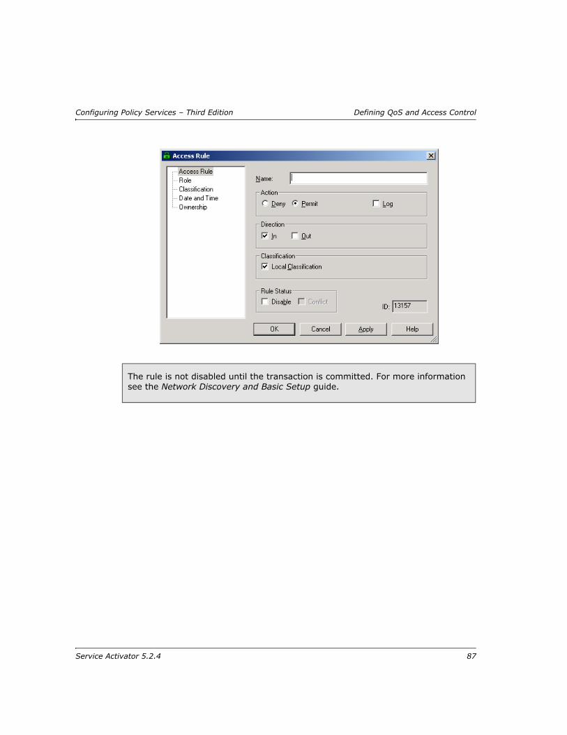
Configuring Policy Services – Third Edition Defining QoS and Access Control
The rule is not disabled until the transaction is committed. For more information see the Network Discovery and Basic Setup guide.
Service Activator 5.2.4 87

Defining QoS and Access Control Configuring Policy Services – Third Edition
88 Service Activator 5.2.4

Configuring Policy Services – Third Edition Defining Standard PHB Groups
Chapter 4
Defining Standard PHB Groups
This chapter describes how to implement queuing and traffic shaping mechanisms in the network using standard PHB groups. The chapter:
Provides an overview of standard PHB groups and the queuing and traffic shaping mechanisms that can be implemented using Service Activator
Highlights points you should consider before setting up standard PHB groups
For information on defining MQC PHB groups, see Chapter 5. For details on implementing and managing PHB groups, see Chapter 6.
Service Activator 5.2.4 89
Defining Standard PHB Groups Configuring Policy Services – Third Edition
IntroductionA PHB (Per Hop Behavior) group provides a way of managing traffic at specific interfaces by implementing a device-specific queuing or traffic shaping mechanism. Standard PHB groups manage traffic in one of two ways:
Class-of-service mechanisms allow you to define different priorities or bandwidth allocations for each class of service that will be used in your network. Examples include configuring WRR (Weighted Round Robin) and Priority Queuing.
VC mechanisms allow you to set up ATM and Frame Relay-specific traffic shaping at the VC endpoint level. These mechanisms apply to all traffic on the endpoint, irrespective of class of service.
A PHB group can be applied to a network component (such as a network, device or interface) or to a customer, site or VPN. As for any other policy element, the policy targets that a PHB group actually applies to are controlled using policy roles and the inheritance model.
Within Service Activator there are no restrictions on where a PHB group can be applied. For example, you can apply a WRR PHB group to a device at the network edge or in the network core.
MQC PHB groupsMQC (Modular QoS CLI) PHB groups allow you to implement Cisco’s simplified configuration of policy mechanisms and actions for traffic queuing, shaping, policing, congestion avoidance and re-marking on the interfaces of Cisco routers and switches. You can specify several different QoS mechanisms for different classes of service associated with the same MQC PHB group.
MQC PHB groups also allow you to define finer-grained classes of service, specify class matching strategies and nest an MQC PHB group in other MQC PHB groups.
MQC PHB groups are applied to the network in the same way as PHB groups. For more information, see Defining MQC PHB Groups on page 111.
Service Activator’s ability to install a PHB group on a network object is dependent on an interface’s capabilities. For example, a WRR PHB group can only be installed on an interface whose capabilities show ‘WRR’ support. For information on checking interface capabilities, see the Network Discovery and Basic Setup guide.
90 Service Activator 5.2.4
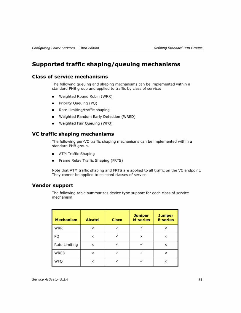
Configuring Policy Services – Third Edition Defining Standard PHB Groups
Supported traffic shaping/queuing mechanisms
Class of service mechanismsThe following queuing and shaping mechanisms can be implemented within a standard PHB group and applied to traffic by class of service:
Weighted Round Robin (WRR)
Priority Queuing (PQ)
Rate Limiting/traffic shaping
Weighted Random Early Detection (WRED)
Weighted Fair Queuing (WFQ)
VC traffic shaping mechanismsThe following per-VC traffic shaping mechanisms can be implemented within a standard PHB group.
ATM Traffic Shaping
Frame Relay Traffic Shaping (FRTS)
Note that ATM traffic shaping and FRTS are applied to all traffic on the VC endpoint. They cannot be applied to selected classes of service.
Vendor supportThe following table summarizes device type support for each class of service mechanism.
Mechanism Alcatel CiscoJuniper M-series
Juniper E-series
WRR × ×
PQ × × ×
Rate Limiting × ×
WRED × ×
WFQ × ×
Service Activator 5.2.4 91

Defining Standard PHB Groups Configuring Policy Services – Third Edition
*Only applies to a port in a layer 2 site
Class of service mechanism combinationsThe following CoS mechanism combinations are permitted in a standard PHB group:
ATM Traffic Shaping
× × ×
FRTS × × ×
If you apply FRTS to Frame Relay interfaces on distributed platforms, such as 75xx VIP-based devices, Service Activator configures Distributed Traffic Shaping (DTS) rather than via FRTS. Alternatively, you can apply FRTS to Frame Relay interfaces on distributed platforms using an MQC PHB group. For more information, see Defining MQC PHB Groups on page 111.
Mechanism Alcatel CiscoJuniper M-series
Juniper E-series
WR
R
WFQ
PQ
WR
ED
Rate
Lim
iting
ATM
TS
FR
TS
WRRx x x x x
WFQx x x x x
PQx x x x
WREDx x x x x
Rate Limitingx x x x
ATM TSx
FRTSx x
92 Service Activator 5.2.4
Configuring Policy Services – Third Edition Defining Standard PHB Groups
Note: – Can be selected together
x – Cannot be selected together
WRR and Priority Queuing are mutually exclusive, but on some devices you can implement rate limiting in conjunction with a queuing mechanism.
On Cisco devices, you can implement Low Latency Queuing (LLQ) on a Frame Relay interface by selecting Priority Queuing for class-based WFQ in combination with FRTS or you can use an MQC PHB group.
You can also apply Priority Queuing or WRR in combination with FRTS.
Before setting up a standard PHB groupThis section outlines the points you need to consider before setting up a standard PHB group.
Selecting the queuing or traffic shaping mechanismsThe decision as to which queuing or traffic shaping mechanism to use depends on the policy you want to implement and the capabilities of the router. Since the available techniques are often specific to the device type, operating system and interface, we advise that you consult the relevant vendor’s documentation for your specific device.
Service Activator reports the capabilities of each interface and you should ensure a mechanism is supported before attempting to configure it. For information on checking an interface’s capabilities, see the Network Discovery and Basic Setup guide. For more information about supported capabilities, consult the router documentation.
You need to set up a standard PHB group for each different queuing mechanism you want to implement. If all the routers to be managed are the same – the same model from the same vendor running the same operating system – you need only set up one. If you have different types and models you may need to set up several.
Deciding where to apply the standard PHB groupsA standard PHB group defines a queuing or shaping mechanism that may be used at various points in the network. For example, a PHB group might be used to manage the traffic going into the core network or to maintain the prioritization set up at the network edge throughout the core network.
PHB groups are implemented on the inbound and/or outbound interfaces of the routers to which they are applied. However, they are created as templates within a domain and can be applied to various points throughout the network.
Service Activator 5.2.4 93

Defining Standard PHB Groups Configuring Policy Services – Third Edition
A system of inheritance applies – for more information, see Policy inheritance on page 8.
If a PHB group applies to all devices and interfaces that share the same role it can be applied to the root level network and will automatically apply to all relevant interfaces throughout the network.
Using roles in PHB groupsEvery PHB group must have a device and interface role associated with it. The roles you associate with a PHB group specify to which policy targets the queuing mechanism will apply. For information on using roles in policy elements, see Using roles in policy elements on page 6.
Depending on the roles that you assign to policy targets, it is possible to apply policy only at very specific points in the network. For example, you can apply a role to a sub-interface independent of its parent interface. By associating a PHB group with the sub-interface role you can apply policy only at the sub-interface.
Importing policy files
Service Activator provides sample PHB groups and policy rules in policy files located in the SamplePolicy directory. For information on loading these policy files, see Importing policy files on page 26.
Service Activator applies only one concrete PHB group to an interface. If you apply a PHB group to the root level network, a concrete PHB group will not be created on an interface tagged with the appropriate role if a concrete PHB group already exists on that interface. However, a concrete standard PHB group that configures FRTS or ATM traffic shaping can be installed on an interface that has a concrete MQC PHB group that is configured with other QoS mechanisms.
When you create a PHB group there are no policy roles associated with it by default. You must associate both a device and an interface role for the PHB group’s configuration to be applied at the appropriate points in the network. If either the device or interface role are not specified, no configuration will be applied.
94 Service Activator 5.2.4
Configuring Policy Services – Third Edition Defining Standard PHB Groups
Setting up a standard PHB groupWhen setting up a standard PHB group you must specify:
The classes of service and/or VCs that are to be controlled by the PHB group.
The roles that define the policy target of the PHB group
The queuing mechanism to be used, and any specific parameters that need to be set. This will depend on the mechanisms available on the devices to which the PHB group will be applied.
Note: For complete dialog box and property page descriptions, refer to the Online Help.
To set up a standard PHB group
1. Do one of the following:
— On the Policy tab, select the PHB Groups folder
— Select a network component, customer, site or VPN
2. Right-click on the selected object and select Add PHB Group from the pop-up menu.
The PHB Group dialog box opens.
Service Activator 5.2.4 95

Defining Standard PHB Groups Configuring Policy Services – Third Edition
3. Enter values including Name, Configured Name, and Direction.
4. If a Virtual Circuit-based mechanism is to be applied, select ATM or FRTS.
Note that these techniques are applied to all traffic on the VC, not per class of service. You can configure FRTS in conjunction with WRR, Priority Queuing, CB-WFQ or WRED for finer control of traffic prioritization and queuing.
5. If a CoS-based mechanism is to be applied, specify the classes of service that are to be controlled by this PHB group. Select one or more classes of service in the excluded list (on the left), and click on the Add button to move them to the included list (on the right). The Default Class of Service is always included.
6. Select the CoS queuing mechanism(s) that the PHB group will apply.
WRR and PQ are mutually exclusive, but on some devices you can implement rate limiting in conjunction with a queuing mechanism.
CB-WFQ and WRED can be applied in combination.
Click Apply to apply the changes before setting specific details of the selected CoS mechanisms.
96 Service Activator 5.2.4

Configuring Policy Services – Third Edition Setting up Weighted Round Robin
7. Select the Role page and select the device and interface roles to which the PHB group applies.
You must specify both a device and an interface role. The system-defined Any Role can be used to apply the PHB group to any device or interface tagged with a role. For information on using roles in PHB groups, see Using roles in PHB groups on page 94.
8. Select the appropriate page(s), depending on the mechanism(s) selected and set the appropriate parameters. For details of configuring each mechanism, see the appropriate description:
WRR – Setting up Weighted Round Robin on page 97
PQ – Setting up Priority Queuing on page 98
Rate Limiting/Traffic Shaping – Setting up Rate Limiting on page 99
WFQ – Setting up Weighted Fair Queuing on page 102
WRED – Setting up Weighted Random Early Detection on page 100
FRTS – Setting up Frame Relay Traffic Shaping on page 106
ATM Traffic Shaping – Setting up ATM traffic shaping on page 105
9. Click OK to close the dialog box and save the PHB group.
Setting up Weighted Round Robin
Weighted Round Robin (WRR) is a mechanism for allocating bandwidth to queues so that higher priority applications have more bandwidth than lower priority applications when the network is congested. Custom Queuing in Cisco devices is an implementation of WRR.
WRR is implemented by the Alcatel, Cisco, Juniper M-series device drivers (Custom Queuing on Cisco routers). For more details, see the Cisco Device Driver Guide and the Juniper Device Driver Technical Note.
Note: For complete dialog box and property page descriptions, refer to the Online Help.
To set up WRR
1. Select the WRR property page on the PHB Group dialog box.
The PHB group is not implemented until it is propagated to the network by committing the transaction. For more information, see the Network Discovery and Basic Setup guide.
Service Activator 5.2.4 97

Setting up Weighted Round Robin Configuring Policy Services – Third Edition
2. Choose the Class of Service and set Weight and Packet limit values.
3. Click Set before changing another value. The specified weight is converted to a bandwidth percentage.
4. Repeat steps 2 to 3 for each class of service to be set up.
Setting up Priority QueuingPriority Queuing specifies that each packet is to be placed in one of a number of queues according to its priority. Packets on the highest-priority queue are transmitted first; when that queue is empty, packets on the next-highest queue are transmitted, and so on.
Priority Queuing is implemented by the Cisco device drivers. For more details, see the Cisco Device Driver Guide.
Note: For complete dialog box and property page descriptions, refer to the Online Help.
To set up Priority Queuing
1. Select the Priority Queuing page on the PHB Group dialog box.
98 Service Activator 5.2.4

Configuring Policy Services – Third Edition Setting up Weighted Round Robin
2. Selecting each CoS in turn, specify the Priority that will be applied (High, Medium, Normal or Low).
3. Click Set before changing another value.
4. Repeat steps 2 to 3 for each class of service to be set up.
Setting up Rate LimitingRate limiting, or traffic shaping, constrains specific outbound traffic to a particular bandwidth. It is commonly used to control access to the core network. It can be used to regulate the flow of traffic in order to avoid the congestion that can occur when transmitted traffic exceeds the access speed of the remote interface.
Rate Limiting is implemented by the Cisco device driver, by means of Generic Traffic Shaping (GTS), and by the Juniper M-series device driver. For more details, see the Cisco Device Driver Guide and the Juniper Device Driver Technical Note.
Note: For complete dialog box and property page descriptions, refer to the Online Help.
To set up Rate Limiting
1. Select the Rate Limiting page on the PHB Group dialog box.
2. Choose the Class of Service and set the Average rate, Burst rate, and Burst interval.
Service Activator 5.2.4 99
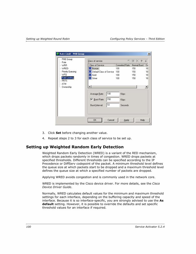
Setting up Weighted Round Robin Configuring Policy Services – Third Edition
3. Click Set before changing another value.
4. Repeat steps 2 to 3 for each class of service to be set up.
Setting up Weighted Random Early DetectionWeighted Random Early Detection (WRED) is a variant of the RED mechanism, which drops packets randomly in times of congestion. WRED drops packets at specified thresholds. Different thresholds can be specified according to the IP Precedence or DiffServ codepoint of the packet. A minimum threshold level defines the queue size at which packets start to be dropped and a maximum threshold level defines the queue size at which a specified number of packets are dropped.
Applying WRED avoids congestion and is commonly used in the network core.
WRED is implemented by the Cisco device driver. For more details, see the Cisco Device Driver Guide.
Normally, WRED calculates default values for the minimum and maximum threshold settings for each interface, depending on the buffering capacity and speed of the interface. Because it is so interface-specific, you are strongly advised to use the As default setting. However, it is possible to override the defaults and set specific threshold values for an interface if required.
100 Service Activator 5.2.4

Configuring Policy Services – Third Edition Setting up Weighted Round Robin
An MQC PHB group configured with congestion avoidance can use the WRED settings configured in a standard PHB group. The standard PHB group must only have WRED configured, can have any CoS associated with it that is not linked to a classification and must be linked to at least one packet marking. For more information, see Setting up Congestion Avoidance on page 136.
Note: For complete dialog box and property page descriptions, refer to the Online Help.
To set up WRED with default values
1. Select the WRED property page on the PHB Group dialog box.
2. Ensure the As default checkbox is selected.
3. Click Apply or OK.
To set up WRED with specific values for an interface
1. Select the WRED property page on the PHB Group dialog box.
2. Clear the As default checkbox.
3. Select Explicit Congestion Notification if required.
If the maximum threshold and minimum threshold are set to the same value and a specific hardware/IOS combination does not allow them to be equal, then the commit fails and the device is set to Intervention Required.
Service Activator 5.2.4 101

Setting up Weighted Round Robin Configuring Policy Services – Third Edition
4. Choose the Class of Service for which you want to set specific parameters.
5. Specify the Min threshold, Max threshold, and Drop probability.
6. If necessary, amend the default Weight Factor – an exponent weight factor used to calculate the average queue size. The range is 1 to 16, the default is 9.
7. Click Set before changing another value.
8. Repeat steps 3 to 6 for each class of service to be set up.
You can configure WRED in conjunction with Class-based WFQ to define the drop strategy. See Setting up Weighted Fair Queuing on page 102.
Setting up Weighted Fair QueuingWeighted Fair Queuing (WFQ) is a queuing algorithm used for congestion management.
There are two types of WFQ: flow-based and class-based.
102 Service Activator 5.2.4

Configuring Policy Services – Third Edition Setting up Weighted Round Robin
Flow-based is used by default on all serial interfaces less than 2 Mbits/s on Cisco routers. A flow is identified as all packets with the same source IP address, destination IP address and source or destination TCP or UDP port. WFQ allocates an equal share of the available bandwidth to each flow.
Class-based WFQ (CB-WFQ) is only supported on a restricted set of Cisco routers. It allows you to allocate a particular bandwidth to a particular class of service. Each class is allocated to a particular queue according to its bandwidth. A traffic class allocated a higher bandwidth has a higher priority than a traffic class allocated less bandwidth.
On Cisco routers, for interfaces that support WFQ you can either specify that flow-based WFQ is applied, or select CB-WFQ and set specific parameters for each class of service.
CB-WFQ can also be implemented on Cisco devices using an MQC PHB group. For more information, see Setting up Class-Based Weighted Fair Queuing on page 124.
On Cisco devices, by default, flow-based queuing is applied and no parameters can be set. Since there may be very large numbers of individual flows, and one queue per flow, this is process-intensive, and is not recommended for fast interfaces.
For details of WFQ implementation on Cisco devices, see the Cisco Device Driver Guide.
Note: For complete dialog box and property page descriptions, refer to the Online Help.
To set up flow-based WFQ
1. Select the WFQ property page on the PHB Group dialog box.
2. Ensure the Class Based checkbox is cleared.
3. Click OK. Flow-based WFQ is configured on the appropriate interfaces using default parameters.
To set up CB-WFQ
1. Select the WFQ property page on the PHB Group dialog box.
2. Select the Class Based checkbox.
Service Activator 5.2.4 103
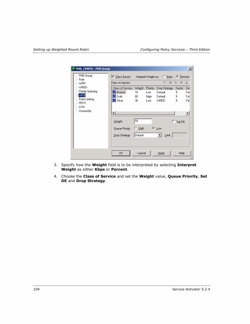
Setting up Weighted Round Robin Configuring Policy Services – Third Edition
3. Specify how the Weight field is to be interpreted by selecting Interpret Weight as either Kbps or Percent.
4. Choose the Class of Service and set the Weight value, Queue Priority, Set DE and Drop Strategy.
104 Service Activator 5.2.4

Configuring Policy Services – Third Edition Setting up Weighted Round Robin
For details of configuring WRED, see Setting up Weighted Random Early Detection on page 100.
5. Click the Set button before changing another value
6. Repeat steps 3 to 5 for each class of service to be set up.
Setting up ATM traffic shapingTraffic shaping specifies a queuing mechanism to limit surges that can congest a network. Data is buffered and then sent into the network in regulated amounts to ensure that the traffic will fit within the promised traffic envelope for the particular connection.
ATM traffic shaping is implemented by the Cisco device driver. For more information, see the Cisco Device Driver Guide.
Note: For complete dialog box and property page descriptions, refer to the Online Help.
For information on monitoring the class maps that are configured for a CB WFQ PHB group, see the Network and SLA Monitoring guide.
Service Activator 5.2.4 105

Setting up Weighted Round Robin Configuring Policy Services – Third Edition
To set up ATM Traffic Shaping
1. Select the ATM property page on the PHB Group dialog box.
2. In the filed VC class name select Generated to use a system generated VC class name. To manually specify a name, type the name in the field. The maximum length of the name is 126 characters.
3. Select the Service Category.
4. Set the appropriate parameters including PCR, SCR MBS and MCR.
5. Specify appropriate values in Hold queue depth and Transmit ring buffer limit.
Setting up Frame Relay Traffic ShapingFrame Relay Traffic Shaping (FRTS) delays excess traffic using a queuing mechanism to hold packets and shape the flow when the data rate of the source is higher than expected. FRTS is sometimes used to eliminate bottlenecks in Frame
106 Service Activator 5.2.4

Configuring Policy Services – Third Edition Setting up Weighted Round Robin
Relay networks that have high-speed connections at the central site and low-speed connections at branch sites. A rate enforcement is configured to limit the rate at which data is sent on the VC at the central site.
FRTS is applied at VC level and can be combined with PQ, WRR, CB-WFQ or WRED applied at the VC or sub-interface. This allows for finer control over traffic prioritization and queuing.
You can configure FRTS to use information contained in the BECN (Backward Explicit Congestion Notification) and FECN (Forward Explicit Congestion Notification)-tagged frames received from the network. These features throttle traffic dynamically when congestion occurs.
The FRTS PHB group also allows you to apply FRF.12 fragmentation to traffic, either in conjunction with traffic shaping or independently. FRF.12 is a Frame Relay standard that allows long data frames to be fragmented into smaller pieces and interleaved with real-time frames. This means that real-time voice and non real-time data frames can be carried together on lower speed networks without causing excessive delay to the real-time traffic.
FRTS is implemented by the Cisco device driver. For more details, see the Cisco Device Driver Guide.
You can implement LLQ on a Frame Relay interface by selecting FRTS in combination with CB-WFQ. For information on support for LLQ by Cisco devices, see the Cisco Device Driver Guide.
Note: For complete dialog box and property page descriptions, refer to the Online Help.
To set up FRTS
1. Select the FRTS property page on the PHB Group dialog box.
FRTS can be applied in combination with PQ, WRR, CB-WFQ or WRED, but you cannot use FRF.12 in combination with WRR or Priority Queuing.
Service Activator 5.2.4 107

Setting up Weighted Round Robin Configuring Policy Services – Third Edition
2. To configure FRF.12, select the FRF.12 checkbox and set the required Fragment size, in the range 16-1600 bytes.
3. To configure traffic shaping, select the Shaping checkbox and set the parameters including CIR, Min CIR, Bc, and Be. You can configure Inbound and Outbound parameters independently, for vendor specific devices.
4. Select the BECN Adapt checkbox if you want to monitor for Frame Relay frames that have the BECN (Backward Explicit Congestion Notification) bit set.
5. Select the FECN Adapt checkbox if you want to monitor for Frame Relay frames that have the FECN (Forward Explicit Congestion Notification) bit set.
6. In the Hold queue depth, specify the maximum number of packets that can be stored in the traffic-shaping queue for a Frame Relay PVC. Select Device default to specify the default value for that particular device. The range is 1 to 2048 packets.
108 Service Activator 5.2.4

Configuring Policy Services – Third Edition Setting up Weighted Round Robin
Distributed Traffic Shaping
If you apply FRTS to Frame Relay interfaces on distributed platforms, such as 75xx VIP-based devices, Service Activator configures Distributed Traffic Shaping (DTS) rather than via FRTS. Like other traffic shaping mechanisms, DTS buffers excess traffic and regulates the rate at which packets are sent into the network, setting a Committed Information Rate (CIR) a Committed Burst (Bc) and an Excess Burst rate (Be).
Although the same parameters are configured for DTS, note that the permitted parameter ranges are different from those for FRTS:
Parameter Range
CIR 1-45000000
Min CIR 1000-45000000
Bc 300-16000000
Be 0-16000000
Service Activator 5.2.4 109

Setting up Weighted Round Robin Configuring Policy Services – Third Edition
110 Service Activator 5.2.4

Configuring Policy Services – Third Edition Defining MQC PHB Groups
Chapter 5
Defining MQC PHB Groups
This chapter describes how to define Modular QoS CLI policies for Cisco devices using MQC PHB groups. The chapter:
Provides an overview of MQC PHB groups and the traffic management mechanisms that can be implemented using Service Activator
Highlights points you should consider before setting up MQC PHB groups
Describes how to set up and manage MQC PHB groups
Explains how to implement MQC PHB groups and understand the information that Service Activator displays for implemented MQC PHB groups
For information on defining standard PHB groups, see Chapter 4. For details on implementing and managing PHB groups, see Chapter 6.
Service Activator 5.2.4 111

Defining MQC PHB Groups Configuring Policy Services – Third Edition
IntroductionMQC (Modular QoS CLI) PHB groups allow you to implement Cisco’s simplified configuration of policy mechanisms and actions for traffic queuing, shaping, policing, congestion avoidance and re-marking on the interfaces of Cisco routers and switches. You can specify several different QoS mechanisms for different classes of service associated with the same MQC PHB group.
An MQC PHB group defines the QoS policy that may be used at various points in the network. For example, an MQC PHB group might be used to manage the traffic going into the core network or to maintain the prioritization set up at the network edge throughout the core network.
An MQC PHB group may be applied to one or more classes of service that are based on a classification or classification group. The classification may be defined by factors such as source and/or destination IP address or account and traffic type. A number of classes of service may be linked to an MQC PHB group and one or more different mechanisms applied to each one.
CoS:Gold
Classification:Gold
MQC PHB GroupShape+Mark+Queue
CoS:Silver
CoS:Bronze
Classification:Silver
Classification:Bronze
CB-WFQShapingMarking
CB-WFQShapingMarking
CB-WFQShapingMarking
112 Service Activator 5.2.4
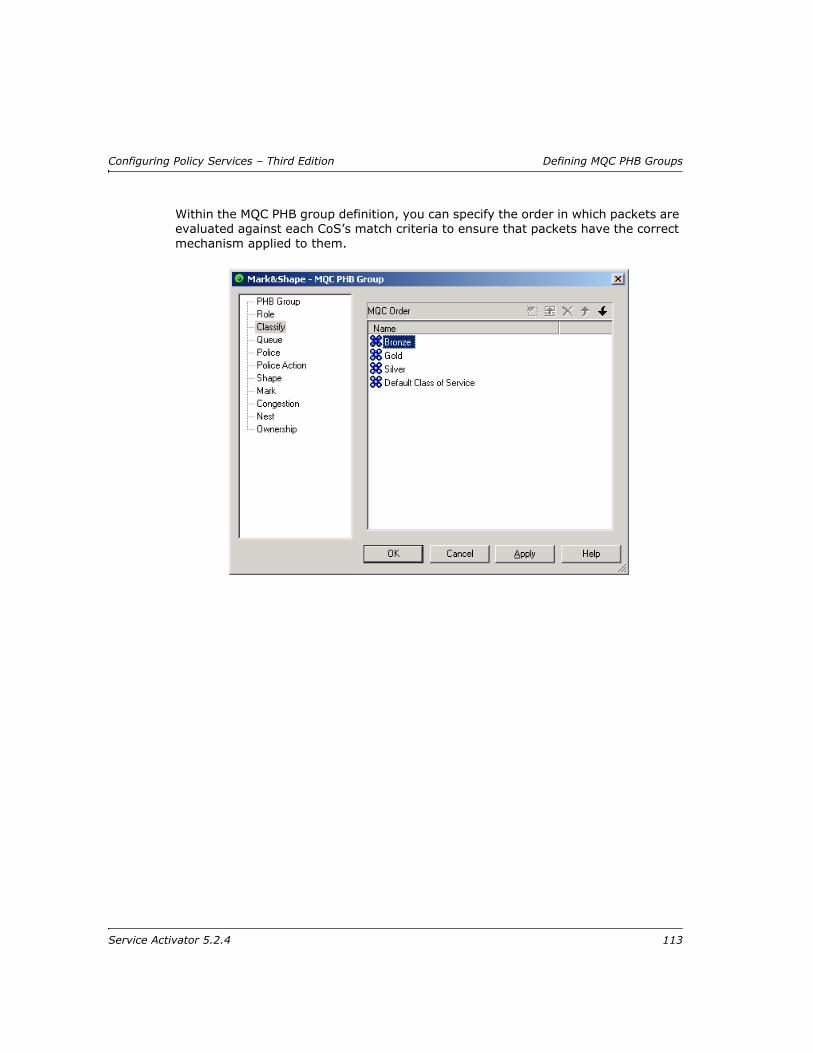
Configuring Policy Services – Third Edition Defining MQC PHB Groups
Within the MQC PHB group definition, you can specify the order in which packets are evaluated against each CoS’s match criteria to ensure that packets have the correct mechanism applied to them.
Service Activator 5.2.4 113

Defining MQC PHB Groups Configuring Policy Services – Third Edition
You can also nest an MQC PHB group within another MQC PHB group. This enables you to apply a policy to a broad range of traffic (defined by the parent MQC PHB group) and another to a subset of that range (defined by the child MQC PHB group).
Parent MQC group ‘Shape’ shapes all traffic on an interface, while child MQC PHB group ‘Queue’ queues Gold, Silver and Bronze traffic
114 Service Activator 5.2.4

Configuring Policy Services – Third Edition Defining MQC PHB Groups
An MQC PHB group is configured as a policy map and implemented at an interface as a service policy.
An MQC PHB group can be applied to a network component such as an interface or a VC endpoint, a customer, site or VPN.
Supported traffic management mechanismsThe following traffic management mechanisms can be implemented within an MQC PHB group and applied to traffic by class of service:
Low Latency Queuing (LLQ) – assigns a traffic class to a strict priority queue with a guaranteed maximum bandwidth during congestion
Class-based Weighted Fair Queuing (CB-WFQ) – assigns a traffic class to a queue with a priority based on a guaranteed minimum bandwidth during congestion
Class-based Policing – specifies and enforces conditions that define the maximum inbound and outbound bandwidth of a traffic class, packets that exceed the conditions can be dropped or re-marked
Class-based Shaping – specifies and constrains the maximum outbound bandwidth of a traffic class, outbound packets that exceed the conditions are delayed
Class-based Marking – marks packets to allocate a priority status or class
Congestion avoidance (Queue limit and/or WRED) – defines how packets are discarded during congestion
Service Activator’s ability to install an MQC PHB group on a network object is dependent on an interface’s capabilities. For example, an MQC PHB group that specifies single rate policing can only be installed on an interface whose capabilities show ‘SR Police’ support. For information on checking interface capabilities, see the Network Discovery and Basic Setup guide.
In many instances, MQC PHB groups can be configured on the same interface as policy rules. Note, however, that if a classification rule is configured on an interface using policy maps, you cannot configure an MQC PHB group on the same interface. For information on which mechanisms are used to configure classification rules, see the Cisco Device Driver Guide.
Service Activator 5.2.4 115
Defining MQC PHB Groups Configuring Policy Services – Third Edition
Before setting up an MQC PHB groupThis section outlines the points you need to consider before setting up an MQC PHB group.
Deciding which QoS actions to selectThe decision as to which QoS action to use depends on the QoS policy you want to implement and the capabilities of the router. The available techniques are often specific to the device type, operating system and interface. You may find that some some QoS mechanisms can only be implemented on some devices using standard PHB groups. We recommend you consult Cisco’s documentation for your specific device.
Service Activator reports the capabilities of each interface and you should ensure that a QoS action is supported before attempting to configure it. For information on checking an interface’s capabilities, see the Network Discovery and Basic Setup guide. For more information about supported capabilities, consult the router documentation.
Defining Classes of ServiceBefore creating an MQC PHB group, you need to ensure you have specified the classification parameters for identifying traffic by setting up classes of service. MQC PHB groups operate on one or more classes of service defined by a classification or classification group. For information on defining a classification or classification group, see Setting up a classification on page 46. For information on defining traffic types, see Setting up traffic types on page 40.
Check capabilitiesBefore setting up MQC PHB groups, you need to know the capabilities of the policy targets to which you intend to apply policy. Check the Capabilities property page on relevant interfaces if necessary. See the Network Discovery and Basic Setup guide.
Note that you can associate a CoS defined by a classification or classification group and/or a packet marking with an MQC PHB group. However, the MQC PHB group only operates on the traffic defined by a classification or classification group – packet markings are ignored. If you wish to define a traffic class that is characterized by a packet marking, you must create a packet marking traffic type and associate it with a classification.
116 Service Activator 5.2.4

Configuring Policy Services – Third Edition Defining MQC PHB Groups
Deciding where to apply MQC PHB groupsMQC PHB groups are implemented on the inbound and/or outbound interfaces of the routers to which they are applied. They are created as templates either within a domain or at device level. If created at domain level, they are applied to various points throughout the network through inheritance so that they are applied to interfaces tagged with the appropriate role. However, an MQC PHB created at device level will apply only to that device’s interfaces.
A system of inheritance applies – for more information, see Policy inheritance on page 8.
If an MQC PHB group applies to all devices and interfaces that share the same role it can be applied to the root level network and will automatically apply to all relevant interfaces throughout the network.
Using roles in MQC PHB groupsEvery MQC PHB group must have a device and interface role associated with it. The roles you associate with an MQC PHB group specify to which policy targets the queuing mechanism will apply.
Depending on the roles that you assign to policy targets, it is possible to apply policy only at very specific points in the network. For example, you can apply a role to a sub-interface independent of its parent interface. By associating an MQC PHB group with the sub-interface role, you can apply a QoS policy only at the sub-interface.
For information on using roles, see Using roles in policy elements on page 6.
Service Activator applies only one concrete MQC PHB group to an interface. If you apply an MQC PHB group to the root level network, a concrete MQC PHB group is only created on an interface tagged with the appropriate role if there is no concrete MQC PHB group already installed on that interface. However, a concrete standard PHB group that configures FRTS or ATM traffic shaping can be installed on an interface that has a concrete MQC PHB group that is configured with other QoS mechanisms.
When you create an MQC PHB group there are no policy roles associated with it by default. You must associate both a device and an interface role for the MQC PHB group’s configuration to be applied at the appropriate points in the network. If either the device or interface role are not specified, no configuration will be applied.
Service Activator 5.2.4 117

Defining MQC PHB Groups Configuring Policy Services – Third Edition
Setting up an MQC PHB group
To set up an MQC PHB group
1. Do one of the following:
On the Policy tab, select the MQC PHB Groups folder
Select a network component, customer, site or VPN
2. Right-click on the folder and select Add MQC PHB Group from the pop-up menu.
The MQC PHB Group dialog box opens.
Enter values including Name, Configured Name, Description, and Direction.
3. Select a CoS so that it is highlighted and its checkbox is checked.
4. Select one or several QoS actions that you want to associate with the selected CoS including LLQ, CB-WFQ, SR Police, TR Police, Shape, Mark, Congestion, Nest, RTP Compression
118 Service Activator 5.2.4

Configuring Policy Services – Third Edition Defining MQC PHB Groups
Note: See MQC PHB QoS Action Combinations in the Online Help for a table indicating which combinations of QoS actions are allowed.
5. Repeat steps 4 to 6 for each CoS that you want to use.
6. Click the Apply button to apply the changes.
To remove all QoS actions associated with a CoS, click on the CoS to clear its checkbox.
7. Select the Role property page and select the device and interface roles to which the MQC PHB group applies.
You must specify both a device and an interface role. The system-defined Any Role can be used to apply the MQC PHB group to any device or interface tagged with a role. For information on using roles in MQC PHB groups, see Using roles in MQC PHB groups on page 117.
8. Select the appropriate page(s), depending on the QoS actions selected, and set the appropriate parameters. For details of configuring each QoS action, see the appropriate description:
Matching – Specifying evaluation order on page 119
LLQ – Setting up Low Latency Queuing on page 122
CB-WFQ – Setting up Class-Based Weighted Fair Queuing on page 124
Policing – Setting up Class-Based Policing on page 125
Policing action – Setting up a policing action on page 129
Shaping – Setting up Class-Based Shaping on page 131
Marking – Setting up Class-Based Marking on page 135
Congestion avoidance – Setting up Congestion Avoidance on page 136
Nesting – Nesting MQC PHB groups on page 138
RTP compression – RTP Header Compression on page 142
9. Click OK to close the dialog box, and save the MQC PHB group.
Specifying evaluation orderYou specify the criteria for assessing whether a packet belongs to a CoS by defining a classification or classification group and linking it to a CoS. For information, see
The MQC PHB group is not implemented until it is propagated to the network by committing the transaction. For more information, see the Network Discovery and Basic Setup guide.
Service Activator 5.2.4 119

Defining MQC PHB Groups Configuring Policy Services – Third Edition
Using classifications with MQC PHB groups on page 47. By associating a CoS with an MQC PHB group, you specify the treatment to apply to that CoS.
The classes of service that have been associated with an MQC PHB group are listed on the MQC PHB group’s Classify property page.
The position of a CoS in the list can affect which QoS actions are applied to a packet. For example, Bronze and Gold classes of service may include the same destination address in their match criteria but have different QoS actions applied to them. They are listed in the order shown above. If both CoS’s match criteria is Match Any, a packet with the relevant destination address will be matched against the Bronze CoS and no further evaluations made. The packet therefore only has the QoS actions applied to it that have been defined for the Bronze CoS.
You can change the order in which a packet is evaluated against each CoS’s match criteria on the Classify page.
To specify match order
1. Select the Classify property page in the MQC PHB Group dialog box.
The match criteria for a CoS is defined by the classification or classification group that is linked to the CoS. For information on defining a classification or classification group, see page 52 and page 52.
120 Service Activator 5.2.4

Configuring Policy Services – Third Edition Defining MQC PHB Groups
All classes of service that you selected on the PHB Group page are listed in the MQC Order list.
2. If required, change the position of a CoS in the MQC Order list by selecting a
CoS and clicking the up or down arrows to move it up or down the list.
3. Save your settings by clicking Apply.
Re-ordering classes within Service Activator policies sends the correct configuration to the router, but some Cisco IOSs do not show the correct order on subsequent 'show run' commands. The router does not return any errors. There is no indication that the configuration has not been accepted by the router.
For problematic IOSs, the best work-around is to unlink the entire policy map, re-order the classes and then re-link the policy map. This will ensure that the correct ordering is applied to the router.
The following IOSs have been tested:
IOS Version Class re-order successful on router
12.3(3) Yes
12.2(19c) No
12.2(15)T10 Yes
12.2(12i) No
Service Activator 5.2.4 121

Defining MQC PHB Groups Configuring Policy Services – Third Edition
Setting up Low Latency QueuingYou use Low Latency Queuing (LLQ) to assign a strict priority to a CoS to allow delay-sensitive traffic to be given priority over less delay-sensitive traffic during congestion.
The operation of LLQ is identical to Class-Based Weighted Fair Queuing (CB-WFQ) except that LLQ has a strict priority queue.
You allocate a guaranteed bandwidth, that is a proportion of the output interface bandwidth, to one or more classes of service. When congestion occurs, each traffic flow is placed in its own queue. If there is only one flow of a particular CoS, it will be allocated all of the user-specified bandwidth for that CoS. If there are several flows of the same CoS, each flow queue is allocated an equal proportion of the user-specified bandwidth for that CoS. For example, if a CoS is allocated 60% of the output interface bandwidth, and there are three flows of the same CoS, each flow queue is allocated 20% of the output interface bandwidth.
During congestion, each queue is serviced in turn by a scheduling mechanism that forwards a number of bits from each packet in proportion to the queue’s allocated bandwidth. For example, if there are two CoS queues allocated bandwidth of 40% and 20%, each time a queue is serviced, twice as many bits are taken from a packet in the CoS queue allocated 40% bandwidth than bits taken from a packet in the CoS queue allocated 20% bandwidth.
If a CoS is not using its allocated bandwidth, the unused bandwidth is shared by the other classes of service.
During congestion, packets belonging to a CoS that is assigned LLQ are always allowed to be transmitted before packets of a CoS that is assigned CB-WFQ. However, any incoming packets of a traffic class assigned LLQ that exceed the allocated bandwidth will be dropped.
Note: For complete dialog box and property page descriptions, refer to the Online Help.
To set up LLQ
1. Select the Queue property page in the MQC PHB Group dialog box.
The classes of service that you selected with LLQ on the PHB Group page appear in the QoS Queue area.
12.2(8)T No
12.3(11)T No
122 Service Activator 5.2.4

Configuring Policy Services – Third Edition Defining MQC PHB Groups
2. Select a CoS and set the following parameters.
3. Select or clear the check box Maximum reserved bandwidth to enable/or disable this capability. If enabled specify a new value if required. Cisco devices have a default maximum reserve bandwidth value of 75 percent that is designed to leave sufficient bandwidth for overhead traffic. You can alter this by entering a percentile value.
4. Select a bandwidth option from the Interpret LLQ Weight as combo box (Absolute Bandwidth, Percentage of Bandwidth, Percentage of Remaining, Default).
5. Specify the Queue Weight value.
If you are changing the settings of several classes of service in the MQC PHB
group, use the Modify button to apply the changes to each CoS.
6. Specify a value in LLQ burst in bytes. Select Device default to specify the default value for that particular device.
7. Specify the Fair-queue values to configure fair-queuing.
Service Activator 5.2.4 123

Defining MQC PHB Groups Configuring Policy Services – Third Edition
8. Select the next CoS in the list and repeat steps 3 to 6.
9. Save your settings by clicking Apply.
Setting up Class-Based Weighted Fair QueuingYou use Class-Based Weighted Fair Queuing to assign a priority to a CoS based on bandwidth.
You allocate a minimum bandwidth, that is a proportion of the output interface bandwidth, to one or more classes of service. When congestion occurs, each traffic flow is placed in its own queue. If there is only one flow of a particular CoS, it will be allocated all of the user-specified bandwidth for that CoS. If there are several flows of the same CoS, each flow queue is allocated an equal proportion of the user-specified bandwidth for that CoS. For example, if a CoS is allocated 60% of the output interface bandwidth, and there are three flows of the same CoS, each flow queue is allocated 20% of the output interface bandwidth.
During congestion, each queue is serviced in turn by a scheduling mechanism that forwards a number of bits from each packet in proportion to the queue’s allocated bandwidth. For example, if there are two CoS queues allocated bandwidth of 40% and 20%, each time a queue is serviced, twice as many bits are taken from a packet in the CoS queue allocated 40% bandwidth than bits taken from a packet in the CoS queue allocated 20% bandwidth.
If a CoS is not using its allocated bandwidth, the unused bandwidth is shared by the other classes of service.
The operation of CB-WFQ configured using MQC PHB and standard PHB groups is identical.
Note: For complete dialog box and property page descriptions, refer to the Online Help.
To set up CB-WFQ
1. Select the Queue property page in the MQC PHB Group dialog box.
The classes of service that you selected with CBWFQ on the PHB Group page appear in the QoS Queue area.
124 Service Activator 5.2.4
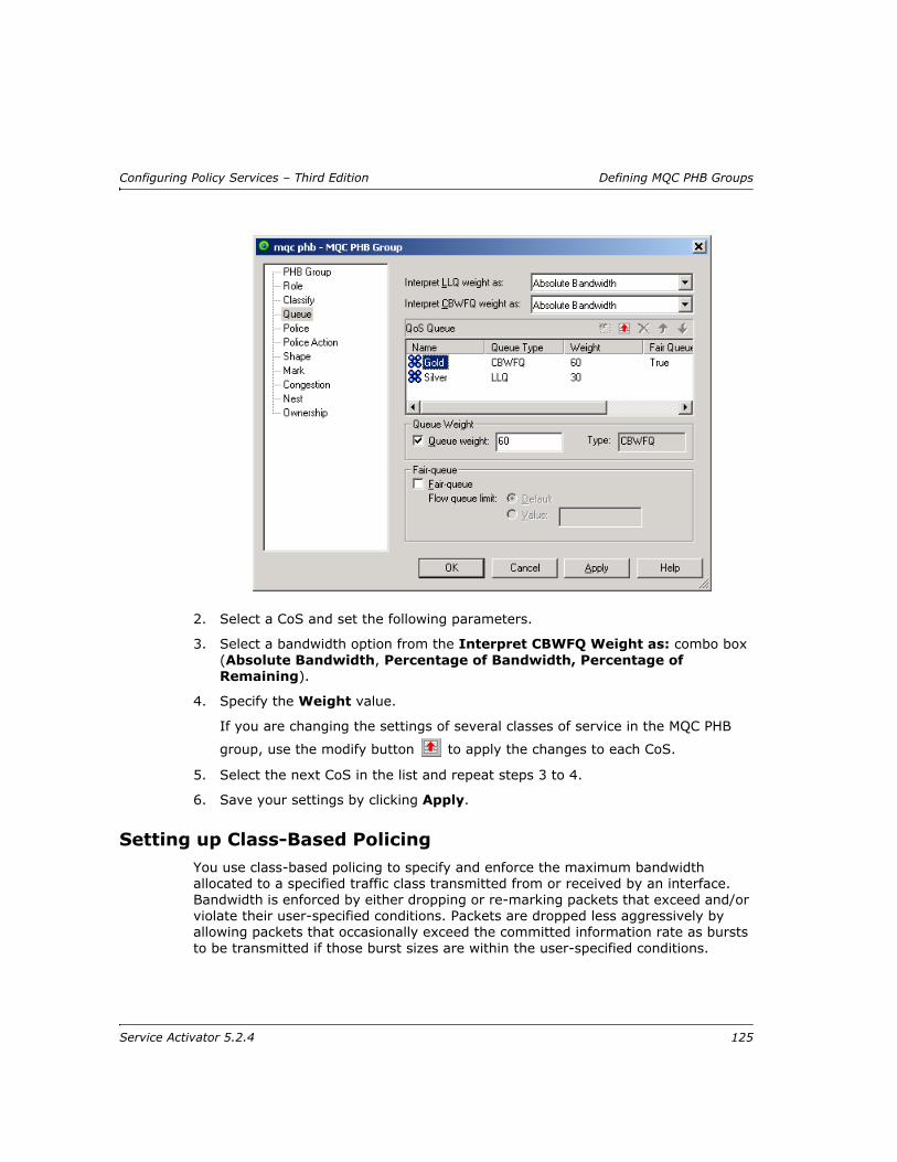
Configuring Policy Services – Third Edition Defining MQC PHB Groups
2. Select a CoS and set the following parameters.
3. Select a bandwidth option from the Interpret CBWFQ Weight as: combo box (Absolute Bandwidth, Percentage of Bandwidth, Percentage of Remaining).
4. Specify the Weight value.
If you are changing the settings of several classes of service in the MQC PHB
group, use the modify button to apply the changes to each CoS.
5. Select the next CoS in the list and repeat steps 3 to 4.
6. Save your settings by clicking Apply.
Setting up Class-Based PolicingYou use class-based policing to specify and enforce the maximum bandwidth allocated to a specified traffic class transmitted from or received by an interface. Bandwidth is enforced by either dropping or re-marking packets that exceed and/or violate their user-specified conditions. Packets are dropped less aggressively by allowing packets that occasionally exceed the committed information rate as bursts to be transmitted if those burst sizes are within the user-specified conditions.
Service Activator 5.2.4 125

Defining MQC PHB Groups Configuring Policy Services – Third Edition
You specify the maximum rate and burst size(s) that define the conditions a packet is required to conform to. These values represent the policing profile of the CoS and are specified on the Police page.
For single rate policing, a conform condition indicates that a packet’s Committed Information Rate (CIR) is within the specified CIR. An exceed condition indicates that a packet’s CIR is above the specified CIR. A violate condition indicates that a packet’s Committed Burst Size (CBS) and Excess Burst Size (EBS) are both above the specified CBS and EBS.
For two rate policing, a conform condition indicates that a packet’s CIR and peak information rate (PIR) is within the specified CIR and PIR. An exceed condition indicates that a packet’s PIR is within the specified PIR but is above the specified CIR. A violate condition indicates that a packet’s PIR is above the specified PIR.
You specify the actions performed on packets that conform, exceed or violate specified conditions on the Police Action page.
The following steps are required to configure class-based policing using an MQC PHB group:
1. Set up a policing profile for a CoS on the Police page of an MQC PHB Group dialog box.
2. Set up policing actions for conform, exceed and violate conditions on the Policing Action page of a PHB Policing Action dialog box.
3. Associate policing actions with a CoS on the Police Action page of the MQC PHB Group dialog box.
Note that policing actions can be set up before setting up policing profiles.
Note: For complete dialog box and property page descriptions, refer to the Online Help.
To set up single rate class-based policing
Single rate class-based policing measures bandwidth conformance of traffic based on its Committed Information Rate, Committed Burst Size and Excess Burst Size.
1. Select the Police property page in the MQC PHB Group dialog box.
The classes of service that you selected with SR Police on the PHB Group page appear in the QoS Policing area.
126 Service Activator 5.2.4
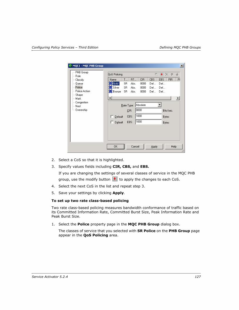
Configuring Policy Services – Third Edition Defining MQC PHB Groups
2. Select a CoS so that it is highlighted.
3. Specify values fields including CIR, CBS, and EBS.
If you are changing the settings of several classes of service in the MQC PHB
group, use the modify button to apply the changes to each CoS.
4. Select the next CoS in the list and repeat step 3.
5. Save your settings by clicking Apply.
To set up two rate class-based policing
Two rate class-based policing measures bandwidth conformance of traffic based on its Committed Information Rate, Committed Burst Size, Peak Information Rate and Peak Burst Size.
1. Select the Police property page in the MQC PHB Group dialog box.
The classes of service that you selected with SR Police on the PHB Group page appear in the QoS Policing area.
Service Activator 5.2.4 127
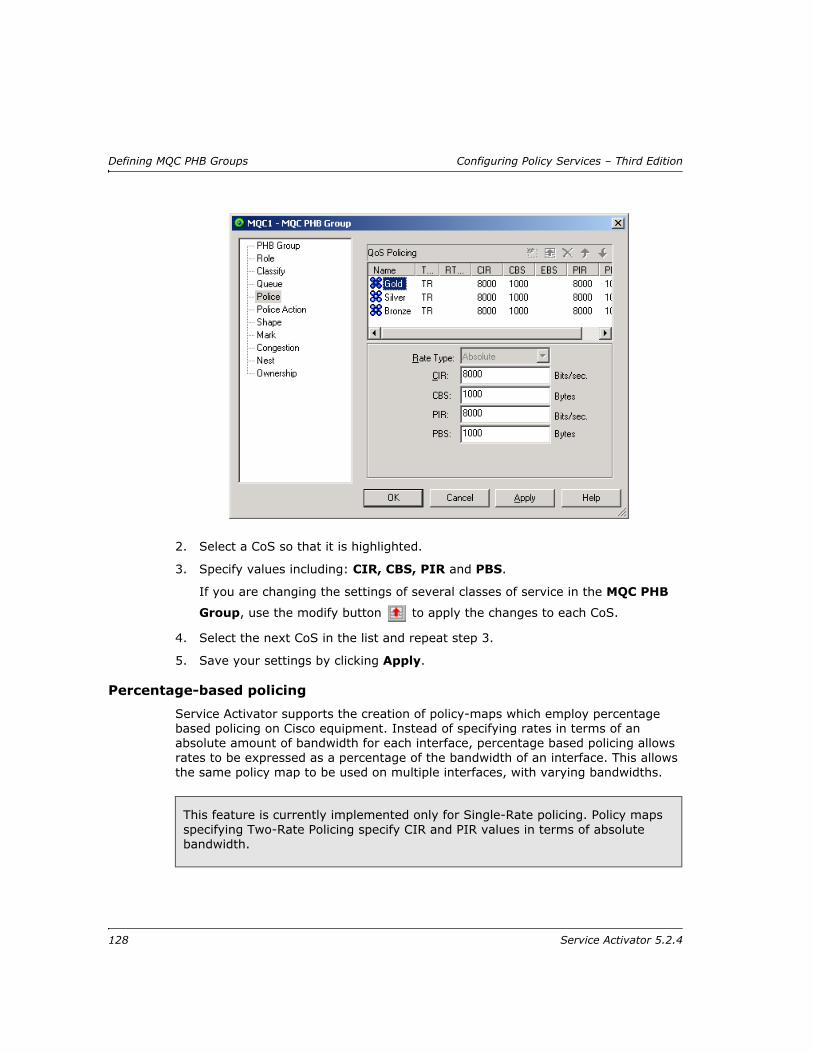
Defining MQC PHB Groups Configuring Policy Services – Third Edition
2. Select a CoS so that it is highlighted.
3. Specify values including: CIR, CBS, PIR and PBS.
If you are changing the settings of several classes of service in the MQC PHB
Group, use the modify button to apply the changes to each CoS.
4. Select the next CoS in the list and repeat step 3.
5. Save your settings by clicking Apply.
Percentage-based policing
Service Activator supports the creation of policy-maps which employ percentage based policing on Cisco equipment. Instead of specifying rates in terms of an absolute amount of bandwidth for each interface, percentage based policing allows rates to be expressed as a percentage of the bandwidth of an interface. This allows the same policy map to be used on multiple interfaces, with varying bandwidths.
This feature is currently implemented only for Single-Rate policing. Policy maps specifying Two-Rate Policing specify CIR and PIR values in terms of absolute bandwidth.
128 Service Activator 5.2.4

Configuring Policy Services – Third Edition Defining MQC PHB Groups
MQC percentage based policing is configured in Service Activator in the MQC PHB Group dialog box.
On the PHB Group page, select the MQC Action to apply percentage based policing to, and then select the SR Police (single rate police) checkbox for the MQC Action.
The percentage rates are then specified on the Police page. Select Percent in the Rate Type dropdown.
You can activate aggregate policing by selecting Aggregate Policer Name and specify the name if the aggregate policer in the text box.
Note: For complete dialog box and property page descriptions, refer to the Online Help.
Setting up a policing action
You can specify the treatment of packets that conform to, or exceed the rate value(s), or violate the burst sizes that are specified for a CoS on the Police page. You can specify a separate action for each of these three states. For example, you can specify packets that conform are transmitted, packets that exceed are re-marked and transmitted, and packets that violate are dropped. Re-marked packets determine how they are treated by QoS mechanisms set up on interfaces downstream. An action can implement several types of marking.
Service Activator 5.2.4 129

Defining MQC PHB Groups Configuring Policy Services – Third Edition
A policing action is defined by setting up a PHB Policing Action object which can then be specified as either the conform, exceed or violate action for a CoS on the Police Action page of the MQC PHB dialog box. You can either use default PHB policing actions or specify your own. A PHB Policing Action can be used by several MQC PHB groups.
Note: For complete dialog box and property page descriptions, refer to the Online Help.
To set up a PHB policing action
1. On the Policy tab, select the PHB Policing Action folder.
2. Right-click and select Add PHB Policing Action from the pop-up menu.
3. The PHB Policing Action dialog box opens.
4. Enter a Name for the PHB Policing Action.
5. Select either Drop or Transmit.
6. If you select Transmit, specify how you want packets to be marked by selecting an action including Set ATM CLP, Set FR DE, Set IP Marking, Set MPLS Exp. If you do not select a marking, the packet is transmitted unmarked.
7. Save your settings by clicking Apply.
Applying a policing action
Apply a PHB policing action by associating it with an MQC PHB group.
130 Service Activator 5.2.4
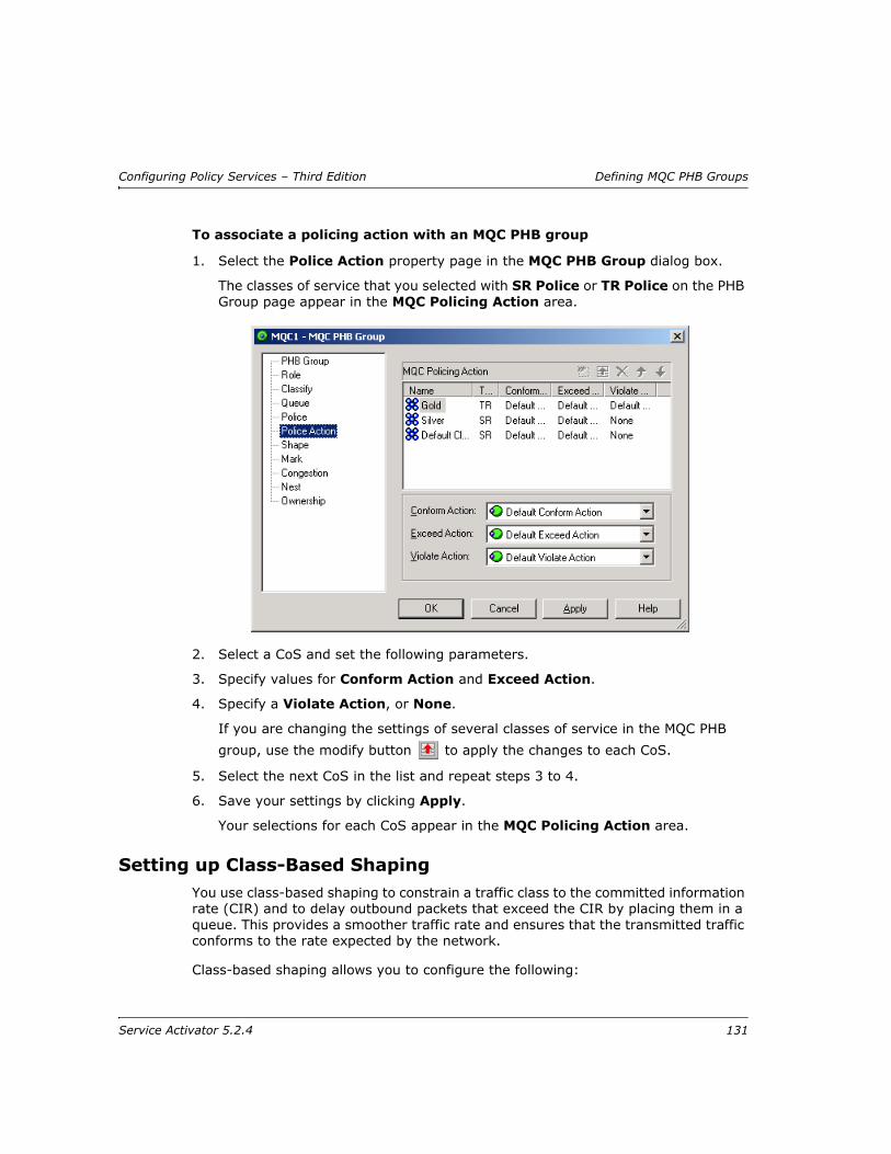
Configuring Policy Services – Third Edition Defining MQC PHB Groups
To associate a policing action with an MQC PHB group
1. Select the Police Action property page in the MQC PHB Group dialog box.
The classes of service that you selected with SR Police or TR Police on the PHB Group page appear in the MQC Policing Action area.
2. Select a CoS and set the following parameters.
3. Specify values for Conform Action and Exceed Action.
4. Specify a Violate Action, or None.
If you are changing the settings of several classes of service in the MQC PHB
group, use the modify button to apply the changes to each CoS.
5. Select the next CoS in the list and repeat steps 3 to 4.
6. Save your settings by clicking Apply.
Your selections for each CoS appear in the MQC Policing Action area.
Setting up Class-Based ShapingYou use class-based shaping to constrain a traffic class to the committed information rate (CIR) and to delay outbound packets that exceed the CIR by placing them in a queue. This provides a smoother traffic rate and ensures that the transmitted traffic conforms to the rate expected by the network.
Class-based shaping allows you to configure the following:
Service Activator 5.2.4 131
Defining MQC PHB Groups Configuring Policy Services – Third Edition
Average rate traffic shaping – limits the traffic rate to the CIR, non-Frame Relay interfaces only.
Peak rate traffic shaping – allows traffic rate bursts above the CIR if extra network bandwidth is available, packets may be dropped if network congestion occurs, non-Frame Relay interfaces only.
Adaptive generic traffic shaping for Frame Relay – utilizes the Backward Explicit network Congestion Notification (BECN) to estimate the available bandwidth and adjust the transmission rate accordingly. BECN signals may also be reflected as Forward Explicit network Congestion Notifications (FECN).
CB-WFQ inside GTS – places a packet that exceeds the shape parameters in a queue whose priority is based on bandwidth allocated to the CoS to which the packet belongs. CB-WFQ is configured on the Queue page.
Note: For complete dialog box and property page descriptions, refer to the Online Help.
To set up average or peak rate traffic shaping
1. Select the Shape property page on the MQC PHB Group dialog box.
The classes of service that you selected with Shape on the PHB Group page appear in the MQC Shaping area.
It is also possible to configure basic traffic shaping on Cisco 10000 devices. Contact Technical Support for details of interface support for basic traffic shaping – the capability is not reported in the user interface.
132 Service Activator 5.2.4

Configuring Policy Services – Third Edition Defining MQC PHB Groups
2. Select a CoS and set the following parameters.
3. Select either Shape Average or Shape Peak.
4. Specify values including CIR, Bc, and Be.
If you are changing the settings of several classes of service in the MQC PHB
group, use the Modify button to apply the changes to each CoS.
5. Select the next CoS in the list and repeat steps 3 to 4.
6. Specify Number of buffers. Select Device default to specify the default value for that particular device.
7. Configure the Frame relay related parameters
8. Save your settings by clicking Apply.
To set up adaptive generic traffic shaping
In addition to average or peak rate shaping, you can configure BECN and/or FECN adaptive shaping on Frame Relay interfaces.
1. Select the Shape property page on the MQC PHB Group dialog box.
Service Activator 5.2.4 133

Defining MQC PHB Groups Configuring Policy Services – Third Edition
The classes of service that you selected with Shape on the PHB Group page appear in the MQC Shaping area
2. Select a CoS and select either Shape Average or Shape Peak.
3. Specify values including CIR, Bc, and Be.
4. Specify Number of buffers. Select Device default to specify the default value for that particular device.
5. Select the FR Extension checkbox.
6. Select BECN Adapt and/or FECN Adapt.
7. Enter a minimum value for CIR in the Min CIR field.
8. Select the BECN Adapt checkbox if you want to monitor for Frame Relay frames that have the BECN bit set.
Select the FECN Adapt checkbox if you want to monitor for Frame Relay frames that have the FECN bit set.
If you are changing the settings of several classes of service in the MQC PHB
group, use the Modify button to apply the changes to each CoS.
9. For each CoS to which you wish to apply adaptive generic traffic shaping, repeat steps 2 to 8.
Your selections for each CoS appear in the MQC Shaping area.
10. Save your settings by clicking Apply.
To set up CB-WFQ within GTS
Class-based shaping can be used in conjunction with CB-WFQ. This allows a packet that exceeds the shape parameters to be placed in a queue whose priority and bandwidth allocation is defined by the packet’s CoS.
1. In the MQC PHB Group dialog box, select the PHB Group page.
2. Select a CoS to which you want to apply CB-WFQ within GTS.
3. Select CBWFQ and Shape.
4. Repeat steps 2 and 3 for each CoS to which you want to apply CB-WFQ within GTS.
5. Select the Queue page.
6. For each CoS, set up CB-WFQ as described in Setting up Class-Based Weighted Fair Queuing on page 124.
7. Select the Shape page.
8. For each CoS, set up GTS as described in To set up average or peak rate traffic shaping on page 132.
134 Service Activator 5.2.4

Configuring Policy Services – Third Edition Defining MQC PHB Groups
To set up basic traffic shaping
You can apply basic traffic shaping to Cisco 10000 devices, based on the CIR value only.
1. Select the Shape property page on the MQC PHB Group dialog box.
The classes of service that you selected with Shape on the PHB Group page appear in the MQC Shaping area
2. Select a CoS and select Default Shaping and specify a value in the CIR field.
3. Select the next CoS in the list and repeat step 2.
4. Save your settings by clicking Apply.
Setting up Class-Based MarkingYou can use class-based marking to mark packets so that they belong to a particular traffic class which can affect how the packets will be managed by QoS policies at other interfaces in the traffic path.
To set up class-based marking
1. Select the Mark property page in the MQC PHB Group dialog box.
The classes of service that you selected with Mark on the PHB Group page appear in the MQC Mark area.
Service Activator 5.2.4 135
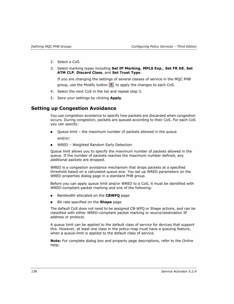
Defining MQC PHB Groups Configuring Policy Services – Third Edition
2. Select a CoS.
3. Select marking types including Set IP Marking, MPLS Exp., Set FR DE, Set ATM CLP, Discard Class, and Set Trust Type.
If you are changing the settings of several classes of service in the MQC PHB
group, use the Modify button to apply the changes to each CoS.
4. Select the next CoS in the list and repeat step 3.
5. Save your settings by clicking Apply.
Setting up Congestion AvoidanceYou use congestion avoidance to specify how packets are discarded when congestion occurs. During congestion, packets are queued according to their CoS. For each CoS you can specify:
Queue limit – the maximum number of packets allowed in the queue
and/or:
WRED – Weighted Random Early Detection
Queue limit allows you to specify the maximum number of packets allowed in the queue. If the number of packets reaches the maximum number defined, any additional packets are dropped.
WRED is a congestion avoidance mechanism that drops packets at a specified threshold based on a calculated queue size. You set up WRED parameters on the WRED properties dialog page in a standard PHB group.
Before you can apply queue limit and/or WRED to a CoS, it must be identified with WRED-compliant packet marking and one of the following:
Bandwidth allocated on the CBWFQ page
Bit rate specified on the Shape page
The default CoS does not need to be assigned CB-WFQ or Shape actions, and can be classified with either WRED-compliant packet marking or source/destination IP address or protocol.
A queue limit can be applied to the default class of service for devices that support this. However, at least one class in the policy-map must have a queuing feature, when a queue-limit is applied to the default class of service.
Note: For complete dialog box and property page descriptions, refer to the Online Help.
136 Service Activator 5.2.4

Configuring Policy Services – Third Edition Defining MQC PHB Groups
To set up congestion avoidance
1. Select the Congestion property page in the MQC PHB Group dialog box.
The classes of service that you selected with Congestion on the PHB Group page appear in the MQC Congestion area.
2. Select a CoS.
3. To specify a Queue Limit, select either Default, or Value.
4. From the WRED Strategy dropdown list select one of None, Router Default or <Name of a standard PHB group>.
5. If you are changing the settings of several classes of service in the MQC PHB group, use the Modify button to apply the changes to each CoS.
6. Select the next CoS in the list and repeat steps 3 to 4.
7. Save your settings by clicking Apply.
Service Activator 5.2.4 137

Defining MQC PHB Groups Configuring Policy Services – Third Edition
Nesting MQC PHB groupsA child MQC PHB group may be nested inside a parent MQC PHB group. This provides a method of applying a policy to a broad range of traffic, defined by the parent MQC PHB group, and another to a subset of that range, defined by the child MQC PHB group. For example, a single shaping policy may be applied to all traffic on an interface by a parent MQC PHB group, while the child applies a queuing policy to one or more classes of service. The resulting configuration is referred to by Cisco as a ‘hierarchical service policy’.
A child MQC PHB group may be nested for a CoS to which Policing, Shaping, CB- WFQ or LLQ is applied. The method for nesting MQC PHB groups is:
1. Create the child MQC PHB group
The child MQC PHB group defines Policing, Shaping or CB-WFQ parameters for a subset of traffic handled by an interface – for example, Gold traffic.
138 Service Activator 5.2.4
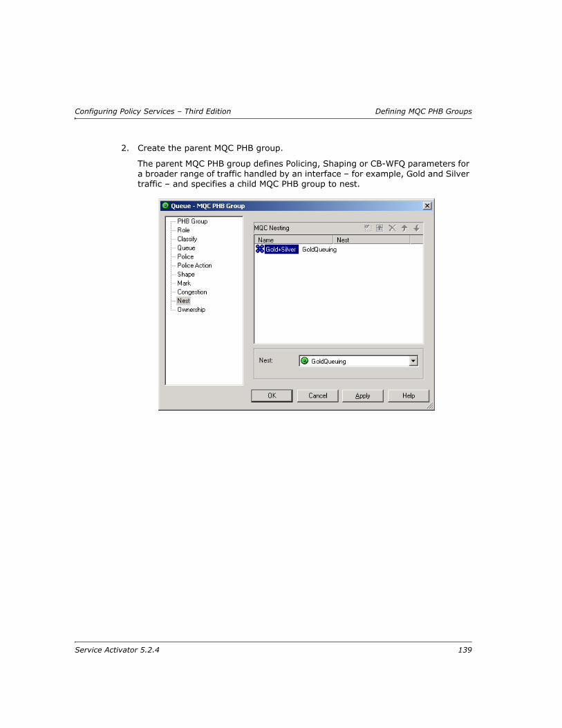
Configuring Policy Services – Third Edition Defining MQC PHB Groups
2. Create the parent MQC PHB group.
The parent MQC PHB group defines Policing, Shaping or CB-WFQ parameters for a broader range of traffic handled by an interface – for example, Gold and Silver traffic – and specifies a child MQC PHB group to nest.
Service Activator 5.2.4 139

Defining MQC PHB Groups Configuring Policy Services – Third Edition
At command level, an MQC PHB group is configured as a policy map, and a class of service is configured as a class map. Nesting places a policy map (a child MQC PHB group) within a class map (CoS) that is part of another policy map (a parent MQC PHB group).
This is illustrated in the following diagram:
Child MQC PHBgroup definition
Parent MQC PHBgroup definition
CoS (class map) towhich the parentMQC PHB group
applies
Child MQC PHB groupnested within the class
map
policy-map QueueGold
class Gold
bandwidth 30
policy-map Gold+SilverShape
class Gold+Silver
shape average 56000 28000 0
service-policy QueueGold
140 Service Activator 5.2.4

Configuring Policy Services – Third Edition Defining MQC PHB Groups
To nest MQC PHB groups
1. Select the Nest tab.
The classes of service that you selected with Nest and any combination of Shape, SR/TR Police or CBWFQ on the PHB Group page appear in the MQC Nesting area.
2. Select a CoS in the MQC Nesting area of the parent MQC PHB group.
3. Select the child MQC PHB group from the Nest drop down combo box.
4. If you are nesting several MQC PHB groups, click the modify button to apply each selection.
The name of the child MQC PHB group appears in the Nest column next to the selected CoS in the MQC Nesting area to indicate that the child policy map is nested within the selected class map.
5. Save your settings by clicking Apply.
Service Activator 5.2.4 141
Defining MQC PHB Groups Configuring Policy Services – Third Edition
RTP Header CompressionRTP (Real-Time Protocol) and RTCP (Real-Time Control Protocol) header compression is supported on out-going Frame Relay traffic on a Class-of-Service basis. It is used on relatively low-speed Frame Relay links to improve latency for Voice-over-IP traffic.
RTP Header Compression reduces the overhead on each voice packet that traverses the network. The near-constant nature of RTP and RTCP headers permits only the differences to be transmitted.
This feature is enabled in the Service Activator GUI by selecting the RTP Compression checkbox on the MQC PHB Group dialog box. It sends the following command to the router: “compression header ip rtp”.
The command is saved on the router in a policy map, under the class corresponding to the CoS selected by the user. A sample of the configuration saved on a router follows.
policy-map 1
class 1
priority 45
compress header ip rtp
142 Service Activator 5.2.4
Configuring Policy Services – Third Edition Implementing and Managing PHB Groups
Chapter 6
Implementing and Managing PHB Groups
This chapter describes how to implement and manage both standard and MQC PHB groups. The chapter:
Describes how to set up and manage PHB groups
Explains how to implement PHB groups and understand the information that Service Activator displays for implemented PHB groups
Service Activator 5.2.4 143
Implementing and Managing PHB Groups Configuring Policy Services – Third Edition
Implementing a PHB group
Associating a PHB group with a policy targetIf you set up a PHB group from the Policy tab, you can apply it to the appropriate points in the network by dragging and dropping. A PHB group can be applied to any policy target – that is, a network component, a customer, site or VPN.
To apply a PHB group to a policy target
With the PHB group displayed in the hierarchy pane and the target object in the details pane, drag the PHB group onto the target object.
To remove a PHB group from a policy target
1. Double-click on the policy target.
Service Activator lists the configuration associated with the policy target in the details pane.
2. In the Details pane, select the PHB Groups tab and select the PHB group to be removed.
PHB groups applied to the policy target are listed on a white background, PHB groups applied at a higher point in the hierarchy are listed on a gray background.
3. From the PHB group’s pop-up menu, select Unlink.
Committing the transactionAs you define PHB groups, they are added to the current transaction. Depending on your user access level, you may be able to commit the transaction immediately, or save it in a pending state for checking and committing by a supervisor. The policy implemented by a PHB group is not implemented until the transaction it forms part of is committed. For more information see Implementing policy on page 21.
Checking implemented PHB groupsOnce you have propagated PHB groups to devices throughout the network, you can check how and where PHB groups have been implemented.
Abstract and concrete PHB groupsA concrete PHB group is an implementation of a defined PHB group that applies to a specific point in the network, that is, at a particular interface, sub-interface or VC endpoint. Each abstract or parent PHB group set up can result in a number of concrete PHB groups.
144 Service Activator 5.2.4
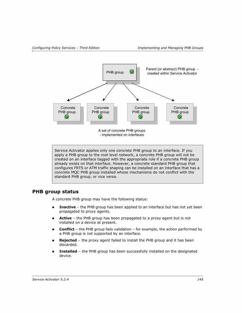
Configuring Policy Services – Third Edition Implementing and Managing PHB Groups
PHB group statusA concrete PHB group may have the following status:
Inactive – the PHB group has been applied to an interface but has not yet been propagated to proxy agents.
Active – the PHB group has been propagated to a proxy agent but is not installed on a device at present.
Conflict – the PHB group fails validation – for example, the action performed by a PHB group is not supported by an interface.
Rejected – the proxy agent failed to install the PHB group and it has been discarded.
Installed – the PHB group has been successfully installed on the designated device.
Service Activator applies only one concrete PHB group to an interface. If you apply a PHB group to the root level network, a concrete PHB group will not be created on an interface tagged with the appropriate role if a concrete PHB group already exists on that interface. However, a concrete standard PHB group that configures FRTS or ATM traffic shaping can be installed on an interface that has a concrete MQC PHB group installed whose mechanisms do not conflict with the standard PHB group, or vice versa.
PHB groupParent (or abstract) PHB group -created within Service Activator
A set of concrete PHB groups- implemented on interfaces
ConcretePHB group
ConcretePHB group
ConcretePHB group
ConcretePHB group
Service Activator 5.2.4 145
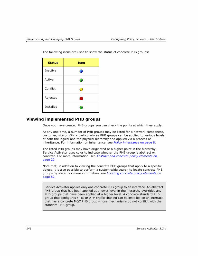
Implementing and Managing PHB Groups Configuring Policy Services – Third Edition
The following icons are used to show the status of concrete PHB groups:
Viewing implemented PHB groupsOnce you have created PHB groups you can check the points at which they apply.
At any one time, a number of PHB groups may be listed for a network component, customer, site or VPN – particularly as PHB groups can be applied to various levels of both the logical and the physical hierarchy and applied via a process of inheritance. For information on inheritance, see Policy inheritance on page 8.
The listed PHB groups may have originated at a higher point in the hierarchy. Service Activator uses color to indicate whether the PHB group is abstract or concrete. For more information, see Abstract and concrete policy elements on page 22.
Note that, in addition to viewing the concrete PHB groups that apply to a specific object, it is also possible to perform a system-wide search to locate concrete PHB groups by state. For more information, see Locating concrete policy elements on page 82.
Status Icon
Inactive
Active
Conflict
Rejected
Installed
Service Activator applies only one concrete PHB group to an interface. An abstract PHB group that has been applied at a lower level in the hierarchy overrides any PHB groups that have been applied at a higher level. A concrete standard PHB group that configures FRTS or ATM traffic shaping can be installed on an interface that has a concrete MQC PHB group whose mechanisms do not conflict with the standard PHB group.
146 Service Activator 5.2.4

Configuring Policy Services – Third Edition Implementing and Managing PHB Groups
To view the points at which a PHB group has been implemented
On the Policy tab, select the relevant PHB group and double-click the Compact List View or Report View button.
The points at which the selected PHB group applies are listed in the Details pane.
Each abstract (parent) PHB group is followed by a list of the concrete PHB groups that have been created at appropriate interfaces. The background color of a PHB group indicates where it was created. For more information see Managing PHB groups on page 149.
To view the PHB groups that apply to an object
1. On the Topology tab, double-click on the relevant policy target.
The rules and PHB groups that apply at the selected level can be viewed in the details pane.
2. Select the PHB Groups tab (the tabs that appear will depend on the object you have selected).
Each abstract (parent) PHB group is followed by a list of the concrete PHB groups that have been created at appropriate interfaces. The background color of a PHB group indicates where it was created. For more information see Managing PHB groups on page 149.
Information displayed about PHB groups
Click on the PHB groups tab to view relevant PHB groups. PHB group details are listed under the following headings:
Heading Description
Name Name of the PHB group.
State Current status of the concrete PHB group.
Level For abstract PHB groups, the level at which the PHB group was created (the name of the domain, VPN, site, device, interface or VC endpoint). For concrete PHB groups, the object on which the PHB group is installed.
Type Either PHB Group or MQC PHB Group.
Device Role Name of the matched device role to which the PHB group is applied.
Service Activator 5.2.4 147
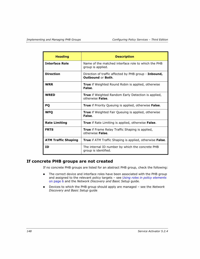
Implementing and Managing PHB Groups Configuring Policy Services – Third Edition
If concrete PHB groups are not createdIf no concrete PHB groups are listed for an abstract PHB group, check the following:
The correct device and interface roles have been associated with the PHB group and assigned to the relevant policy targets – see Using roles in policy elements on page 6 and the Network Discovery and Basic Setup guide.
Devices to which the PHB group should apply are managed – see the Network Discovery and Basic Setup guide
Interface Role Name of the matched interface role to which the PHB group is applied.
Direction Direction of traffic affected by PHB group - Inbound, Outbound or Both.
WRR True if Weighted Round Robin is applied, otherwise False.
WRED True if Weighted Random Early Detection is applied, otherwise False.
PQ True if Priority Queuing is applied, otherwise False.
WFQ True if Weighted Fair Queuing is applied, otherwise False.
Rate Limiting True if Rate Limiting is applied, otherwise False.
FRTS True if Frame Relay Traffic Shaping is applied, otherwise False.
ATM Traffic Shaping True if ATM Traffic Shaping is applied, otherwise False.
ID The internal ID number by which the concrete PHB group is identified.
Heading Description
148 Service Activator 5.2.4

Configuring Policy Services – Third Edition Implementing and Managing PHB Groups
Managing PHB groups
Changing the sequence order of PHB groupsThe abstract and inherited PHB groups that apply to a policy target are listed in the following order:
Abstract PHB groups – PHB groups applied at the object
Inherited PHB groups – PHB groups that have been applied to an object at a higher level in the hierarchy and inherited to the lower-level object
Inherited PHB groups are further subdivided according to where the corresponding abstract PHB group was applied. For example, PHB groups inherited from devices are grouped together.
The order in which PHB groups are listed in the details pane is important – the first PHB group that appears in the list is applied. Service Activator applies only one concrete PHB group to any interface. Therefore, you need to ensure that PHB groups appear in the correct order.
The initial order reflects the order in which the PHB groups were created. You can change the order if required, by dragging and dropping PHB groups to a new position in the list.
PHB Group map-class namesThe Cisco device driver uses frame-relay map-classes to implement the following Service Activator policy elements:
Frame Relay Traffic Shaping (FRTS) / FRF.12 PHB groups
WFQ / WFQ with WRED PHB groups on frame-relay interfaces
MQC PHB groups on frame-relay interfaces
WRR PHB groups on frame-relay interfaces
PQ PHB groups on frame-relay interfaces
Classification rules on frame-relay interfaces (only if MQC is supported)
The default action for the Cisco driver is to automatically generate frame-relay class-map names.
PHB groups applied at the policy target always override those inherited from a higher point in the hierarchy. Service Activator therefore prevents you from moving inherited PHB groups above abstract PHB groups at a policy target.
Service Activator 5.2.4 149

Implementing and Managing PHB Groups Configuring Policy Services – Third Edition
Manual specification of Cisco frame-relay map class namesCisco frame-relay map class names can be created from information specified manually in Service Activator object names (i.e. PFB groups), instead of being automatically generated as described above.
For detailed information, see the Cisco Device Driver Guide.
Valid class-map names
Care must be taken in how data upon which map class names are generated is specified, so that the concatenated map class names are valid.
The Cisco naming convention for map classes is as follows:
space::= One or more space chars
char::= ([a-z]|[A-Z]|[!£$%^&*()-_+={}[]:;@'~#`\|/.>,<]|[\"])
name::= "char+"|"char(char|space)+char"
In addition, the following guidelines should be followed for PBF groups whose names will be used in the creation of map class names by the Cisco driver:
If a double quote (i.e. ") character is required in a group name then it must be preceded by a backslash. For example, \"
Do not include leading or trailing whitespace in group names
Avoid using the question mark (“?”) character in group names
150 Service Activator 5.2.4

Configuring Policy Services – Third Edition Implementing and Managing PHB Groups
About Configuration PoliciesService Activator supports the use of extensible VPN-related Configuration Policies which are implemented through the Configuration Policy functionality of the Service Activator GUI. You can access the Configuration Policies through the Configuration Policy Dialog Box for Customer, Site, Network, Device, Interface or Sub-interface objects. The information gathered through the HTML interface is configured on devices through the Network Processor.
Adding a new Configuration PolicyPrerequisite: New Configuration Policies must be installed before you can add them in the GUI. Refer to the configuration policy installation procedure in the Setup Guide.
To add a new Configuration Policy: Click either the Service or Topology tab. Locate the Customer, Site, Network, Device, Interface or Sub-interface, right click it, and select Add Configuration Policy from the pop-up menu.
The Configuration Policy dialog box displays the properties of a selected Configuration Policy, which allows the entry of either a set of raw XML commands, or an HTML-based entry form to collect information which is then converted to XML. The XML commands are passed to the Network Processor.
See the Service Activator Online Help for more information.
Service Activator 5.2.4 151

Implementing and Managing PHB Groups Configuring Policy Services – Third Edition
152 Service Activator 5.2.4

Configuring Policy Services – Third Edition Example Policy Setups
Chapter 7
Example Policy Setups
This chapter provides some examples that illustrate Service Activator’s ability to apply policy at any point in the network and at any network component. The chapter:
Demonstrates how to target policy to the appropriate points in the network using roles
Shows how to apply policy to a VC endpoint
Illustrates the use of classifications and classification groups in rules
Service Activator 5.2.4 153

Example Policy Setups Configuring Policy Services – Third Edition
Using roles to apply policyThis example looks at QoS requirements across the core network and examines Service Activator’s solution at one point in the network.
RequirementsThe requirements are as follows:
Provide two service packages, Premium and Basic
Support a range of customers
Ensure that bandwidth restrictions are applied to incoming and outgoing customer traffic
Maintain traffic flow in the core network
In both the Premium and the Basic service packages there are three classes of service – Gold, Silver and Bronze. The bandwidth percentage allocated to each CoS differs between service package:
Premium traffic receives 30% Gold, 30% Silver, 40% Bronze
Basic traffic receives 10% Gold, 40% Silver, 50% Bronze
Traffic entering the core network must be restricted to a bandwidth limit agreed on a per-customer basis. Links coming into the core differ in their bandwidth capacity.
154 Service Activator 5.2.4

Configuring Policy Services – Third Edition Example Policy Setups
These requirements are illustrated in the following diagram:
SolutionFrom the requirements, it is possible to identify three variables that affect policy:
Service package
Bandwidth capacity of the link
Customer
These variables dictate the roles that must be created to target policy to the appropriate points in the network. Ideally, three sets of roles would be created to support these variables. However, Service Activator allows a maximum of one system and/or one user-defined role to be assigned to a policy element (though you can assign one system and any number of user-defined roles to a policy target). In the roles we create, therefore, service package and bandwidth will be combined into a single role.
Branch Site
InternetGateway
Site
Branch SitePE2
CoreNetworkQueue traffic in
the core networkHQ Site
Classify and markcustomer traffic by
service package beforeit enters the core network
PE3PE1
P1
CE3CE1
CE4
Branch Site
Regulate traffic load onthe CE site and enforcethe service package'sbandwidth restrictions
Queuing
CE2
Ethernet
Internet
Mark internettraffic for
separate billing
Service Activator 5.2.4 155
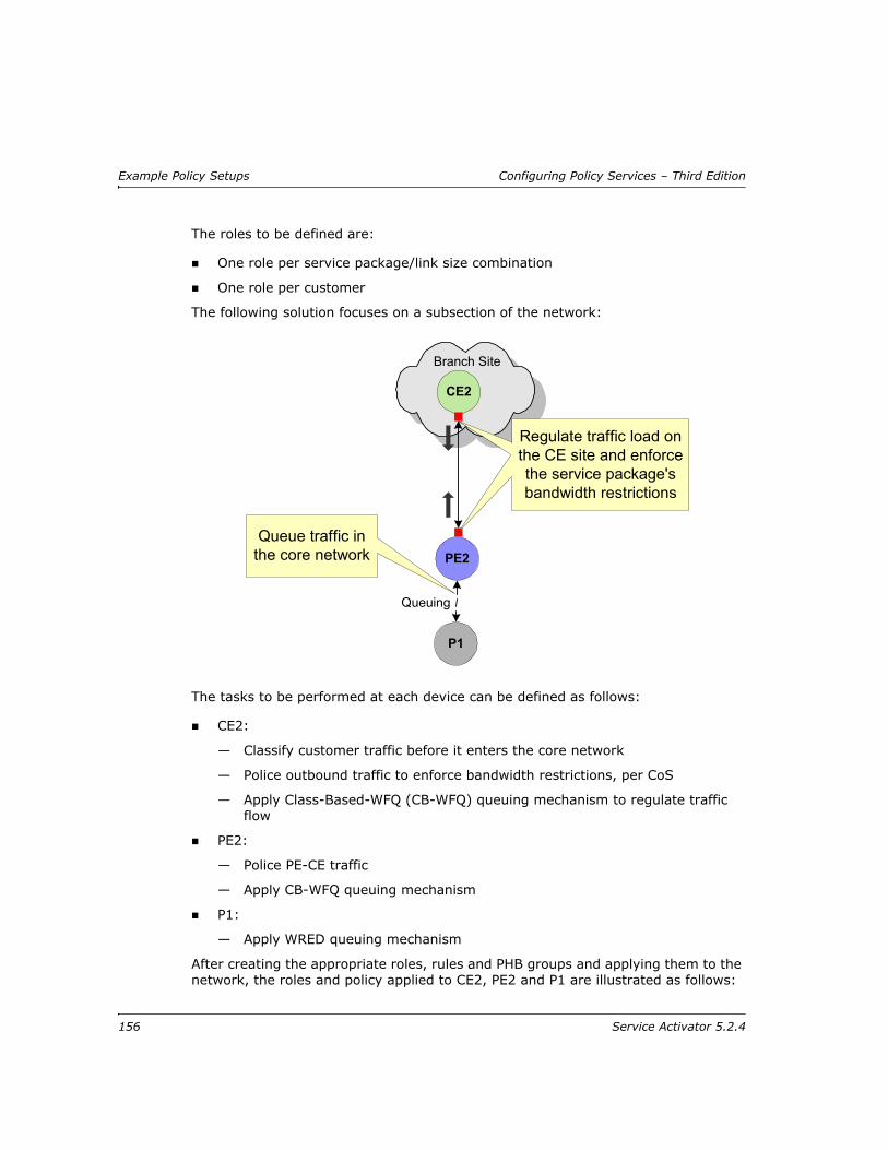
Example Policy Setups Configuring Policy Services – Third Edition
The roles to be defined are:
One role per service package/link size combination
One role per customer
The following solution focuses on a subsection of the network:
The tasks to be performed at each device can be defined as follows:
CE2:
— Classify customer traffic before it enters the core network
— Police outbound traffic to enforce bandwidth restrictions, per CoS
— Apply Class-Based-WFQ (CB-WFQ) queuing mechanism to regulate traffic flow
PE2:
— Police PE-CE traffic
— Apply CB-WFQ queuing mechanism
P1:
— Apply WRED queuing mechanism
After creating the appropriate roles, rules and PHB groups and applying them to the network, the roles and policy applied to CE2, PE2 and P1 are illustrated as follows:
Branch Site
PE2Queue traffic in
the core network
Regulate traffic load onthe CE site and enforcethe service package'sbandwidth restrictions
Queuing
CE2
P1
156 Service Activator 5.2.4

Configuring Policy Services – Third Edition Example Policy Setups
Applying policy to a VC endpointOne of the advantages of Service Activator’s role-based application of policy is the ability to assign roles to any network component, including sub-interfaces and VC endpoints. This enables you to apply policy to a sub-interface or VC endpoint independent of its parent interface.
In this example, two VC endpoints on the same device are connected to two Permanent Virtual Circuits (PVC) that have different bandwidth capacity. CB-WFQ must be applied to both PVCs, with bandwidth weight defined in Kbits/s.
The following diagram presents a physical representation of the relevant network section.
CE2(Access)
PE2(Gateway)cust_A_class
64K link
Core
P1(Core)
Core
servpkg_prem_64k
AccessAccess
servpkg_prem_64k
PHB group(WRED)'core_WRED_PHB'Device role:
Core
Any Role
Interface role:
PHB group'Prem_64K_PHB'Device role:
servpkg_prem_64k
Access
Any Role
Interface role:
Service Activator 5.2.4 157

Example Policy Setups Configuring Policy Services – Third Edition
To take account of each PVC’s bandwidth capacity, two PHB groups must be created and each PHB group targeted at the correct VC endpoint. This can be achieved by assigning a different role to each VC endpoint and associating the relevant role with the correct PHB group.
The following diagram shows the logical network setup, with PHB groups defined and targeted at the appropriate VC endpoint using roles:
CE PEPVC 1
PVC 2
Frame Relaynetwork
FrameRelayswitch
FrameRelayswitch
128KB
2MB
CB-WFQ
CB-WFQ
P
158 Service Activator 5.2.4

Configuring Policy Services – Third Edition Example Policy Setups
Using classifications in rulesA classification provides a means of categorizing traffic according to its source and destination and traffic type. You can create standalone classifications and/or group a number of classifications to form a classification group. Members of a classification group do not need to share the same source and destination point or traffic type. Classifications and/or classification groups can be associated with a rule to define the traffic to which it applies.
In this example a set of Web-based application servers supply information to employees. Employees also have Internet access. The requirement is to apply a different CoS treatment to traffic to and from the application servers and the Internet.
The network setup is shown in the following diagram:
CE PE128KB
link_128KB
PCoreAccess
core_2MB
2MBPVC 1 PVC 2
PHB group (CB-WFQ)'2MB_PHB'Device role:
core_2MB
Core
Gateway
Interface role:
PHB group (CB-WFQ)'128KB_PHB'Device role:
link_128KB
Access
Gateway
Interface role:
Service Activator 5.2.4 159
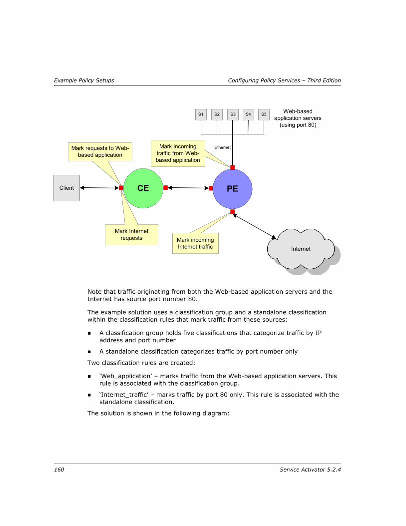
Example Policy Setups Configuring Policy Services – Third Edition
Note that traffic originating from both the Web-based application servers and the Internet has source port number 80.
The example solution uses a classification group and a standalone classification within the classification rules that mark traffic from these sources:
A classification group holds five classifications that categorize traffic by IP address and port number
A standalone classification categorizes traffic by port number only
Two classification rules are created:
‘Web_application’ – marks traffic from the Web-based application servers. This rule is associated with the classification group.
‘Internet_traffic’ – marks traffic by port 80 only. This rule is associated with the standalone classification.
The solution is shown in the following diagram:
CE PE
S1 Web-basedapplication servers
(using port 80)
Client
S2 S4S3 S5
Ethernet
Internet
Mark incomingtraffic from Web-based application
Mark incomingInternet traffic
Mark Internetrequests
Mark requests to Web-based application
160 Service Activator 5.2.4

Configuring Policy Services – Third Edition Example Policy Setups
Note that at the CE device, rules must be applied in the following order:
1. Web_application
2. Internet_traffic
Rule order is significant at this point as the interface handles both Web-based application traffic and Internet traffic. Therefore, the most specific rule must be applied first (classifying by both IP address and port number) before the more general rule (port number only). If the rules are applied in the incorrect order, both Web-based application traffic and Internet traffic will be classified by the Internet_traffic rule as both use port 80.
Copying Classification, Policing and Access rulesIt is possible to quickly copy and paste Classification, Policing, and Access rules between objects in the same domain. This makes it simple to re-create the settings for a rule on another object, without having to access a lot of property pages.
1. Double-click on the item which has the source rule already applied to it.
2. Select the appropriate tab — either Classification Rules, Policing Rules, or Access Rules — in the Details pane to show the rule to be copied.
S...Classification
S...Classification
S...Classification
S2 IP address/port 80Classification
S1 IP address/port 80Classification
HTTP (port 80)Classification
CE PE
S1 Web-basedapplication servers
(using port 80)
Client
S2 S4S3 S5
Ethernet
Internet
Classification rule'Web_application'
Classification rule'Internet_traffic'
Classificationperformed at PEdevice - site directlyconnected by Ethernet
Classificationgroup
Service Activator 5.2.4 161

Example Policy Setups Configuring Policy Services – Third Edition
3. Select the source rule and click either click the copy icon in the toolbar, or select Edit > Copy.
4. Double-click the target item to which you want copy the rule.
5. Ensure the appropriate tab in the Details window is still selected, and click inside the Details pane. The enables the Paste button in the toolbar.
6. Click the Paste button in the toolbar, or select Edit > Paste.
The rule is copied to the destination object. Modify the roles and values of the newly copied rule as you wish.
162 Service Activator 5.2.4

Configuring Policy Services – Third Edition Index
Index
Numerics802.1p user priority
basic data set-up 39description 28
AAbstract
PHB groups, description of 144policy elements, description of 22
Access Control Lists See ACLsAccess rules
copying 75introduction 70re-ordering 84viewing 79See also Rules
Accountscreating 54creating from sites 57group 56host 55user 55
ACLscontrolling number generated with aggregation 51specify name or number of 48
advanced.policy filecodepoints defined in 32, 39
Aggregationand nested class maps 52apply to match statements in a CoS 50controls number of ACLs generated 51
Alcatel devicesalcatel.policy file 26applying QoS 21
Application traffic type 40Assured Forwarding 32ATM
PHB group 105See also PHB groups
BBandwidth guarantee 65Burst size, in policing rules 68
CCAR, on Cisco devices 20CB WFQ See Class-Based WFQChecking implemented rules 76Cisco devices
Custom Queuing 97GTS 99marking packets 20NBAR 41Priority Queuing 98traffic types 40WFQ 102WRED 100WRR 97
Class of service data, description of 27Class-based marking, setting up 135Class-based policing
in MQC PHB groups 125set up single rate 126set up two rate 127
Class-based shapingin MQC PHB groups 131
Class-Based WFQin MQC PHB Groups 124in PHB groups 103
Classes of serviceaggregating match statements 50associating codepoints 37creating 36defined in advanced.policy file 39defined in default.policy file 38
Service Activator 5.2.4 163
Index Configuring Policy Services – Third Edition
description 28introduction 35match all or one match criteria 48policy configuration files 36
Classification groupsand MQC PHB groups 47creating 52See also Classifications
Classification rulescreating 66introduction 64re-ordering 84viewing 78See also Rules
Classificationsand MQC PHB groups 47creating 52description of 46example use 159See also Classification groups
Codepointsadvanced.policy file 32and CoS 29, 30creating 33
Committed rate, in policing rules 68Compound traffic type, creating 44Concrete PHB groups
description of 144status of 145
Concrete PHB groups, viewing 22Concrete policy elements
description of 22Concrete policy elements, description of 22Concrete rules
description of 76status of 77
Configuration filesjuniper.policy 26
Conflict avoidance in rules 85Congestion avoidance
setting up 136Copying
rules 75Creating
access rules 71account groups 56accounts 54
classes of service 36classification groups 52classification rules 66classifications 52codepoints 33MQC PHB groups 118PHB groups 95policing rules 69
Custom Queuing, PHB groups 97customer support ix
DDate and time templates
creating 53description of 40
default.policy fileand traffic types 41classes of service defined in 38
DeletingIP protocols 54
Device drivers, traffic types supported by 40Device types, support for rules 64Devices
traffic types supported by 40DiffServ codepoints
defined in default.policy file 32packet marking 29
DiffServ codepoints, description of 29Disabling rules 86Discard Eligibility bit 104Distributed Traffic Shaping 92, 109documentation
downloading xService Activator xi
Domain traffic type 40Driver scripts
using roles in 6DTS 92, 109
EExample policy setups 153–161Excess burst size, in policing rules 68Expedited Forwarding 32
FFiles
advanced.policy 32, 39alcatel.policy 26
164 Service Activator 5.2.4

Configuring Policy Services – Third Edition Index
default.policy 38juniper.policy 26Role_Assignment_Rules.policy 26Rule_and_PHB.policy 26
Filteringtraffic 70
Flow-Based WFQ, in PHB groups 103Frame Relay
Frame Relay Traffic ShapingSee FRTS
Frame Relay DE bit 104FRTS
PHB group 107See also PHB groups
FRTS on distributed platforms 109
GGroup traffic type, setting up 44GTS, and rate limiting 99
HHost accounts, creating 55
IImplemented PHB groups
information displayed for 147viewing 146
Implemented ruleschecking 76information displayed for access rules 79information displayed for classification rules 78information displayed for policing rules 80viewing 77
Inheritancepolicy 8
Interfacessupport for rules 63
IP protocolsadding 54restoring 54setting up 54view details 54
JJuniper devices
applying QoS 20create example DiffServ codepoints, etc 26
juniper.policy file 26juniper.policy file 26
LLLQ, configuring with MQC PHB groups 122Low Latency Queuing See LLQ
MMarking packets on Cisco routers 20MIME traffic type, setting up traffic types 40Modular QoS CLI, and MQC PHB groups 112Moving
PHB groups in details pane 149rules in details pane 84
MPLS experimental bitsdefined by advanced.policy file 33description of 30packet marking 30
MPLS Topmost experimental bitsdescription of 31
MQC PHB groups 111–141and classifications 47and Modular QoS CLI 112class-based marking 135class-based policing 125class-based shaping 131configuring Class-Based WFQ 124configuring LLQ 122congestion avoidance 136nesting 138preparation 116set up policing action 129setting up 118specifying CoS evaluation order 120supported traffic management mechanisms 115
NNBAR
and marking on Cisco routers 20and traffic types on Cisco devices 41
PPacket limit, in PHB groups 98Packet marking, traffic type 40Packet markings
creating 33creating with policy files 26, 29
Service Activator 5.2.4 165

Index Configuring Policy Services – Third Edition
defined in policy configuration files 26, 29DiffServ codepoints
description of 29MPLS experimental bits 30MPLS Topmost experimental bits 31role of 28
PHB groupsapplying to policy targets 144creating 95implementing 21information displayed for implemented 147MQC See MQC PHB groups 111overview of 90policing and CoS 36PQ 98queuing mechanisms 90, 93Rate Limiting 99re-ordering 149traffic shaping mechanisms 91using roles in 6, 94, 118VC mechanisms 91viewing implemented 146WFQ 102WRED 100
Policing action, setting up 129Policing rules
creating 69implementing 21purpose 68re-ordering 84viewing 80See also Rules
Policing, setting up class-based 125Policy See QoS policyPort numbers and traffic type definitions 41Port traffic type 40PQ CB-WFQ, applying at access router 104Priority Queuing, PHB groups 98products
downloading xPropagating
PHB groups 144rules 76
QQoS mechanisms 93QoS policy
devising 10–21
example application to VC endpoint 157example role use 154example setups 153–161inheritance 8inheritance of policy 8on Alcatel devices 21on Juniper devices 20overview of building blocks 2policy roles 5
Queuing mechanismssupported by Service Activator 91
RRate Limiting, PHB groups 99Re-ordering
PHB groups 149rules 84
Restoring IP protocols 54Role assignment rules
create example rules 26Role_Assignment_Rules.policy file 26
Role_Assignment_Rules.policy file 26Roles
example use 154using in PHB groups 94, 118using in policy elements 6using in rules 64
RTP Compression 118, 142Rule components, overview 39Rules
abstract and concrete 76access rules 70checking implemented 76classification rules 64concrete, locating by type and status 82conflict avoidance 85disabled 76disabling 86example classifications use 159implementing 76managing 84overview of 60policing rules 68propagating 76re-ordering 84status 76status and precedence 76support by device types 64
166 Service Activator 5.2.4

Configuring Policy Services – Third Edition Index
support on an interface 63using roles in 6, 64viewing implemented 77viewing statistics summary of 82viewing system statistics for 81where applied 61
SSearching for concrete rules 82Setting up
access rules 70classification rules 64MQC PHB groups 118PHB groups 95policing rules 68
SharedPolicyData.policy filerestore IP protocols with 54
Single rate class-based policing, setting up 126
Sitescreating accounts from 57
Statistics pane, viewing 82Status
concrete rules 77PHB groups 146
Status barSystem Configuration field 21
Sub-application traffic type 40support
customer ixSystem Configuration, on status bar 21System Statistics window, opening 81
TTopmost experimental bits, MPLS 31Traffic classifications See ClassificationsTraffic management mechanisms, supported
by MQC PHB groups 115Traffic shaping mechanisms 91
ATM traffic shaping 105Frame Relay Traffic Shaping 107
Traffic typeapplication 40compound 44default 42device support for 40domain 40group, creating 45
MIME 40packet marking 40port 40setting up 40sub-application 40supported by devices 40URL 40
Trust Type 28Two rate class-based policing, setting up 127
UURL traffic type 40User accounts, creating 55
VVC endpoints
example policy application 157Viewing
implemented PHB groups 146implemented rules 77
WWeighted Fair Queuing See WFQWeighted Random Early Detection See WREDWeighted Round Robin See WREDWFQ
class-based in PHB groups 103flow-based 103PHB groups 102
WRED, PHB groups 100WRR
PHB groups 97
Service Activator 5.2.4 167

Index Configuring Policy Services – Third Edition
168 Service Activator 5.2.4


