Americas Headquarters: Cisco Systems, Inc., 170 West Tasman Drive, San Jose, CA 95134-1706 USA Configuring SNA Switching Services This chapter describes SNA Switching Services (SNASw), which supersedes all functionality previously available in the Advanced Peer-to-Peer Networking (APPN) feature in the Cisco IOS software. SNASw configuration will not accept the previous APPN configuration commands. Previous APPN users should use this chapter to configure APPN functionality using the new SNASw commands. For a complete description of the SNASw commands mentioned in this chapter, refer to the “SNA Switching Services Commands” chapter of the Cisco IOS Bridging and IBM Networking Command Reference (Volume 2 of 2). To locate documentation of other commands that appear in this chapter, use the command reference master index or search online. This chapter contains the following sections: • Technical Overview, page 1 • SNASw Configuration Task List, page 9 • Verifying SNASw, page 13 • Monitoring and Maintaining SNASw, page 13 • Troubleshooting Tips, page 14 • SNASw Configuration Examples, page 15 To identify the hardware platform or software image information associated with a feature, use the Feature Navigator on Cisco.com to search for information about the feature or refer to the software release notes for a specific release. For more information, see the “Identifying Platform Support for Cisco IOS Software Features” section on page lv in the “Using Cisco IOS Software” chapter. Technical Overview SNASw provides an easier way to design and implement networks with Systems Network Architecture (SNA) routing requirements. Previously, this network design was accomplished using APPN with full network node (NN) support in the Cisco router. This type of support provided the SNA routing functionality needed, but was inconsistent with the trends in Enterprise networks today. The corporate intranet is replacing the SNA WAN. Enterprises are replacing their traditional SNA network with an IP infrastructure that supports traffic from a variety of clients, using a variety of protocols, requiring access to applications on a variety of platforms, including SNA applications on enterprise servers.
Transcript
Americas Headquarters:Cisco Systems, Inc., 170 West Tasman Drive, San Jose, CA 95134-1706 USA
Configuring SNA Switching Services
This chapter describes SNA Switching Services (SNASw), which supersedes all functionality previously available in the Advanced Peer-to-Peer Networking (APPN) feature in the Cisco IOS software. SNASw configuration will not accept the previous APPN configuration commands. Previous APPN users should use this chapter to configure APPN functionality using the new SNASw commands.
For a complete description of the SNASw commands mentioned in this chapter, refer to the “SNA Switching Services Commands” chapter of the Cisco IOS Bridging and IBM Networking Command Reference (Volume 2 of 2). To locate documentation of other commands that appear in this chapter, use the command reference master index or search online.
This chapter contains the following sections:
• Technical Overview, page 1
• SNASw Configuration Task List, page 9
• Verifying SNASw, page 13
• Monitoring and Maintaining SNASw, page 13
• Troubleshooting Tips, page 14
• SNASw Configuration Examples, page 15
To identify the hardware platform or software image information associated with a feature, use the Feature Navigator on Cisco.com to search for information about the feature or refer to the software release notes for a specific release. For more information, see the “Identifying Platform Support for Cisco IOS Software Features” section on page lv in the “Using Cisco IOS Software” chapter.
Technical OverviewSNASw provides an easier way to design and implement networks with Systems Network Architecture (SNA) routing requirements. Previously, this network design was accomplished using APPN with full network node (NN) support in the Cisco router. This type of support provided the SNA routing functionality needed, but was inconsistent with the trends in Enterprise networks today. The corporate intranet is replacing the SNA WAN. Enterprises are replacing their traditional SNA network with an IP infrastructure that supports traffic from a variety of clients, using a variety of protocols, requiring access to applications on a variety of platforms, including SNA applications on enterprise servers.
Configuring SNA Switching Services Technical Overview
2
While SNA routing is still required when multiple servers must be accessed, the number of nodes required to perform this function is decreasing as the IP infrastructure grows and as the amount of native SNA traffic in the network decreases.
SNASw enables an enterprise to develop their IP infrastructure, while meeting SNA routing requirements.
The number of NNs in the network and the amount of broadcast traffic are reduced. Configuration is simplified, and SNA data traffic can be transported within the IP infrastructure. The following features provide this functionality:
• High Performance Routing (HPR)-Capable SNA Routing Services, page 2
• Branch Extender, page 2
• Enterprise Extender (HPR/IP), page 3
• Usability Features, page 4
• Management Enhancements, page 5
• LAN and IP-Focused Connection Types, page 6
High Performance Routing (HPR)-Capable SNA Routing ServicesSNASw provides the following SNA routing functions:
• Routes SNA sessions between clients and target SNA data hosts.
• Controls SNA traffic in a multiprotocol environment in conjunction with other Cisco IOS quality of service (QoS) features.
• Supports networks with a high proportion of SNA traffic and multiple enterprise servers, especially those that continue to support the traditional SNA endstation platform and new client types.
• Supports all types of SNA application traffic including traditional 3270 and peer LU 6.2.
• Supports an OS/390 Parallel Sysplex configuration, working in conjunction with the IBM Communications Server for S/390 (formerly VTAM) and the MVS Workload Manager, to provide higher availability in the data center using the HPR feature.
• Supports System Services Control Point (SSCP) services to downstream SNA devices using the Dependent LU Requester (DLUR) feature.
• Provides dynamic link connectivity with or without connection networks (CNs), which eliminates much of the configuration required in networks with numerous data hosts.
Branch Extender The Branch Extender (BEX) function enhances scalability and reliability of SNA routing nodes by eliminating topology updates and broadcast directory storms that can cause network instability. BEX appears as an NN to downstream end node (EN), low-entry networking (LEN) node, and PU 2.0 devices, while also appearing as an EN to upstream devices. The BEX function eliminates APPN topology and APPN broadcast search flows between SNASw nodes and the SNA data hosts in the network. This feature is key to providing a reliable turn-key installation because the network administrator no longer needs to develop in-depth knowledge of the level and characteristics of broadcast directory search and topology update traffic in the network. Such knowledge and analysis was commonly required to build successful networks utilizing NN technology without BEX.
Configuring SNA Switching Services Technical Overview
3
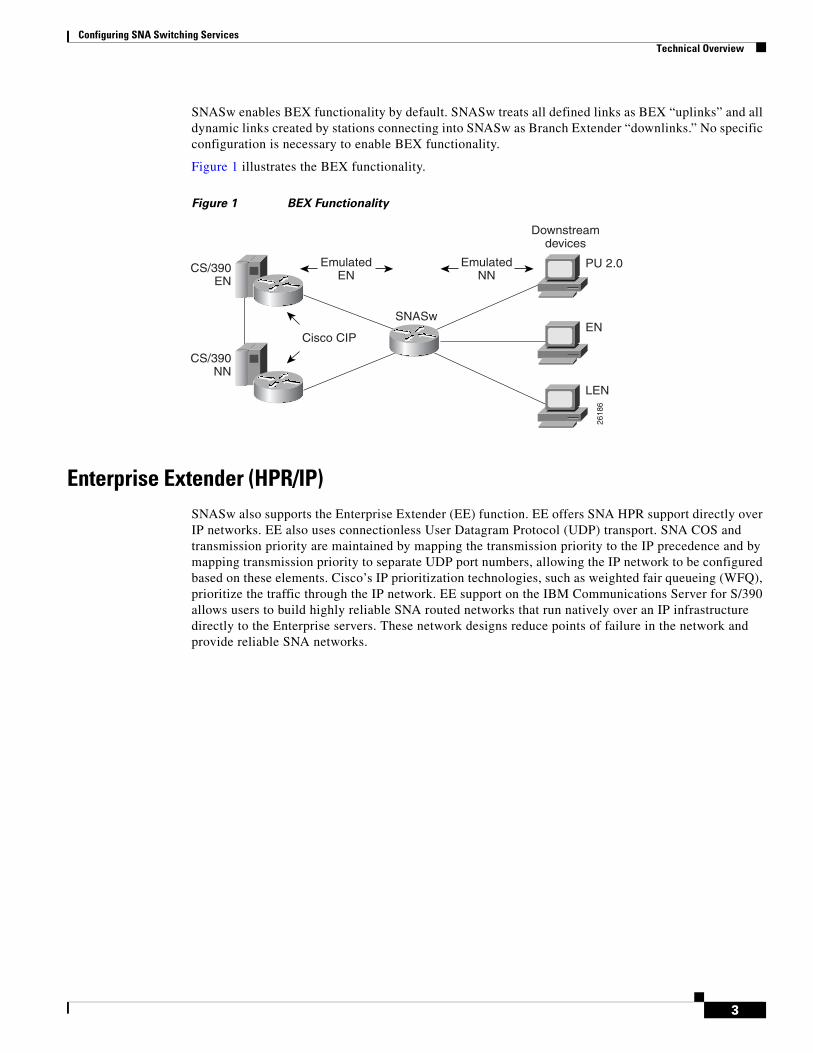
SNASw enables BEX functionality by default. SNASw treats all defined links as BEX “uplinks” and all dynamic links created by stations connecting into SNASw as Branch Extender “downlinks.” No specific configuration is necessary to enable BEX functionality.
Figure 1 illustrates the BEX functionality.
Figure 1 BEX Functionality
Enterprise Extender (HPR/IP)SNASw also supports the Enterprise Extender (EE) function. EE offers SNA HPR support directly over IP networks. EE also uses connectionless User Datagram Protocol (UDP) transport. SNA COS and transmission priority are maintained by mapping the transmission priority to the IP precedence and by mapping transmission priority to separate UDP port numbers, allowing the IP network to be configured based on these elements. Cisco’s IP prioritization technologies, such as weighted fair queueing (WFQ), prioritize the traffic through the IP network. EE support on the IBM Communications Server for S/390 allows users to build highly reliable SNA routed networks that run natively over an IP infrastructure directly to the Enterprise servers. These network designs reduce points of failure in the network and provide reliable SNA networks.
CS/390EN
CS/390NN
Downstreamdevices
SNASw
PU 2.0
ENCisco CIP
LEN
2618
6
EmulatedEN
EmulatedNN
Configuring SNA Switching Services Technical Overview
4
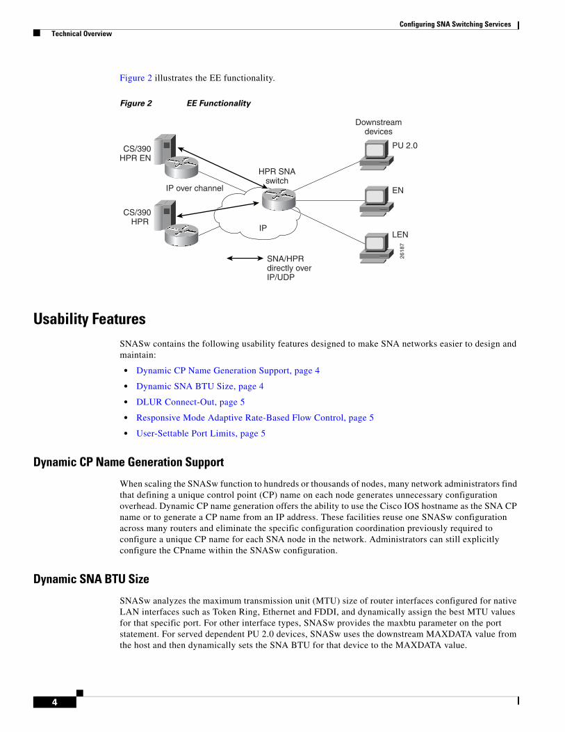
Figure 2 illustrates the EE functionality.
Figure 2 EE Functionality
Usability FeaturesSNASw contains the following usability features designed to make SNA networks easier to design and maintain:
When scaling the SNASw function to hundreds or thousands of nodes, many network administrators find that defining a unique control point (CP) name on each node generates unnecessary configuration overhead. Dynamic CP name generation offers the ability to use the Cisco IOS hostname as the SNA CP name or to generate a CP name from an IP address. These facilities reuse one SNASw configuration across many routers and eliminate the specific configuration coordination previously required to configure a unique CP name for each SNA node in the network. Administrators can still explicitly configure the CPname within the SNASw configuration.
Dynamic SNA BTU Size
SNASw analyzes the maximum transmission unit (MTU) size of router interfaces configured for native LAN interfaces such as Token Ring, Ethernet and FDDI, and dynamically assign the best MTU values for that specific port. For other interface types, SNASw provides the maxbtu parameter on the port statement. For served dependent PU 2.0 devices, SNASw uses the downstream MAXDATA value from the host and then dynamically sets the SNA BTU for that device to the MAXDATA value.
CS/390HPR EN
CS/390HPR
Downstreamdevices
HPR SNAswitch
PU 2.0
EN
IP
IP over channel
LEN
2618
7
SNA/HPRdirectly overIP/UDP
Configuring SNA Switching Services Technical Overview
5
DLUR Connect-Out
SNASw can receive connect-out instructions from the IBM Communications Server for S/390. This function allows the system to dynamically connect-out to devices that are configured on the host with the appropriate connect-out definitions. This feature allows connectivity to SNA devices in the network that were traditionally configured for connect-out from the host.
Note DLUR connect-out can be performed over any supported data-link type.
Responsive Mode Adaptive Rate-Based Flow Control
Early HPR implementations failed to perform well in environments subject to packet loss (for example, Frame Relay, IP transport) and performed poorly when combined with other protocols in multiprotocol networks. SNASw implements the second-generation HPR flow-control architecture, called Responsive Mode Adaptive Rate-Based (ARB) architecture. Responsive Mode ARB addresses all the drawbacks of the earlier ARB implementation, providing faster ramp-up, better tolerance of lost frames, and better tolerance of multiprotocol traffic.
User-Settable Port Limits
SNASw offers full control over the number of devices supported by a specific port. The max-links configuration on the SNASw port controls the number of devices that are served by this port. When the max-links limit is reached, SNASw no longer responds to test frames attempting to establish new connections. SNASw allows load sharing among different SNASw nodes that offer service to the same SNA MAC addresses.
Management EnhancementsSNASw contains the following enhanced tools for managing SNA networks:
• Console Message Archiving, page 5
• Data-Link Tracing, page 5
• Interprocess Signal Tracing, page 6
• MIB Support for Advanced Network Management Awareness, page 6
Console Message Archiving
Messages issued by SNASw are archived in a buffer log that is queried and searched at the console or transferred to a file server for analysis. Each message has a single line that identifies the nature of the event that occurred. The buffer log also maintains more detailed information about the message issued.
Data-Link Tracing
SNA frames entering or leaving SNASw are traced to the console or to a cyclic buffer. These frames are analyzed at the router or transferred to a file server for analysis. The trace is sent to a file server in a SNA-formatted text file or in binary format readable by existing traffic analysis applications.
Configuring SNA Switching Services Technical Overview
6
Interprocess Signal Tracing
The SNASw internal information is traced in binary form, offering valuable detailed internal information to Cisco support personnel. This information helps diagnose suspected defects in SNASw.
MIB Support for Advanced Network Management Awareness
SNASw supports the following Management Information Bases (MIBs):
• IETF draft standard DLUR MIB (RFC 2232), which defines objects for monitoring and controlling network devices with DLUR (Dependent LU Requester) capabilities.
• IETF draft standard APPN MIB (RFC 2455), which defines objects for monitoring and controlling network devices with Advanced Peer-to-Peer Networking (APPN) capabilities.
• APPN Traps MIB (RFC 2456), which defines objects for receiving notifications from network devices with APPN and DLUR capabilities. This MIB proactively send traps with information about changes in SNA resource status. This implementation reduces the frequency of SNMP polling necessary to manage SNA devices in the network.
The CiscoWorks Blue Maps application retrieves relevant SNASw data from these MIBs and displays it in a manner that simplifies and speeds up problem isolation and resolution.
LAN and IP-Focused Connection TypesSNASw supports several connection types to serve all SNA connectivity options, including the following types:
• Token Ring, Ethernet, and FDDI, page 6
• Virtual Token Ring, page 6
• Virtual Data-Link Control, page 7
• Native IP Data-Link Control (HPR/IP), page 7
Token Ring, Ethernet, and FDDI
SNASw natively supports connectivity to Token Ring, Ethernet, and FDDI networks. In this configuration mode, the MAC address used by SNASw is the locally configured or default MAC address of the interface.
Virtual Token Ring
Using virtual Token Ring allows SNASw access to a source-route bridging (SRB) network, which allows the following configuration:
• Attachment to Local LANs, page 7
• Connection to Frame Relay Transport Technologies, page 7
• Connection to Channel Interface Processor and Channel Port Adapter, page 7
Configuring SNA Switching Services Technical Overview
7
Attachment to Local LANs
Virtual Token Ring allows you to connect to local LAN media through SRB technology. Virtual Token Ring and SRB allow SNASw to respond to multiple MAC addresses over the same physical interface. Because there is no limit to the number of virtual Token Ring interfaces that can connect to a specific LAN, you can configure multiple MAC addresses, which respond to SNA requests over the same LAN. When using native LAN support, SNASw responds only to requests that target the MAC address configured on the local interface.
Connection to Frame Relay Transport Technologies
Virtual Token Ring and SRB connect SNASw to a SNA Frame Relay infrastructure. FRAS host and SRB Frame Relay are configured to connect virtual Token Ring interfaces that offer SNASw support for Frame Relay boundary access node (BAN) or boundary network node (BNN) technology.
Connection to Channel Interface Processor and Channel Port Adapter
Virtual Token Ring and SRB can be used to connect SNASw to the Channel Interface Processor (CIP) or Channel Port Adapter (CPA) in routers that support those interfaces.
Virtual Data-Link Control
SNASw uses Virtual Data-Link Control (VDLC) to connect to data-link switching plus (DLSw+) transport and local switching technologies. VDLC is used for a number of connectivity options, including the following two:
• Transport over DLSw+ Supported Media, page 7
• DLC Switching Support for Access to SDLC and QLLC, page 7
Transport over DLSw+ Supported Media
Using VDLC, SNASw gains full access to the DLSw+ transport facilities, including DLSw+ transport over IP networks, DLSw+ transport over direct interfaces, and DLSw+ support of direct Frame Relay encapsulation (without using IP).
DLC Switching Support for Access to SDLC and QLLC
Through VDLC, SNASw gains access to devices connecting through synchronous data link control (SDLC) and qualified logical link control (QLLC). This access allows devices connecting through SDLC and QLLC access to SNASw.
Native IP Data-Link Control (HPR/IP)
SNASw support for the EE function provides direct HPR over UDP connectivity. This support is configured for any interface that has a configured IP address. HPR/IP uses the interface IP address as the source address for IP traffic originating from this node. An enhancement was introduced in Cisco IOS Release 12.3(14)T, allowing EE to work with IP v6 by associating a host name with the port/link. Host names can also be used for IPv4 ports/links to resolve issues with NAT and connection network.
Configuring SNA Switching Services Technical Overview
8
Benefits of SNASwSNASw provides the following benefits:
• Scalable APPN Networks, page 8
• IP Infrastructure Support, page 8
• Reduced Configuration Requirements, page 8
• Network Design Simplicity, page 8
• Improved Availability, page 8
• Increased Management Capabilities, page 8
• Architectural Compliance, page 9
Scalable APPN Networks
With the BEX function, the number of network nodes and the amount of broadcast traffic are reduced.
IP Infrastructure Support
Limiting SNASw routers to the data center and using the BEX function eliminates SNA broadcasts from the IP network. With EE, SNA traffic is routed using the IP routing infrastructure while maintaining end-to-end SNA services.
Reduced Configuration Requirements
By eliminating NNs and using the BEX function, configuration tasks are minimized. Additionally, Cisco has enhanced its auto-configuration capability to eliminate previously required commands.
Network Design Simplicity
By placing all SNA routers in the data center, fewer SNA routers are required, and they can be easily configured using virtually identical configurations.
Improved Availability
By adding Cisco-unique capabilities to connect-out and distribute traffic across multiple ports, access to resources is improved. Additionally, by supporting the newest HPR ARB flow control algorithm, bandwidth management for SNA traffic is improved.
Increased Management Capabilities
Two new traces, interprocess and data-link, provide an easier way to view SNASw activity. The APPN Trap MIB allows the user to notify the operator in event of a debilitating problem. Console message archiving provides better tracking of network activity. The ability to format traces so that they are readable by other management products simplifies network management because results are more readily available.
Configuring SNA Switching Services SNASw Configuration Task List
9
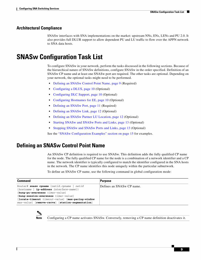
Architectural Compliance
SNASw interfaces with SNA implementations on the market: upstream NNs, ENs, LENs and PU 2.0. It also provides full DLUR support to allow dependent PU and LU traffic to flow over the APPN network to SNA data hosts.
SNASw Configuration Task ListTo configure SNASw in your network, perform the tasks discussed in the following sections. Because of the hierarchical nature of SNASw definitions, configure SNASw in the order specified. Definition of an SNASw CP name and at least one SNASw port are required. The other tasks are optional. Depending on your network, the optional tasks might need to be performed.
• Defining an SNASw Control Point Name, page 9 (Required)
• Configuring a DLUS, page 10 (Optional)
• Configuring DLC Support, page 10 (Optional)
• Configuring Hostnames for EE, page 10 (Optional)
• Defining an SNASw Port, page 11 (Required)
• Defining an SNASw Link, page 12 (Optional)
• Defining an SNASw Partner LU Location, page 12 (Optional)
• Starting SNASw and SNASw Ports and Links, page 13 (Optional)
• Stopping SNASw and SNASw Ports and Links, page 13 (Optional)
See the “SNASw Configuration Examples” section on page 15 for examples.
Defining an SNASw Control Point NameAn SNASw CP definition is required to use SNASw. This definition adds the fully qualified CP name for the node. The fully qualified CP name for the node is a combination of a network identifier and a CP name. The network identifier is typically configured to match the identifier configured in the SNA hosts in the network. The CP name identifies this node uniquely within the particular subnetwork.
To define an SNASw CP name, use the following command in global configuration mode:
Note Configuring a CP name activates SNASw. Conversely, removing a CP name definition deactivates it.
Configuring SNA Switching Services SNASw Configuration Task List
10
Configuring a DLUSIf you plan to provide services to dependent LUs connecting to this SNASw node, you will be using the DLUR functionality within SNASw. SNASw defaults to using its current active upstream Network Node Server (NNS) as the preferred Dependent LU Server (DLUS) for the node. To override this default and explicitly configure the DLUS name, configure the snasw dlus command. In addition, you can configure node-wide defaults for the DLUS and backup DLUS that this node contacts.
To specify DLUR or DLUS services for this CP name, use the following command in SNASw control point configuration mode:
Configuring DLC SupportThere are several ways that SNASw enables connectivity over different interface types. In the simplest cases, using automatically configured real LAN interfaces enables default interface definitions. SNASw is also capable of connecting to virtual interfaces that are not preconfigured on the router.
Virtual Token Ring interfaces are useful for connections to a CIP/CPA in the same router and for connectivity to Frame Relay transport solutions via SRB. Multiple virtual Token Ring interfaces allow SNASw to respond to multiple MAC addresses through the same real router LAN interface. Use the following commands to configure a virtual interface:
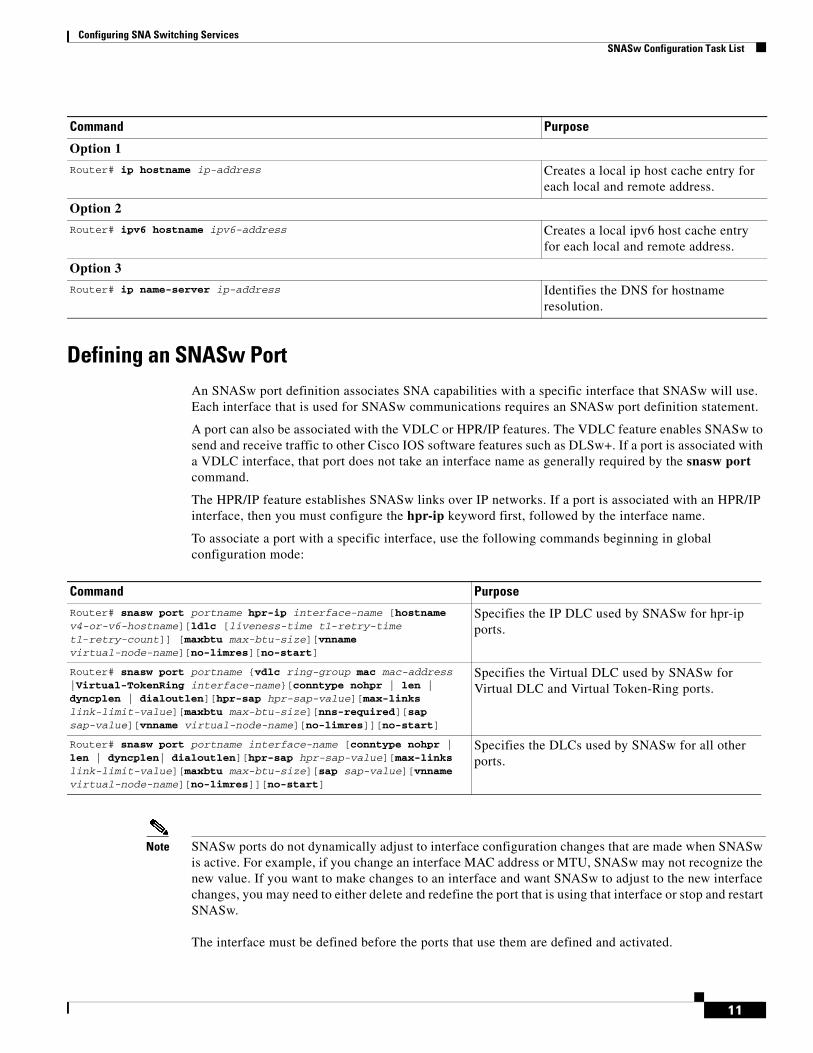
Configuring Hostnames for EEWhen using IPv6 for EE, you must use hostnames rather than explicit IP addresses. When using IPv4 for EE you can optionally use hostnames rather than the explicit IP address and this allows connection network to work through a NAT boundary.
When EE host name support is used, both local and remote IP addresses must be able to be resolved via host names. The host name configuration must be in place before you configure the SNASw port and link or links. Hostnames can be resolved in the local cache (through the ip host or ipv6 host statements) or by configuring a DNS.
To configure hostnames for EE you can use one of the options in global configuration mode from the following table:
Associates a virtual Token Ring interface with a source-route bridge group.
Step 3 Router# source-bridge spanning Indicates this interface should respond to spanning-tree explorers.
Step 4 Router# mac-address mac-address Configures a MAC address on a real or virtual LAN interface.
Configuring SNA Switching Services SNASw Configuration Task List
11
Defining an SNASw PortAn SNASw port definition associates SNA capabilities with a specific interface that SNASw will use. Each interface that is used for SNASw communications requires an SNASw port definition statement.
A port can also be associated with the VDLC or HPR/IP features. The VDLC feature enables SNASw to send and receive traffic to other Cisco IOS software features such as DLSw+. If a port is associated with a VDLC interface, that port does not take an interface name as generally required by the snasw port command.
The HPR/IP feature establishes SNASw links over IP networks. If a port is associated with an HPR/IP interface, then you must configure the hpr-ip keyword first, followed by the interface name.
To associate a port with a specific interface, use the following commands beginning in global configuration mode:
Note SNASw ports do not dynamically adjust to interface configuration changes that are made when SNASw is active. For example, if you change an interface MAC address or MTU, SNASw may not recognize the new value. If you want to make changes to an interface and want SNASw to adjust to the new interface changes, you may need to either delete and redefine the port that is using that interface or stop and restart SNASw.
The interface must be defined before the ports that use them are defined and activated.
Command Purpose
Option 1
Router# ip hostname ip-address Creates a local ip host cache entry for each local and remote address.
Option 2
Router# ipv6 hostname ipv6-address Creates a local ipv6 host cache entry for each local and remote address.
Option 3
Router# ip name-server ip-address Identifies the DNS for hostname resolution.
Specifies the IP DLC used by SNASw for hpr-ip ports.
Router# snasw port portname {vdlc ring-group mac mac-address |Virtual-TokenRing interface-name}[conntype nohpr | len | dyncplen | dialoutlen][hpr-sap hpr-sap-value][max-links link-limit-value][maxbtu max-btu-size][nns-required][sap sap-value][vnname virtual-node-name][no-limres]][no-start]
Specifies the Virtual DLC used by SNASw for Virtual DLC and Virtual Token-Ring ports.
Router# snasw port portname interface-name [conntype nohpr | len | dyncplen| dialoutlen][hpr-sap hpr-sap-value][max-links link-limit-value][maxbtu max-btu-size][sap sap-value][vnname virtual-node-name][no-limres]][no-start]
Specifies the DLCs used by SNASw for all other ports.
Configuring SNA Switching Services SNASw Configuration Task List
12
SNASw does not support EtherChannel interfaces (neither port-channel interfaces nor Fast Ethernet interfaces configured with the channel-group command). Do not try to configure a SNASw port with either of these EtherChannel interface types.
Caution Changing active SNASw interfaces might interrupt SNASw connections.
Defining an SNASw LinkIn many cases, if the destination LU is initiating the connection, a link definition is not necessary. A link definition is built dynamically when the destination LU initiates the connection. Links typically need to be defined for upstream connectivity. Downstream devices initiate connectivity into SNASw; therefore, links should not be defined on SNASw to downstream devices.
In SNASw link configuration, you must associate the link with the SNASw port that it will use. For all traditional links, the snasw link command must be associated with a remote MAC address. The MAC address identifies the partner address to which SNASw attempts to establish a link. For all HPR/IP links, the command is associated with a remote IP address. The IP address identifies the partner address to which SNASw attempts to establish a link.
To define an SNASw logical link, use the following command in global configuration mode:
Defining an SNASw Partner LU LocationThe SNASw directory stores names of resources and their owners. Usually this information is learned dynamically using Locate searches. You might want to manually define the location of specific resources. SNASw is known for its dynamic capabilities, not its need for system definition. For this reason, and for easier management, define location names only when necessary.
When a LEN node connects into an SNASw node, SNASw dynamically learns the CP name of the LEN and places it in its directory. In addition, SNASw dynamically learns the LU names of all LUs on the LEN that initiate independent sessions. Only define the location when an ILU on a LEN device is not sharing the node's CP name and does not initiate the first session. In all other cases the LU's location will be learned dynamically.
The directory entry is created the next time the LEN node connects in. If there is already a link to the LEN node active and you add a new snasw location statement, it will not take effect until the next time the LEN CP connects in.
To define a resource location, use the following command in global configuration mode:
Router# snasw location resource-name owning-cp cpname Configures the location of a resource.
Configuring SNA Switching Services Verifying SNASw
13
Note You must configure an owning CP for each partner LU configured. The owning CP is the CP name for the LEN node on which the partner resource resides. Location definitions are never required for resources located on APPN ENs or NNs.
Starting SNASw and SNASw Ports and LinksUnless otherwise defined with the nostart operand, SNASw starts automatically when a CP name is configured, and SNASw ports and links are also automatically started once they are configured. If stopped, they can be restarted using one of the following privileged EXEC commands, as needed:
Stopping SNASw and SNASw Ports and LinksUnless otherwise defined with the nostart operand, SNASw and SNASw port and link definitions are started automatically when SNASw starts. To stop SNASw or to stop SNASw ports and links when making configuration changes or when resetting the ports or links, use one of the following commands in privileged EXEC mode, as needed:
Note Removing a CP name definition stops SNASw.
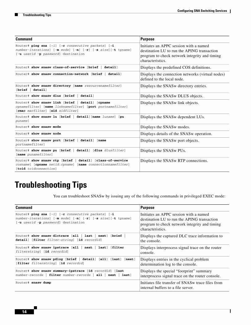
Verifying SNASwTo verify that you have connectivity between SNASw and other nodes supporting APINGD transaction program, issue the ping sna command. To start an independent LU-LU session and send simple APINGD test data traffic, also issue the ping sna command.
Monitoring and Maintaining SNASwYou can monitor the status and configuration of SNASw by issuing any of the following commands in privileged EXEC mode:
Command Purpose
Router# snasw start Starts SNASw.
Router# snasw start link linkname Activates the specified SNASw link.
Router# snasw start port portname Activates the specified SNASw port.
Command Purpose
Router# snasw stop Deactivates SNASw.
Router# snasw stop link linkname Deactivates the specified SNASw link.
Router# snasw stop port portname Deactivates the specified SNASw port.
Configuring SNA Switching Services Troubleshooting Tips
14
Troubleshooting TipsYou can troubleshoot SNASw by issuing any of the following commands in privileged EXEC mode:
Displays entries in the cyclical problem determination log to the console.
Router# show snasw summary-ipstrace [id recordid] [last number-records | filter number-records | all | next | last]
Displays the special “footprint” summary interprocess signal trace on the router console.
Router# snasw dump Initiates file transfer of SNASw trace files from internal buffers to a file server.
Configuring SNA Switching Services SNASw Configuration Examples
15
You can also troubleshoot SNASw by issuing any of the following commands in global configuration mode:
SNASw Configuration ExamplesThis section provides the following configuration examples:
• SNASw over Token Ring without HPR Configuration Example, page 16
• SNASw over Token Ring with HPR Configuration Example, page 17
• SNASw Connecting to a CIP over Virtual Token Ring with SRB Configuration Example, page 18
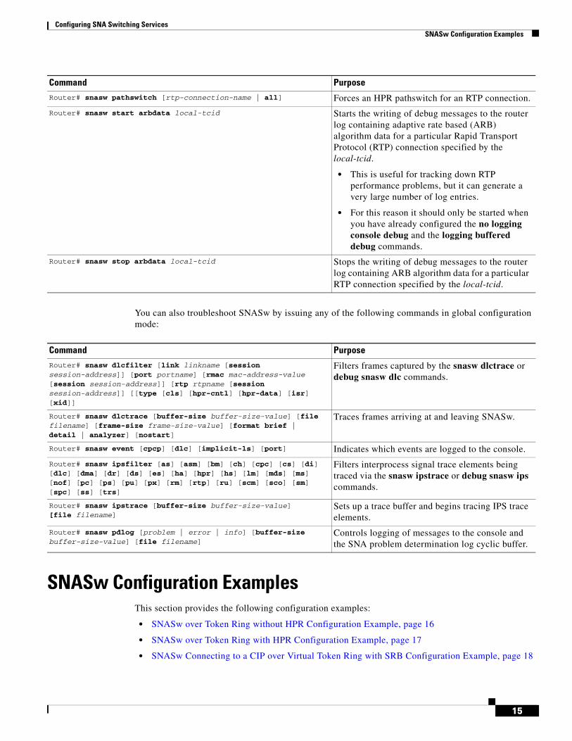
Router# snasw pathswitch [rtp-connection-name | all] Forces an HPR pathswitch for an RTP connection.
Router# snasw start arbdata local-tcid Starts the writing of debug messages to the router log containing adaptive rate based (ARB) algorithm data for a particular Rapid Transport Protocol (RTP) connection specified by the local-tcid.
• This is useful for tracking down RTP performance problems, but it can generate a very large number of log entries.
• For this reason it should only be started when you have already configured the no logging console debug and the logging buffered debug commands.
Router# snasw stop arbdata local-tcid Stops the writing of debug messages to the router log containing ARB algorithm data for a particular RTP connection specified by the local-tcid.
Controls logging of messages to the console and the SNA problem determination log cyclic buffer.
Configuring SNA Switching Services SNASw Configuration Examples
16
• SNASw over HPR/IP Configuration Example, page 20
• SNASw Using Local Switching with QLLC Configuration Example, page 21
• SNASw Using Local Switching with SDLC Configuration Example, page 22
• SNASw with Ethernet LAN Emulation over ATM Configuration Example, page 23
• SNASw with SRB Frame Relay (Frame Relay BAN Support) Configuration Example, page 24
• SNASw with FRAS Host (Downstream Frame Relay BNN Support) Configuration Example, page 26
• SNASw vs APPN Connecting VTAM to the CIP Using CMPC Configuration Example, page 27
• SNASw vs APPN Connecting to VTAM on a Remote Router with DLUR Using CMPC, page 30
• SNASw Dial-out to a DLUR Downstream Configuration Example, page 34
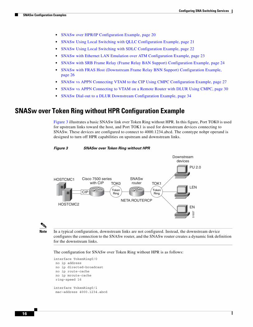
SNASw over Token Ring without HPR Configuration ExampleFigure 3 illustrates a basic SNASw link over Token Ring without HPR. In this figure, Port TOK0 is used for upstream links toward the host, and Port TOK1 is used for downstream devices connecting to SNASw. These devices are configured to connect to 4000.1234.abcd. The conntype nohpr operand is designed to turn off HPR capabilities on upstream and downstream links.
Figure 3 SNASw over Token Ring without HPR
Note In a typical configuration, downstream links are not configured. Instead, the downstream device configures the connection to the SNASw router, and the SNASw router creates a dynamic link definition for the downstream links.
The configuration for SNASw over Token Ring without HPR is as follows:
interface TokenRing0/0no ip addressno ip directed-broadcastno ip route-cacheno ip mroute-cachering-speed 16
interface TokenRing0/1mac-address 4000.1234.abcd
CIP
Cisco 7500 serieswith CIP
SNASwrouter
NETA.ROUTERCP
TOK0 TOK1
TokenRing
TokenRing
Downstreamdevices
PU 2.0
LEN
EN
5193
7
HOSTCMC2
HOSTCMC1
Configuring SNA Switching Services SNASw Configuration Examples
17
no ip addressno ip directed-broadcastno ip route-cacheno ip mroute-cache
ring-speed 16
snasw rtp pathswitch-timers 160 80 40 20 snasw cpname NETA.ROUTERCPsnasw dlus NETA.HOSTCMC1 backup NETA.HOSTCMC2snasw port TOK0 TokenRing0/0 conntype nohpr snasw port TOK1 TokenRing0/1 conntype nohprsnasw link HOSTCMC1 port TOK0 rmac 4000.aaaa.ccccsnasw link HOSTCMC2 port TOK0 rmac 4000.aaaa.dddd
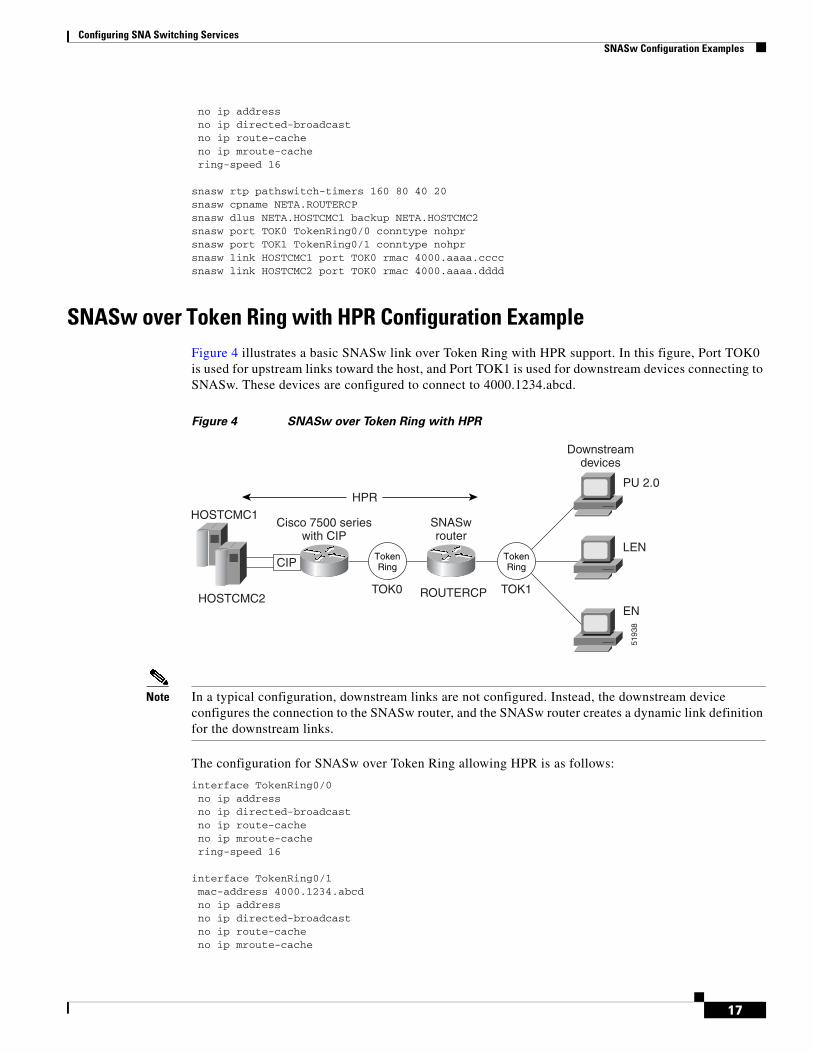
SNASw over Token Ring with HPR Configuration ExampleFigure 4 illustrates a basic SNASw link over Token Ring with HPR support. In this figure, Port TOK0 is used for upstream links toward the host, and Port TOK1 is used for downstream devices connecting to SNASw. These devices are configured to connect to 4000.1234.abcd.
Figure 4 SNASw over Token Ring with HPR
Note In a typical configuration, downstream links are not configured. Instead, the downstream device configures the connection to the SNASw router, and the SNASw router creates a dynamic link definition for the downstream links.
The configuration for SNASw over Token Ring allowing HPR is as follows:
interface TokenRing0/0no ip addressno ip directed-broadcastno ip route-cacheno ip mroute-cachering-speed 16
interface TokenRing0/1mac-address 4000.1234.abcdno ip addressno ip directed-broadcastno ip route-cacheno ip mroute-cache
CIP
Cisco 7500 serieswith CIP
SNASwrouter
TOK0 TOK1
TokenRing
TokenRing
Downstreamdevices
PU 2.0
LEN
EN
5193
8
HPR
HOSTCMC1
HOSTCMC2 ROUTERCP
Configuring SNA Switching Services SNASw Configuration Examples
18
ring-speed 16
snasw cpname NETA.ROUTERCPsnasw dlus NETA.HOSTCMC1 backup NETA.HOSTCMC2snasw port TOK0 TokenRing0/0 snasw port TOK1 TokenRing0/1 snasw link HOSTCMC1 port TOK0 rmac 4000.aaaa.ccccsnasw link HOSTCMC2 port TOK0 rmac 4000.aaaa.dddd
SNASw Connecting to a CIP over Virtual Token Ring with SRB Configuration Example
In Figure 5, SNASw co-exists with CSNA CIP channel support in the same router. Two adapters are opened on the CIP, one from HOSTCMC1 on adapter 1 and one from HOSTCMC2 on adapter 2. SNASw is configured to connect these two hosts through port CIP via the SRB infrastructure. In addition, SNASw has two ports configured for downstream devices. Using this configuration, SNASw responds to downstream clients connecting to 4000.1234.1088 and 4000.1234.1089 through a single Token Ring interface (Token Ring 0/0). The router’s hostname is used to derive an SNASw CP name, which is NETA.SNASWRT1.
Figure 5 SNASw Connecting to a CIP over Virtual Token Ring with SRB
Note In a typical configuration, downstream links are not configured. Instead, the downstream device configures the connection to the SNASw router, and the SNASw router creates a dynamic link definition for the downstream links.
The configuration for SNASw connecting to a CIP over virtual Token Ring with SRB is as follows:
Configuring SNA Switching Services SNASw Configuration Examples
19
no ip addressno keepalivelan TokenRing 0source-bridge 101 1 100adapter 0 4000.0000.ccccadapter 1 4000.0000.dddd
!interface TokenRing0/0no ip addressring-speed 16source-bridge 201 1 200source-bridge spanning
!interface Virtual-TokenRing0no ip addressno ip directed-broadcastring-speed 16source-bridge 102 1 100source-bridge spanning
!interface Virtual-TokenRing1mac-address 4000.1234.1088no ip addressno ip directed-broadcastring-speed 16source-bridge 202 1 200source-bridge spanning
!interface Virtual-TokenRing2mac-address 4000.1234.1089no ip addressno ip directed-broadcastring-speed 16source-bridge 203 1 200
!snasw cpname NETA hostnamesnasw dlus NETA.HOSTCMC1 backup NETA.HOSTCMC2snasw port CIP Virtual-TokenRing0snasw port DOWNSTRM Virtual-TokenRing1 conntype no-hprsnasw port DOWNSTRM Virtual-TokenRing2 conntype no-hprsnasw link HOSTCMC1 port CIP rmac 4000.0000.ccccsnasw link HOSTCMC2 port CIP rmac 4000.0000.dddd
Configuring SNA Switching Services SNASw Configuration Examples
20
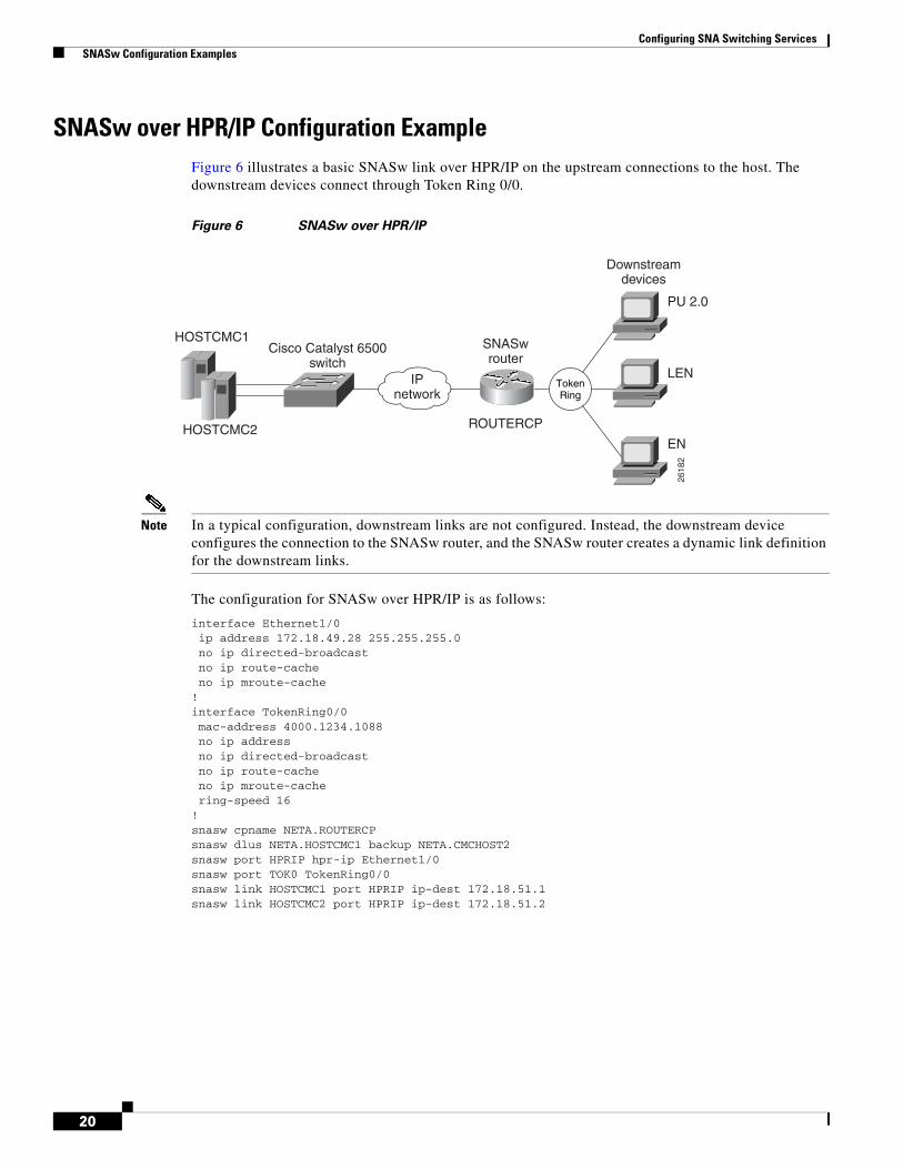
SNASw over HPR/IP Configuration ExampleFigure 6 illustrates a basic SNASw link over HPR/IP on the upstream connections to the host. The downstream devices connect through Token Ring 0/0.
Figure 6 SNASw over HPR/IP
Note In a typical configuration, downstream links are not configured. Instead, the downstream device configures the connection to the SNASw router, and the SNASw router creates a dynamic link definition for the downstream links.
The configuration for SNASw over HPR/IP is as follows:
interface Ethernet1/0ip address 172.18.49.28 255.255.255.0no ip directed-broadcastno ip route-cacheno ip mroute-cache
!interface TokenRing0/0mac-address 4000.1234.1088no ip addressno ip directed-broadcastno ip route-cacheno ip mroute-cachering-speed 16
!snasw cpname NETA.ROUTERCPsnasw dlus NETA.HOSTCMC1 backup NETA.CMCHOST2snasw port HPRIP hpr-ip Ethernet1/0 snasw port TOK0 TokenRing0/0snasw link HOSTCMC1 port HPRIP ip-dest 172.18.51.1snasw link HOSTCMC2 port HPRIP ip-dest 172.18.51.2
Cisco Catalyst 6500switch
HOSTCMC1
HOSTCMC2
IPnetwork
SNASwrouter
ROUTERCP
Downstreamdevices
PU 2.0
LEN
EN
2618
2
TokenRing
Configuring SNA Switching Services SNASw Configuration Examples
21
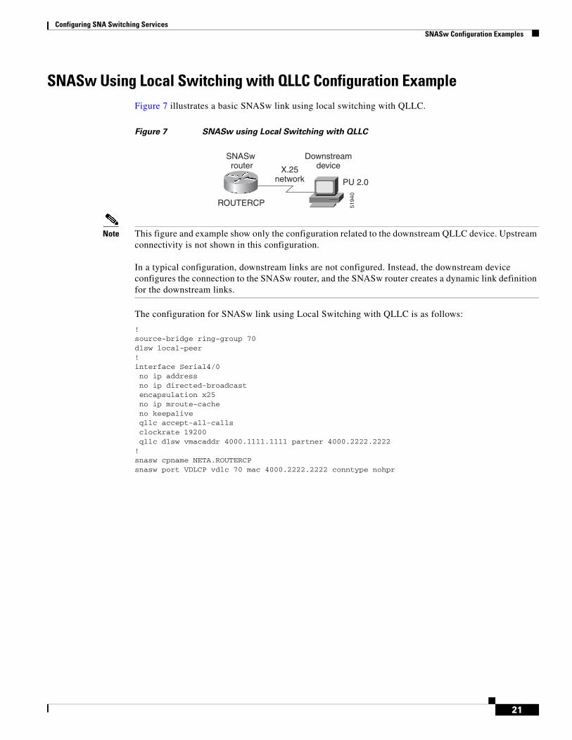
SNASw Using Local Switching with QLLC Configuration ExampleFigure 7 illustrates a basic SNASw link using local switching with QLLC.
Figure 7 SNASw using Local Switching with QLLC
Note This figure and example show only the configuration related to the downstream QLLC device. Upstream connectivity is not shown in this configuration.
In a typical configuration, downstream links are not configured. Instead, the downstream device configures the connection to the SNASw router, and the SNASw router creates a dynamic link definition for the downstream links.
The configuration for SNASw link using Local Switching with QLLC is as follows:
!source-bridge ring-group 70dlsw local-peer!interface Serial4/0no ip addressno ip directed-broadcastencapsulation x25no ip mroute-cacheno keepaliveqllc accept-all-callsclockrate 19200qllc dlsw vmacaddr 4000.1111.1111 partner 4000.2222.2222
!snasw cpname NETA.ROUTERCPsnasw port VDLCP vdlc 70 mac 4000.2222.2222 conntype nohpr
X.25network
SNASw router
ROUTERCP
Downstreamdevice
5194
0
PU 2.0
Configuring SNA Switching Services SNASw Configuration Examples
22
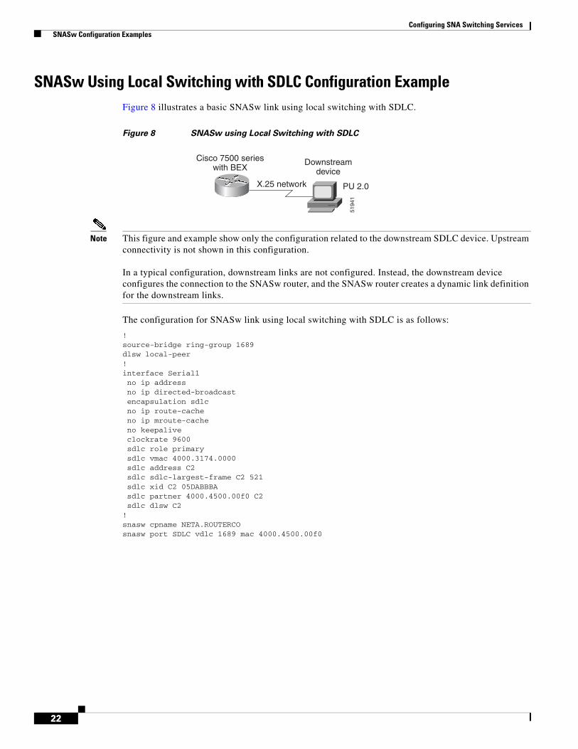
SNASw Using Local Switching with SDLC Configuration ExampleFigure 8 illustrates a basic SNASw link using local switching with SDLC.
Figure 8 SNASw using Local Switching with SDLC
Note This figure and example show only the configuration related to the downstream SDLC device. Upstream connectivity is not shown in this configuration.
In a typical configuration, downstream links are not configured. Instead, the downstream device configures the connection to the SNASw router, and the SNASw router creates a dynamic link definition for the downstream links.
The configuration for SNASw link using local switching with SDLC is as follows:
!source-bridge ring-group 1689dlsw local-peer!interface Serial1no ip addressno ip directed-broadcastencapsulation sdlcno ip route-cacheno ip mroute-cacheno keepaliveclockrate 9600sdlc role primarysdlc vmac 4000.3174.0000sdlc address C2sdlc sdlc-largest-frame C2 521sdlc xid C2 05DABBBAsdlc partner 4000.4500.00f0 C2sdlc dlsw C2
!snasw cpname NETA.ROUTERCOsnasw port SDLC vdlc 1689 mac 4000.4500.00f0
X.25 network
Cisco 7500 serieswith BEX
Downstreamdevice
5194
1
PU 2.0
Configuring SNA Switching Services SNASw Configuration Examples
23
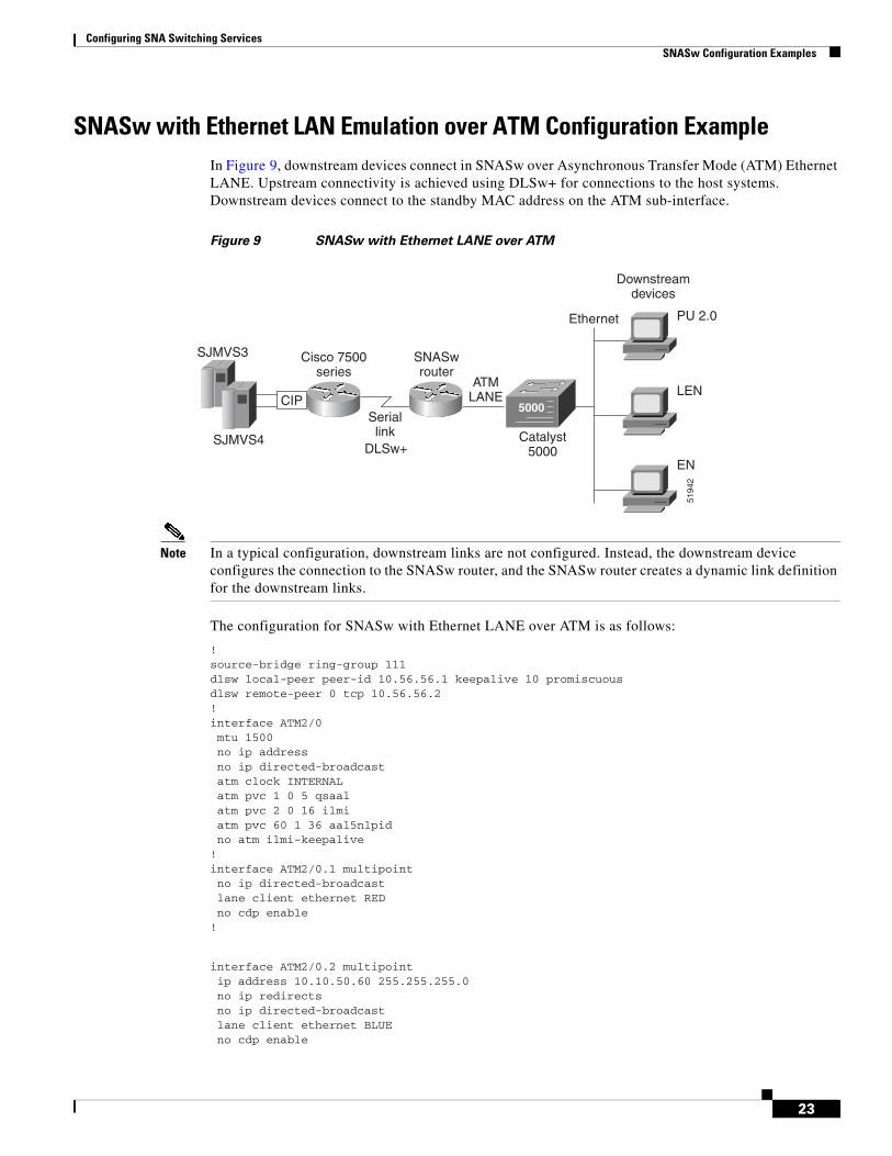
SNASw with Ethernet LAN Emulation over ATM Configuration ExampleIn Figure 9, downstream devices connect in SNASw over Asynchronous Transfer Mode (ATM) Ethernet LANE. Upstream connectivity is achieved using DLSw+ for connections to the host systems. Downstream devices connect to the standby MAC address on the ATM sub-interface.
Figure 9 SNASw with Ethernet LANE over ATM
Note In a typical configuration, downstream links are not configured. Instead, the downstream device configures the connection to the SNASw router, and the SNASw router creates a dynamic link definition for the downstream links.
The configuration for SNASw with Ethernet LANE over ATM is as follows:
!snasw cpname NETA.ROUTERCPsnasw dlus NETA.SJMVS3 backup NETA.HOSTCMC2snasw port ATM202 ATM2/0.2 conntype nohprsnasw port DLSWP vdlc 111 mac 4000.0189.0016 conntype nohprsnasw link HOSTCMC1 port DLSWP rmac 4000.aaaa.ccccsnasw link HOSTCMC2 port DLSWP rmac 4000.aaaa.dddd!
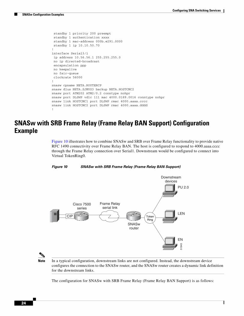
SNASw with SRB Frame Relay (Frame Relay BAN Support) Configuration Example
Figure 10 illustrates how to combine SNASw and SRB over Frame Relay functionality to provide native RFC 1490 connectivity over Frame Relay BAN. The host is configured to respond to 4000.aaaa.cccc through the Frame Relay connection over Serial1. Downstream would be configured to connect into Virtual TokenRing0.
Figure 10 SNASw with SRB Frame Relay (Frame Relay BAN Support)
Note In a typical configuration, downstream links are not configured. Instead, the downstream device configures the connection to the SNASw router, and the SNASw router creates a dynamic link definition for the downstream links.
The configuration for SNASw with SRB Frame Relay (Frame Relay BAN Support) is as follows:
CIP
Frame Relayserial link
Cisco 7500series
SNASwrouter
Downstreamdevices
PU 2.0
LEN
EN
5194
3
TokenRing
Configuring SNA Switching Services SNASw Configuration Examples
25
source-bridge ring-group 100source-bridge ring-group 200!interface TokenRing0no ip addressno ip directed-broadcastring-speed 16source-bridge 202 1 200!interface Virtual-TokenRing0mac-address 4000.1234.1001no ip addressno ip directed-broadcastring-speed 16source-bridge 201 1 200!interface Serial1 encapsulation frame-relay
Note This figure and example show only the configuration related to downstream Frame Relay BNN Support. Upstream connectivity is not shown in this configuration segment.
In a typical configuration, downstream links are not configured. Instead, the downstream device configures the connection to the SNASw router, and the SNASw router creates a dynamic link definition for the downstream links.
The configuration SNASw with FRAS Host (Downstream Frame Relay BNN Support) is as follows:
Configuring SNA Switching Services SNASw Configuration Examples
27
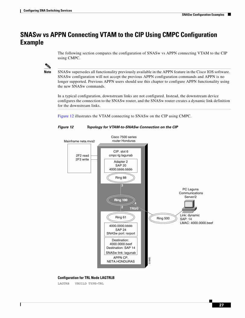
SNASw vs APPN Connecting VTAM to the CIP Using CMPC Configuration Example
The following section compares the configuration of SNASw vs APPN connecting VTAM to the CIP using CMPC.
Note SNASw supersedes all functionality previously available in the APPN feature in the Cisco IOS software. SNASw configuration will not accept the previous APPN configuration commands and APPN is no longer supported. Previous APPN users should use this chapter to configure APPN functionality using the new SNASw commands.
In a typical configuration, downstream links are not configured. Instead, the downstream device configures the connection to the SNASw router, and the SNASw router creates a dynamic link definition for the downstream links.
Figure 12 illustrates the VTAM connecting to SNASw on the CIP using CMPC.
Figure 12 Topology for VTAM-to-SNASw Connection on the CIP
Configuration for TRL Node LAGTRLBLAGTRB VBUILD TYPE=TRL
Configuring SNA Switching Services SNASw Configuration Examples
28
LAGTRLB TRLE LNCTL=MPC,MAXBFRU=8,REPLYTO=3.0, X READ=(2F2), X WRITE=(2F3)
Local SNA Major Node LAGLNBLAGNNB VBUILD TYPE=LOCAL LAGPUB PU TRLE=LAGTRLB, X ISTATUS=ACTIVE, X XID=YES,CONNTYPE=APPN,CPCP=YES
Honduras Router source-bridge ring-group 100!interface Channel6/1 no ip address no keepalive cmpc C020 F2 LAGUNAB READ cmpc C020 F3 LAGUNAB WRITE!interface Channel6/2 no ip address no keepalive lan TokenRing 0
source-bridge 88 3 100adapter 2 4000.bbbb.bbbb
lan TokenRing 2 tg LAGUNAB llc token-adapter 2 20 rmac 4000.0000.bbbb rsap 24!!interface Virtual-TokenRing0 mac-address 4000.0000.bbbb no ip address no ip directed-broadcast ring-speed 16 source-bridge 61 2 100!snasw cpname NETA.HONDURASsnasw port VTOK Virtual-TokenRing0snasw link MVS2D port VTOK rmac 4000.bbbb.bbbb
Configuring SNA Switching Services SNASw Configuration Examples
29
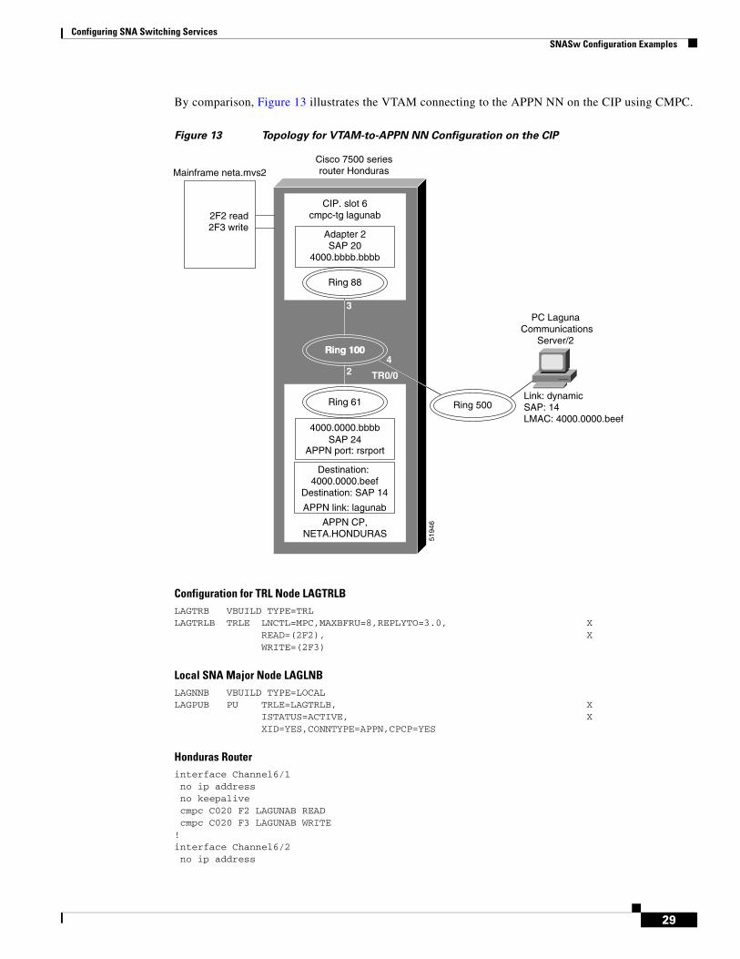
By comparison, Figure 13 illustrates the VTAM connecting to the APPN NN on the CIP using CMPC.
Figure 13 Topology for VTAM-to-APPN NN Configuration on the CIP
Configuration for TRL Node LAGTRLBLAGTRB VBUILD TYPE=TRL LAGTRLB TRLE LNCTL=MPC,MAXBFRU=8,REPLYTO=3.0, X READ=(2F2), X WRITE=(2F3)
Local SNA Major Node LAGLNBLAGNNB VBUILD TYPE=LOCAL LAGPUB PU TRLE=LAGTRLB, X ISTATUS=ACTIVE, X XID=YES,CONNTYPE=APPN,CPCP=YES
Honduras Router interface Channel6/1 no ip address no keepalive cmpc C020 F2 LAGUNAB READ cmpc C020 F3 LAGUNAB WRITE!interface Channel6/2 no ip address
port RSRBPORTlan-dest-address 4000.0000.beef 14complete
router eigrp 109network 172.18.0.0
SNASw vs APPN Connecting to VTAM on a Remote Router with DLUR Using CMPC
The following section compares the configurations of SNASw vs APPN while connecting to VTAM on a remote router with DLUR using CMPC.
In the example shown in Figure 14 and Figure 15, DLUS is running on the MVS host. DLUR is running on a remote Cisco 4000 router. The connection from MPC to the APPN stack on the Cisco 4000 is via LLC2. There is no NN on the Cisco 7500. The PC is running Communications Server/2.
Note SNASw supersedes all functionality previously available in the APPN feature in the Cisco IOS software. SNASw configuration will not accept the previous APPN configuration commands and APPN is no longer supported. Previous APPN users should use this chapter to configure APPN functionality using the new SNASw commands.
In a typical configuration, downstream links are not configured. Instead, the downstream device configures the connection to the SNASw router, and the SNASw router creates a dynamic link definition for the downstream links.
Configuring SNA Switching Services SNASw Configuration Examples
31
Figure 14 illustrates a DLUS-to-DLUR configuration using SNASw.
Figure 14 Topology for VTAM-to-SNASw on a Remote Router with DLUR Connection
mvs2trldMVS2TRD VBUILD TYPE=TRL MVS2TRLD TRLE LNCTL=MPC,MAXBFRU=8,REPLYTO=3.0, X READ=(2F7), X WRITE=(2F6)
mvs2lndMVS2NND VBUILD TYPE=LOCAL MVS2PUD PU TRLE=MVS2TRLD, X ISTATUS=ACTIVE, X XID=YES,CONNTYPE=APPN,CPCP=YES
Additional Configuration for Router Hondurasinterface Channel6/1 cmpc C020 F6 CONFIGD WRITE cmpc C020 F7 CONFIGD READ!interface Channel6/2 lan TokenRing 0
Configuring SNA Switching Services SNASw Configuration Examples
32
Router Dustinsource-bridge ring-group 84interface Ethernet0 ip address 172.18.3.36 255.255.255.0 media-type 10BaseT!interface TokenRing0 no ip address ring-speed 16 source-bridge 500 2 84!interface Virtual-TokenRing0 mac-address 4000.0000.dddd no ip address no ip directed-broadcast ring-speed 16 source-bridge 94 5 84!snasw cpname NETA.DUSTINsnasw dlus NETA.MVS2snasw port VTOK Virtual-TokenRing0snasw link MVS2D port VTOK rmace 4000.dddd.dddd
Configuring SNA Switching Services SNASw Configuration Examples
33
By comparison, Figure 15 illustrates a DLUS-to-DLUR configuration using APPN.
Figure 15 Topology for VTAM-to-APPN NN on a Remote Router with DLUR Connection
mvs2trldMVS2TRD VBUILD TYPE=TRL MVS2TRLD TRLE LNCTL=MPC,MAXBFRU=8,REPLYTO=3.0, X READ=(2F7), X WRITE=(2F6)
mvs2lndMVS2NND VBUILD TYPE=LOCAL MVS2PUD PU TRLE=MVS2TRLD, X ISTATUS=ACTIVE, X XID=YES,CONNTYPE=APPN,CPCP=YES
port RSRBPORTlan-dest-address 4000.0000.beef 14complete
!appn link-station MVS2D
port RSRBPORTlan-dest-address 4000.dddd.dddd 40
complete
SNASw Dial-out to a DLUR Downstream Configuration ExampleSNASw downstream connections are usually initiated by downstream devices. Alternatively, VTAM has a“dial-out” function where the downstream connectivity information is configured at VTAM, and passed down to SNASw to initiate the connection from SNASw to the downstream device. This section describes the SNASw and VTAM changes that are needed for this configuration.
The following example shows how to configure SNASw on SNA7200:
Configuring SNA Switching Services SNASw Configuration Examples
35
ip address 172.18.3.36 255.255.255.0!interface TokenRing0 no ip address ring-speed 16 source-bridge 500 2 84!snasw cpname NETA.SNA7200snasw dlus NETA.MVSD snasw port FA01EE hpr-ip FastEthernet0/0snasw port TOK0 TokenRing4/0 conntype dialoutlen snasw link MVSDIP port FA01EE ip-dest 172.18.1.41
Note “conntype dialoutlen” on the downstream port definition (TOK0) is needed only when LU 6.2 communications is used by the downstream device.
The VTAM switched major node syntax is as follows:
PATH DLURNAME=<NETID.CP name of SNASw router>, DLCADDR=(1,C,TR), <specifies token ring address format> DLCADDR=(2,X,<name of downstream port in SNASw config, expressed in hex EBCDIC format>), -OR - DLCADDR=(2,C,<name of downstream port in SNASw config expressed in character format>), DLCADDR=(3,X, <sap value, usually 04>), DLCADDR=(4,X,<mac address of the downstream device in token ring format>)
The following example shows how to configure VTAM for a downstream dial out PU where the downstream device on a Token Ring has the MAC address of 1000.5a6d.32ab:
In Cisco IOS Release 12.3(14) and earlier, you must use hexadecimal EBCDIC format for DLCADDR parameter 2, as such:
EXPUPATH PATH DLURNAME=NETA.SNA7200, DLCADDR=(1,C,TR), DLCADDR=(2,X,E3D6D2F0), DLCADDR=(3,X,04), DLCADDR=(4,X,10005A6D32AB)Cisco and the Cisco Logo are trademarks of Cisco Systems, Inc. and/or its affiliates in the U.S. and other countries. A listing of Cisco's trademarks can be found at www.cisco.com/go/trademarks. Third party trademarks mentioned are the property of their respective owners. The use of the word partner does not imply a partnership relationship between Cisco and any other company. (1005R)
Any Internet Protocol (IP) addresses used in this document are not intended to be actual addresses. Any examples, command display output, and figures included in the document are shown for illustrative purposes only. Any use of actual IP addresses in illustrative content is unintentional and coincidental.