Configuring the Cisco Wireless Controller Network Module on a Cisco Router, Cisco IOS Release 12.4(15)T
The Cisco wireless LAN (WLAN) controller network module (WLCM) is designed to provide small- and medium-sized businesses (SMBs) and enterprise branch office customers 802.11 wireless networking solutions for Cisco 2800 series and Cisco 3800 series Integrated Services Routers (ISRs) and Cisco 3700 series routers. The Cisco WLCM operating system enables Cisco ISRs and Cisco 3700 series routers to manage up to 8 or 12 WLAN access points (APs) and simplifies deploying and managing wireless LANs. The operating system manages all data client, communications, and system administration functions, performs radio resource management (RRM) functions, manages system-wide mobility policies using the operating system security (OSS), and coordinates all security functions using the OSS framework. The Cisco WLCM works in conjunction with Cisco Aironet lightweight access points, the Cisco Wireless Control System (WCS), and the Cisco Wireless Location Appliance (WLA) to support wireless data, voice, and video applications.
For information about the Cisco Wireless LAN controller module NM-AIR-WLC6 solution, see the Cisco Network Modules Hardware Installation Guide at the following URL:
Configuring the Cisco Wireless Controller Network Module on a Cisco Router, Cisco IOS Release 12.4(15)T Obtaining Documentation, Obtaining Support, and Security Guidelines
Obtaining Documentation, Obtaining Support, and Security Guidelines
For information on obtaining documentation, obtaining support, providing documentation feedback, security guidelines, and also recommended aliases and general Cisco documents, see the monthly What’s New in Cisco Product Documentation, which also lists all new and revised Cisco technical documentation, at:
Contents• Prerequisites for Configuring the Cisco WLCM on a Cisco Router, page 2
• Restrictions for Configuring the Cisco WLCM on a Cisco Router, page 2
• Information About the Cisco WLCM on a Cisco Router, page 3
• How to Configure the Cisco WLCM, page 6
• Additional References, page 48
• Commands at a Glance, page 50
Prerequisites for Configuring the Cisco WLCM on a Cisco RouterThe Cisco WLCM operating system on the Cisco WLCM must be compatible with the Cisco IOS software release and feature set on the router.
Use the following commands to view the Cisco IOS version on the router and to view the operating system version on the WLCM.
• To view the Cisco IOS software release and feature set, enter the show version command in privileged EXEC mode on the router.
• To view the Cisco WLCM OS version, enter the show sysinfo: command at the WLCM prompt.
Restrictions for Configuring the Cisco WLCM on a Cisco RouterThe WLCM does not manage the integrated access points (HWIC-AP modules) on Cisco ISRs.
Configuring the Cisco Wireless Controller Network Module on a Cisco Router, Cisco IOS Release 12.4(15)T Information About the Cisco WLCM on a Cisco Router
Information About the Cisco WLCM on a Cisco RouterThe Cisco WLCM is supported on the following router platforms:
• Cisco 3725 and 3745 routers
For information about Cisco 3700 series routers wireless support, see the following URL:
Cisco WLCMs ship with a boot loader and a 512-MB CompactFlash memory card. The CompactFlash memory card contains the boot loader, Linux kernel, Cisco WLCM and access points executable file, emergency upgrade software, and Cisco WLCM configuration.
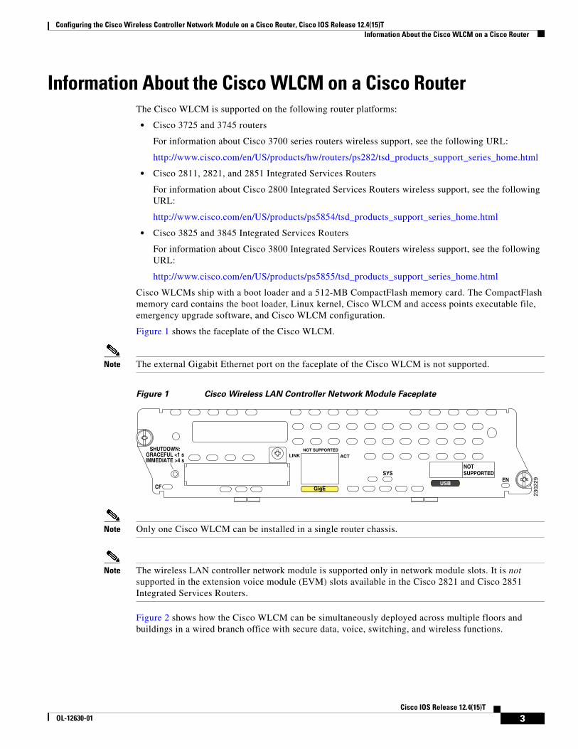
Figure 1 shows the faceplate of the Cisco WLCM.
Note The external Gigabit Ethernet port on the faceplate of the Cisco WLCM is not supported.
Figure 1 Cisco Wireless LAN Controller Network Module Faceplate
Note Only one Cisco WLCM can be installed in a single router chassis.
Note The wireless LAN controller network module is supported only in network module slots. It is not supported in the extension voice module (EVM) slots available in the Cisco 2821 and Cisco 2851 Integrated Services Routers.
Figure 2 shows how the Cisco WLCM can be simultaneously deployed across multiple floors and buildings in a wired branch office with secure data, voice, switching, and wireless functions.
Configuring the Cisco Wireless Controller Network Module on a Cisco Router, Cisco IOS Release 12.4(15)T Information About the Cisco WLCM on a Cisco Router
Figure 2 Cisco WLCM Deployment for Converged Wireless with Secure Data, Voice, Switching,
and Wireless Functions
The Cisco Wireless Control System (WCS) allows users to design, control, and monitor enterprise wireless networks from a centralized location. The Cisco WCS is an optional network component that works in conjunction with Cisco APs and Cisco WLCMs.
The Cisco 2700 series location appliance is another optional network component that enhances the high-accuracy, built-in, Cisco WCS location-tracking abilities by computing, collecting, and storing historical location data. This data can be displayed in the Cisco WCS. The location appliance acts as a server to one or more Cisco WCS servers; the location appliance collects, stores, and passes on data from its associated controllers. For complete information about managing the Cisco WLAN location appliance, see the following URL:
Power over EthernetPower over Ethernet (PoE) is supported on Cisco ISR routers. When using PoE, the installer runs a single CAT-5 cable from each access point to PoE-equipped network elements, such as a PoE-compliant Cisco EtherSwitch service module on the integrated services router or a Cisco Catalyst 3750 switch with PoE. When the PoE equipment determines that the access point is PoE-enabled, it sends -48 VDC over the unused pairs in the Ethernet cable to power the access point.
Connecting Access PointsAccess points can be connected to a separate switch or to a Cisco EtherSwitch service module on Cisco ISRs. The Cisco ISR family supports a range of integrated Cisco EtherSwitch service modules with 4 to 48 ports supporting PoE.
Note Only Cisco EtherSwitch service modules support PoE. Cisco Ethernet switch network modules (NM-16ESW and NMD-36ESW) do not support PoE.
Configuring the Cisco Wireless Controller Network Module on a Cisco Router, Cisco IOS Release 12.4(15)T Information About the Cisco WLCM on a Cisco Router
Operating System User InterfacesThe Cisco WLCM and its associated Cisco access points can be concurrently managed by these operating system user interfaces:
• Command line interface (CLI)—The CLI is a full-featured but simple text-based, tree-structured interface that allows up to five users with Telnet-capable terminal emulators to simultaneously manage all aspects of the Cisco WLCM and associated Cisco access points. You can locally or remotely configure, monitor, and control individual Cisco WLCMs.
For more information about the CLI and a complete list of features available on the Cisco WLCM, see the Cisco Wireless LAN Solution Product Guide at the following URL:
• Cisco WLCM web GUI—The web user interface is built into each Cisco wireless LAN controller. The web user interface allows up to five users to simultaneously browse the built-in Cisco wireless LAN controller http: or https: (http + SSL) web server, configure parameters, and monitor operational status for the Cisco wireless LAN controller and its associated access points.
Note We recommend that you enable the https: interfaces and disable the http: interfaces to ensure stronger security for your Cisco WLAN solution.
Because the web user interface works with one Cisco wireless LAN controller at a time, the web user interface is especially useful when you wish to configure or monitor a single Cisco wireless LAN controller and its associated access points that support Lightweight Access Point Protocol (LWAPP). The web GUI is supported on Internet Explorer, version 6.0 Standard and Enterprise Editions (SP1) or later.
For complete information about the GUI, see the Cisco Wireless LAN Solution Product Guide at the following URL:
• Cisco WCS—The Cisco WCS is the Cisco wireless LAN solution network management tool that adds to the capabilities of the web user interface and the CLI, moving from individual controllers to a network of controllers. The Cisco WCS runs on Windows 2000, Windows 2003, and Red Hat Enterprise Linux ES servers.
The Cisco WCS includes the same configuration, performance monitoring, security, fault management, and accounting options that are used at the Cisco wireless LAN controller level, but adds a graphical view of multiple controllers and managed access points.
For complete information about the Cisco WCS, see the Cisco Wireless LAN Solution Product Guide at the following URL:
The Cisco WLCM, together with Cisco ISRs, supports IPSec security for wireless clients that terminate on Cisco ISRs through the use of a VPN pass-through on the Cisco WLCM.
Configuring the Cisco Wireless Controller Network Module on a Cisco Router, Cisco IOS Release 12.4(15)T How to Configure the Cisco WLCM
How to Configure the Cisco WLCMThis section contains the following procedures:
• Accessing the CLI Through a Console Connection or Through Telnet, page 7
• Understanding Interfaces on the Cisco WLCM, page 7
• Using Interface Configuration Mode, page 8
• Configuring the Cisco WLCM in the Router, page 8
• Running the Configuration Wizard, page 10
• Configuring and Verifying Management and AP Manager Interfaces, page 14
• Configuring Wide-Area LANs on the Cisco WLCM, page 15
• Configuring VLANs with APs Connected to an External Switch, page 24
• Configuring APs Connected to an EtherSwitch Module on the Router, page 31
• Configuring Wired VLANs on the EtherSwitch Module with Wireless VLANs on the WLCM, page 37
• Upgrading the Cisco WLCM Software, page 45
• Saving Configurations, page 47
• Erasing and Resetting the WLCM Configuration, page 47
Note This section describes how to perform the initial configuration of a Cisco WLCM that is installed in the router. This section does not provide configuration information on Cisco access points and other components (from the Cisco WLCM). For this information, see the Cisco Wireless LAN Solution Product Guide at the following URL:
Configuring the Cisco Wireless Controller Network Module on a Cisco Router, Cisco IOS Release 12.4(15)T How to Configure the Cisco WLCM
Accessing the CLI Through a Console Connection or Through TelnetBefore you can access the Cisco WLCM CLI, you must first use one of these methods to establish a connection from the host router:
• Connect to the router console using Telnet or SSH, and open a session to the module using the service-module integrated-service-engine slot/unit session command in privileged EXEC mode on the router.
Note Before you can establish a connection between the router and the Cisco WLCM, you must configure an IP address on the integrated-service-engine interface on the Cisco WLCM.
Note When connecting to the router through the console using Telnet or SSH from a client station, you must have IP connectivity from the client station to the router.
• Use any Telnet TCP/IP or encrypted SSH package from a remote management station. The router must have network connectivity with Telnet or SSH allowed from the clients, and must have an enable or enable secret password configured. After you connect through the CLI, through a Telnet session, or through a SSH session, the user EXEC prompt appears on the management station.
The Cisco WLCM supports one secure SSH session and up to 5 simultaneous Telnet sessions. Changes made by one Telnet user are reflected in all other Telnet sessions.
If your Cisco WLCM is already configured, you can directly open a session to the WLCM and configure it through its CLI.
Understanding Interfaces on the Cisco WLCMThe host router and the Cisco WLCM communicate through the integrated-service-engine interface connection between the router and the Cisco WLCM.
Note The Cisco WLCM (NME-AIR-WLC8-K9 and NME-AIR-WLC12-K9) support the integrated-service-engine command in interface configuration mode. The Cisco WLCM (NM-AIR-WLC6-K9) supports the wlan-controller command in interface configuration mode. The interface numbering format on the Cisco WLCM is slot/port.
For more detailed information about interface types on the controller network module, see the Cisco Wireless LAN Solution Product Guide at the following URL:
Configuring the Cisco Wireless Controller Network Module on a Cisco Router, Cisco IOS Release 12.4(15)T How to Configure the Cisco WLCM
Using Interface Configuration Mode
Note Although the configure interface port interface name port command is available, the software automatically sets the port value to port 1. Therefore, there is no need to manually configure the port.
The Gigabit Ethernet internal interface on the Cisco WLCM connects internally to the integrated-service-engine interface 1/0 on the router (if the WLCM is inserted in slot 1 of the router).
The port numbering scheme that you use in interface configuration mode is interface type/slot number/port number.
• Type—The interface type interface integrated-service-engine.
• Slot number—The slot number on the router where the Cisco WLCM is plugged in.
• Port number—Port number within the Cisco WLCM. For this release, the port number is always 0.
Configuring the Cisco WLCM in the RouterThis section describes how to perform the initial configuration of the router with a Cisco WLCM installed. This section also describes the initial configuration of the Cisco WLCM itself.
For advanced information about configuring the Cisco WLCM, see the Cisco Wireless LAN Solution Product Guide at the following URL:
If the Cisco WLCM has no prior configuration, the configuration wizard automatically starts. You cannot bypass the configuration wizard. Through the CLI, you must provide the required information at the prompts. For information about the configuration wizard, see the “Running the Configuration Wizard” section on page 10.
9Cisco IOS Release 12.4(15)T
OL-12630-01
Configuring the Cisco Wireless Controller Network Module on a Cisco Router, Cisco IOS Release 12.4(15)T How to Configure the Cisco WLCM
Running the Configuration WizardWhen the controller boots at factory defaults, the bootup script runs the configuration wizard, which prompts the installer for initial configuration settings.
Note After the Cisco WLCM interface has been configured and you have booted the WLCM image, you can switch back and forth between the router and the module by pressing Control-Shift-6, followed by x.
SUMMARY STEPS
1. system name
2. username and password
3. IP address, netmask, default router, VLAN identifier, port number
4. DHCP server IP address
5. AP manager interface and AP manager DHCP server IP address
6. virtual gateway IP address
7. RF group name
8. service set identifier (SSID)
9. static IP addresses for clients
10. RADIUS server
11. country code
12. support for 802.11b, 802.11a, or 802.11g
13. radio resource management (RRM) (auto RF)
14. NTP server IP address and polling interval
15. username and password
DETAILED STEPS
Command or Action Purpose
Step 1 system name
Example:Welcome to the Cisco Wizard Configuration ToolUse the '-' character to backupWLCM:# anyname
Enter up to 32 printable ASCII characters.
Step 2 username and password
Example:Enter Administrative User Name (24 characters max): anynameEnter Administrative Password (24 characters max): *****
Enter an administrator username and password, each up to 24 printable ASCII characters.
10Cisco IOS Release 12.4(15)T
OL-12630-01
Configuring the Cisco Wireless Controller Network Module on a Cisco Router, Cisco IOS Release 12.4(15)T How to Configure the Cisco WLCM
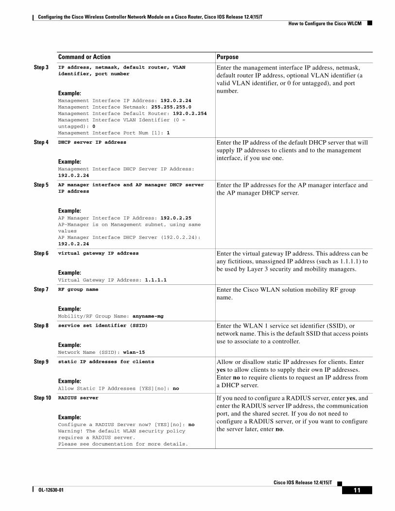
Step 3 IP address, netmask, default router, VLAN identifier, port number
Example:Management Interface IP Address: 192.0.2.24Management Interface Netmask: 255.255.255.0Management Interface Default Router: 192.0.2.254 Management Interface VLAN Identifier (0 = untagged): 0Management Interface Port Num [1]: 1
Enter the management interface IP address, netmask, default router IP address, optional VLAN identifier (a valid VLAN identifier, or 0 for untagged), and port number.
Step 4 DHCP server IP address
Example:Management Interface DHCP Server IP Address: 192.0.2.24
Enter the IP address of the default DHCP server that will supply IP addresses to clients and to the management interface, if you use one.
Step 5 AP manager interface and AP manager DHCP server IP address
Example:AP Manager Interface IP Address: 192.0.2.25AP-Manager is on Management subnet, using same valuesAP Manager Interface DHCP Server (192.0.2.24): 192.0.2.24
Enter the IP addresses for the AP manager interface and the AP manager DHCP server.
Step 6 virtual gateway IP address
Example:Virtual Gateway IP Address: 1.1.1.1
Enter the virtual gateway IP address. This address can be any fictitious, unassigned IP address (such as 1.1.1.1) to be used by Layer 3 security and mobility managers.
Step 7 RF group name
Example:Mobility/RF Group Name: anyname-mg
Enter the Cisco WLAN solution mobility RF group name.
Step 8 service set identifier (SSID)
Example:Network Name (SSID): wlan-15
Enter the WLAN 1 service set identifier (SSID), or network name. This is the default SSID that access points use to associate to a controller.
Step 9 static IP addresses for clients
Example:Allow Static IP Addresses [YES][no]: no
Allow or disallow static IP addresses for clients. Enter yes to allow clients to supply their own IP addresses. Enter no to require clients to request an IP address from a DHCP server.
Step 10 RADIUS server
Example:Configure a RADIUS Server now? [YES][no]: noWarning! The default WLAN security policy requires a RADIUS server.Please see documentation for more details.
If you need to configure a RADIUS server, enter yes, and enter the RADIUS server IP address, the communication port, and the shared secret. If you do not need to configure a RADIUS server, or if you want to configure the server later, enter no.
Command or Action Purpose
11Cisco IOS Release 12.4(15)T
OL-12630-01
Configuring the Cisco Wireless Controller Network Module on a Cisco Router, Cisco IOS Release 12.4(15)T How to Configure the Cisco WLCM
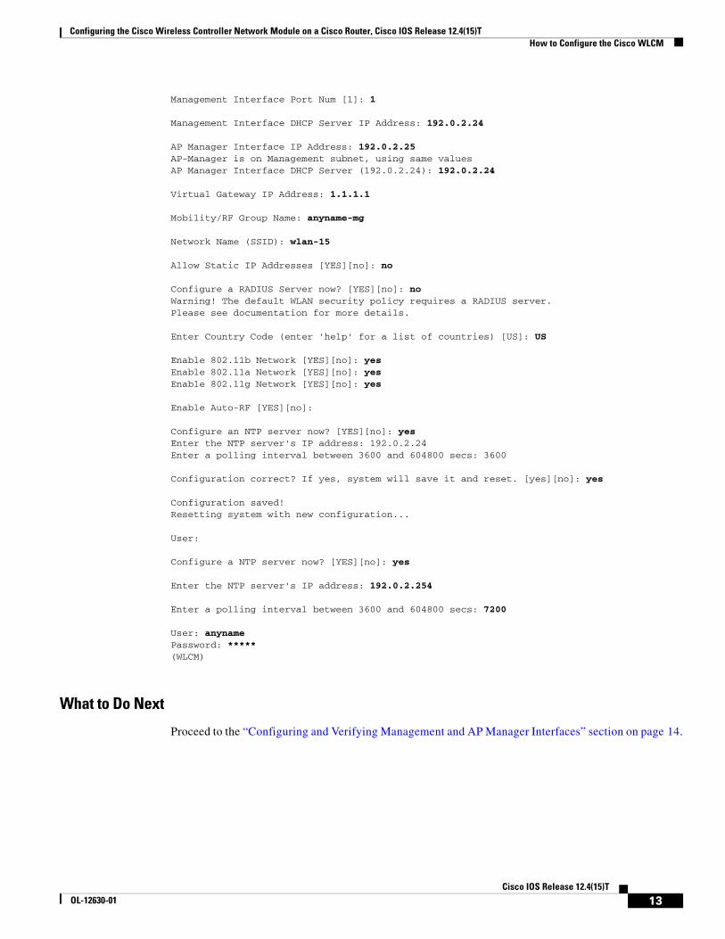
Configuration Example for Running the Configuration Wizard
The following example shows the settings by using the wizard on the CLI:
Welcome to the Cisco Wizard Configuration ToolUse the '-' character to backupWLCM:# anyname
Enter Administrative User Name (24 characters max): anynameEnter Administrative Password (24 characters max): *****
Example:Enter Country Code (enter 'help' for a list of countries) [US]: US
Enter a country code for the unit. To see a list of the supported country codes, enter help or see the Cisco Wireless LAN Solution Product Guide at the following URL:
Enable or disable support for 802.11b, 802.11a, and 802.11g.
Step 13 radio resource management (RRM) (auto RF)
Example:Enable Auto-RF [YES][no]:
Enable or disable radio resource management (RRM) (auto RF).
Note The controller saves the configuration, reboots with your changes, and prompts you to log in or to enter recover-config to reset to the factory default configuration and return to the wizard.
When the configuration wizard has completed initial configuration, the Cisco WLCM automatically reboots with the new configuration and stops at the User prompt.
Step 14 NTP server IP address and polling interval
Example:Configure a NTP server now? [YES][no]: yes Enter the NTP server's IP address: 192.0.2.254Enter a polling interval between 3600 and 604800 secs: 7200
You are prompted to configure the Network Time Protocol (NTP) server if necessary.
If you answer yes to configuring the NTP server, you are prompted to provide the NTP server IP address.
If you answer yes to configuring the NTP server, you are also prompted to provide the polling interval.
Configuring the Cisco Wireless Controller Network Module on a Cisco Router, Cisco IOS Release 12.4(15)T How to Configure the Cisco WLCM
Management Interface Port Num [1]: 1
Management Interface DHCP Server IP Address: 192.0.2.24
AP Manager Interface IP Address: 192.0.2.25AP-Manager is on Management subnet, using same valuesAP Manager Interface DHCP Server (192.0.2.24): 192.0.2.24
Virtual Gateway IP Address: 1.1.1.1
Mobility/RF Group Name: anyname-mg
Network Name (SSID): wlan-15
Allow Static IP Addresses [YES][no]: no
Configure a RADIUS Server now? [YES][no]: noWarning! The default WLAN security policy requires a RADIUS server.Please see documentation for more details.
Enter Country Code (enter 'help' for a list of countries) [US]: US
Configure an NTP server now? [YES][no]: yes Enter the NTP server's IP address: 192.0.2.24 Enter a polling interval between 3600 and 604800 secs: 3600
Configuration correct? If yes, system will save it and reset. [yes][no]: yes
Configuration saved!Resetting system with new configuration...
User:
Configure a NTP server now? [YES][no]: yes
Enter the NTP server's IP address: 192.0.2.254
Enter a polling interval between 3600 and 604800 secs: 7200
User: anynamePassword: *****(WLCM)
What to Do Next
Proceed to the “Configuring and Verifying Management and AP Manager Interfaces” section on page 14.
13Cisco IOS Release 12.4(15)T
OL-12630-01
Configuring the Cisco Wireless Controller Network Module on a Cisco Router, Cisco IOS Release 12.4(15)T How to Configure the Cisco WLCM
Configuring and Verifying Management and AP Manager InterfacesYou can create any number of static or dynamic logical interfaces on the Cisco WLCM, configured as VLAN tagged interfaces or untagged interfaces. By default, two static untagged interfaces are assigned (management interface and ap-manager interface) and used for management and communication with APs. Because these interfaces are untagged, they must be assigned to the same subnet that is used to configure the WLCM interface on the router.
Configuration Examples for Verifying Management and AP Manager Interfaces
The management interface must have an IP address that can be reached from the workstation that is managing the interface. The AP manager interface allows the WLCM to communicate with APs.
Proceed to the “Configuring Wide-Area LANs on the Cisco WLCM” section on page 15.
Configuring Wide-Area LANs on the Cisco WLCMThe Cisco WLCM can control up to 16 wireless LANs for access points. Each wireless LAN has a separate wireless LAN ID (1 through 16) and a separate wireless LAN SSID (wireless LAN name). Each wireless LAN can be assigned unique security policies.
Note The Cisco AIR-AP1000 series support 16 SSIDs; however, the Cisco AIR-AP1130 series and the Cisco AIR-AP1240 series can support only 8 SSIDs.
Note We recommend that you assign one set of VLANs for wireless LANs and a different set of VLANs for management interfaces to ensure that controllers properly route VLAN traffic. Configure VLANs on the integrated-service-engine interface using IEEE 802.1Q trunking encapsulation. The number of VLANs that are configured on the router integrated-service-engine interface should be equal to the number of VLAN tags used on the Cisco WLCM.
Native VLAN is not supported on the Cisco WLCM; therefore, the router should not have any functional native VLANs configured.
For additional information about configuring VLANs on the Cisco WLCM, see the Cisco Wireless LAN Solution Product Guide at the following URL:
Configuring the Cisco Wireless Controller Network Module on a Cisco Router, Cisco IOS Release 12.4(15)T How to Configure the Cisco WLCM
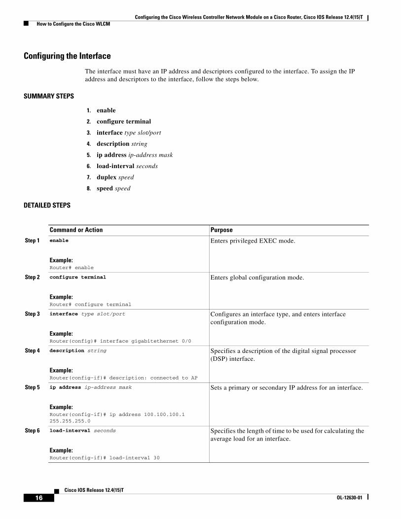
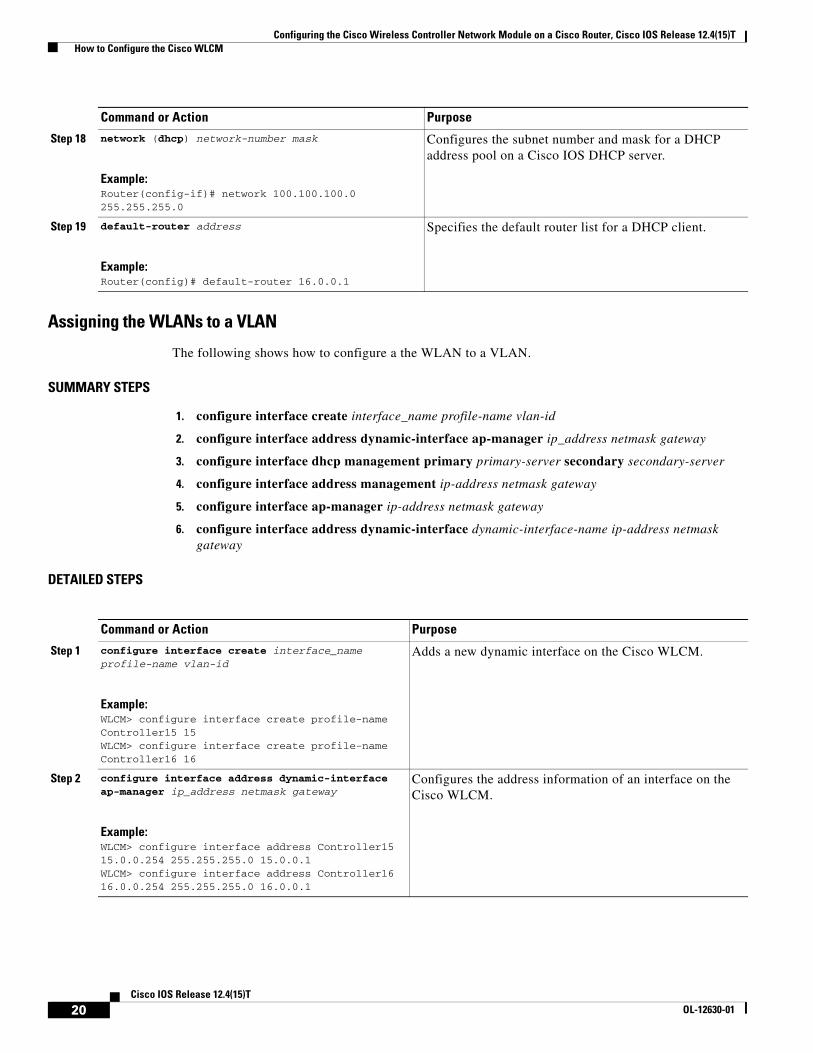
Configuring the Interface
The interface must have an IP address and descriptors configured to the interface. To assign the IP address and descriptors to the interface, follow the steps below.
Configures DHCP server options for the Cisco WLAN 1000 series AP.
Note To use the option command to configure DHCP server options on the Cisco WLAN 1100 series and Cisco 1200 series APs, use the option command and specifying the hex string. For complete information about configuring DHCP on Cisco WLCM products, see the Cisco 440X Series Wireless LAN Controllers Deployment Guide at the following URL:http://www.cisco.com/en/US/docs/wireless/technology/controller/deployment/guide/dep.html
Configures the address information of an interface on the Cisco WLCM.
20Cisco IOS Release 12.4(15)T
OL-12630-01
Configuring the Cisco Wireless Controller Network Module on a Cisco Router, Cisco IOS Release 12.4(15)T How to Configure the Cisco WLCM
Configuration Examples for Creating VLANs
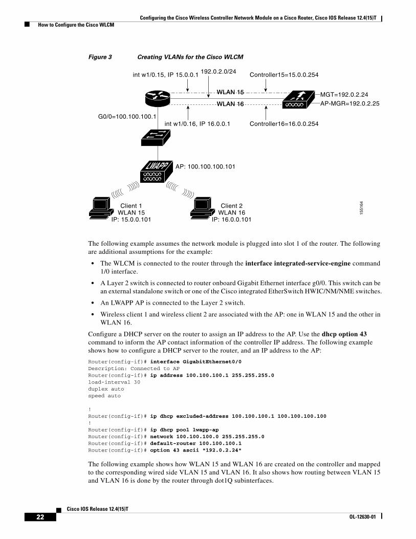
The Cisco WLCM that is installed in the router can be logically considered to be equivalent to an external wireless LAN controller that is connected to the router through an Ethernet interface, as shown in Figure 3.
Configures the dynamic interface address on the Cisco WLCM.
Command or Action Purpose
21Cisco IOS Release 12.4(15)T
OL-12630-01
Configuring the Cisco Wireless Controller Network Module on a Cisco Router, Cisco IOS Release 12.4(15)T How to Configure the Cisco WLCM
Figure 3 Creating VLANs for the Cisco WLCM
The following example assumes the network module is plugged into slot 1 of the router. The following are additional assumptions for the example:
• The WLCM is connected to the router through the interface integrated-service-engine command 1/0 interface.
• A Layer 2 switch is connected to router onboard Gigabit Ethernet interface g0/0. This switch can be an external standalone switch or one of the Cisco integrated EtherSwitch HWIC/NM/NME switches.
• An LWAPP AP is connected to the Layer 2 switch.
• Wireless client 1 and wireless client 2 are associated with the AP: one in WLAN 15 and the other in WLAN 16.
Configure a DHCP server on the router to assign an IP address to the AP. Use the dhcp option 43 command to inform the AP contact information of the controller IP address. The following example shows how to configure a DHCP server to the router, and an IP address to the AP:
Router(config-if)# interface GigabitEthernet0/0Description: Connected to APRouter(config-if)# ip address 100.100.100.1 255.255.255.0load-interval 30duplex autospeed auto
!Router(config-if)# ip dhcp excluded-address 100.100.100.1 100.100.100.100!Router(config-if)# ip dhcp pool lwapp-apRouter(config-if)# network 100.100.100.0 255.255.255.0Router(config-if)# default-router 100.100.100.1 Router(config-if)# option 43 ascii "192.0.2.24"
The following example shows how WLAN 15 and WLAN 16 are created on the controller and mapped to the corresponding wired side VLAN 15 and VLAN 16. It also shows how routing between VLAN 15 and VLAN 16 is done by the router through dot1Q subinterfaces.
WLAN 15
WLAN 16
WLAN 15
int w1/0.15, IP 15.0.0.1 Controller15=15.0.0.254
Controller16=16.0.0.254
MGT=192.0.2.24
AP-MGR=192.0.2.25WLAN 16
G0/0=100.100.100.1int w1/0.16, IP 16.0.0.1
AP: 100.100.100.101
192.0.2.0/24
Client 1WLAN 15
IP: 15.0.0.101
Client 2WLAN 16
IP: 16.0.0.101
1551
64
22Cisco IOS Release 12.4(15)T
OL-12630-01
Configuring the Cisco Wireless Controller Network Module on a Cisco Router, Cisco IOS Release 12.4(15)T How to Configure the Cisco WLCM
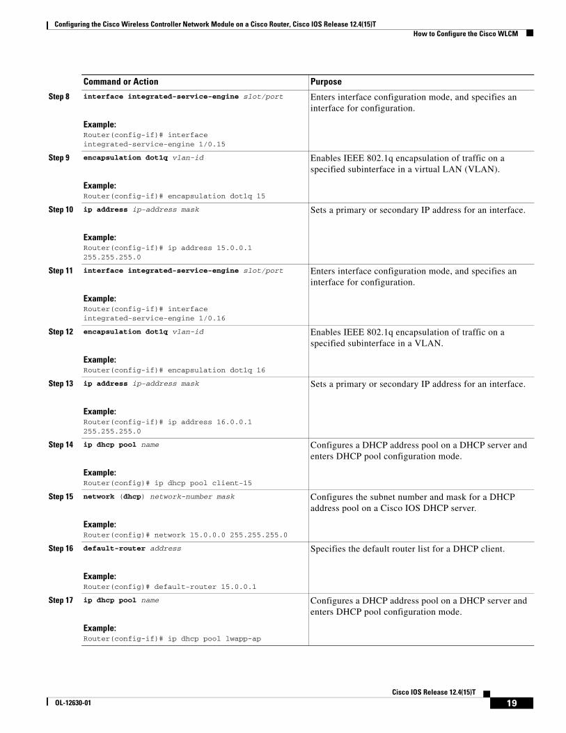
On the router, create one subinterface under integrated-service-engine interface (in interface configuration mode) for every VLAN, assign it to the corresponding VLAN, and configure an IP address from the respective subnets.
Router(config-if)# interface integrated-service-engine 1/0Router(config-if)# ip address 192.0.2.254 255.255.255.0!Router(config-if)# interface integrated-service-engine 1/0.15Router(config-if)# encapsulation Dot1q 15Router(config-if)# ip address 15.0.0.1 255.255.255.0!Router(config-if)# interface integrated-service-engine 1/0.16Router(config-if)# encapsulation Dot1q 16Router(config-if)# ip address 16.0.0.1 255.255.255.0
On the router, create two DHCP pools from subnet 15.0.0.0/24 and 16.0.0.0/24, and assign IP address information to the wireless clients in WLAN 15 and WLAN 16.
Note DHCP services for clients can also run on the controller, but we recommend running DHCP services on the router because the controller is not a full-fledged DHCP server and will not pass on such options as TFTP server required for applications such as Cisco Call Manager Express.
Router(config)# ip dhcp pool client-15Router(config)# network 15.0.0.0 255.255.255.0Router(config)# default-router 15.0.0.1
Router(config)# ip dhcp pool client-16Router(config)# network 16.0.0.0 255.255.255.0Router(config)# default-router 16.0.0.1
For every VLAN on the controller, create one dynamic interface to the corresponding VLAN and assign an IP address, a subnet mask, and default gateways from the subnets.
The traffic from WLAN 15 client that is destined to the WLAN 16 client will be routed between the subinterfaces that have been created in the preceding steps.
23Cisco IOS Release 12.4(15)T
OL-12630-01
Configuring the Cisco Wireless Controller Network Module on a Cisco Router, Cisco IOS Release 12.4(15)T How to Configure the Cisco WLCM
Note The controller supports a maximum number of 16 VLANs.
What to Do Next
Proceed to the “Configuring VLANs with APs Connected to an External Switch” section on page 24.
Configuring VLANs with APs Connected to an External SwitchThe WLCM in the router is considered equivalent to an external wireless LAN controller connected to the router through an Ethernet interface.
Restrictions
• The WLCM is installed in slot 1 of the router.
• A Layer 2 switch is connected to the router onboard Fast Ethernet interface f0/0.
• An LWAPP AP is connected to the switch.
• Wireless clients C1 and C2 are associated with the AP. Either wireless client can be associated with either WLAN 15 or WLAN 16.
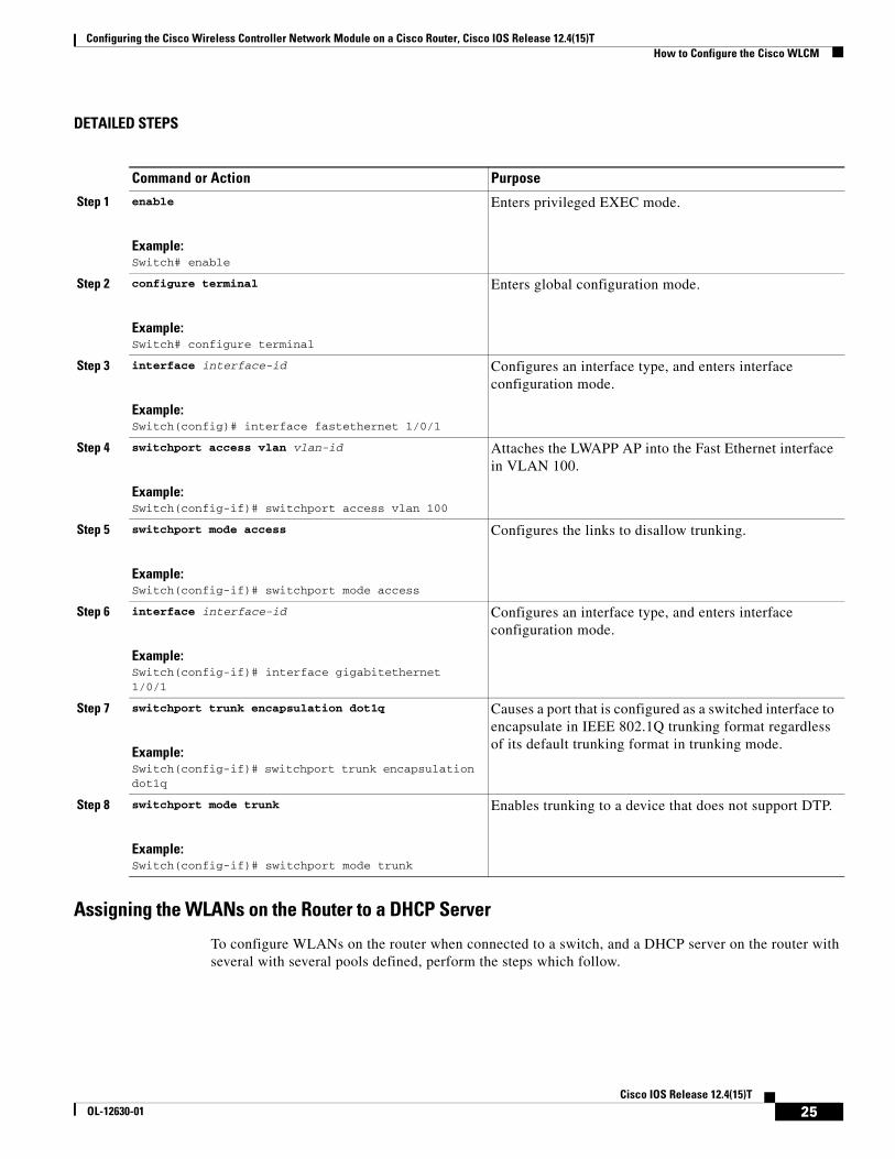
Configuring the Switch Port
Configure a Fast Ethernet interface from the Catalyst 3750 switch to the LWAPP AP and configure a Gigabit Ethernet trunking interface from the Catalyst 3750 switch to the router. To assign these interfaces on the Catalyst 3750 switch, follow the steps below.
SUMMARY STEPS
1. enable
2. configure terminal
3. interface interface-id
4. switchport access vlan vlan-id
5. switchport mode access
6. interface interface-id
7. switchport trunk encapsulation dot1q
8. switchport mode trunk
24Cisco IOS Release 12.4(15)T
OL-12630-01
Configuring the Cisco Wireless Controller Network Module on a Cisco Router, Cisco IOS Release 12.4(15)T How to Configure the Cisco WLCM
DETAILED STEPS
Assigning the WLANs on the Router to a DHCP Server
To configure WLANs on the router when connected to a switch, and a DHCP server on the router with several with several pools defined, perform the steps which follow.
Causes a port that is configured as a switched interface to encapsulate in IEEE 802.1Q trunking format regardless of its default trunking format in trunking mode.
Step 8 switchport mode trunk
Example:Switch(config-if)# switchport mode trunk
Enables trunking to a device that does not support DTP.
25Cisco IOS Release 12.4(15)T
OL-12630-01
Configuring the Cisco Wireless Controller Network Module on a Cisco Router, Cisco IOS Release 12.4(15)T How to Configure the Cisco WLCM
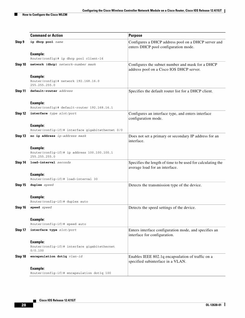
Note DHCP services for the clients can also be run on the WLCM, however, we recommend running DHCP services on the router because the WLCM is not a full-fledged DHCP server and can not pass on TFTP server options required for applications like Cisco Call Manager Express.
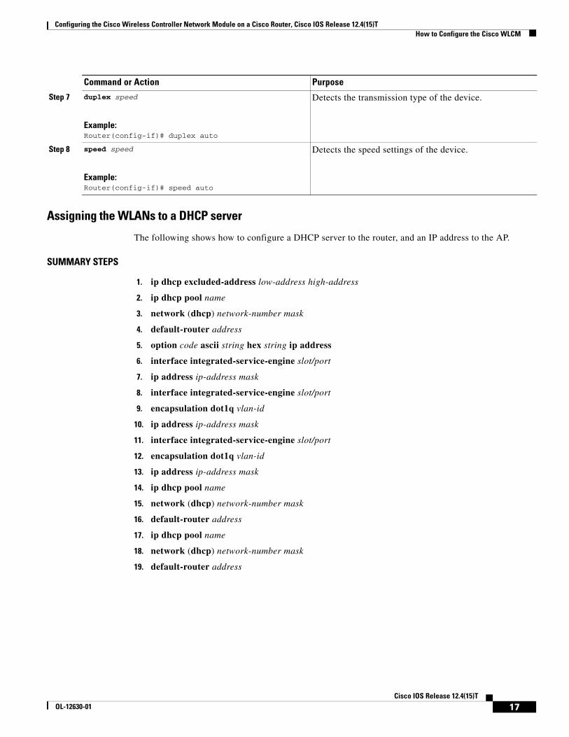
SUMMARY STEPS
1. ip dhcp excluded-address low-address high-address
2. ip dhcp pool name
3. network (dhcp) network-number mask
4. default-router address
5. option code ascii string hex string ip address
6. ip dhcp pool name
7. network (dhcp) network-number mask
8. default-router address
9. ip dhcp pool name
10. network (dhcp) network-number mask
11. default-router address
12. interface type slot/port
13. no ip address ip-address mask
14. load-interval seconds
15. duplex speed
16. speed speed
17. interface type slot/port
18. encapsulation dot1q vlan-id
19. ip address ip-address mask
20. interface integrated-service-engine slot/port
21. ip address ip-address mask
22. interface integrated-service-engine slot/port
23. encapsulation dot1q vlan-id
24. ip address ip-address mask
25. interface integrated-service-engine slot/port
26. encapsulation dot1q vlan-id
27. ip address ip-address mask
26Cisco IOS Release 12.4(15)T
OL-12630-01
Configuring the Cisco Wireless Controller Network Module on a Cisco Router, Cisco IOS Release 12.4(15)T How to Configure the Cisco WLCM
DETAILED STEPS
Command or Action Purpose
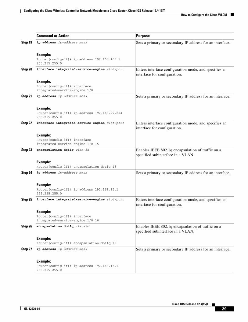
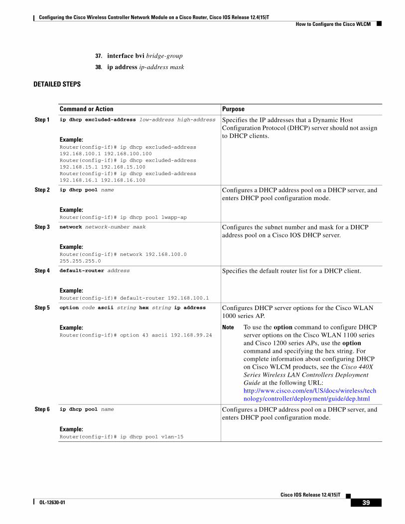
Step 1 ip dhcp excluded-address low-address high-address
Example:Router(config-if)# ip dhcp excluded-address 192.168.100.1 192.168.100.100
Specifies the IP addresses that a Dynamic Host Configuration Protocol (DHCP) server should not assign to DHCP clients.
Step 2 ip dhcp pool name
Example:Router(config-if)# ip dhcp pool lwapp-ap
Configures a DHCP address pool on a DHCP server, and enters DHCP pool configuration mode.
Configures DHCP server options for the Cisco WLAN 1000 series AP.
Note To use the option command to configure DHCP server options on the Cisco WLAN 1100 series and Cisco 1200 series APs, use the option command and specify the hex string. For complete information about configuring DHCP on Cisco WLCM products, see the Cisco 440X Series Wireless LAN Controllers Deployment Guide at the following URL: http://www.cisco.com/en/US/docs/wireless/technology/controller/deployment/guide/dep.html
Step 6 ip dhcp pool name
Example:Router(config)# ip dhcp pool client-15
Configures a DHCP address pool on a DHCP server, and enters DHCP pool configuration mode.
Configures the DHCP options on the WLCM interface.
30Cisco IOS Release 12.4(15)T
OL-12630-01
Configuring the Cisco Wireless Controller Network Module on a Cisco Router, Cisco IOS Release 12.4(15)T How to Configure the Cisco WLCM
What to Do Next
Proceed to the “Configuring APs Connected to an EtherSwitch Module on the Router” section on page 31.
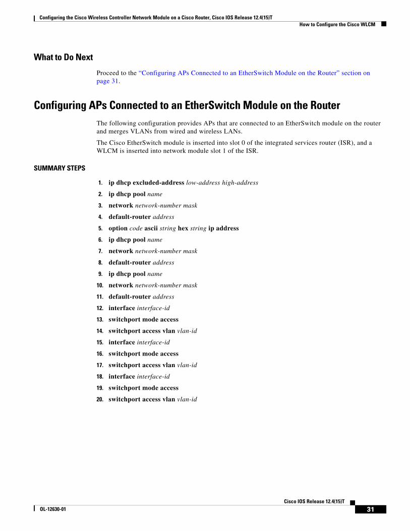
Configuring APs Connected to an EtherSwitch Module on the RouterThe following configuration provides APs that are connected to an EtherSwitch module on the router and merges VLANs from wired and wireless LANs.
The Cisco EtherSwitch module is inserted into slot 0 of the integrated services router (ISR), and a WLCM is inserted into network module slot 1 of the ISR.
SUMMARY STEPS
1. ip dhcp excluded-address low-address high-address
2. ip dhcp pool name
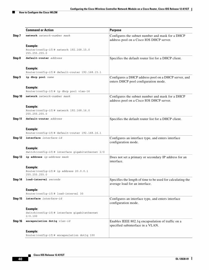
3. network network-number mask
4. default-router address
5. option code ascii string hex string ip address
6. ip dhcp pool name
7. network network-number mask
8. default-router address
9. ip dhcp pool name
10. network network-number mask
11. default-router address
12. interface interface-id
13. switchport mode access
14. switchport access vlan vlan-id
15. interface interface-id
16. switchport mode access
17. switchport access vlan vlan-id
18. interface interface-id
19. switchport mode access
20. switchport access vlan vlan-id
31Cisco IOS Release 12.4(15)T
OL-12630-01
Configuring the Cisco Wireless Controller Network Module on a Cisco Router, Cisco IOS Release 12.4(15)T How to Configure the Cisco WLCM
DETAILED STEPS
Command or Action Purpose
Step 1 ip dhcp excluded-address low-address high-address
Example:Router(config-if)# ip dhcp excluded-address 192.168.100.1 192.168.100.100Router(config-if)# ip dhcp excluded-address 192.168.15.1 192.168.15.100Router(config-if)# ip dhcp excluded-address 192.168.16.1 192.168.16.100
Specifies the IP addresses that a Dynamic Host Configuration Protocol (DHCP) server should not assign to DHCP clients.
Step 2 ip dhcp pool name
Example:Router(config-if)# ip dhcp pool lwapp-ap
Configures a DHCP address pool on a DHCP server, and enters DHCP pool configuration mode.
Configures DHCP server options for the Cisco WLAN 1000 series AP.
Note To use the option command to configure DHCP server options on the Cisco WLAN 1100 series and Cisco 1200 series APs, use the option command and specify the hex string. For complete information about configuring DHCP on Cisco WLCM products, see the Cisco 440X Series Wireless LAN Controllers Deployment Guide at the following URL: http://www.cisco.com/en/US/docs/wireless/technology/controller/deployment/guide/dep.html
Step 6 ip dhcp pool name
Example:Router(config)# ip dhcp pool vlan-15
Configures a DHCP address pool on a DHCP server, and enters DHCP pool configuration mode.
Attaches the LWAPP AP to the Fast Ethernet interface in VLAN 15.
Command or Action Purpose
33Cisco IOS Release 12.4(15)T
OL-12630-01
Configuring the Cisco Wireless Controller Network Module on a Cisco Router, Cisco IOS Release 12.4(15)T How to Configure the Cisco WLCM
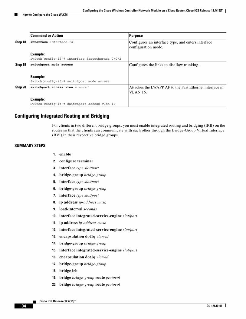
Configuring Integrated Routing and Bridging
For clients in two different bridge groups, you must enable integrated routing and bridging (IRB) on the router so that the clients can communicate with each other through the Bridge-Group Virtual Interface (BVI) in their respective bridge groups.
Enters interface configuration mode, and specifies an interface for configuration.
Step 16 encapsulation dot1q vlan-id
Example:Router(config-if)# encapsulation dot1q 16
Enables IEEE 802.1q encapsulation of traffic on a specified subinterface in a VLAN.
Step 17 bridge-group bridge-group
Example:Router(config-if)# bridge-group 16
Assigns an interface to a bridge group. The bridge group must be an integer between 1 and 63.
Step 18 bridge irb
Example:Router(config-if)# bridge irb
Enables Cisco IOS software to route a given protocol between routed interfaces and bridge groups or to route a given protocol between bridge groups.
Command or Action Purpose
36Cisco IOS Release 12.4(15)T
OL-12630-01
Configuring the Cisco Wireless Controller Network Module on a Cisco Router, Cisco IOS Release 12.4(15)T How to Configure the Cisco WLCM
What to Do Next
Proceed to the “Configuring Wired VLANs on the EtherSwitch Module with Wireless VLANs on the WLCM” section on page 37.
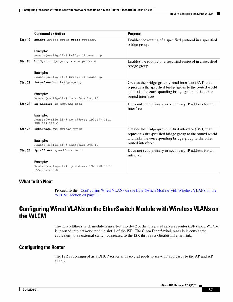
Configuring Wired VLANs on the EtherSwitch Module with Wireless VLANs on the WLCM
The Cisco EtherSwitch module is inserted into slot 2 of the integrated services router (ISR) and a WLCM is inserted into network module slot 1 of the ISR. The Cisco EtherSwitch module is considered equivalent to an external switch connected to the ISR through a Gigabit Ethernet link.
Configuring the Router
The ISR is configured as a DHCP server with several pools to serve IP addresses to the AP and AP clients.
Step 19 bridge bridge-group route protocol
Example:Router(config-if)# bridge 15 route ip
Enables the routing of a specified protocol in a specified bridge group.
Step 20 bridge bridge-group route protocol
Example:Router(config-if)# bridge 16 route ip
Enables the routing of a specified protocol in a specified bridge group.
Step 21 interface bvi bridge-group
Example:Router(config-if)# interface bvi 15
Creates the bridge-group virtual interface (BVI) that represents the specified bridge group to the routed world and links the corresponding bridge group to the other routed interfaces.
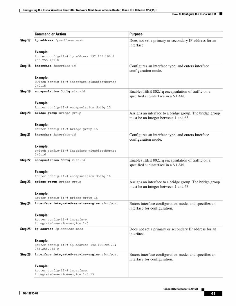
Step 22 ip address ip-address mask
Example:Router(config-if)# ip address 192.168.15.1 255.255.255.0
Does not set a primary or secondary IP address for an interface.
Step 23 interface bvi bridge-group
Example:Router(config-if)# interface bvi 16
Creates the bridge-group virtual interface (BVI) that represents the specified bridge group to the routed world and links the corresponding bridge group to the other routed interfaces.
Step 24 ip address ip-address mask
Example:Router(config-if)# ip address 192.168.16.1 255.255.255.0
Does not set a primary or secondary IP address for an interface.
Command or Action Purpose
37Cisco IOS Release 12.4(15)T
OL-12630-01
Configuring the Cisco Wireless Controller Network Module on a Cisco Router, Cisco IOS Release 12.4(15)T How to Configure the Cisco WLCM
SUMMARY STEPS
1. ip dhcp excluded-address low-address high-address
2. ip dhcp pool name
3. network network-number mask
4. default-router address
5. option code ascii string hex string ip address
6. ip dhcp pool name
7. network network-number mask
8. default-router address
9. ip dhcp pool name
10. network network-number mask
11. default-router address
12. interface interface-id
13. ip address ip-address mask
14. load-interval seconds
15. interface type slot/port
16. encapsulation dot1q vlan-id
17. ip address ip-address mask
18. interface type slot/port
19. encapsulation dot1q vlan-id
20. bridge-group bridge-group
21. interface type slot/port
22. encapsulation dot1q vlan-id
23. bridge-group bridge-group
24. interface integrated-service-engine slot/port
25. ip address ip-address mask
26. interface integrated-service-engine slot/port
27. encapsulation dot1q vlan-id
28. bridge-group bridge-group
29. interface integrated-service-engine slot/port
30. encapsulation dot1q vlan-id
31. bridge-group bridge-group
32. bridge irb
33. bridge bridge-group route protocol
34. bridge bridge-group route protocol
35. interface bvi bridge-group
36. ip address ip-address mask
38Cisco IOS Release 12.4(15)T
OL-12630-01
Configuring the Cisco Wireless Controller Network Module on a Cisco Router, Cisco IOS Release 12.4(15)T How to Configure the Cisco WLCM
37. interface bvi bridge-group
38. ip address ip-address mask
DETAILED STEPS
Command or Action Purpose
Step 1 ip dhcp excluded-address low-address high-address
Example:Router(config-if)# ip dhcp excluded-address 192.168.100.1 192.168.100.100Router(config-if)# ip dhcp excluded-address 192.168.15.1 192.168.15.100Router(config-if)# ip dhcp excluded-address 192.168.16.1 192.168.16.100
Specifies the IP addresses that a Dynamic Host Configuration Protocol (DHCP) server should not assign to DHCP clients.
Step 2 ip dhcp pool name
Example:Router(config-if)# ip dhcp pool lwapp-ap
Configures a DHCP address pool on a DHCP server, and enters DHCP pool configuration mode.
Configures DHCP server options for the Cisco WLAN 1000 series AP.
Note To use the option command to configure DHCP server options on the Cisco WLAN 1100 series and Cisco 1200 series APs, use the option command and specifying the hex string. For complete information about configuring DHCP on Cisco WLCM products, see the Cisco 440X Series Wireless LAN Controllers Deployment Guide at the following URL: http://www.cisco.com/en/US/docs/wireless/technology/controller/deployment/guide/dep.html
Step 6 ip dhcp pool name
Example:Router(config-if)# ip dhcp pool vlan-15
Configures a DHCP address pool on a DHCP server, and enters DHCP pool configuration mode.
Enters interface configuration mode, and specifies an interface for configuration.
Step 30 encapsulation dot1q vlan-id
Example:Router(config-if)# encapsulation dot1q 16
Enables IEEE 802.1q encapsulation of traffic on a specified subinterface in a VLAN.
Step 31 bridge-group bridge-group
Example:Router(config-if)# bridge-group 16
Assigns an interface to a bridge group. The bridge group must be an integer between 1 and 63.
Step 32 bridge irb
Example:Router(config-if)# bridge irb
Enables Cisco IOS software to route a given protocol between routed interfaces and bridge groups or to route a given protocol between bridge groups.
Step 33 bridge bridge-group route protocol
Example:Router(config-if)# bridge 15 route ip
Enables the routing of a specified protocol in a specified bridge group.
Step 34 bridge bridge-group route protocol
Example:Router(config-if)# bridge 16 route ip
Enables the routing of a specified protocol in a specified bridge group.
Step 35 interface bvi bridge-group
Example:Router(config-if)# interface bvi 15
Creates the bridge-group virtual interface (BVI) that represents the specified bridge group to the routed world and links the corresponding bridge group to the other routed interfaces.
Step 36 ip address ip-address mask
Example:Router(config-if)# ip address 192.168.15.1 255.255.255.0
Does not set a primary or secondary IP address for an interface.
Command or Action Purpose
42Cisco IOS Release 12.4(15)T
OL-12630-01
Configuring the Cisco Wireless Controller Network Module on a Cisco Router, Cisco IOS Release 12.4(15)T How to Configure the Cisco WLCM
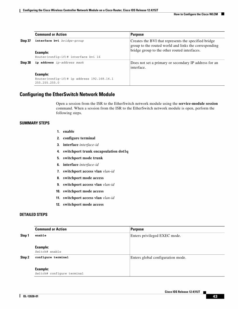
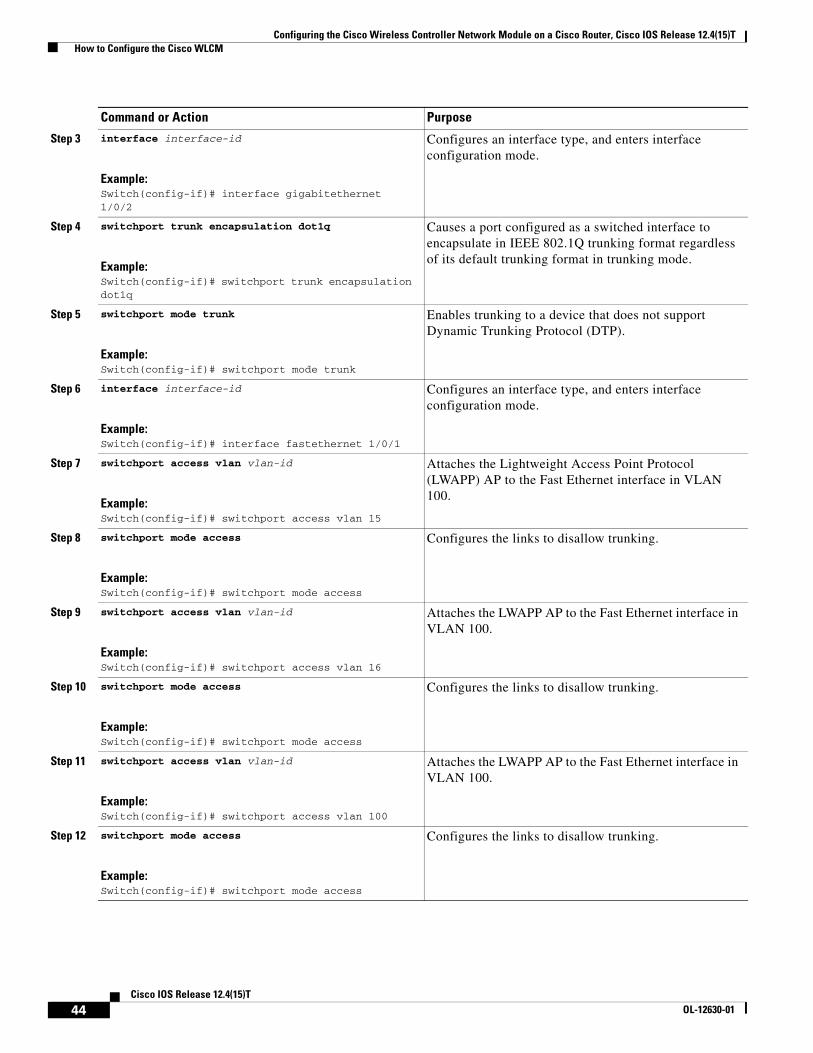
Configuring the EtherSwitch Network Module
Open a session from the ISR to the EtherSwitch network module using the service-module session command. When a session from the ISR to the EtherSwitch network module is open, perform the following steps.
SUMMARY STEPS
1. enable
2. configure terminal
3. interface interface-id
4. switchport trunk encapsulation dot1q
5. switchport mode trunk
6. interface interface-id
7. switchport access vlan vlan-id
8. switchport mode access
9. switchport access vlan vlan-id
10. switchport mode access
11. switchport access vlan vlan-id
12. switchport mode access
DETAILED STEPS
Step 37 interface bvi bridge-group
Example:Router(config-if)# interface bvi 16
Creates the BVI that represents the specified bridge group to the routed world and links the corresponding bridge group to the other routed interfaces.
Step 38 ip address ip-address mask
Example:Router(config-if)# ip address 192.168.16.1 255.255.255.0
Does not set a primary or secondary IP address for an interface.
Command or Action Purpose
Command or Action Purpose
Step 1 enable
Example:Switch# enable
Enters privileged EXEC mode.
Step 2 configure terminal
Example:Switch# configure terminal
Enters global configuration mode.
43Cisco IOS Release 12.4(15)T
OL-12630-01
Configuring the Cisco Wireless Controller Network Module on a Cisco Router, Cisco IOS Release 12.4(15)T How to Configure the Cisco WLCM
Causes a port configured as a switched interface to encapsulate in IEEE 802.1Q trunking format regardless of its default trunking format in trunking mode.
Step 5 switchport mode trunk
Example:Switch(config-if)# switchport mode trunk
Enables trunking to a device that does not support Dynamic Trunking Protocol (DTP).
Attaches the LWAPP AP to the Fast Ethernet interface in VLAN 100.
Step 12 switchport mode access
Example:Switch(config-if)# switchport mode access
Configures the links to disallow trunking.
Command or Action Purpose
44Cisco IOS Release 12.4(15)T
OL-12630-01
Configuring the Cisco Wireless Controller Network Module on a Cisco Router, Cisco IOS Release 12.4(15)T How to Configure the Cisco WLCM
What to Do Next
Proceed to the “Upgrading the Cisco WLCM Software” section on page 45.
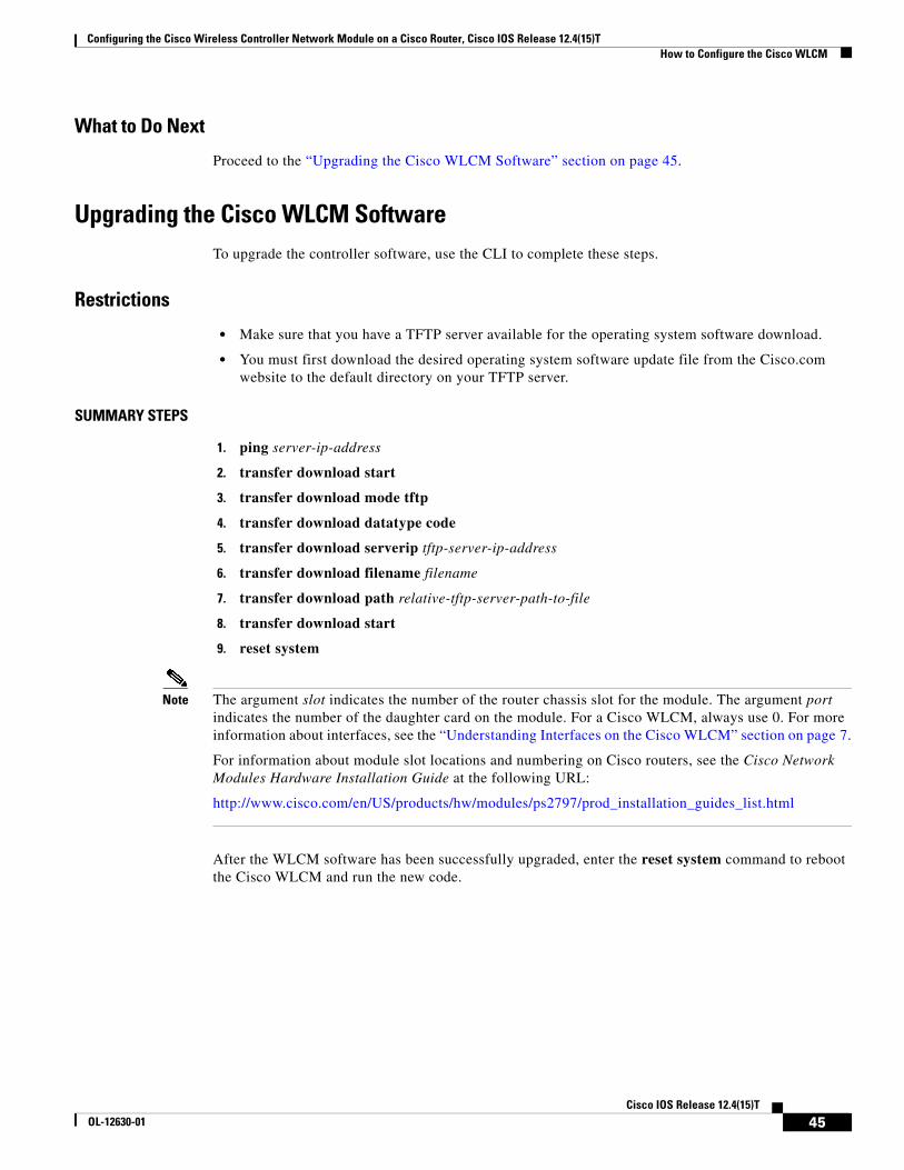
Upgrading the Cisco WLCM SoftwareTo upgrade the controller software, use the CLI to complete these steps.
Restrictions
• Make sure that you have a TFTP server available for the operating system software download.
• You must first download the desired operating system software update file from the Cisco.com website to the default directory on your TFTP server.
SUMMARY STEPS
1. ping server-ip-address
2. transfer download start
3. transfer download mode tftp
4. transfer download datatype code
5. transfer download serverip tftp-server-ip-address
6. transfer download filename filename
7. transfer download path relative-tftp-server-path-to-file
8. transfer download start
9. reset system
Note The argument slot indicates the number of the router chassis slot for the module. The argument port indicates the number of the daughter card on the module. For a Cisco WLCM, always use 0. For more information about interfaces, see the “Understanding Interfaces on the Cisco WLCM” section on page 7.
For information about module slot locations and numbering on Cisco routers, see the Cisco Network Modules Hardware Installation Guide at the following URL:
Configuring the Cisco Wireless Controller Network Module on a Cisco Router, Cisco IOS Release 12.4(15)T How to Configure the Cisco WLCM
DETAILED STEPS
Command or Action Purpose
Step 1 ping server-ip-address
Example:WLCM> ping 192.0.2.24
Verifies that the controller can contact the TFTP server.
Step 2 transfer download start
Example:WLCM> transfer download start
Begins the file transfer process.
Note Answer n to the prompt to view the current download settings.
Step 3 transfer download mode tftp
Example:WLCM> transfer download mode tftp
Sets the mode to TFTP.
Step 4 transfer download datatype code
Example:WLCM> transfer download datatype code
Sets the data type code.
Step 5 transfer download serverip tftp-server-ip-address
Example:WLCM> transfer download serverip 192.168.88.5
Sets the IP address of the TFTP server.
Step 6 transfer download filename filename
Example:WLCM> transfer download filename anyname
Sets the filename to download.
Step 7 transfer download path relative-tftp-server-path-to-file
Example:WLCM> transfer download path C:/
Sets the relative TFTP path.
Note All TFTP servers require the full pathname. For example, in Windows, the path is C:\TFTP-Root. (In UNIX, forward slashes (/) are required.)
Step 8 transfer download start
Example:WLCM> transfer download start
Allows you to view the updated settings.
Note Answer y to the prompt to confirm the current download settings and to start the operating system code download.
Step 9 reset system
Example:WLCM> reset system
Saves the code update to NVRAM and reboots the Cisco WLCM.
46Cisco IOS Release 12.4(15)T
OL-12630-01
Configuring the Cisco Wireless Controller Network Module on a Cisco Router, Cisco IOS Release 12.4(15)T How to Configure the Cisco WLCM
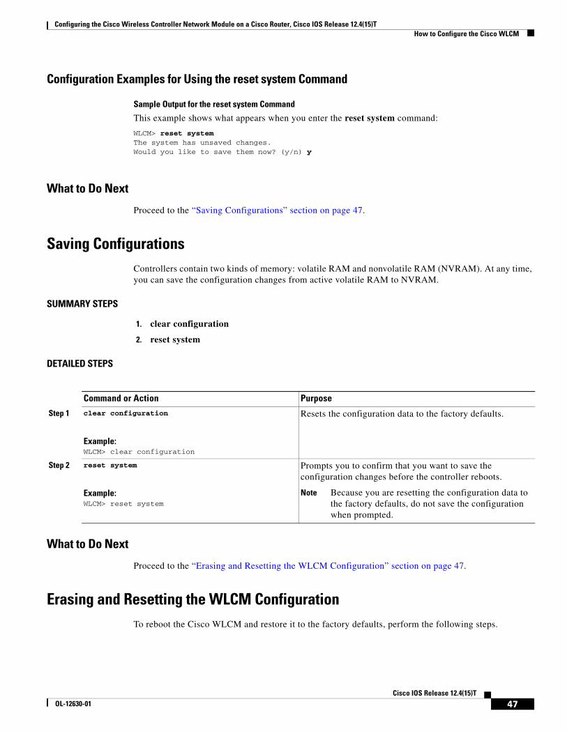
Configuration Examples for Using the reset system Command
Sample Output for the reset system Command
This example shows what appears when you enter the reset system command:
WLCM> reset systemThe system has unsaved changes.Would you like to save them now? (y/n) y
What to Do Next
Proceed to the “Saving Configurations” section on page 47.
Saving ConfigurationsControllers contain two kinds of memory: volatile RAM and nonvolatile RAM (NVRAM). At any time, you can save the configuration changes from active volatile RAM to NVRAM.
SUMMARY STEPS
1. clear configuration
2. reset system
DETAILED STEPS
What to Do Next
Proceed to the “Erasing and Resetting the WLCM Configuration” section on page 47.
Erasing and Resetting the WLCM ConfigurationTo reboot the Cisco WLCM and restore it to the factory defaults, perform the following steps.
Command or Action Purpose
Step 1 clear configuration
Example:WLCM> clear configuration
Resets the configuration data to the factory defaults.
Step 2 reset system
Example:WLCM> reset system
Prompts you to confirm that you want to save the configuration changes before the controller reboots.
Note Because you are resetting the configuration data to the factory defaults, do not save the configuration when prompted.
47Cisco IOS Release 12.4(15)T
OL-12630-01
Configuring the Cisco Wireless Controller Network Module on a Cisco Router, Cisco IOS Release 12.4(15)T Additional References
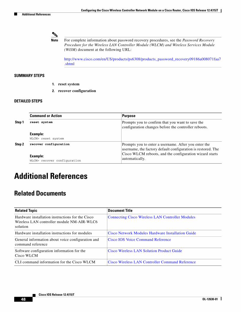
Note For complete information about password recovery procedures, see the Password Recovery Procedure for the Wireless LAN Controller Module (WLCM) and Wireless Services Module (WiSM) document at the following URL:
Prompts you to confirm that you want to save the configuration changes before the controller reboots.
Step 2 recover configuration
Example:WLCM> recover configuration
Prompts you to enter a username. After you enter the username, the factory default configuration is restored. The Cisco WLCM reboots, and the configuration wizard starts automatically.
Related Topic Document Title
Hardware installation instructions for the Cisco Wireless LAN controller module NM-AIR-WLC6 solution
Configuring the Cisco Wireless Controller Network Module on a Cisco Router, Cisco IOS Release 12.4(15)T Additional References
Technical Assistance
Description Link
Technical Assistance Center (TAC) home page, containing 30,000 pages of searchable technical content, including links to products, technologies, solutions, technical tips, and tools. Registered Cisco.com users can log in from this page to access even more content.
• show controllers integrated-service-engine, page 53
• show interfaces integrated-service-engine, page 54
50Cisco IOS Release 12.4(15)T
OL-12630-01
Configuring the Cisco Wireless Controller Network Module on a Cisco Router, Cisco IOS Release 12.4(15)T interface integrated-service-engine
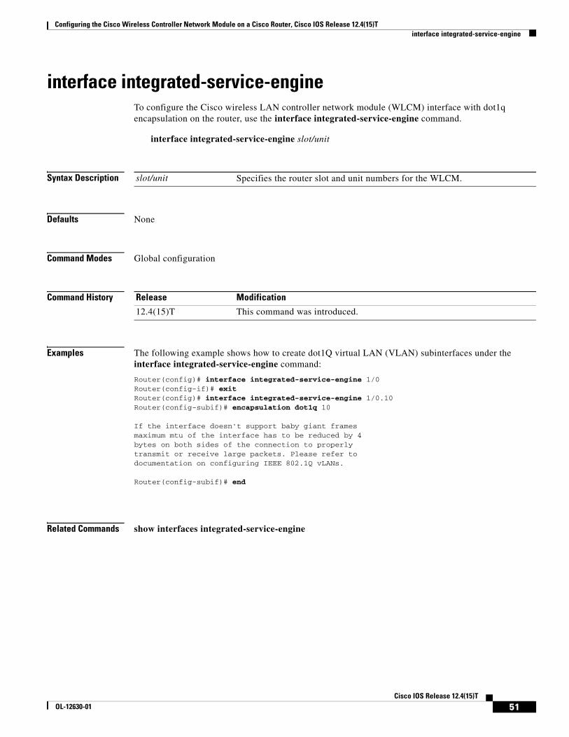
interface integrated-service-engineTo configure the Cisco wireless LAN controller network module (WLCM) interface with dot1q encapsulation on the router, use the interface integrated-service-engine command.
interface integrated-service-engine slot/unit
Syntax Description
Defaults None
Command Modes Global configuration
Command History
Examples The following example shows how to create dot1Q virtual LAN (VLAN) subinterfaces under the interface integrated-service-engine command:
Router(config)# interface integrated-service-engine 1/0Router(config-if)# exitRouter(config)# interface integrated-service-engine 1/0.10Router(config-subif)# encapsulation dot1q 10 If the interface doesn't support baby giant framesmaximum mtu of the interface has to be reduced by 4bytes on both sides of the connection to properlytransmit or receive large packets. Please refer todocumentation on configuring IEEE 802.1Q vLANs. Router(config-subif)# end
Related Commands show interfaces integrated-service-engine
slot/unit Specifies the router slot and unit numbers for the WLCM.
Release Modification
12.4(15)T This command was introduced.
51Cisco IOS Release 12.4(15)T
OL-12630-01
Configuring the Cisco Wireless Controller Network Module on a Cisco Router, Cisco IOS Release 12.4(15)T service-module integrated-service-engine
service-module integrated-service-engineTo configure the Cisco wireless LAN controller network module (WLCM) network module from the router, use the service-module integrated-service-engine command in global configuration mode.
Usage Guidelines If the Cisco WLCM has no prior configuration, the configuration wizard is automatically invoked. You cannot bypass the configuration wizard. Through the CLI, you must provide the information at the prompts provided.
Examples The following example shows how to clear the existing session on the WLCM:
Router# service-module integrated-service-engine 1/0 Router# Trying 192.0.2.254, 2066 ... Open
User:
slot/port Specifies the router slot and port numbers.
default-boot Sets or clears the default boot loader image for the next reboot.
reload Reloads the WLCM.
reset Resets the WLCM.
session Opens a session to the WLCM.
shutdown Shuts down the WLCM.
statistics Shows statistics.
status Displays information about the WLCM.
Release Modification
12.4(15)T This command was introduced.
52Cisco IOS Release 12.4(15)T
OL-12630-01
Configuring the Cisco Wireless Controller Network Module on a Cisco Router, Cisco IOS Release 12.4(15)T show controllers integrated-service-engine
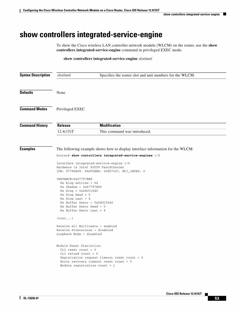
show controllers integrated-service-engineTo show the Cisco wireless LAN controller network module (WLCM) on the router, use the show controllers integrated-service-engine command in privileged EXEC mode.
show controllers integrated-service-engine slot/unit
Syntax Description
Defaults None
Command Modes Privileged EXEC
Command History
Examples The following example shows how to display interface information for the WLCM:
Router# show controllers integrated-service-engines 1/0
Interface integrated-service-engine 1/0Hardware is Intel 82559 FastEthernetIDB: 67796B08, FASTSEND: 60E073CC, MCI_INDEX: 0 INSTANCE=0x67797BE8 Rx Ring entries = 64 Rx Shadow = 0x67797ED0 Rx Ring = 0x2DCC1840 Rx Ring Head = 5 Rx Ring Last = 4 Rx Buffer Descr = 0x2DCC3040 Rx Buffer Descr Head = 5 Rx Buffer Descr Last = 4 (cont...)
slot/unit Specifies the router slot and unit numbers for the WLCM.
Release Modification
12.4(15)T This command was introduced.
53Cisco IOS Release 12.4(15)T
OL-12630-01
Configuring the Cisco Wireless Controller Network Module on a Cisco Router, Cisco IOS Release 12.4(15)T show interfaces integrated-service-engine
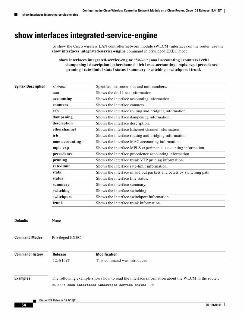
show interfaces integrated-service-engineTo show the Cisco wireless LAN controller network module (WLCM) interfaces on the router, use the show interfaces integrated-service-engine command in privileged EXEC mode.
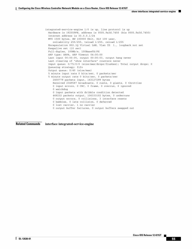
Examples The following example shows how to read the interface information about the WLCM in the router:
Router# show interfaces integrated-service-engine 1/0
slot/unit Specifies the router slot and unit numbers.
aaa Shows the dot11 aaa information.
accounting Shows the interface accounting information.
counters Shows the interface counters.
crb Shows the interface routing and bridging information.
dampening Shows the interface dampening information.
description Shows the interface description.
etherchannel Shows the interface Ethernet channel information.
irb Shows the interface routing and bridging information.
mac-accounting Shows the interface MAC accounting information.
mpls-exp Shows the interface MPLS experimental accounting information.
precedence Shows the interface precedence accounting information.
pruning Shows the interface trunk VTP pruning information.
rate-limit Shows the interface rate-limit information.
stats Shows the interface in and out packets and octets by switching path.
status Shows the interface line status.
summary Shows the interface summary.
switching Shows the interface switching.
switchport Shows the interface switchport information.
trunk Shows the interface trunk information.
Release Modification
12.4(15)T This command was introduced.
54Cisco IOS Release 12.4(15)T
OL-12630-01
Configuring the Cisco Wireless Controller Network Module on a Cisco Router, Cisco IOS Release 12.4(15)T show interfaces integrated-service-engine
integrated-service-engine 1/0 is up, line protocol is up Hardware is I82559FE, address is 0005.9a3d.7450 (bia 0005.9a3d.7450) Internet address is 30.0.0.1/24 MTU 1500 bytes, BW 100000 Kbit, DLY 100 usec, reliability 255/255, txload 1/255, rxload 1/255 Encapsulation 802.1Q Virtual LAN, Vlan ID 1., loopback not set Keepalive set (10 sec) Full-duplex, 100Mb/s, 100BaseTX/FX ARP type: ARPA, ARP Timeout 04:00:00 Last input 00:00:05, output 00:00:03, output hang never Last clearing of "show interface" counters never Input queue: 0/75/0/0 (size/max/drops/flushes); Total output drops: 0 Queueing strategy: fifo Output queue: 0/40 (size/max) 5 minute input rate 0 bits/sec, 0 packets/sec 5 minute output rate 0 bits/sec, 0 packets/sec 2400779 packets input, 143127299 bytes Received 2349587 broadcasts, 0 runts, 0 giants, 0 throttles 0 input errors, 0 CRC, 0 frame, 0 overrun, 0 ignored 0 watchdog 0 input packets with dribble condition detected 468232 packets output, 106333102 bytes, 0 underruns 0 output errors, 0 collisions, 3 interface resets 0 babbles, 0 late collision, 0 deferred 0 lost carrier, 1 no carrier 0 output buffer failures, 0 output buffers swapped out
Related Commands interface integrated-service-engine
55Cisco IOS Release 12.4(15)T
OL-12630-01
Configuring the Cisco Wireless Controller Network Module on a Cisco Router, Cisco IOS Release 12.4(15)T show interfaces integrated-service-engine
CCVP, the Cisco logo, and the Cisco Square Bridge logo are trademarks of Cisco Systems, Inc.; Changing the Way We Work, Live, Play, and Learnis a service mark of Cisco Systems, Inc.; and Access Registrar, Aironet, BPX, Catalyst, CCDA, CCDP, CCIE, CCIP, CCNA, CCNP, CCSP, Cisco,the Cisco Certified Internetwork Expert logo, Cisco IOS, Cisco Press, Cisco Systems, Cisco Systems Capital, the Cisco Systems logo, Cisco Unity,Enterprise/Solver, EtherChannel, EtherFast, EtherSwitch, Fast Step, Follow Me Browsing, FormShare, GigaDrive, HomeLink, Internet Quotient,IOS, iPhone, IP/TV, iQ Expertise, the iQ logo, iQ Net Readiness Scorecard, iQuick Study, LightStream, Linksys, MeetingPlace, MGX, NetworkingAcademy, Network Registrar, Packet, PIX, ProConnect, ScriptShare, SMARTnet, StackWise, The Fastest Way to Increase Your Internet Quotient,and TransPath are registered trademarks of Cisco Systems, Inc. and/or its affiliates in the United States and certain other countries.
All other trademarks mentioned in this document or Website are the property of their respective owners. The use of the word partner does not implya partnership relationship between Cisco and any other company. (0705R)
Any Internet Protocol (IP) addresses used in this document are not intended to be actual addresses. Any examples, command display output, andfigures included in the document are shown for illustrative purposes only. Any use of actual IP addresses in illustrative content is unintentional andcoincidental.