Configuring the DHCP Server On-Demand Address Pool Manager Last Updated: December 3, 2012 The Cisco IOS Dynamic Host Configuration Protocol (DHCP) server on-demand address pool (ODAP) manager is used to centralize the management of large pools of addresses and simplify the configuration of large networks. ODAP provides a central management point for the allocation and assignment of IP addresses. When a Cisco IOS router is configured as an ODAP manager, pools of IP addresses are dynamically increased or reduced in size depending on the address utilization level. A DHCP pool configured in the router can also be used as an IP address pooling mechanism. The IP address pooling mechanism is configured in the router to specify the source of IP addresses for PPP peers. • Finding Feature Information, page 1 • Prerequisites for Configuring the DHCP Server On-Demand Address Pool Manager, page 2 • Restrictions for Configuring the DHCP Server On-Demand Address Pool Manager, page 2 • Information About the DHCP Server On-Demand Address Pool Manager, page 2 • How to Configure the DHCP Server On-Demand Address Pool Manager, page 5 • Configuration Examples for DHCP Server On-Demand Address Pool Manager, page 28 • Additional References, page 35 • Feature Information for the DHCP Server On-Demand Address Pool Manager, page 37 • Glossary, page 38 Finding Feature Information Your software release may not support all the features documented in this module. For the latest caveats and feature information, see Bug Search Tool and the release notes for your platform and software release. To find information about the features documented in this module, and to see a list of the releases in which each feature is supported, see the feature information table at the end of this module. Use Cisco Feature Navigator to find information about platform support and Cisco software image support. To access Cisco Feature Navigator, go to www.cisco.com/go/cfn. An account on Cisco.com is not required. Americas Headquarters: Cisco Systems, Inc., 170 West Tasman Drive, San Jose, CA 95134-1706 USA
Transcript
Configuring the DHCP Server On-DemandAddress Pool Manager
Last Updated: December 3, 2012
The Cisco IOS Dynamic Host Configuration Protocol (DHCP) server on-demand address pool (ODAP)manager is used to centralize the management of large pools of addresses and simplify the configuration oflarge networks. ODAP provides a central management point for the allocation and assignment of IPaddresses. When a Cisco IOS router is configured as an ODAP manager, pools of IP addresses aredynamically increased or reduced in size depending on the address utilization level. A DHCP poolconfigured in the router can also be used as an IP address pooling mechanism. The IP address poolingmechanism is configured in the router to specify the source of IP addresses for PPP peers.
• Finding Feature Information, page 1• Prerequisites for Configuring the DHCP Server On-Demand Address Pool Manager, page 2• Restrictions for Configuring the DHCP Server On-Demand Address Pool Manager, page 2• Information About the DHCP Server On-Demand Address Pool Manager, page 2• How to Configure the DHCP Server On-Demand Address Pool Manager, page 5• Configuration Examples for DHCP Server On-Demand Address Pool Manager, page 28• Additional References, page 35• Feature Information for the DHCP Server On-Demand Address Pool Manager, page 37• Glossary, page 38
Finding Feature InformationYour software release may not support all the features documented in this module. For the latest caveatsand feature information, see Bug Search Tool and the release notes for your platform and software release.To find information about the features documented in this module, and to see a list of the releases in whicheach feature is supported, see the feature information table at the end of this module.
Use Cisco Feature Navigator to find information about platform support and Cisco software image support.To access Cisco Feature Navigator, go to www.cisco.com/go/cfn. An account on Cisco.com is not required.
Americas Headquarters:Cisco Systems, Inc., 170 West Tasman Drive, San Jose, CA 95134-1706 USA
Prerequisites for Configuring the DHCP Server On-DemandAddress Pool Manager
Before you configure the ODAP manager, you should understand the concepts documented in the “DHCPOverview” module.
You must configure standard Multiprotocol Label Switching (MPLS) Virtual Private Networks (VPNs)unless you intend to use non-MPLS VPNs.
In order for the IP address pooling mechanism to work correctly, the VPN routing and forwarding (VRF)instance of the PPP session must match that configured on the pool. Typically this matching is done eitherby configuring the ip vrf forwarding vrf-name command on the virtual template interface, or ifAuthentication, Authorization, and Accounting (AAA) is used to authorize the PPP user, the command canbe part of the user’s profile configuration.
Restrictions for Configuring the DHCP Server On-DemandAddress Pool Manager
• The ip dhcp excluded-address command available in global configuration mode cannot be used toexclude addresses from VRF-associated pools.
• The vrf command available in DHCP pool configuration mode is currently not supported for hostpools.
• Attribute inheritance is not supported on VRF pools.• A router can be configured as a subnet allocation server and a DHCP server at the same time with one
restriction: Separate pools must be created for subnet allocation and IP address assignment. An addresspool cannot be used by DHCP for both subnet allocation and IP address assignment.
Information About the DHCP Server On-Demand Address PoolManager
• ODAP Manager Operation, page 2• Subnet Allocation Server Operation, page 4• Benefits of Using ODAPs, page 5
ODAP Manager OperationODAPs enable pools of IP addresses to be dynamically increased or reduced in size depending on theaddress utilization level. Once configured, the ODAP is populated with one or more subnets leased from asource server and is ready to serve address requests from DHCP clients or from PPP sessions. The sourceserver can be a remote DHCP server or a RADIUS server (via AAA). Currently, only the Cisco AccessRegistrar RADIUS server supports ODAPs. Subnets can be added to the pool when a certain utilizationlevel (high utilization mark) is achieved. When the utilization level falls below a certain level (lowutilization mark), a subnet can be returned to the server from which it was originally leased. Summarized
ODAP Manager Operation Prerequisites for Configuring the DHCP Server On-Demand Address Pool Manager
2
routes for each leased subnet must be inserted or removed from the related VRF with each addition orremoval of subnets into the ODAP.
ODAPs support address assignment using DHCP for customers using private addresses such as in MPLSVPNs. VPNs allow the possibility that two pools in separate networks can have the same address space,with private network addresses, served by the same DHCP server. These IP addresses can be distinguishedby a VPN identifier to help select the VPN to which the client belongs.
Each ODAP is configured and associated with a particular MPLS VPN. Cisco IOS software also supportsnon-MPLS VPN address pools by adding pool name support to the peer default ip address dhcp-poolpool-namecommand.
For MPLS VPNs, each VPN is associated with one or more VRFs. The VRF is a key element in the VPNtechnology because it maintains the routing information that defines a customer VPN site. This customersite is attached to a provider edge (PE) router. A VRF consists of an IP routing table, a derived CiscoExpress Forwarding table, a set of interfaces that use the forwarding table, and a set of rules and routingprotocol parameters that control the information that is included in the routing table.
A PPP session belonging to a specific VPN is allocated an address only from the ODAP associated withthat VPN. These PPP sessions are terminated on a Virtual Home Gateway (VHG)/PE router where theODAP is configured. The VHG/PE router maps the remote user to the corresponding MPLS VPNs.
For PPP sessions, individual address allocation from an ODAP follows a First Leased subnet First (FLF)policy. FLF searches for a free address beginning on the first leased subnet, followed by a search on thesecond leased subnet if no free address is available in the first subnet, and so on. This policy provides thebenefit of grouping the leased addresses over time to a set of subnets, which allows an efficient subnetrelease and route summarization.
However, the FLF policy differs from the normal DHCP address selection policy. Normal DHCP addressselection considers the IP address of the receiving interface or the gateway address if it is nonzero. Tosupport both policies, the DHCP server needs to be able to distinguish between a normal DHCP addressrequest and an address request for a PPP client. The ODAP manager uses an IP address pooling mechanismfor PPP that allows the DHCP server to distinguish between a normal DHCP address request and a requestfrom a PPP client.
Subnet release from an ODAP follows a Last Leased subnet First (LLF) policy, which prefers the lastleased subnet to be released first. This LLF policy searches for a releasable subnet (a subnet with noaddresses currently being leased) starting with the last leased subnet. If a releasable subnet is found(candidate subnet), it is released, and the summarized route for that subnet is removed. If more than onereleasable subnet exists at that time, only the most recently allocated is released. If there are no releasablesubnets, no action is taken. If by releasing the candidate subnet, the high utilization mark is reached, thesubnet is not released. The first leased subnet is never released (regardless of the instantaneous utilizationlevel) until the ODAP is disabled.
When a DHCP pool receives multiple subnets from an upstream DHCP server, an address from each subnetis automatically configured on the client connected interface so that the addresses within the subnets can berequested by DHCP clients.
The first address in the first subnet is automatically assigned to the primary address on the interface. Thefirst address of each subsequent subnet is assigned to secondary addresses on the interface. In addition, asclient addresses are reclaimed, the count of lease addresses for that subnet is decremented. Once a leasecounter for a subnet reaches zero (that is, lease expiry), the subnet is returned to the pool. The previousaddress on the interface is removed and the first secondary address on the interface is promoted as theprimary address of the interface.
The figure below shows an ODAP manager configured on the Cisco IOS DHCP server. The ODAPrequests an initial pool from the AAA server. Clients make DHCP requests and the DHCP server fulfillsrequests from the pool. When the utilization rate meets 90 percent, the ODAP manager requests an
ODAP Manager OperationInformation About the DHCP Server On-Demand Address Pool Manager
3
expansion and the AAA server allocates another subnet from which the ODAP manager can allocateaddresses.
Figure 1 ODAP Address Pool Management for MPLS VPNs
127106
DHCP client 1 in "green"
VPN blue/10.88.1.128/25
10.88.1.128/25 10.88.1.0/25
AAA server
DHCP client 2 in "red"
VPN blue/192.168.1.0/24VPN red/10.88.1.128/25 Cisco IOS DHCP server
Use 10.88.1.0/25
DHCP request
Subnet Allocation Server OperationYou can configure the ODAP manager to allocate subnets instead of individual IP addresses.
This capability allows the network operator to configure a Cisco IOS router as a subnet allocation server.The operation of a subnet allocation server is similar to the operation of a DHCP server, except that poolsof subnets are created and assigned instead of pools of IP addresses. Subnet allocation pools are created andconfigured by using the subnet prefix-length command in DHCP pool configuration mode. The size ofeach assigned or allocated subnet is set by the prefix-length argument, using standard Common InterdomainRouting (CIDR) bit count notation to determine the number of addresses that are configured in each subnetlease.
When a DHCP server is configured as a subnet allocation server, it provides subnet allocation pools forODAP manager allocation. In the figure below, Router B is the subnet allocation server and allocatessubnets to the ODAP manager based on the demand for IP addresses and subnet availability. Router B isconfigured to allocate an initial amount of address space in the form of subnets to the ODAP manager. Thesize of the subnet allocated by the ODAP manager is determined by the subnet size that is configured onthe subnet allocation server. The ODAP manager will then assign addresses to clients from these subnetsand allocate more subnets as the need for address space increases.
Figure 2 Subnet Allocation Server Topology
12
71
05
PPP remote peer Router A ODAP manager
Router B Subnet allocation
server
When the ODAP manager allocates a subnet, the subnet allocation server creates a subnet binding. Thisbinding is stored in the DHCP database for as long as the ODAP manager requires the address space. Thebinding is removed and the subnet is returned to the subnet pool only when the ODAP manager releases thesubnet as address space utilization decreases.
Subnet Allocation Server Operation Information About the DHCP Server On-Demand Address Pool Manager
4
The subnet allocation server can also be associated with a VRF. A VRF consists of an IP routing table, aderived Cisco Express Forwarding table, a set of interfaces that use the forwarding table, and a set of rulesand routing protocol parameters that control the information that is included in the routing table.
Benefits of Using ODAPs
Efficient Address Management
The ODAP manager allows customers to optimize their use of IP addresses, thus conserving address space.
Efficient Route Summarization and Update
The ODAP manager inserts a summarized route when a subnet is added to the ODAP.
Multiple VRF and Independent Private Addressing Support
The ODAP manager automatically injects subnet routing information into the appropriate VRF.
How to Configure the DHCP Server On-Demand Address PoolManager
• Specifying DHCP ODAPs as the Global Default Mechanism, page 5• Defining DHCP ODAPs on an Interface, page 6• Configuring the DHCP Pool as an ODAP, page 7• Configuring ODAPs to Obtain Subnets Through IPCP Negotiation, page 9• Configuring AAA, page 11• Configuring RADIUS, page 13• Disabling ODAPs, page 15• Verifying ODAP Operation, page 16• Monitoring and Maintaining the ODAP, page 18• Configuring DHCP ODAP Subnet Allocation Server Support, page 20
Specifying DHCP ODAPs as the Global Default MechanismPerform this task to specify that the global default mechanism to use is on-demand address pooling.
IP addressing allows configuration of a global default address pooling mechanism. The DHCP server needsto be able to distinguish between a normal DHCP address request and an address request for a PPP client.
SUMMARY STEPS
1. enable
2. configure terminal
3. ip address-pool dhcp-pool
Benefits of Using ODAPsHow to Configure the DHCP Server On-Demand Address Pool Manager
5
DETAILED STEPS
Command or Action Purpose
Step 1 enable
Example:
Router> enable
Enables privileged EXEC mode.
• Enter your password if prompted.
Step 2 configure terminal
Example:
Router# configure terminal
Enters global configuration mode.
Step 3 ip address-pool dhcp-pool
Example:
Router(config)# ip address-pool dhcp-pool
Specifies on-demand address pooling as the global default IP addressmechanism.
• For remote access (PPP) sessions into MPLS VPNs, IP addresses areobtained from locally configured VRF-associated DHCP pools.
Note You must use two separate DHCP address pools for globalconfiguration mode and VRF mode. If you change a globalconfiguration pool to VRF mode, then all the IP addresses in the globalpool will be lost. Hence make sure that you have a VRF pool for aninterface in order to add an interface under a VRF.
Defining DHCP ODAPs on an InterfacePerform this task to define on-demand address pools on an interface.
The interface on-demand address pooling configuration overrides the global default mechanism on thatinterface.
SUMMARY STEPS
1. enable
2. configure terminal
3. interface type number
4. peer default ip address dhcp-pool [pool-name]
Defining DHCP ODAPs on an Interface How to Configure the DHCP Server On-Demand Address Pool Manager
6
DETAILED STEPS
Command or Action Purpose
Step 1 enable
Example:
Router> enable
Enables privileged EXEC mode.
• Enter your password if prompted.
Step 2 configure terminal
Example:
Router# configure terminal
Enters global configuration mode.
Step 3 interface type number
Example:
Router(config)# interface Virtual-Template 1
Specifies the interface and enters interface configuration mode.
Step 4 peer default ip address dhcp-pool [pool-name]
Example:
Router(config)# peer default ip address dhcp-pool mypool
Specifies an IP address from an on-demand address pool to bereturned to a remote peer connecting to this interface.
• The pool-name argument supports non-MPLS VPNs and ismandatory if the session is not associated with any VRF.Multiple pool names can be accepted but must be separated byblank spaces.
Configuring the DHCP Pool as an ODAPPerform this task to configure a DHCP address pool as an ODAP pool.
Configures an address pool as an on-demand address pool.
• If you do not configure the pool as an autogrow pool, the pool will not requestadditional subnets if one subnet is already in the pool.
• You can enter size as either the subnet mask (nnnn.nnnn.nnnn.nnnn) or prefixsize (/nn). The valid values are /0 and /4 to /30.
• When a DHCP pool receives multiple subnets from an upstream DHCPserver, an address from each subnet is automatically configured on the clientconnected interface so that the addresses within the subnets can be requestedby DHCP clients. The first address in the first subnet is automaticallyassigned to the primary address on the interface. The first address of eachsubsequent subnet is assigned to secondary addresses on the interface. Inaddition, as client addresses are reclaimed, the count of lease addresses forthat subnet is decremented. Once a lease counter for a subnet reaches zero(that is, lease expiry), the subnet is returned to the pool. The previous addresson the interface is removed and the first secondary address on the interface ispromoted as the primary address of the interface.
• If the origin aaa option is configured, AAA must be configured.
Configuring the DHCP Pool as an ODAP How to Configure the DHCP Server On-Demand Address Pool Manager
8
Command or Action Purpose
Step 6 utilization mark low percentage-number
Example:
Router(dhcp-config)# utilization mark low 40
Sets the low utilization mark of the pool size.
• This command cannot be used unless the autogrow size option of the origincommand is configured.
• The default value is 0 percent.
Step 7 utilization mark high percentage-number
Example:
Router(dhcp-config)# utilization mark high 60
Sets the high utilization mark of the pool size.
• This command cannot be used unless the autogrow size option of the origincommand is configured.
• The default value is 100 percent.
Step 8 end
Example:
Router(dhcp-config)# end
Returns to previleged EXEC mode.
Step 9 show ip dhcp pool [pool-name]
Example:
Router# show ip dhcp pool
(Optional) Displays information about DHCP address pools.
• Information about the primary and secondary interface address assignment isalso displayed.
Configuring ODAPs to Obtain Subnets Through IPCP NegotiationPerform this task to configure ODAPs to use subnets obtained through IP Control Protocol (IPCP)negotiation.
You can assign IP address pools to customer premises equipment (CPE) devices, which, in turn, assign IPaddresses to the CPE and to a DHCP pool. This functionality has three requirements:
• The Cisco IOS CPE device must be able to request and use the subnet.• The RADIUS server (via AAA) must be able to provide that subnet and insert the framed route into
the proper VRF table.• The PE router must be able to facilitate providing the subnet through (IPCP) negotiation.
Configuring ODAPs to Obtain Subnets Through IPCP NegotiationHow to Configure the DHCP Server On-Demand Address Pool Manager
9
SUMMARY STEPS
1. enable
2. configure terminal
3. ip dhcp pool pool-name
4. import all
5. origin ipcp
6. exit
7. interface type number
8. ip address pool pool-name
DETAILED STEPS
Command or Action Purpose
Step 1 enable
Example:
Router> enable
Enables privileged EXEC mode.
• Enter your password if prompted.
Step 2 configure terminal
Example:
Router# configure terminal
Enters global configuration mode.
Step 3 ip dhcp pool pool-name
Example:
Router(config)# ip dhcp pool red-pool
Configures a DHCP address pool on a Cisco IOS DHCP server andenters DHCP pool configuration mode.
Step 4 import all
Example:
Router(dhcp-config)# import all
Imports option parameters into the Cisco IOS DHCP serverdatabase.
Step 5 origin ipcp
Example:
Router(dhcp-config)# origin ipcp
Configures an address pool as an on-demand address pool usingIPCP as the subnet allocation protocol.
Configuring ODAPs to Obtain Subnets Through IPCP Negotiation How to Configure the DHCP Server On-Demand Address Pool Manager
10
Command or Action Purpose
Step 6 exit
Example:
Router(dhcp-config)# exit
Exits DHCP pool configuration mode.
Step 7 interface type number
Example:
Router(config)# interface ethernet 0
Specifies the interface and enters interface configuration mode.
Step 8 ip address pool pool-name
Example:
Router(config-if)# ip address pool red-pool
Specifies that the interface IP address will be automaticallyconfigured from the named pool, when the pool is populated with asubnet from IPCP.
Configuring AAATo allow ODAP to obtain subnets from the AAA server, the AAA client must be configured on theVHG/PE router.
SUMMARY STEPS
1. enable
2. configure terminal
3. aaa new-model
4. aaa authorization configuration default group radius
5. aaa accounting network default start-stop group radius
6. aaa session-id common
DETAILED STEPS
Command or Action Purpose
Step 1 enable
Example:
Router> enable
Enables privileged EXEC mode.
• Enter your password if prompted.
Configuring AAAHow to Configure the DHCP Server On-Demand Address Pool Manager
11
Command or Action Purpose
Step 2 configure terminal
Example:
Router# configure terminal
Enters global configuration mode.
Step 3 aaa new-model
Example:
Router(config)# aaa new-model
Enables AAA access control.
Step 4 aaa authorization configuration default group radius
Example:
Router(config)# aaa authorization configuration default group radius
Downloads static route configuration information fromthe AAA server using RADIUS.
Configuring AAA How to Configure the DHCP Server On-Demand Address Pool Manager
12
Command or Action Purpose
Step 5 aaa accounting network default start-stop group radius
Example:
or
Example:
aaa accounting network default stop-only group radius
Example:
Router(config)# aaa accounting network default start-stop group radius
Example:
or
Example:
Example:
Router(config)# aaa accounting network default stop-only group radius
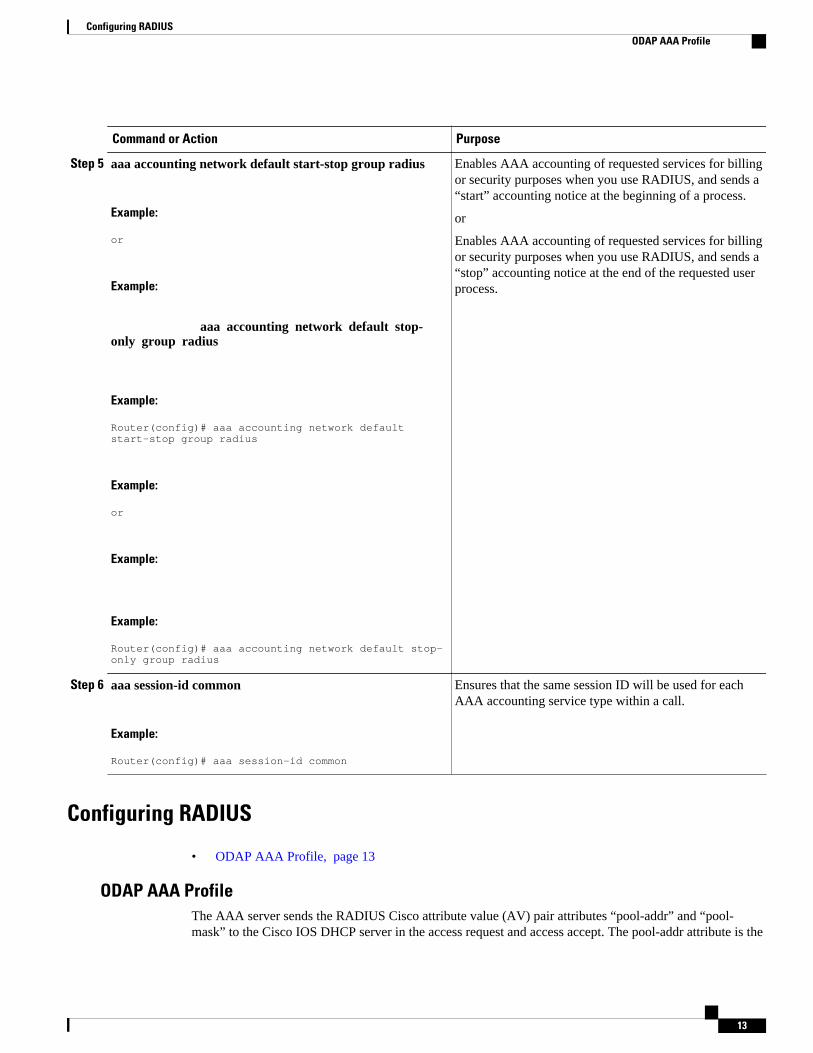
Enables AAA accounting of requested services for billingor security purposes when you use RADIUS, and sends a“start” accounting notice at the beginning of a process.
or
Enables AAA accounting of requested services for billingor security purposes when you use RADIUS, and sends a“stop” accounting notice at the end of the requested userprocess.
Step 6 aaa session-id common
Example:
Router(config)# aaa session-id common
Ensures that the same session ID will be used for eachAAA accounting service type within a call.
Configuring RADIUS
• ODAP AAA Profile, page 13
ODAP AAA ProfileThe AAA server sends the RADIUS Cisco attribute value (AV) pair attributes “pool-addr” and “pool-mask” to the Cisco IOS DHCP server in the access request and access accept. The pool-addr attribute is the
Configuring RADIUSODAP AAA Profile
13
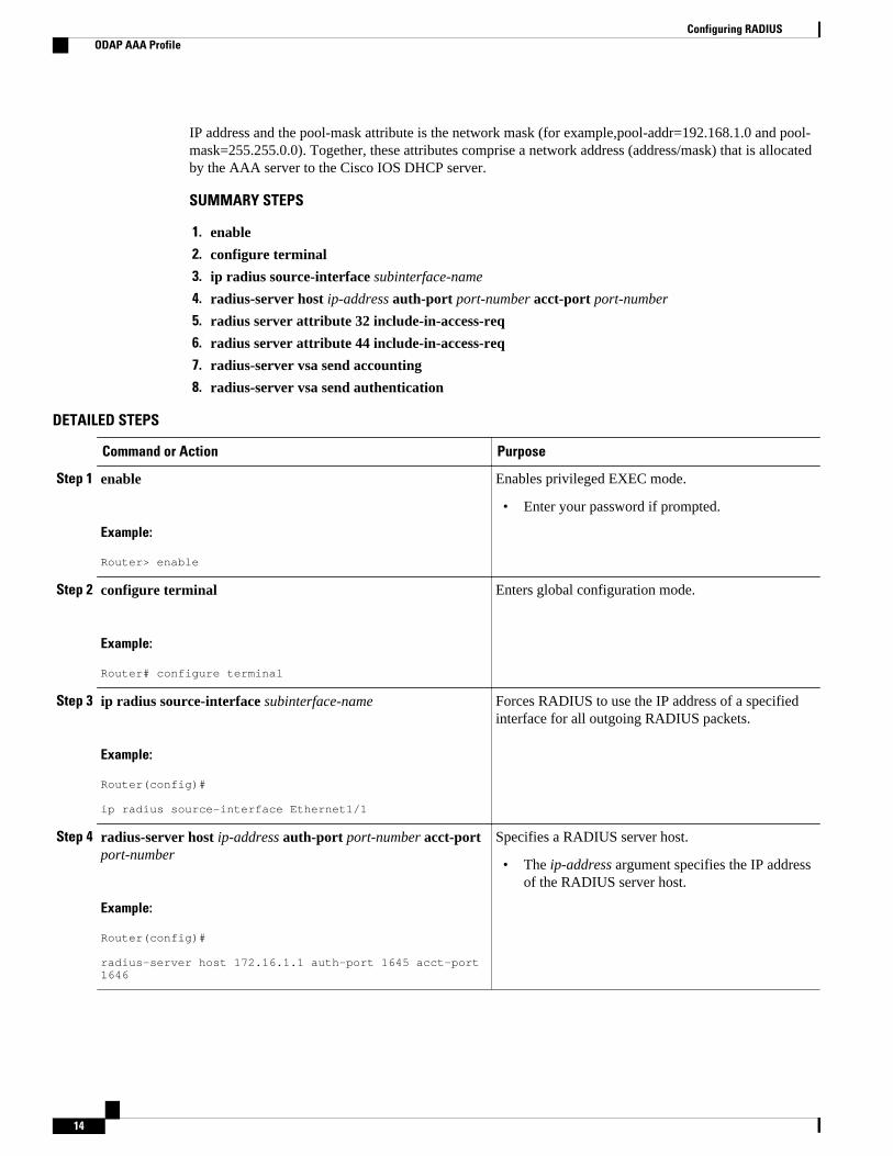
IP address and the pool-mask attribute is the network mask (for example,pool-addr=192.168.1.0 and pool-mask=255.255.0.0). Together, these attributes comprise a network address (address/mask) that is allocatedby the AAA server to the Cisco IOS DHCP server.
• The ip-address argument specifies the IP addressof the RADIUS server host.
Configuring RADIUS ODAP AAA Profile
14
Command or Action Purpose
Step 5 radius server attribute 32 include-in-access-req
Example:
Router(config)# radius server attribute 32 include-in-access-req
Sends RADIUS attribute 32 (NAS-Identifier) in anaccess request or accounting request.
Step 6 radius server attribute 44 include-in-access-req
Example:
Router(config)# radius server attribute 44 include-in-access-req
Sends RADIUS attribute 44 (Accounting Session ID)in an access request or accounting request.
Step 7 radius-server vsa send accounting
Example:
Router(config)# radius-server vsa send accounting
Configures the network access server (NAS) torecognize and use vendor-specific accountingattributes.
Step 8 radius-server vsa send authentication
Example:
Router(config)# radius-server vsa send authentication
Configures the NAS to recognize and use vendor-specific authentication attributes.
Disabling ODAPsThis task shows how to disable an ODAP from a DHCP pool.
When an ODAP is disabled, all leased subnets are released. If active PPP sessions are using addresses fromthe released subnets, those sessions will be reset. DHCP clients leasing addresses from the released subnetswill not be able to renew their leases.
SUMMARY STEPS
1. enable
2. configure terminal
3. ip dhcp pool pool-name
4. no origin {dhcp | aaa | ipcp}
Disabling ODAPsODAP AAA Profile
15
DETAILED STEPS
Command or Action Purpose
Step 1 enable
Example:
Router> enable
Enables privileged EXEC mode.
• Enter your password if prompted.
Step 2 configure terminal
Example:
Router# configure terminal
Enters global configuration mode.
Step 3 ip dhcp pool pool-name
Example:
Router(config)# ip dhcp pool pool1
Configures a DHCP address pool on a Cisco IOS DHCP server and entersDHCP pool configuration mode.
Step 4 no origin {dhcp | aaa | ipcp}
Example:
Router(dhcp-config)# no origin dhcp
Disables the ODAP.
Verifying ODAP Operation
SUMMARY STEPS
1. enable
2. show ip dhcp binding The following output shows the bindings from pool Green. The Type fieldshows On-demand, which indicates that the address binding was created for a PPP session. The Leaseexpiration field shows Infinite, which means that the binding is valid as long as the session is up. If asubnet must be released back to the leasing server while the session is still up, the session is reset so thatit will be forced to obtain a new IP address. The Hardware address column for an On-demand entryshows the identifier for the session as detected by PPP. No bindings are shown under the Bindings fromall pools not associated with VRF field because the Global pool has not allocated any addresses.
DETAILED STEPS
Step 1 enableEnables privileged EXEC mode. Enter your password if prompted.
Verifying ODAP Operation ODAP AAA Profile
16
Example:
Router> enable
show ip dhcp pool [pool-name] The following output is for two DHCP pools: Green and Global. Pool Green isconfigured with a high utilization mark of 50 and a low utilization mark of 30. The pool is also configured to obtainmore subnets when the high utilization mark is reached (autogrow). The Subnet size field indicates the valuesconfigured in the origin command as the initial and incremental subnet sizes that would be requested by the poolnamed Green. The Total addresses field is a count of all the usable addresses in the pool. The Leased addresses field isa total count of how many bindings were created from the pool. The Pending event field shows subnet request, whichmeans that a subnet request is pending for the pool. The subnet request was scheduled because the Leased addressescount has exceeded the high utilization level of the pool. Subnets currently added to pool Green are shown insequence. The Current index column shows the address that would be allocated next from this subnet. The IP addressrange column shows the range of usable addresses from the subnet. The Leased addresses column shows individualcount of bindings created from each subnet. Three subnets are currently added to pool Green. The first two subnetshave used all their addresses and thus the Current index is showing 0.0.0.0. Notice that pool Green and pool Globalcan have the same subnet (172.16.0.1-172.16.0.6) because pool Green is configured to be in VRF Green, and poolGlobal is configured to be in the global address space.
Example:
Router# show ip dhcp pool Pool Green : Utilization mark (high/low) : 50 / 30 Subnet size (first/next) : 24 / 24 (autogrow) VRF name : Green Total addresses : 18 Leased addresses : 13 Pending event : subnet request 3 subnets are currently in the pool : Current index IP address range Leased addresses 0.0.0.0 172.16.0.1 - 172.16.0.6 6 0.0.0.0 172.16.0.9 - 172.16.0.14 6 172.16.0.18 172.16.0.17 - 172.16.0.22 1Pool Global : Utilization mark (high/low) : 100 / 0 Subnet size (first/next) : 24 / 24 (autogrow) Total addresses : 6 Leased addresses : 0 Pending event : none 1 subnet is currently in the pool : Current index IP address range Leased addresses 172.16.0.1 172.16.0.1 - 172.16.0.6 0
Step 2 show ip dhcp binding The following output shows the bindings from pool Green. The Type field shows On-demand,which indicates that the address binding was created for a PPP session. The Lease expiration field shows Infinite,which means that the binding is valid as long as the session is up. If a subnet must be released back to the leasingserver while the session is still up, the session is reset so that it will be forced to obtain a new IP address. TheHardware address column for an On-demand entry shows the identifier for the session as detected by PPP. Nobindings are shown under the Bindings from all pools not associated with VRF field because the Global pool has notallocated any addresses.
Example:
Router# show ip dhcp binding
Bindings from all pools not associated with VRF:IP address Hardware address Lease expiration TypeBindings from VRF pool Green:
Troubleshooting TipsBy default, the Cisco IOS DHCP server on which the ODAP manager is based attempts to verify an addressavailability by performing a ping operation to the address before allocation. The default DHCP pingconfiguration will wait for 2 seconds for an Internet Control Message Protocol (ICMP) echo reply. Thisdefault configuration results in the DHCP server servicing one address request every 2 seconds. Thenumber of ping packets being sent and the ping timeout are configurable. Thus, to reduce the addressallocation time, you can reduce either the timeout or the number of ping packets sent. Reducing the timeoutor the ping packets being sent will improve the address allocation time, at the cost of less ability to detectduplicate addresses.
Each ODAP will make a finite number of attempts (up to four retries) to obtain a subnet from DHCP orAAA. If these attempts are not successful, the subnet request from the pool automatically starts when thereis another individual address request to the pool (for example, from a newly brought up PPP session). If apool has not been allocated any subnets, you can force restarting the subnet request process by using theclear ip dhcp pool pool-name subnet * command.
Monitoring and Maintaining the ODAPThis task shows how to monitor and maintain the ODAP. These commands need not be entered in anyspecific order.
Note the following behavior for the clear ip dhcp binding, clear ip dhcp conflict, and clear ip dhcpsubnet commands:
Monitoring and Maintaining the ODAP Troubleshooting Tips
18
• If you do not specify the pool pool-name option and an IP address is specified, it is assumed that theIP address is an address in the global address space and will look among all the non-VRF DHCP poolsfor the specified binding/conflict/subnet.
• If you do not specify the pool pool-name option and the * option is specified, it is assumed that allautomatic/ or on-demand bindings/conflicts/subnets in all VRF and non-VRF pools are to be deleted.
• If you specify both the pool pool-name option and the * option, all automatic or on-demand bindings/conflicts/subnets in the specified pool only will be cleared.
• If you specify the pool pool-name option and an IP address, the specified binding/conflict or thesubnet containing the specified IP address will be deleted from the specified pool.
SUMMARY STEPS
1. enable
2. clear ip dhcp [pool pool-name] binding {* | address}
3. clear ip dhcp [pool pool-name] conflict {* | address}
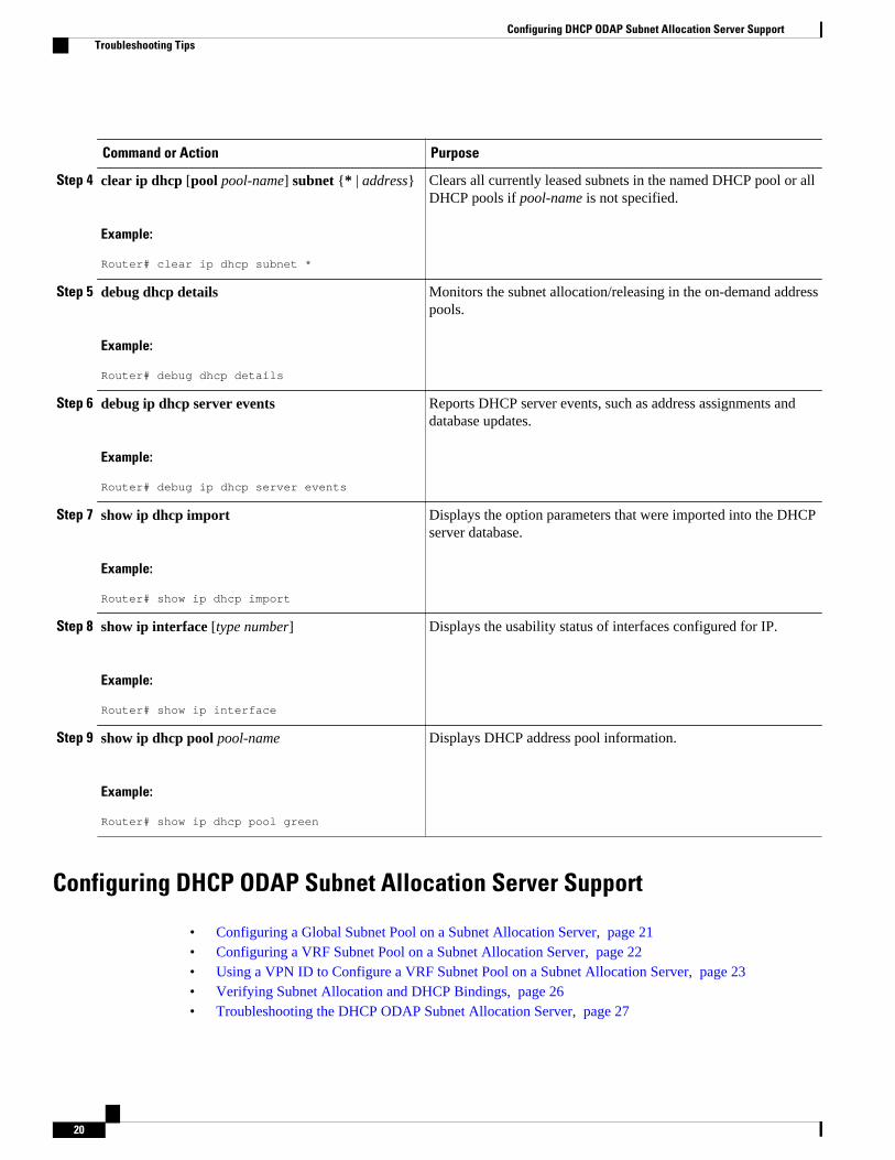
4. clear ip dhcp [pool pool-name] subnet {* | address}
Clears all currently leased subnets in the named DHCP pool or allDHCP pools if pool-name is not specified.
Step 5 debug dhcp details
Example:
Router# debug dhcp details
Monitors the subnet allocation/releasing in the on-demand addresspools.
Step 6 debug ip dhcp server events
Example:
Router# debug ip dhcp server events
Reports DHCP server events, such as address assignments anddatabase updates.
Step 7 show ip dhcp import
Example:
Router# show ip dhcp import
Displays the option parameters that were imported into the DHCPserver database.
Step 8 show ip interface [type number]
Example:
Router# show ip interface
Displays the usability status of interfaces configured for IP.
Step 9 show ip dhcp pool pool-name
Example:
Router# show ip dhcp pool green
Displays DHCP address pool information.
Configuring DHCP ODAP Subnet Allocation Server Support
• Configuring a Global Subnet Pool on a Subnet Allocation Server, page 21• Configuring a VRF Subnet Pool on a Subnet Allocation Server, page 22• Using a VPN ID to Configure a VRF Subnet Pool on a Subnet Allocation Server, page 23• Verifying Subnet Allocation and DHCP Bindings, page 26• Troubleshooting the DHCP ODAP Subnet Allocation Server, page 27
Configuring DHCP ODAP Subnet Allocation Server Support Troubleshooting Tips
20
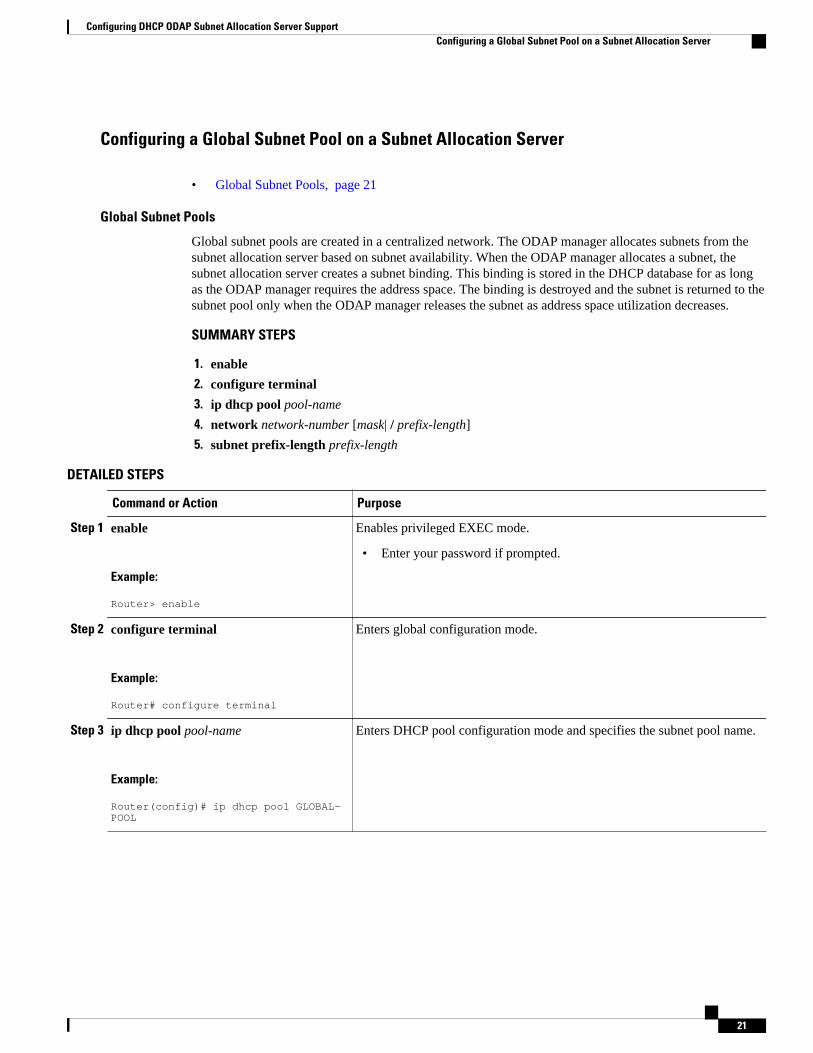
Configuring a Global Subnet Pool on a Subnet Allocation Server
• Global Subnet Pools, page 21
Global Subnet Pools
Global subnet pools are created in a centralized network. The ODAP manager allocates subnets from thesubnet allocation server based on subnet availability. When the ODAP manager allocates a subnet, thesubnet allocation server creates a subnet binding. This binding is stored in the DHCP database for as longas the ODAP manager requires the address space. The binding is destroyed and the subnet is returned to thesubnet pool only when the ODAP manager releases the subnet as address space utilization decreases.
SUMMARY STEPS
1. enable
2. configure terminal
3. ip dhcp pool pool-name
4. network network-number [mask| / prefix-length]
5. subnet prefix-length prefix-length
DETAILED STEPS
Command or Action Purpose
Step 1 enable
Example:
Router> enable
Enables privileged EXEC mode.
• Enter your password if prompted.
Step 2 configure terminal
Example:
Router# configure terminal
Enters global configuration mode.
Step 3 ip dhcp pool pool-name
Example:
Router(config)# ip dhcp pool GLOBAL-POOL
Enters DHCP pool configuration mode and specifies the subnet pool name.
Configuring DHCP ODAP Subnet Allocation Server SupportConfiguring a Global Subnet Pool on a Subnet Allocation Server
Configures the subnet number and mask for a DHCP address pool on aCisco IOS DHCP server.
• The subnet mask or the prefix length can be configured in this step.The values that can be configured for the prefix-length argumentfollow CIDR bit count notation. The forward slash character must beused when configuring the prefix-length argument.
Step 5 subnet prefix-length prefix-length
Example:
Router(dhcp-config)# subnet prefix-length 8
Configures the subnet prefix length. The range of the prefix-lengthargument is from 1 to 31.
• This command configures the number of IP addresses that each subnetis configured to allocate from the subnet pool. The values that can beconfigured for the prefix-length argument follow CIDR bit countnotation format.
Configuring a VRF Subnet Pool on a Subnet Allocation Server
• VRF Subnet Pools, page 22
VRF Subnet Pools
A subnet allocation server can be configured to assign subnets from VRF subnet allocation pools for MPLSVPN clients. VPN routes between the ODAP manager and the subnet allocation server are configuredbased on the VRF name or VPN ID configuration. The VRF and VPN ID are configured to maintainrouting information that defines customer VPN sites. The VPN customer site (or customer equipment [CE])is attached to a PE router. The VRF is used to specify the VPN and consists of an IP routing table, aderived Cisco Express Forwarding table, a set of interfaces that use the forwarding table, and a set of rulesand routing protocol parameters that control the information that is included in the routing table.
The VRF name and VPN ID can be configured on the ODAP manager and subnet allocation server prior tothe configuration of the subnet allocation pool.
SUMMARY STEPS
1. enable
2. configure terminal
3. ip dhcp pool pool-name
4. vrf vrf-name
5. network network-number [mask |/ prefix-length]
6. subnet prefix-length prefix-length
Configuring DHCP ODAP Subnet Allocation Server Support Configuring a VRF Subnet Pool on a Subnet Allocation Server
22
DETAILED STEPS
Command or Action Purpose
Step 1 enable
Example:
Router> enable
Enables privileged EXEC mode.
• Enter your password if prompted.
Step 2 configure terminal
Example:
Router# configure terminal
Enters global configuration mode.
Step 3 ip dhcp pool pool-name
Example:
Router(config)# ip dhcp pool VRF-POOL
Enters DHCP pool configuration mode and specifies the subnet pool name.
Step 4 vrf vrf-name
Example:
Router(dhcp-config)# vrf vrf1
Associates the on-demand address pool with a VRF instance name (or tag).
• The vrfcommand and vrf-name argument are used to specify the VPN forthe VRF pool. The vrf-nameargument must match the VRF name (or tag)that is configured for the client.
Configures the subnet number and mask for a DHCP address pool on a CiscoIOS DHCP server.
• The subnet mask or the prefix length can be configured in this step. Thevalues that can be configured for the prefix-length argument follow CIDRbit count notation. The forward slash character must be used whenconfiguring the prefix-lengthargument.
Step 6 subnet prefix-length prefix-length
Example:
Router(dhcp-config)# subnet prefix-length 16
Configures the subnet prefix length.
• The range of the prefix-lengthargument is from 1 to 31.• This command configures the number of IP addresses that each subnet is
configured to allocate from the subnet pool. The values that can beconfigured for the prefix-lengthargument follow CIDR bit count notationformat.
Using a VPN ID to Configure a VRF Subnet Pool on a Subnet Allocation ServerPerform this task to configure a VRF subnet pool, using a VPN ID, on a subnet allocation server.
• VRF Pools and VPN IDs, page 24
Configuring DHCP ODAP Subnet Allocation Server SupportUsing a VPN ID to Configure a VRF Subnet Pool on a Subnet Allocation Server
23
VRF Pools and VPN IDs
A subnet allocation server can be configured to assign subnets from VPN subnet allocation pools based onthe VPN ID of a client. The VPN ID (or Organizational Unique Identifier [OUI]) is a unique identifierassigned by the IEEE.
The VRF name and VPN ID can be configured on the ODAP manager and subnet allocation server prior tothe configuration of the subnet allocation pool.
SUMMARY STEPS
1. enable
2. configure terminal
3. ip vrf vrf-name
4. rd route-distinguisher
5. route-target both route-target-number
6. vpn id vpn-id
7. exit
8. ip dhcp pool pool-name
9. vrf vrf-name
10. network network-number [mask|/ prefix-length]
11. subnet prefix-length prefix-length
DETAILED STEPS
Command or Action Purpose
Step 1 enable
Example:
Router> enable
Enables privileged EXEC mode.
• Enter your password if prompted.
Step 2 configure terminal
Example:
Router# configure terminal
Enters global configuration mode.
Step 3 ip vrf vrf-name
Example:
Router(config)# ip vrf vrf1
Creates a VRF routing table and specifies the VRF name (or tag).
• The vrf-name argument must match the VRF name that is configured for theclient and VRF pool in Step 9.
Configuring DHCP ODAP Subnet Allocation Server Support VRF Pools and VPN IDs
24
Command or Action Purpose
Step 4 rd route-distinguisher
Example:
Router(config-vrf)# rd 100:1
Creates routing and forwarding tables for a VRF instance created in Step 3.
• There are two formats for configuring the route distinguisher argument. Itcan be configured in the as-number:network number (ASN:nn) format, asshown in the example, or it can be configured in the IP address:networknumber format (IP-address:nn).
Step 5 route-target both route-target-number
Example:
Router(config-vrf)# route-target both 100:1
Creates a route-target extended community for the VRF instance that was createdin Step 3.
• The bothkeyword is used to specify which routes should be imported andexported to the target VPN extended community (or the ODAP manager inthis configuration).
• The route-target-numberargument follows the same format as the route-distinguisherargument in Step 4. These two arguments must match.
Step 6 vpn id vpn-id
Example:
Router(config-vrf)# vpn id 1234:123456
Configures the VPN ID.
• This command is used only if the client (ODAP manager) is also configuredwith or assigned a VPN ID.
Step 7 exit
Example:
Router(config-vrf)# exit
Exits VRF configuration mode and enters global configuration mode.
Step 8 ip dhcp pool pool-name
Example:
Router(config)# ip dhcp pool VPN-POOL
Enters DHCP pool configuration mode and specifies the subnet pool name.
• The vrfkeyword and vrf-nameargument are used to specify the VPN for theVRF pool. The vrf-nameargument must match the VRF name (or tag) that isconfigured for the client.
Step 9 vrf vrf-name
Example:
Router(dhcp-config)#vrf RED
Associates the on-demand address pool with a VRF instance name.
• The vrf-name argument must match the vrf-nameargument that wasconfigured in Step 3.
Configuring DHCP ODAP Subnet Allocation Server SupportVRF Pools and VPN IDs
Configures the subnet number and mask for a DHCP address pool on a Cisco IOSDHCP server.
• The subnet mask or the prefix length can be configured in this step. Thevalues that can be configured for the prefix-lengthargument follow CIDR bitcount notation. The forward slash character must be used when configuringthe prefix-lengthargument.
Step 11 subnet prefix-length prefix-length
Example:
Router(dhcp-config)# subnet prefix-length 16
Configures the subnet prefix length.
• The range of the prefix-length argument is from 1 to 31.• This command configures the number of IP addresses that each subnet is
configured to allocate from the subnet pool. The values that can beconfigured for the prefix-lengthargument follow CIDR bit count notationformat.
Verifying Subnet Allocation and DHCP BindingsPerform this task to verify subnet allocation and DHCP bindings. The showcommands need not be enteredin any specific order.
The show ip dhcp pool and show ip dhcp bindingcommands need not be issued together or even in thesame session because there are differences in the information that is provided. These commands, however,can be used to display and verify subnet allocation and DHCP bindings. The show running-config | begindhcp command is used to display the local configuration of DHCP and the configuration of the subnetprefix-length command.
SUMMARY STEPS
1. enable
2. show running-config | begin dhcp
3. show ip dhcp pool [pool-name]
4. show ip dhcp binding [ip-address]
DETAILED STEPS
Command or Action Purpose
Step 1 enable
Example:
Router> enable
Enables privileged EXEC mode.
• Enter your password if prompted.
Configuring DHCP ODAP Subnet Allocation Server Support Verifying Subnet Allocation and DHCP Bindings
26
Command or Action Purpose
Step 2 show running-config |begin dhcp
Example:
Router# show running-config | begin dhcp
Displays the local configuration of the router.
• The configuration of the subnet prefix-length command will be displayed under theDHCP pools, for which subnet lease allocation has been configured. The subnetallocation size will be shown, following this command, in CIDR bit count notation.
• The sample output is filtered with the begin keyword to start displaying output at theDHCP section of the running configuration.
Step 3 show ip dhcp pool [pool-name]
Example:
Router# show ip dhcp pool
Displays information about DHCP pools.
• This command can be used to verify subnet allocation pool configuration on both thesubnet allocation server and the ODAP manager.
• The output of this command displays specific address pool information, including thename of the pool, utilization of address space, subnet size, number of total addresses,number of leased address, and pending events.
Step 4 show ip dhcp binding [ip-address]
Example:
Router# show ip dhcp binding
Displays information about DHCP bindings.
• This command can be used to display subnet allocation to DHCP binding mappinginformation.
• The output from this command displays binding information for individual IP addressassignment and allocated subnets. The output that is generated for DHCP IP addressassignment and subnet allocation is almost identical, except that subnet leases displayan IP address followed by the subnet mask (which shows the size of the allocatedsubnet). Bindings for individual IP address display only an IP address and are notfollowed by a subnet mask.
Troubleshooting the DHCP ODAP Subnet Allocation Server
SUMMARY STEPS
1. enable
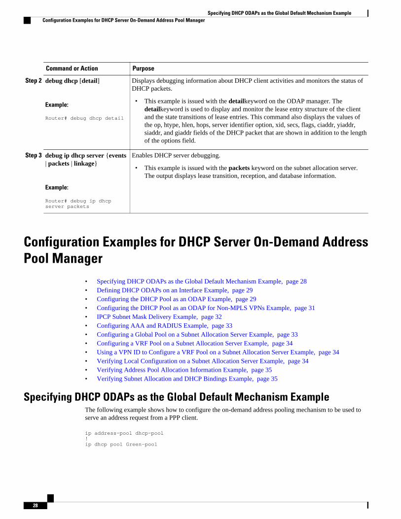
2. debug dhcp [detail]
3. debug ip dhcp server {events | packets | linkage}
DETAILED STEPS
Command or Action Purpose
Step 1 enable
Example:
Router> enable
Enables privileged EXEC mode.
• Enter your password if prompted.
Configuring DHCP ODAP Subnet Allocation Server SupportTroubleshooting the DHCP ODAP Subnet Allocation Server
27
Command or Action Purpose
Step 2 debug dhcp [detail]
Example:
Router# debug dhcp detail
Displays debugging information about DHCP client activities and monitors the status ofDHCP packets.
• This example is issued with the detailkeyword on the ODAP manager. Thedetailkeyword is used to display and monitor the lease entry structure of the clientand the state transitions of lease entries. This command also displays the values ofthe op, htype, hlen, hops, server identifier option, xid, secs, flags, ciaddr, yiaddr,siaddr, and giaddr fields of the DHCP packet that are shown in addition to the lengthof the options field.
Step 3 debug ip dhcp server {events| packets | linkage}
Example:
Router# debug ip dhcp server packets
Enables DHCP server debugging.
• This example is issued with the packets keyword on the subnet allocation server.The output displays lease transition, reception, and database information.
Configuration Examples for DHCP Server On-Demand AddressPool Manager
• Specifying DHCP ODAPs as the Global Default Mechanism Example, page 28• Defining DHCP ODAPs on an Interface Example, page 29• Configuring the DHCP Pool as an ODAP Example, page 29• Configuring the DHCP Pool as an ODAP for Non-MPLS VPNs Example, page 31• IPCP Subnet Mask Delivery Example, page 32• Configuring AAA and RADIUS Example, page 33• Configuring a Global Pool on a Subnet Allocation Server Example, page 33• Configuring a VRF Pool on a Subnet Allocation Server Example, page 34• Using a VPN ID to Configure a VRF Pool on a Subnet Allocation Server Example, page 34• Verifying Local Configuration on a Subnet Allocation Server Example, page 34• Verifying Address Pool Allocation Information Example, page 35• Verifying Subnet Allocation and DHCP Bindings Example, page 35
Specifying DHCP ODAPs as the Global Default Mechanism ExampleThe following example shows how to configure the on-demand address pooling mechanism to be used toserve an address request from a PPP client.
ip address-pool dhcp-pool!ip dhcp pool Green-pool
Specifying DHCP ODAPs as the Global Default Mechanism Example Configuration Examples for DHCP Server On-Demand Address Pool Manager
28
Defining DHCP ODAPs on an Interface ExampleThe following example shows how to configure an interface to retrieve an IP address from an on-demandaddress pool:
interface Virtual-Template 1 ip vrf forwarding green ip unnumbered loopback1 ppp authentication chap peer default ip address dhcp-pool!
Configuring the DHCP Pool as an ODAP ExampleThe following example shows two ODAPs configured to obtain their subnets from an external DHCPserver:
Router# show running-configBuilding configuration...Current configuration : 3943 bytes!version 12.2service timestamps debug uptimeservice timestamps log uptimeno service password-encryption!hostname Router!no logging consoleenable password password!username vpn_green_net1 password 0 labusername vpn_red_net1 password 0 labip subnet-zero!ip dhcp pool green_pool vrf Green utilization mark high 60 utilization mark low 40 origin dhcp subnet size initial /24 autogrow /24!ip dhcp pool red_pool vrf Red origin dhcp!ip vrf Green rd 200:1 route-target export 200:1 route-target import 200:1!ip vrf Red rd 300:1 route-target export 300:1 route-target import 300:1ip cefip address-pool dhcp-pool!no voice hpi capture bufferno voice hpi capture destination !interface Loopback0 ip address 192.0.2.1 255.255.255.255!interface Loopback1 ip vrf forwarding Green ip address 192.0.2.2 255.255.255.255!
Defining DHCP ODAPs on an Interface ExampleConfiguration Examples for DHCP Server On-Demand Address Pool Manager
29
interface Loopback2 ip vrf forwarding Red ip address 192.0.2.3 255.255.255.255!interface ATM2/0 no ip address shutdown no atm ilmi-keepalive!interface ATM3/0 no ip address no atm ilmi-keepalive!interface Ethernet4/0 ip address 192.0.2.4 255.255.255.224 duplex half!interface Ethernet4/1 ip address 192.0.2.5 255.255.255.0 duplex half!interface Ethernet4/2 ip address 192.0.2.6 255.255.255.0 duplex half tag-switching ip!interface Virtual-Template1 ip vrf forwarding Green ip unnumbered Loopback1 ppp authentication chap!interface Virtual-Template2 ip vrf forwarding Green ip unnumbered Loopback1 ppp authentication chap!interface Virtual-Template3 ip vrf forwarding Green ip unnumbered Loopback1 ppp authentication chap!interface Virtual-Template4 ip vrf forwarding Red ip unnumbered Loopback2 ppp authentication chap!interface Virtual-Template5 ip vrf forwarding Red ip unnumbered Loopback2 ppp authentication chap!interface Virtual-Template6 ip vrf forwarding Red ip unnumbered Loopback2 ppp authentication chap!router ospf 100 log-adjacency-changes redistribute connected network 209.165.200.225 255.255.255.224 area 0 network 209.165.200.226 255.255.255.224 area 0 network 209.165.200.227 255.255.255.224 area 0!router bgp 100 no synchronization bgp log-neighbor-changes neighbor 192.0.2.1 remote-as 100 neighbor 192.0.2.2 update-source Loopback0 ! address-family ipv4 vrf Red redistribute connected redistribute static no auto-summary
Configuring the DHCP Pool as an ODAP Example Configuration Examples for DHCP Server On-Demand Address Pool Manager
30
no synchronization network 110.0.0.0 exit-address-family ! address-family ipv4 vrf Green redistribute connected redistribute static no auto-summary no synchronization network 100.0.0.0 exit-address-family ! address-family vpnv4 neighbor 3.3.3.3 activate neighbor 3.3.3.3 send-community extended exit-address-family!ip classlessip route 172.19.0.0 255.255.0.0 10.0.105.1no ip http serverip pim bidir-enable!call rsvp-sync!mgcp profile default!dial-peer cor custom!gatekeeper shutdown!line con 0 exec-timeout 0 0line aux 0line vty 0 4 password password login!end
Configuring the DHCP Pool as an ODAP for Non-MPLS VPNs ExampleThe following example shows how to configure an interface to retrieve an IP address from an on-demandaddress pool. In this example, two non-VRF ODAPs are configured. There are two virtual templates andtwo DHCP address pools, usergroup1 and usergroup2. Each virtual template interface is configured toobtain IP addresses for the peer from the associated address pool.
!ip dhcp pool usergroup1 origin dhcp subnet size initial /24 autogrow /24 lease 0 1!ip dhcp pool usergroup2 origin dhcp subnet size initial /24 autogrow /24 lease 0 1!interface virtual-template1 ip unnumbered loopback1 peer default ip address dhcp-pool usergroup1!interface virtual-template2 ip unnumbered loopback1 peer default ip address dhcp-pool usergroup2
Configuring the DHCP Pool as an ODAP for Non-MPLS VPNs ExampleConfiguration Examples for DHCP Server On-Demand Address Pool Manager
31
IPCP Subnet Mask Delivery ExampleThe following example shows a Cisco 827 router configured to use IPCP subnet masks:
Router# show running-config Building configuration... Current configuration :1479 bytes ! version 12.2 no service single-slot-reload-enable no service pad service timestamps debug datetime msec service timestamps log uptime no service password-encryption ! hostname Router ! no logging buffered logging rate-limit console 10 except errors ! username 6400-nrp2 password 0 lab ip subnet-zero ip dhcp smart-relay ! ip dhcp pool IPPOOLTEST import all origin ipcp ! no ip dhcp-client network-discovery ! interface Ethernet0 ip address pool IPPOOLTEST ip verify unicast reverse-path hold-queue 32 in ! interface ATM0 no ip address atm ilmi-keepalive bundle-enable dsl operating-mode auto hold-queue 224 in ! interface ATM0.1 point-to-point pvc 1/40 no ilmi manage encapsulation aal5mux ppp dialer dialer pool-member 1 ! ! interface Dialer0 ip unnumbered Ethernet0 ip verify unicast reverse-path encapsulation ppp dialer pool 1 dialer-group 1 no cdp enable ppp authentication chap callin ppp chap hostname Router ppp chap password 7 12150415 ppp ipcp accept-address ppp ipcp dns request ppp ipcp wins request ppp ipcp mask request ! ip classless ip route 0.0.0.0 0.0.0.0 Dialer0 no ip http server ! dialer-list 1 protocol ip permit
IPCP Subnet Mask Delivery Example Configuration Examples for DHCP Server On-Demand Address Pool Manager
32
line con 0 exec-timeout 0 0 transport input none stopbits 1 line vty 0 4 login ! scheduler max-task-time 5000 end
Configuring AAA and RADIUS ExampleThe following example shows one pool “Green” configured to obtain its subnets from the AAA (RADIUS)server located at IP address 172.16.1.1:
!aaa new-model!aaa authorization configuration default group radius aaa accounting network default start-stop group radiusaaa session-id common!ip subnet-zero!ip dhcp ping packets 0!ip dhcp pool Green vrf Green utilization mark high 50 utilization mark low 30 origin aaa subnet size initial /28 autogrow /28!ip vrf Green rd 300:1 route-target export 300:1 route-target import 300:1!interface Ethernet1/1 ip address 172.16.1.12 255.255.255.0 duplex half!interface Virtual-Template1 ip vrf forwarding Green no ip address!ip radius source-interface Ethernet1/1!!IP address of the RADIUS server hostradius-server host 172.16.1.1 auth-port 1645 acct-port 1646radius-server retransmit 3radius-server attribute 32 include-in-access-req radius-server attribute 44 include-in-access-reqradius-server key ciscoradius-server vsa send accountingradius-server vsa send authentication
Configuring a Global Pool on a Subnet Allocation Server ExampleThe following example shows how to configure a router to be a subnet allocation server and create a globalsubnet allocation pool named “GLOBAL-POOL” that allocates subnets from the 10.0.0.0/24 network. Theuse of the subnet prefix-length command in this example configures the size of each subnet that isallocated from the subnet pool to support 254 host IP addresses.
ip dhcp pool GLOBAL-POOL network 10.0.0.0 255.255.255.0
Configuring AAA and RADIUS ExampleConfiguration Examples for DHCP Server On-Demand Address Pool Manager
33
subnet prefix-length 24!
Configuring a VRF Pool on a Subnet Allocation Server ExampleThe following example shows how to configure a router to be a subnet allocation server and create a VRFsubnet allocation pool named “VRF-POOL” that allocates subnets from the 172.16.0.0/16 network andconfigures the VPN to match the VRF named “RED.” The use of the subnet prefix-length command inthis example configures the size of each subnet that is allocated from the subnet pool to support 62 host IPaddresses.
ip dhcp pool VRF-POOL vrf RED network 172.16.0.0 /16 subnet prefix-length 26!
Using a VPN ID to Configure a VRF Pool on a Subnet Allocation ServerExample
The following example shows how to configure a router to be a subnet allocation server and create a VRFsubnet allocation pool named “VRF-POOL” that allocates subnets from the 192.168.0.0/24 network andconfigures the VRF named “RED.” The VPN ID must match the unique identifier that is assigned to theclient site. The route target and route distinguisher are configured in the as-number:network-numberformat. The route target and route distinguisher must match. The configuration of the subnet prefix-lengthcommand in this example configures the size of each subnet that is allocated from the subnet pool tosupport 30 host IP addresses.
ip vrf RED rd 100:1 route-target both 100:1 vpn id 1234:123456 exit ip dhcp pool VPN-POOL vrf RED network 192.168.0.0 /24 subnet prefix-length /27 exit
Verifying Local Configuration on a Subnet Allocation Server ExampleThe following example is output from the show running-configcommand. This command can be used toverify the local configuration on a subnet allocation server. The output from this command displays theconfiguration of the subnet prefix-length command under the DHCP pool named “GLOBAL-POOL.” Thetotal size of the subnet allocation pool is set to 254 addresses with the network command. The use of thesubnet prefix-length command configures this pool to allocate a subnet that will support 254 host IPaddresses. Because the total pool size supports only 254 addresses, only one subnet can be allocated fromthis pool.
Router# show running-config | begin dhcpip dhcp pool GLOBAL-POOL network 10.0.0.0 255.255.255.0 subnet prefix-length 24!
Configuring a VRF Pool on a Subnet Allocation Server Example Configuration Examples for DHCP Server On-Demand Address Pool Manager
34
Verifying Address Pool Allocation Information ExampleThe following examples are output from the show ip dhcp poolcommand. This command can be used toverify subnet allocation pool configuration on the subnet allocation server and the ODAP manager. Theoutput from this command displays information about the address pool name, utilization level, configuredsubnet size, total number of addresses (from subnet), pending events, and specific subnet lease information.
The following sample output shows that the configured subnet allocation size is /24 (254 IP addresses), thatthere is a pending subnet allocation request, and that no subnets are in the pool:
Router# show ip dhcp pool ISP-1Pool ISP-1 : Utilization mark (high/low) :100 / 0 Subnet size (first/next) :24 / 24 (autogrow) Total addresses :0 Leased addresses :0 Pending event :subnet request 0 subnet is currently in the pool
The next example shows that the configured subnet allocation size is /24 (254 IP address), the configuredVRF name is “RED” and a subnet containing 254 IP addresses has been allocated but no IP addresses havebeen leased from the subnet:
Router# show ip dhcp pool SUBNET-ALLOCPool SUBNET-ALLOC : Utilization mark (high/low) :100 / 0 Subnet size (first/next) :24 / 24 (autogrow) VRF name :RED Total addresses :254 Leased addresses :0 Pending event :none 1 subnet is currently in the pool : Current index IP address range Leased addresses 10.0.0.1 10.0.0.1 - 10.0.0.254 0
Verifying Subnet Allocation and DHCP Bindings ExampleThe following example is from the show ip dhcp binding command. This command can be used to displaysubnet allocation to DHCP binding mapping information. The output of this command shows the subnetlease to MAC address mapping, the lease expiration, and the lease type (subnet lease bindings areconfigured to be automatically created and released by default). The output that is generated for DHCP IPaddress assignment and subnet allocation is almost identical, except that subnet leases display an IP addressfollowed by the subnet mask (which shows the size of the allocated subnet) in CIDR bit count notation.Bindings for individual IP address display only an IP address and are not followed by a subnet mask.
Router# show ip dhcp bindingBindings from all pools not associated with VRF:IP address Client-ID/ Lease expiration Type Hardware address/ User name10.0.0.0/26 0063.6973.636f.2d64. Mar 29 2003 04:36 AM Automatic 656d.6574.6572.2d47. 4c4f.4241.4c
Additional ReferencesThe following sections provide references related to configuring the DHCP ODAP manager.
Verifying Address Pool Allocation Information ExampleAdditional References
The Cisco Support website provides extensiveonline resources, including documentation and toolsfor troubleshooting and resolving technical issueswith Cisco products and technologies.
To receive security and technical information aboutyour products, you can subscribe to variousservices, such as the Product Alert Tool (accessedfrom Field Notices), the Cisco Technical ServicesNewsletter, and Really Simple Syndication (RSS)Feeds.
Access to most tools on the Cisco Support websiterequires a Cisco.com user ID and password.
http://www.cisco.com/cisco/web/support/index.html
Feature Information for the DHCP Server On-Demand AddressPool Manager
The following table provides release information about the feature or features described in this module.This table lists only the software release that introduced support for a given feature in a given softwarerelease train. Unless noted otherwise, subsequent releases of that software release train also support thatfeature.
Use Cisco Feature Navigator to find information about platform support and Cisco software image support.To access Cisco Feature Navigator, go to www.cisco.com/go/cfn. An account on Cisco.com is not required.
Table 1 Feature Information for the DHCP On-Demand Address Pool Manager
Feature Name Releases Feature Configuration Information
DHCP Server On-DemandAddress Pool Manager for Non-MPLS VPNs
12.2(15)T 12.2(28)SB12.2(33)SRC
This feature was enhanced toprovide ODAP support for non-MPLS VPNs.
The following command wasmodified by this feature: peerdefault ip address.
Verifying Subnet Allocation and DHCP Bindings ExampleFeature Information for the DHCP Server On-Demand Address Pool Manager
Feature Name Releases Feature Configuration Information
DHCP ODAP Server Support 12.2(15)T 12.2(28)SB12.2(33)SRC
This feature introduces thecapability to configure a DHCPserver (or router) as a subnetallocation server. This capabilityallows the Cisco IOS DHCPserver to be configured with apool of subnets for lease toODAP clients.
The following commands wereintroduced or modified by thisfeature: show ip dhcp binding,subnet prefix-length.
DHCP Server On-DemandAddress Pool Manager
12.2(8)T 12.28(SB) 12.2(33)SRC The ODAP manager is used tocentralize the management oflarge pools of addresses andsimplify the configuration oflarge networks. ODAP provides acentral management point for theallocation and assignment of IPaddresses. When a Cisco IOSrouter is configured as an ODAPmanager, pools of IP addressesare dynamically increased orreduced in size depending on theaddress utilization level.
The following commands wereintroduced or modified: aaasession-id, clear ip dhcpbinding, clear ip dhcp conflict,clear ip dhcp subnet, ipaddress-pool, ip address pool,ip dhcp aaa default username,origin, peer default ip address,show ip dhcp pool, utilizationmark high, utilization marklow, vrf.
GlossaryAAA --authentication, authorization, and accounting. Suite of network security services that provide theprimary framework through which access control can be set up on your Cisco router or access server.
Cisco Access Registrar --A RADIUS server that supports service provider deployment of access servicesby centralizing AAA information and simplifying provisioning and management.
client --A host trying to configure its interface (obtain an IP address) using DHCP or BOOTP protocols.
DHCP --Dynamic Host Configuration Protocol.
Verifying Subnet Allocation and DHCP Bindings Example Glossary
38
incremental subnet size --The desired size of the second and subsequent subnets requested for an on-demand pool.
initial subnet size --The desired size of the first subnet requested for an on-demand pool.
IPCP --IP Control Protocol. Protocol that establishes and configures IP over PPP.
MPLS --Multiprotocol Label Switching. Emerging industry standard upon which tag switching is based.
ODAP --on-demand address pool.
PE router --provider edge router.
PPP --Point-to-Point Protocol.
RADIUS -- Remote Authentication Dial-In User Service. Database for authenticating modem and ISDNconnections and for tracking connection time.
relay agent --A router that forwards DHCP and BOOTP messages between a server and a client ondifferent subnets.
releasable subnet --A leased subnet that has no address leased from it.
server --DHCP or BOOTP server.
VHG --Virtual Home Gateway. A Cisco IOS software component that terminates PPP sessions. It is ownedand managed by the service provider on behalf of its customer to provide access to remote users of thatcustomer’s network. A single service provider device (router) can host multiple VHGs of differentcustomers. A VHG can be dynamically brought up and down based on the access pattern of the remoteusers. Note that no single Cisco IOS feature is called the VHG; it is a collection of function and features.
VHG/PE router --A device that terminates PPP sessions and maps the remote users to the correspondingMPLS VPNs.
VPN --Virtual Private Network. Enables IP traffic to use tunneling to travel securely over a public TCP/IPnetwork.
VRF --VPN routing and forwarding instance. A VRF consists of an IP routing table, a derived forwardingtable, a set of interfaces that use the forwarding table, and a set of rules and routing protocols thatdetermine what goes into the forwarding table. In general, a VRF includes the routing information thatdefines a customer VPN site that is attached to a PE router. Each VPN instantiated on the PE router has itsown VRF.
Cisco and the Cisco logo are trademarks or registered trademarks of Cisco and/or its affiliates in the U.S.and other countries. To view a list of Cisco trademarks, go to this URL: www.cisco.com/go/trademarks.Third-party trademarks mentioned are the property of their respective owners. The use of the word partnerdoes not imply a partnership relationship between Cisco and any other company. (1110R)
Any Internet Protocol (IP) addresses and phone numbers used in this document are not intended to beactual addresses and phone numbers. Any examples, command display output, network topology diagrams,and other figures included in the document are shown for illustrative purposes only. Any use of actual IPaddresses or phone numbers in illustrative content is unintentional and coincidental.