CHAPTER Configuring and Monitoring from the Hub Manager 3-1 3 Configuring and Monitoring from the Hub Manager This chapter explains how to use the FastHub 400 series Hub Manager on the FastHub 400M models to change the configuration settings and to monitor the hub or hub stack. This chapter assumes that you have already performed the following tasks described in this guide or in the FastHub 400 10/100 Series Cabling and Start Up: • “Connecting to the Console Port (FastHub 400M Models)” section on page 2-14 • “Assigning IP Information to the Hub (FastHub 400M Models)” section on page 2-16 • “Accessing the FastHub 400 Series Hub Manager” section on page 2-21 Note Procedures for changing the configuration settings and detailed descriptions of the fields are also provided in the hub manager online help.
Transcript
C H A P T E R
Configuring and Monitoring from the Hub Manage
3
Configuring and Monitoring from the Hub Manager
This chapter explains how to use the FastHub 400 series Hub Manager on the FastHub 400M models to change the configuration settings and to monitor the hub or hub stack. This chapter assumes that you have already performed the following tasks described in this guide or in the FastHub 400 10/100 Series Cabling and Start Up:
• “Connecting to the Console Port (FastHub 400M Models)” section on page 2-14
• “Assigning IP Information to the Hub (FastHub 400M Models)” section on page 2-16
• “Accessing the FastHub 400 Series Hub Manager” section on page 2-21
Note Procedures for changing the configuration settings and detailed descriptions of the fields are also provided in the hub manager online help.
r 3-1
Navigating in the Hub Manager
Navigating in the Hub ManagerAt the top of each hub manager page is a menu bar. Figure 3-1 describes the functions of the pages accessible from the menu bar.
Note On Netscape Communicator only, when the cursor is above a topic on the menu bar, a pop-up briefly describes the options on that particular page.
List neighboring devices;define Cisco Discovery Protocol parameters
Define system-wide hub parameters
Define port parameters; display Switched Uplink Module Management page
Define group parameters
1452
4
Define SNMP community strings; trap manager parameters
Define console port; upgrade firmware options
FastHub 400 10/100 Series Installation and Configuration Guide3-2
Saving Your Changes
Saving Your ChangesYou can change the hub settings by entering information into fields, adding and removing list items, or selecting and deselecting check boxes. Click Apply to save your changes. Click Revert to discard all your unsaved changes and return the previous settings to the page.
Note After you click Apply, you cannot revert to the previous settings.
• When you enter information in fields and select or deselect check boxes, the changes are saved and immediately take effect after you click Apply.
• When you add items to or remove them from lists, the changes take effect immediately. It is not necessary to click Apply.
Note Wait approximately 30 seconds before turning off the hub to be sure the changes are saved.
Configuring and Monitoring from the Hub Manager 3-3
Assigning or Changing Basic Hub Information
Assigning or Changing Basic Hub InformationYou can assign or change basic descriptions about the hub from the hub manager Home Page (Figure 3-2). You can also assign a password to the hub management interfaces (hub manager and CLI-privileged commands) and monitor network activity through the live hub image. This page also provides a hotlink that opens a Telnet session to the hub command-line interface (CLI), in addition to hotlinks for contacting Cisco Systems resources.
Click HOME on the menu bar to display the Home Page (Figure 3-2) and check and change hub information.
Note This section provides detailed information about this page and procedures on changing the settings. When you are using the hub manager, click Help from the Home Page to access this information online.
FastHub 400 10/100 Series Installation and Configuration Guide3-4
Assigning or Changing the Hub Name and Description
Figure 3-2 Home Page
Assigning or Changing the Hub Name and DescriptionYou can assign or change the following information about the hub (be sure to click Apply to save changes):
• Name (maximum of 255 characters)
• Physical location (maximum of 255 characters)
• Name of the person responsible for managing the hub (maximum of 255 characters)
Initially assigned after the hubis installed. Can be changedfrom the IP Management page.
1536
4
HOME PORT GROUP IP SNMP CDP SYSTEM
Configuring and Monitoring from the Hub Manager 3-5
Assigning or Changing Basic Hub Information
Assigning or Changing the Hub PasswordBy default, no password is assigned to the hub management interfaces. You can restrict access to the hub manager or CLI-privileged commands by assigning a password. If a user fails to enter the password within a set number of attempts, the hub sends an SNMP trap to the SNMP trap manager to alert you, via in-band management messages, of the failed attempts. (For information about trap managers, see the “Changing the SNMP Settings” section on page 3-34.)
When a password is assigned, the password prompt is displayed when you or any other user opens a hub manager session and displays the Home Page. The Home Page is redisplayed only after you enter the correct password. If the password prompt reappears, reenter the correct password.
To assign or change the password to the hub manager or CLI-privileged commands:
Step 1 Enter a character string (4 to 8 characters, case sensitive) in the Assign/Change Password field.
Step 2 Enter the same character string in the Reconfirm Password field.
Step 3 Click Apply.
The connection with the hub is broken. The browser prompts you for the new password.
Step 4 Enter the new password at the password authentication prompt, and click OK.
If you have forgotten or do not know the password, see the “Recovering from a Lost or Forgotten Password” section on page 4-13.
FastHub 400 10/100 Series Installation and Configuration Guide3-6
Using the Hub Image to Monitor the Hub
Using the Hub Image to Monitor the HubThe Home Page displays the front-panel image of the hub (Figure 3-3). The following sections provide information on how to use the hub image.
Figure 3-3 Hub Image
Note The hub image on the Home Page does not display both the last fixed 10/100 network port and the uplink port (which are ports 12x and 12 on the FastHub 412 models or ports 24x and 24 on the FastHub 424 models). The last fixed port on the hub image represents both ports 12x and 12 or ports 24x and 24, depending on the model.
In Figure 3-3, the hub image shows that a 10BaseT/100BaseTX switched uplink module is installed in the hub.
1802
6
Click the Modebutton to changethe mode thatthe LEDs displayfor the fixed10/100 ports.
HOME PORT GROUP IP SNMP CDP SYSTEM
Click a port to display itssettings, status, and statistics.
Click to display the settings, status, and statistics of an installed 10BaseT/100BaseTX or 100BaseFX switched uplink module.
Shows when another hub is connected to a stacking connector on the hub rear panel.
Configuring and Monitoring from the Hub Manager 3-7
Assigning or Changing Basic Hub Information
SYSTEM and RPS LEDs on the Hub ImageThe hub image on the Home Page shows the front-panel LED colors at the last poll interval and refreshes every 30 seconds. The LEDs show system and RPS status, port status, and port speed.
Note The hub image does not show the 10 and 100 activity/collision LEDs. To find out if any of the hub ports are operating at 10 or 100 Mbps, check the actual 10 and 100 LEDs on the hub, or click the specific port on the image to display the settings on the Port Management Page.
The SYSTEM LED on the hub image always displays green, showing that the hub is operating normally. It does not turn amber if a nonfatal POST failure exists. To verify that there are no nonfatal POST failures, check the actual SYSTEM LED on the hub or use the Diagnostic Console - Systems Engineering Menu (see the “Using the Diagnostic Console - Systems Engineering Menu” section on page 4-8).
The colors of the RPS LED on the hub image show the RPS status (Table 3-1).
Table 3-1 Descriptions of the RPS LED on the Hub Image
LED Color Description
Blue (off) Internal power supply is powered up. RPS is not powered up.
Solid green RPS is powered up and operational. Internal power supply is not powered up.
Flashing green Internal power supply and RPS are both powered up and the internal power supply is powering the hub. If the internal power supply fails, the hub powers down and, after 15 seconds, restarts by using the power from the RPS. The hub goes through its normal boot sequence when it restarts.
Solid amber RPS is connected but not functioning properly. One of the power supplies in the RPS could be powered down or a fan on the RPS could have failed.
FastHub 400 10/100 Series Installation and Configuration Guide3-8
Using the Hub Image to Monitor the Hub
Mode Button and 10/100 Port LEDs on the Hub ImageClick the Mode button on the hub image to change the mode of the port LEDs (Table 3-2). The default mode for the port LEDs is port status. The colors of the port LEDs on the hub image display the status or speed of the individual port (Table 3-3). When you select the port speed mode, the hub remains in that mode for approximately 30 seconds before returning to the default mode, port status.
Note The hub image does not show the port LEDs in bandwidth-utilization mode (UTL).
Note The hub image on the Home Page does not display both the last 10/100 network port and the uplink port (ports 12x and 12 on the FastHub 412 models or ports 24x and 24 on the FastHub 424 models). The LED above port 12 or 24 on the hub image represents both ports 12x and 12 or ports 24x and 24.
Table 3-2 Changing Between Modes on the Hub Image
For this Mode... Push the Mode Button Until...
Port status The STAT LED is green.
100BaseT connections The SPD LED is green.
Table 3-3 Descriptions of the Port LED on the Hub Image
LED Color Description
Port Status
Blue (off) No link.
Solid green Link operational.
Solid amber The port is partitioned. After a packet is successfully sent over this port, the LED is green (normal operating state).
Port Speed
Blue (off) Port is connected to a 10BaseTX network device.
Green Port is connected to a 100BaseTX network device.
Configuring and Monitoring from the Hub Manager 3-9
Assigning or Changing Basic Hub Information
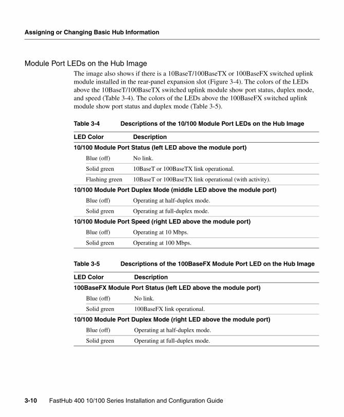
Module Port LEDs on the Hub ImageThe image also shows if there is a 10BaseT/100BaseTX or 100BaseFX switched uplink module installed in the rear-panel expansion slot (Figure 3-4). The colors of the LEDs above the 10BaseT/100BaseTX switched uplink module show port status, duplex mode, and speed (Table 3-4). The colors of the LEDs above the 100BaseFX switched uplink module show port status and duplex mode (Table 3-5).
Table 3-4 Descriptions of the 10/100 Module Port LEDs on the Hub Image
LED Color Description
10/100 Module Port Status (left LED above the module port)
Blue (off) No link.
Solid green 10BaseT or 100BaseTX link operational.
Flashing green 10BaseT or 100BaseTX link operational (with activity).
10/100 Module Port Duplex Mode (middle LED above the module port)
Blue (off) Operating at half-duplex mode.
Solid green Operating at full-duplex mode.
10/100 Module Port Speed (right LED above the module port)
Blue (off) Operating at 10 Mbps.
Solid green Operating at 100 Mbps.
Table 3-5 Descriptions of the 100BaseFX Module Port LED on the Hub Image
LED Color Description
100BaseFX Module Port Status (left LED above the module port)
Blue (off) No link.
Solid green 100BaseFX link operational.
10/100 Module Port Duplex Mode (right LED above the module port)
Blue (off) Operating at half-duplex mode.
Solid green Operating at full-duplex mode.
FastHub 400 10/100 Series Installation and Configuration Guide3-10
Using the Hub Image to Monitor the Hub
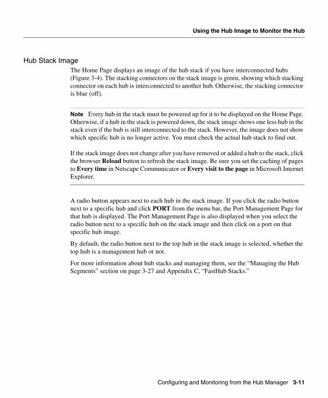
Hub Stack ImageThe Home Page displays an image of the hub stack if you have interconnected hubs (Figure 3-4). The stacking connectors on the stack image is green, showing which stacking connector on each hub is interconnected to another hub. Otherwise, the stacking connector is blue (off).
Note Every hub in the stack must be powered up for it to be displayed on the Home Page. Otherwise, if a hub in the stack is powered down, the stack image shows one less hub in the stack even if the hub is still interconnected to the stack. However, the image does not show which specific hub is no longer active. You must check the actual hub stack to find out.
If the stack image does not change after you have removed or added a hub to the stack, click the browser Reload button to refresh the stack image. Be sure you set the caching of pages to Every time in Netscape Communicator or Every visit to the page in Microsoft Internet Explorer.
A radio button appears next to each hub in the stack image. If you click the radio button next to a specific hub and click PORT from the menu bar, the Port Management Page for that hub is displayed. The Port Management Page is also displayed when you select the radio button next to a specific hub on the stack image and then click on a port on that specific hub image.
By default, the radio button next to the top hub in the stack image is selected, whether the top hub is a management hub or not.
For more information about hub stacks and managing them, see the “Managing the Hub Segments” section on page 3-27 and Appendix C, “FastHub Stacks.”
Configuring and Monitoring from the Hub Manager 3-11
Assigning or Changing Basic Hub Information
Figure 3-4 Hub Stack Image
Note In Figure 3-4, the top hub on the stack image is a management hub, as indicated by the label “Master,” and is the primary management hub. The third hub in the stack is the secondary management hub. The second and fourth hubs are not management hubs.
A 10BaseT/100BaseTX switched uplink module is installed in the second hub, and a 100BaseFX switched uplink module is installed in the fourth.
Shows when another hub is connected to a stacking connector on the hub rear panel.
1775
7
Click the Modebutton to changethe mode thatthe LEDs displayfor the fixed10/100 ports.
HOME PORT GROUP IP SNMP CDP SYSTEM
Click a port to display itssettings, status, and statistics.
Click to display the settings, status, and statistics of an installed 10BaseT/100BaseTX or 100BaseFX switched uplink module.
FastHub 400 10/100 Series Installation and Configuration Guide3-12
Using Telnet to Open a CLI Session
Using Telnet to Open a CLI SessionClick Telnet to open a session on the hub command-line interface (CLI).
Connecting to Cisco Systems’ ResourcesThe Home Page provides these hotlinks to connect to Cisco Systems’ resources:
• Click Cisco Connection Online (CCO) to display the CCO home page (www.cisco.com), which contains links to the support sites for downloading the latest software and displaying the latest Cisco documentation.
• Click Technical Assistance Center (TAC) to open a new message composition window to send e-mail to TAC ([email protected]). You can also phone TAC at 800-553-2447 or 408-526-7209.
• Click HTML Interface Development Group to open a new message composition window to send e-mail to the hub manager development group ([email protected]).
Configuring and Monitoring from the Hub Manager 3-13
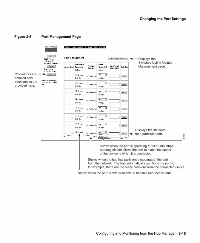
Changing the Port Settings
Changing the Port SettingsBy default, each 10/100 network port and the 10/100 uplink port on the hub are enabled to transmit packets to and receive them from the device to which it is connected, automatically matching its speed.
Click PORT on the menu bar or click the port on the hub image on the Home Page to display the Port Management Page (Figure 3-5), check the status of the port, and change the port settings.
If you have a hub stack, click the radio button next to the specific hub image on the Home Page, and either click PORT from the menu bar or click the port on the specific hub image. The Port Management Page displays the port settings for the specific hub.
Note This section provides detailed information about this page and procedures on changing the settings. When you are using the hub manager, click Help from the Port Management Page to access this information online.
FastHub 400 10/100 Series Installation and Configuration Guide3-14
Shows when the port is able or unable to transmit and receive data.
Shows when the hub has partitioned (separated) the portfrom the network. The hub automatically partitions the port if,for example, there are too many collisions from the connected device.
Shows when the port is operating at 10 or 100 Mbps.Autonegotiation allows the port to match the speedof the device to which it is connected.
HOME PORT GROUP IP SNMP CDP SYSTEM
Configuring and Monitoring from the Hub Manager 3-15
Changing the Port Settings
Enabling or Disabling a PortBy default, all ports are enabled. To disable a port:
Step 1 In the Link Status: Requested/Actual column, deselect the Enable check box.
Step 2 Click Apply.
A linkDown trap is sent to the management station if you configured an SNMP manager.
To reenable a port:
Step 1 In the Link Status: Requested/Actual column, select the Enable check box.
Step 2 Click Apply.
A linkUp trap is sent to the management station if you configured an SNMP manager.
Checking the Link and Partition StatusThe Link Status: Requested/Actual column displays the actual status of the port. Each port is always in one of these link states:
The Partition Status column displays whether or not the port has been partitioned by the hub, which usually happens as a result of excessive collisions or a network loop. Each port is always in one of these partition states:
Link Up Port can transmit and receive data.
Link Down Port is unable to transmit or receive data.
Partitioned Port is isolated from the network communications.
Not Partitioned Port is not isolated from the network communications.
FastHub 400 10/100 Series Installation and Configuration Guide3-16
Changing the Port Transmission Speed
Changing the Port Transmission SpeedBy default, the ports automatically match the transmission speed of the attached device. To change the port speed:
Step 1 From the Speed: Requested/Actual drop-down list, select 10 Mbps, 100 Mbps, or Auto (autonegotiate). The default is Auto.
Step 2 Click Apply.
Note If the other device does not autonegotiate, the hub port automatically negotiates to 10 Mbps.
Assigning or Changing a Port Name or DescriptionTo assign a name or description to a port:
Step 1 In the Port Name/Description column, enter the port name or a description (up to 20 characters) of how the port is connected.
Step 2 Click Apply.
Displaying the Switched Uplink Module Management PageClick Switched Uplink Module to display this page.
Configuring and Monitoring from the Hub Manager 3-17
Changing the Port Settings
Checking or Resetting Port StatisticsFrom the Port Management Page, select a port, and click View to see the statistics for a particular port on the hub. The Detailed Port Statistics Page (Figure 3-6) for the selected port displays the port statistics. Table 3-6 lists the statistics displayed on the page.
Click Reset Port Statistics to reset the statistics.
The hub manager does not automatically refresh the statistics shown on this page. Click Reload to refresh the statistics shown on this page.
FastHub 400 10/100 Series Installation and Configuration Guide3-18
Checking or Resetting Port Statistics
Table 3-6 Error Descriptions on the Detailed Port Statistics Page
Packets Total number of packets received by the port.
Bytes Total number of bytes received by the port.
FCS Errors Number of frame check sequence (FCS) errors indicating that frames of data are being corrupted during transmission.
Alignment Errors Number of alignment errors (caused if all bytes are not received whole) received by the port.
Packets Too Long Number of packets received by the port that exceed the maximum size for IEEE 802.3 frames.
Short Events Number of packets received by the port that are smaller than runts, which are smaller than the minimum size for IEEE 802.3 packets.
Packets Too Short Number of frames received by the hub that are smaller than the minimum size for IEEE 802.3 frames.
Collisions Number of times the hub and the connected device attempt to transmit at the same time.
Late Events Number of frames that experienced a collision late in transmission.
Very Long Events Number of packets that exceed the maximum length prescribed in IEEE 802.3.
Data Rate Mismatches Number of frames whose timing no longer matches the transmit frequency between the hub and the connected device.
Autopartitions Number of times the port automatically partitions the segments attached to it.
Total Errors Total number of errors received by the port.
Configuring and Monitoring from the Hub Manager 3-19
Changing the Module Port Settings
Changing the Module Port SettingsIf you have an optional switched uplink module installed in the rear-panel expansion slot on the hub, you can manage the module port as you would the 10/100 network and uplink ports.
Click PORT on the menu bar, and click Switched Uplink Module from the Port Management Page to display the Switched Uplink Module Management Page (Figure 3-7) and check and change the settings. You can also click the module port on the hub image on the Home Page to display the Switched Uplink Module Management Page.
Note This section provides detailed information about this page and procedures on changing the settings. When you are using the hub manager, click Help on the Switched Uplink Module Management Page to access this information online.
For more information about the switched uplink modules, see Appendix D, “Switched Uplink Modules.”
FastHub 400 10/100 Series Installation and Configuration Guide3-20
Changing the Module Port Settings
Figure 3-7 Switched Uplink Module Management Page
Note Figure 3-7 shows the Switched Uplink Module Management Page. This example shows that hubs 1, 3, and 4 have modules installed. Hub 2 is powered down but still interconnected to the stack.
Shows if the hub has a10BaseT/100BaseTX or 100BaseFX
switched uplink module installed.
Shows when the port isable or unable to transmit
and receive data.
Shows when the module port is operating at 10 or 100 Mbps.Autonegotiation allows the 10BaseT/100BaseTX module portto match the speed of the device to which it is connected.Speed negotiation is not applicable to the 100BaseFX module port.
Shows when the module port is operating at half-or full-duplex mode. Autonegotiation allows themodule port to match the duplex mode of thedevice to which it is connected.
HOME PORT GROUP IP SNMP CDP SYSTEM
Shows on which hub in the stack the module is installed.
Configuring and Monitoring from the Hub Manager 3-21
Changing the Module Port Settings
Enabling or Disabling the Module PortBy default, the module port is enabled. To disable the module port:
Step 1 In the Status: Requested/Actual column, deselect the Enable check box.
Step 2 Click Apply.
A linkDown trap is sent to the management station if you configured an SNMP manager.
To reenable the module port:
Step 1 In the Status: Requested/Actual column, select the Enable check box.
Step 2 Click Apply.
A linkUp trap is sent to the management station if you configured an SNMP manager.
Checking the Module Port StatusThe Status: Requested/Actual column displays the actual status of the module port. The module port is always in one of these link states:
Checking the Type of Module InstalledThe Medium column displays the type of switched uplink module installed in the hub:
Link Up Port can transmit and receive data.
Link Down Port is unable to transmit or receive data.
10BaseT/100BaseTX 10BaseT/100BaseTX switched uplink module is installed.
100BaseFX-SC 100BaseFX switched uplink module is installed.
FastHub 400 10/100 Series Installation and Configuration Guide3-22
Changing the Module Port Transmission Speed
Changing the Module Port Transmission SpeedBy default, the 10BaseT/100BaseTX module port automatically matches the transmission speed of the attached device. To change the module port transmission speed:
Step 1 From the Speed: Requested/Actual drop-down list, select 10 Mbps, 100 Mbps, or Auto (autonegotiate).
The default is Auto. The 10-Mbps and Auto options are available only to the 10BaseT/100BaseTX module port.
Step 2 Click Apply.
Note If the other device does not autonegotiate, the hub port automatically negotiates to 10 Mbps. Speed negotiation does not apply to the 100BaseFX switched uplink module.
Changing the Module Port Duplex ModeFull-duplex operation is simultaneous transmission of data in both directions across a link. For example, a 100BaseTX switched port operating in full-duplex mode can provide up to 200 Mbps of bandwidth across the switched link.
When autonegotiation is selected on the module port, it automatically configures for full-duplex operation if the connected device also supports full duplex. If the attached device does not support full-duplex operation, the module port automatically configures to half-duplex operation.
To change the module port duplex mode:
Step 1 From the Duplex Mode: Requested/Actual drop-down list, select Half, Full, or Auto (autonegotiate).
The default for the 10BaseT/100BaseTX module port is Auto. The default for the 100BaseFX module port is Half.
Step 2 Click Apply.
Note If the other device does not autonegotiate, the hub port automatically negotiates to half duplex.
Configuring and Monitoring from the Hub Manager 3-23
Changing the Module Port Settings
Assigning or Changing a Module Port Name or DescriptionTo assign a name or description to a module port:
Step 1 In the Port Name/Description column, enter the port name or a description (up to 20 characters) of how the module port is connected.
Step 2 Click Apply.
Checking or Resetting Module StatisticsFrom the Switched Uplink Module Management Page, select the hub on which the module is installed, and click View to see the statistics of the module. The Detailed Switched Uplink Module Statistics Page (Figure 3-8) displays the module statistics. Table 3-7 lists the statistics displayed on the page.
Click Reset Switched Uplink Module Statistics to reset the statistics.
The hub manager does not automatically refresh the statistics shown on this page. Click Reload to refresh the statistics shown on this page.
FastHub 400 10/100 Series Installation and Configuration Guide3-24
Resets the statistics forthe switched uplink module.
Refreshes the statisticsdisplayed on this page.
1760
9
Configuring and Monitoring from the Hub Manager 3-25
Changing the Module Port Settings
Table 3-7 Error Descriptions on the Detailed Switched Uplink Module Statistics Page
Total Bytes Received Total number of bytes received by the port.
Total Packets Received Total number of packets received by the port.
Broadcast Packets Received Total number of broadcast packets received by the port.
Multicast Packets Received Total number of multicast packets received by the port.
CRC/Alignment Errors Number of frames received by the port that are not an integral number of octets in length and do not pass the frame check sequence (FCS) test.
Undersize Packets Number of packets less than 64 bytes received by the port.
Oversize Packets Number of packets longer than 1518 bytes received by the port.
Fragments Number of SMT packets received by the port.
Very Long Events Number of packets that exceed the maximum length prescribed in IEEE 802.3.
Collisions Number of times the port and the connected device attempt to transmit at the same time.
Number of packets received in these lengths in bytes.
FastHub 400 10/100 Series Installation and Configuration Guide3-26
Managing the Hub Segments
Managing the Hub SegmentsYou can interconnect up to four FastHub 400 models (a maximum of 96 ports) and manage that hub stack as a single logical repeater. To provide management to the stack, the stack must include at least one FastHub 412M or FastHub 424M hub. You can have a second management hub in the stack to act as a redundant stack manager in case the primary manager fails. For complete information and guidelines on stacking hubs, see Appendix C, “FastHub Stacks.”
By default, each hub in the stack is connected to the network. Click GROUP on the menu bar to display the Group Management Page (Figure 3-9), isolate a hub from the network, and display the statistics of each hub in the stack.
Note This section provides detailed information about this page and procedures on changing the settings. When you are using the hub manager, click Help from the Group Management Page to access this information online.
Figure 3-9 Group Management Page
Note Figure 3-9 shows the Group Management Page when there are at least two hubs in the stack.
Identifies the hubs in the stack.The hub physically located atthe top of the stack is Group 1.
HOME PORT GROUP IP SNMP CDP SYSTEM
• Isolates a particular hubfrom the network.
• Connects a particular hubto the network.
Configuring and Monitoring from the Hub Manager 3-27
Managing the Hub Segments
This page displays the number of active hubs (groups) in the hub stack. Group 1 always represents the hub at the top of the stack, and the hub below Group 1 is Group 2, and so on. If you remove a hub from the stack, this page automatically renumbers the hubs accordingly.
Note Every hub in the stack must be powered up for it to be displayed on the Home Page and on the Group Management Page. Otherwise, if a hub in the stack is powered down, the stack image shows one less hub in the stack even if the hub is still interconnected to the stack. However, the image does not show which specific hub is no longer active. You must check the actual hub stack to find out.
If the stack image does not change after you have removed or added a hub to the stack, click the browser Reload button to refresh the stack image. Be sure you set the caching of pages to Every time in Netscape Communicator or Every visit to the page in Microsoft Internet Explorer.
If a hub stack has more than one management hub, the upper management hub in the stack is the primary management hub. The lower management hub is the secondary management hub.
To manage the hub stack, you can use the system information (such as the IP, CDP, and SNMP information) assigned to the primary management hub. The primary management hub also stores the port settings of each hub in the stack. If the primary management hub becomes inactive or is disconnected from the stack, the secondary management hub becomes the primary management hub and uses the same stack information.
• If a stack has only one management hub and another management hub is added to the stack, the system information from the management hub that has the longest system-up time is used by the topmost management hub. This happens if the new management hub is added either above or below the preexisting management hub.
• If you replace the only management hub in the stack with a different management hub, the stack will use the settings of the newly installed management hub.
Note If you have a stack that has two management hubs and you remove one management hub from the stack, it will have the same IP address as the stack. Avoid IP conflict by changing the IP address of the removed management hub before you reuse it and connect it to another hub stack in the network.
FastHub 400 10/100 Series Installation and Configuration Guide3-28
Connecting or Isolating a Hub Segment
Connecting or Isolating a Hub SegmentBy default, each hub in the stack is connected to the network. To isolate a hub from the network:
Step 1 Select Isolated from the Isolation Status drop-down list.
You can use the Isolated option if you need to troubleshoot a specific hub in the stack and do not want to affect the devices to which that particular hub is connected.
When you isolate a hub, keep the following considerations in mind:
• If you isolate a hub in the stack, the hubs above and below the isolated hub will still communicate with each other as long as the isolated hub is interconnected to the stack.
• If you isolate a hub in the stack other than the primary management hub, and your management station is not connected to the isolated hub, the Home Page will display the stack image, including the isolated hub. You can still manage the stack, including the isolated hub, from the hub manager.
• If your hub stack has only one management hub and you isolate that management hub, the Home Page will display only the image of the management hub (not the stack image). You will not be able to manage the stack from the hub manager.
Note If you do not isolate a hub and if you keep it interconnected to the stack but only power down that hub, the hubs above and below that powered-down hub will still communicate with each other. However, you will not be able to manage that hub, and it will not be displayed from the hub manager.
Step 2 Click Apply.
To reconnect an isolated hub to the network:
Step 1 Select Connected from the Isolation Status drop-down list.
Step 2 Click Apply.
Configuring and Monitoring from the Hub Manager 3-29
Managing the Hub Segments
Checking or Resetting Hub StatisticsFrom the Group Management Page, select the hub, and click View to see the statistics of a single hub or a hub in the hub stack. The Detailed Group Statistics Page (Figure 3-10) for the hub (group) you selected displays the hub statistics. Table 3-8 lists the statistics displayed on the page.
Click Reset Group Statistics to reset the statistics.
The hub manager does not automatically refresh the statistics shown on this page. Click Reload to refresh the statistics shown on this page.
FastHub 400 10/100 Series Installation and Configuration Guide3-30
Checking or Resetting Hub Statistics
Table 3-8 Error Descriptions on the Detailed Group Statistics Page
Packets Total number of packets received by the port.
Bytes Total number of bytes received by the port.
FCS Errors Number of frame check sequence (FCS) errors indicating that frames of data are being corrupted during transmission.
Alignment Errors Number of alignment errors (caused if all bytes are not received whole) received by the port.
Packets Too Long Number of packets received by the port that exceed the maximum size for IEEE 802.3 frames.
Short Events Number of packets received by the port that are smaller than runts, which are smaller than the minimum size for IEEE 802.3 packets.
Packets Too Short Number of frames received by the hub that are smaller than the minimum size for IEEE 802.3 frames.
Collisions Number of times the hub and the connected device attempt to transmit at the same time.
Late Events Number of frames that experienced a collision late in transmission.
Very Long Events Number of packets that exceed the maximum length prescribed in IEEE 802.3.
Data Rate Mismatches Number of frames whose timing no longer matches the transmit frequency between the hub and the connected device.
Autopartitions Number of times the port automatically partitions the segments attached to it.
Total Errors Total number of errors received by the port.
Configuring and Monitoring from the Hub Manager 3-31
Changing the Hub IP Information
Changing the Hub IP InformationIP information identifies the hub (or managed hub stack) to the network and is necessary to manage the hub (or hub stack) through the hub manager, the CLI, or SNMP. This information is usually assigned to the management hub after it is installed and initially started up. (See the “Assigning IP Information to the Hub (FastHub 400M Models)” section on page 2-16.)
The IP Address field displays the current IP address of the hub. Click IP on the menu bar to display the IP Management Page (Figure 3-11) and change hub IP information.
Note If you have a stack that has two management hubs and you remove one management hub from the stack, it will have the same IP address as the stack. Avoid IP conflict by changing the IP address of the removed management hub before you reuse it and connect it to another hub stack in the network. For complete information and guidelines on managing hub stacks, see the “Managing the Hub Segments” section on page 3-27 and the “Managing a Hub Stack” section on page C-6.
Note This section provides detailed information about this page and procedures on changing the settings. When you are using the hub manager, click Help on the IP Management Page to access this information online.
• User-Configured allows you to manually changethe hub IP information. The IP address andsubnet mask must be in the same subnet.
• BootP Get IP enables the hub to automaticallyassign hub IP information if it is connected toa network with a BootP server. When enabled,this option does not allow hub IP information tobe manually changed.
HOME PORT GROUP IP SNMP CDP SYSTEM
FastHub 400 10/100 Series Installation and Configuration Guide3-32
Changing the Hub IP Information
Caution Changing the hub IP address on this page will end your hub manager session. To open a new session, enter the new IP address in the URL field if you are using Communicator (the Address field if you are using Internet Explorer).
To manually change the hub IP information:
Step 1 Select User-Configured from the IP State drop-down list.
Note You can manually change the hub IP information only if the User-Configured option is enabled.
Note Use the BootP Get IP option if you want the BootP (Boot Protocol) server to assign the IP information. The hub must be connected to a network that has a BootP server. The BootP Get IP option becomes active when you restart the hub. If this option is enabled, you cannot manually change IP information.
The default is User-Configured.
Step 2 Enter a new IP address for the hub in the IP Address field.
Caution If you enter a new address and click Apply, the hub manager loses contact with the hub. Enter the new IP address of the hub in the Location field if you are using Communicator (the Address field if you are using Internet Explorer) to redisplay the hub manager.
Step 3 Enter the subnet mask for the hub.
The subnet mask must be in the same subnet as the IP address.
Step 4 Enter the IP address of the default gateway.
The default gateway is the router that the hub uses to reach IP subnets other than the local subnet to which the hub is attached.
Step 5 Click Apply.
Configuring and Monitoring from the Hub Manager 3-33
Changing the SNMP Settings
Changing the SNMP SettingsSNMP provides the means to manage and monitor the hub (or managed hub stack) through the Management Information Base (MIB) objects. Additional information about SNMP and MIB objects is provided in the “Overview of SNMP” section on page 1-17 and the “Accessing the MIB Files through SNMP” section on page 2-23.
Click SNMP on the menu bar to display the SNMP Management Page (Figure 3-12) and check and change the SNMP settings.
Note This section provides detailed information about this page and procedures on changing the settings. When you are using the hub manager, click Help on the SNMP Management Page to access this information online.
Passwords that allow read-only(Get requests) and read-write(Set requests) access to thehub MIB-object information.
Up to four managementstations can receive traps(alerts of certain events)generated by the hub.Use the traps to monitorthe hub.
Up to four management stations can issuewrite requests to change the hub configurationsettings through the MIB variables.
HOME PORT GROUP IP SNMP CDP SYSTEM
FastHub 400 10/100 Series Installation and Configuration Guide3-34
Changing the SNMP Read and Write Community Strings
Changing the SNMP Read and Write Community StringsCommunity strings serve as passwords for SNMP messages. You can assign community strings that enable the hub to validate SNMP read and read-write requests from a management station.
To change the SNMP Read community string:
Step 1 Enter up to 32 characters in the Read Community String field. The default is public.
Step 2 Click Apply.
To change the SNMP Write community string:
Step 1 Enter up to 32 characters in the Write Community String field. The default is private.
Step 2 Click Apply.
Assigning or Changing Trap ManagersA trap manager is an SNMP management station that receives traps, which are the system alerts generated by the hub. If no trap manager is defined, no traps are issued. Up to four trap managers and their accompanying community strings can be entered.
To assign a trap manager:
Step 1 Enter the IP address and a community string (up to 32 characters) in the IP Address and Trap Manager Community String fields.
Step 2 Click Add.
To remove a trap manager:
Step 1 Select the manager from the Current list.
Step 2 Click Remove.
Configuring and Monitoring from the Hub Manager 3-35
Changing the SNMP Settings
Enabling or Disabling Trap GenerationBy default, the Enable Authentication Trap Generation check box is selected (meaning this parameter is enabled). When this check box is selected, the hub generates authentication traps that alert a management station to SNMP requests that are not accompanied by a valid community string. However, even if this parameter is enabled, no trap can be generated if no trap manager addresses are specified. (For information about trap manager settings, see the “Assigning or Changing Trap Managers” section on page 3-35). If you change this check box, click Apply to save your changes.
By default, the Enable Link Up/Link Down Trap Generation check box is selected (meaning this parameter is enabled). If you change this check box, click Apply to save your changes.
The hub generates linkDown traps when a port is suspended or disabled for these reasons:
• User disables the port.
• Link is down.
The hub generates linkUp traps when a port is enabled for these reasons:
• Presence of linkbeat.
• Management intervention enables the port.
Assigning or Changing Write ManagersA write manager is an SNMP management station that can issue write requests to the hub. Up to four IP addresses of stations can be defined.
To assign a write manager:
Step 1 Enter the management station IP address in the IP Address field.
Step 2 Click Add.
To remove a write manager:
Step 1 Select the manager from the Current list.
Step 2 Click Remove.
FastHub 400 10/100 Series Installation and Configuration Guide3-36
Changing the CDP Settings
Changing the CDP SettingsThe Cisco Discovery Protocol (CDP) enables the hub (or managed hub stack) to advertise its existence to other Cisco devices in the network. When CDP is enabled, the hub manager and network management applications have an accurate picture of the network at any time because CDP gathers information about device types, links between devices, and the number of interfaces within each device.
By default, the hub is CDP-enabled. Click CDP on the menu bar to display the CDP Management Page (Figure 3-13) and check and change the CDP settings.
Note This section provides detailed information about this page and procedures on changing the settings. When you are using the hub manager, click Help on the CDP Management Page to access this information online.
Opens the web console ofa connected neighboring device.
Opens a Telnet session and logs youinto a connected neighboring device.
Displays detailed information abouta connected neighboring device.
1536
1
Allow or notallow exchangingCDP messagesbetween the huband otherCisco devices.
Length of time a neighboring device retains CDP information it received from this hub. The packet hold time should be higher than the packet transmission time.
HOME PORT GROUP IP SNMP CDP SYSTEM
Length of time between transmissions of CDP mesages. The packet transmission time should be lower than the packet hold time.
Configuring and Monitoring from the Hub Manager 3-37
Changing the CDP Settings
Displaying CDP NeighborsThe Discovered Neighboring Devices list shows the devices with which the hub exchanges CDP messages. To display information about neighboring devices:
Step 1 From the Discovered Neighboring Devices list, select a device.
Step 2 Click one of these buttons:
• Click Browse to access the web console of a neighboring device. The neighbor must be a device that has web-console support.
• Click Telnet to open a Telnet session and log into a neighboring device.
• Click Details to display the detailed CDP information currently stored in the hub.
Enabling and Disabling CDPBy default, CDP is enabled on the hub. If you do not want the hub to exchange information with Cisco devices, you can disable CDP on the hub. To disable CDP:
Step 1 Deselect the Enable CDP check box.
Step 2 Click Apply.
To reenable CDP:
Step 1 Select the Enable CDP check box.
Step 2 Click Apply.
FastHub 400 10/100 Series Installation and Configuration Guide3-38
Changing the CDP Settings
Changing the CDP SettingsTo change the global CDP settings for the hub:
Step 1 In the Packet Hold Time field, enter the number of seconds (between 10 and 255) that a neighboring device retains the CDP neighbor information received from this hub. The default setting is 180 seconds.
If a neighboring device does not receive a CDP message before the hold time expires, the device drops this hub as a neighbor. The packet hold time should be higher than the packet transmission time.
Step 2 In the Packet Transmission Time field, enter the number of seconds (between 5 and 900) between transmissions of CDP messages. The default is 60 seconds. The packet transmission time should be lower than the packet hold time.
Step 3 Click Apply.
Configuring and Monitoring from the Hub Manager 3-39
Changing the System Configuration
Changing the System ConfigurationCisco periodically provides new firmware to implement enhancements and maintenance releases. New firmware releases can be downloaded from Cisco Connection Online (CCO), the Cisco Systems’ customer web site available at the following URLs: www.cisco.com, www-china.cisco.com, and www-europe.cisco.com.
The Firmware Version field displays the firmware version in use. You can download the latest hub firmware from a TFTP server.
Note When you download the firmware permanently to Flash memory, the hub does not respond to commands for approximately 1 minute. This is normal and correct. Do not turn off the hub. The hub then resets and begins using the new firmware.
Caution If you interrupt the transfer by turning the hub off and on, the firmware could get corrupted. For recovery procedures, see the “Recovering from Corrupted Firmware” section on page 4-10.
If you want to upgrade the firmware of the management hub, click SYSTEM on the menu bar to display the System Configuration Page (Figure 3-14).
Note This section provides detailed information about this page and procedures on changing the settings. When you are using the hub manager, click Help on the System Configuration Page to access this information online.
FastHub 400 10/100 Series Installation and Configuration Guide3-40
• Permanently downloads the new firmware to Flash memory.
• Temporarily downloads the new firmware to DRAM. After a power cycle, the hub uses the previous firmware version.
HOME PORT GROUP IP SNMP CDP SYSTEM
Before downloading the upgrade file to the hub via XMODEM protocol, make sure the settings of the hub console port and management station match.
Configuring and Monitoring from the Hub Manager 3-41
Changing the System Configuration
Configuring the Hub Console PortThe console port on the hub provides terminal and PC access to the hub. After the hub is installed, be sure to configure the console port settings of the hub to match the settings of the terminal or PC.
These are the default settings of the hub console port:
• Baud rate default is 9600.
• Data bits default is 8.
Note If data bits is 8, set parity to None.
• Stop bits default is 1.
• Parity settings default is None.
If you change any of these settings, click Apply to save your changes.
Changing the CLI Inactivity Timeout SettingYou can change the number of seconds that the CLI can wait without activity before it times out. After timeout, you must reenter the password.
To change the inactivity timeout parameter:
Step 1 Enter the number of seconds (0, or 30 to 65500) in the CLI Inactivity Timeout field. The default is 0 (which means the console session does not time out).
Step 2 Click Apply.
FastHub 400 10/100 Series Installation and Configuration Guide3-42
Upgrading the Hub Firmware
Upgrading the Hub FirmwareThe Firmware Version field displays the firmware version used by the hub. You can upgrade the firmware by following these steps to download the latest firmware from a TFTP server to your hub:
Step 1 In the Server IP Address field, enter the IP address of the TFTP server on which the upgrade file is located.
Step 2 Enter the upgrade filename (up to 80 characters) in the Filename for Firmware Upgrades field.
Step 3 Select one of these download modes:
• Permanent to download the firmware to Flash memory.
• Temporary to download the firmware to DRAM. Use this option to test the new firmware before overriding the previous firmware. After a power cycle, the hub discards the new firmware and uses the previous firmware.
The default is Permanent.
Step 4 Click System TFTP Upgrade to download the upgrade file from the TFTP server to the hub.
Step 5 Click OK on the confirmation prompt.
Note When you download the firmware permanently to Flash memory, the hub does not respond to commands for approximately 1 minute. This is normal and correct. Do not turn off the hub. The hub then resets and begins using the new firmware.
Caution If you interrupt the transfer by turning the hub off and on, the firmware could get corrupted. For recovery procedures, see the “Recovering from Corrupted Firmware” section on page 4-10.
Configuring and Monitoring from the Hub Manager 3-43
Changing the System Configuration
FastHub 400 10/100 Series Installation and Configuration Guide3-44