University of Dayton University of Dayton eCommons eCommons Biology Faculty Publications Department of Biology 5-1998 Confocal Microscopy: a Powerful Tool for Biological Research Confocal Microscopy: a Powerful Tool for Biological Research Amit Singh University of Dayton, [email protected]K. P. Gopinathan Indian Institute of Science, Bangalore Follow this and additional works at: https://ecommons.udayton.edu/bio_fac_pub Part of the Biology Commons, Cell Biology Commons, Microbiology Commons, and the Optics Commons eCommons Citation eCommons Citation Singh, Amit and Gopinathan, K. P., "Confocal Microscopy: a Powerful Tool for Biological Research" (1998). Biology Faculty Publications. 120. https://ecommons.udayton.edu/bio_fac_pub/120 This Article is brought to you for free and open access by the Department of Biology at eCommons. It has been accepted for inclusion in Biology Faculty Publications by an authorized administrator of eCommons. For more information, please contact [email protected], [email protected].
Transcript
University of Dayton University of Dayton
eCommons eCommons
Biology Faculty Publications Department of Biology
5-1998
Confocal Microscopy: a Powerful Tool for Biological Research Confocal Microscopy: a Powerful Tool for Biological Research
K. P. Gopinathan Indian Institute of Science, Bangalore
Follow this and additional works at: https://ecommons.udayton.edu/bio_fac_pub
Part of the Biology Commons, Cell Biology Commons, Microbiology Commons, and the Optics
Commons
eCommons Citation eCommons Citation Singh, Amit and Gopinathan, K. P., "Confocal Microscopy: a Powerful Tool for Biological Research" (1998). Biology Faculty Publications. 120. https://ecommons.udayton.edu/bio_fac_pub/120
This Article is brought to you for free and open access by the Department of Biology at eCommons. It has been accepted for inclusion in Biology Faculty Publications by an authorized administrator of eCommons. For more information, please contact [email protected], [email protected].
Co11focal microscopy: A powerful technique for biological research
Amit Singh and K. P. Gopinathan
Microbiology and Cell Biology Department, Indian Institute of Science, Bangalore 560 012. India
Confocal microscope permits the generation of threedimensional images of biological and nonbiological specimens. The efficacy of this technique lies in the elimination of out-of-focus glare by spatial filter ing, utilizing a point source of light for excitation, and a pinhole confocal with the excitation pinhole in front of the detector . A combination of transverse resolution with noninvasive optical sectioning results in very high quality images of biological specimens. Several combination of lasers can be coupled to the fibre optics of the scanning unit in order to increase the number of excitation wavelengths. Powerful softwares that display and analyse 3-D data are currently available. Laser scanning confocal microscopy has proved to be most suitable for the a nalysis of structural details of thick specimens and promises to be of great potential in providing 3-D volume renderings of living cells and tissues over time.
CONVENTIONAL light microscopy allows the observation of living as well as fixed cells and tissues to generate two-dimensional images. The out-of-focus information often obscures the ultrastructural details, especially in thick specimens with overlapping structures1-7
• The earliest available light microscopy visualized the objects in hydrated state in two-dimensions during their temporal development. The emergence of e lectron microscopy (EM) provided superb resolution of ultrastructural details, but it was applicable only for objects in the dehydrated state and thereby potentially introducing handling artefacts1
-2
•8
• T he usefulness of optical methods, however, has been limited by the poor depth discrimination. Often, the fluorescence and reflectance images arc severely degraded by the scattered- or emitted-light from tissue structures outside the plane of focus. These limitations have been panially overcome by video image processing1-2
•4
·5 and deconvolution3
• Laser scanning confocal microscopy (LSCM) overcomes the above difficulties and produces improved light microscopic images of fixed as well as living cells anJ tissuesu·4
·9
·10
• In te rms of reso lution of the image, the confocal microscope occ upies a position in between the light and electro n microscopcs7
•11 ·12
•
CUHRENT SCIENCE, VOL. 74, NO. 10,25 MAY !9'1li
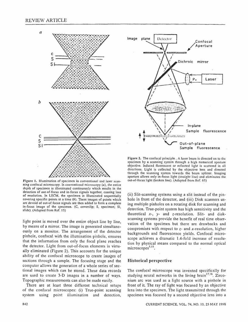
Confocal microscope generates information from a well-defined optical section rather than from the entire specimen, thereby eliminating the out-of-focus glare and increasing the contrast, clarity and detection sensitivity2
•12'13. Optical sectioning is noninvasive and
less time consuming compared to reconstruction algorithms to give 3-D images4
•11
·14-
16. Optical sectioning is achieved not only in the xy plane (perpendicular to the optical axis of the microscope) but also vertically in the xz or yz plane (parallel to the optical axisi·3·10
• With vertical sectioning, cells are scanned laterally (x or y axis) as well as in depth (z axis). Stacks of optical sections taken at successive focal plane (known as z series) are then reconstructed to generate a 3-D version of the specimen. The 3-D image can be directly visualized where each data point represents the quantity of specific contrast parameter used at a certain point in space. The image processing can be additionally used to enhance the confocal images. It is widely used in the fluorescence mode for different specimens and in bright field reflection mode for objects of different forms .
Principle of confocal microscope
The principle of confocal microscope was introduced by M insky 17
•18 . The method of image formation in confocal
microscope differs fundamentally from conventional wide field microscope (Figure I ). In conventional microscopy, the entire specimen is illuminated uniformly and simultaneously along the plane in whic h the objective lens is focused (Figure I a). This results in on outof-focus blur from orcas above and bclo\v the focal plane of interest, thereby reducing the {'Ontrnst and the resolution of image. Illumination in confocal microscopy, on the other hand, is not simultaneous but sequcntinl2'15'18. The illumination from a laser sourt·e is focused as a spot on one volume element of the specimen at a time ((iigure I b). i\ point light sourt'C is imaged in the pl:lnc of the object and the fluorescence emitted from the ohject is dircctctl to a photomultiplil' r through a detector pinhole. A computer displilys th<! p1,int as a pixel on screen. In ordl'r to produce a l'omph:tc im~tgl', the
REVIE\V ARTICLE
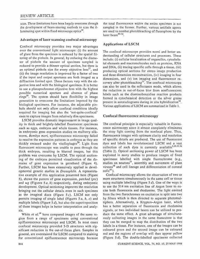
a
Figurt I. Illumination of specimen in conventional and laser scanning confocal microscopy. In conventional microscopy (a), the entire depth of specimen is illuminated continuously which results in the detection of out-of-focus and in-focus signals together. causing loss of resolution. In LSCM. the specimen is illuminated sequentially covering specific points at a time (b). These images of points which are devoid of out-of focus signals are then added to form a complete in-focus image of the specimen. (C, coverslip; S, specimen; Sl, slide). (Adapted from Ref. 15)
light point is moved over the entire object line by line, by means of a mirror. The image is generated simultaneously on a monitor. The arrangement of the detector pinhole, confocal with the illumination pinhole, ensures that the information from only the focal plane reaches the detector. Light from out-of-focus elements is virtually eliminated (Figure 2). This accounts for the unique ability of the confocal microscope to create images of sections through a sample. The focusing stage and the computer allows the generation of a whole series of sectional images which can be stored. These data records are used to create 3-D images in a number of ways. Topographic measurements can also be made easily.
There are at least three different technical setups of the confocal microscopes: (i) True-point scanning system using point illumination and detection,
842
Image
c=:;== /Confocal Aperture
mirror
Figure 2. The confocal principle . A lase.- bearn is directed on to the specimen by a scanning system through a high numerical aperture objective. Induced fluorescent or reflected light is scattered in all directions. Light is collected by the objective lens and directed through the scanning system towards the beam splitter. Imaging aperture allows only in-focus light (straight line) and eliminates the out-of-focus light (broken line). (Adapted from Ref. 65)
(ii) Slit-scanning systems using a slit instead of the pinhole in front of the detector, and (iii) Disk scanners using multiple pinholes on a rotating disk for scanning and detection. True-point system has high sensitivity and the theoretical x-, y- and z-resolution. Slit- and diskscanning systems provide the benefit of real time observation of the specimen but there are drawbacks and compromises with respect to z- and x-resolution, higher backgrounds and fluorescence yields. Confocal microscope achieves a dramatic 1.4-fold increase of resolution by physical means compared to the normal optical microscopes5
'15
•
Historical perspective
The confocal microscope was invented specifically for studying neural networks in the living brain11
•18
. Zirconium arc was used as a light source with a pinhole in front of it: The ray of light was focused by an objective lens into the specimen. The light transmiUed through the specimen was focused by a second objective lens into a
CURRENT SCIENCE, VOL. 74, NO. 10,25 MAY 1998
REVIEW ARTICLE
Dox 1. Confocal microscope
Confocal microscope is a versatile tool which permits the generation of 3-D images of biological and nonbiological specimens. A schematic presentation of the confocal micro· scope is shown in Figure 2. The instrument uses a high numerical aperture (NA) objective to focus the specific wavelength of a laser to a diffraction-limited spot on or in the specimen. An ordinary epifluorescence microscope is used for the purpose, with a semi-silvered mirror (for reflectance) or a dichroic mirror (for fluorescence) serving to introduce the illuminating beam into the microscope optical axis•. A pair of microcomputer-controlled galvanometer mirrors beyond the dichroic or semi-silvered mirror steer the spot over the object being viewed. Reflected or fluorescent light from the illumi· nated spot is returned and descanned by the same galvanometer mirrors, passed by the dichroic mirror, and focused on a pinhole in front of the detector- a low-noise photomul· tiplier tube (Figure 3). A beam splitter and a second photomultiplier permit dual wavelength fluorescence imaging and ratio measurements. Images are built up from the digit· ized photomultipliers. The images can be collected more rapidly by reducing the number of pixels and can be summed, subtracted from or added on to the stored images. A wide range of digital-image-enhancement methods includ· ing contrast stretching, false colour intensity coding and vari· ous image convolutions leading to edge enhancement or other forms of spatial frequency fi ltering can be applied. By integrating successive images, weakly fluorescent structures can be recorded with a sensitivity comparable to that of a silicon intensified camera.
The beam steering and photodetector apparatus are at· tached to the microscope in much the same way as an
second pinhole which was confocal (i.e. at the same focus) with the first hole. The light passing through the second hole was detected by a low-noise photomulti
plier. The basic configuration of the modern confocal mi
croscope is a lighter version of Minsky's microscope11·18, where the beam was stationary and the
specimen was moved on a vibrating stage. This optical arrangement had the advantage of scanning always on the optical axis, eliminating lens defects. However, this was used mainly in materials science and only to a limited extent in biological research because the vibratory movement caused wobble and distortion of the imagc
19•
An alternative to moving the specimen is to sc:ln the beam across the specimen which can be performed ei· ther by multiple beam scanning or by single beam scan·
. Th n . . lo ·' I . ntng. e y1ng-spot tmcroscope anu t 1c scanntng-mirror microscope21 arc nonconfocnl forerunners o f
beam-scanning confocal microscopes. The pioneers of multiple beam technology were inta
c:.ted in imaging the growing nerve cells in intact brain22• The tandem scanning rcOected light mil:roscope uses a bright white li ght source and a modified Nipkow disk to scan the specimen with hundreds of points of ligh t. The apertures of this disk were designed to match
CUJ<Rr.N'f SC IENCE. VOL. 74, NO. tO, 25 MAY I '1')8
Figure 3. The organization of the confocal microscope and the path of the laser beam.
ordinary video camera. The microscope is also equipped with a routine mercury arc epifluoreseence system to facilitate rapid location of the areas of interest by direct visual observation of a fluorescence image. A light collector can be mounted below the substage condenser, directing the transmitted laser light to a photomultiplier tube (PMT) through a fibre optic conduit (Figure 3). This way, ordinary bright field, phase contrast or differential interference contrast images of thin specimens can be collected for direct comparisons with confocal fluorescence or reflectance images.
the excitation and emission of the light path. The disk spins rapidly and acts as a point source, and a spatial filter prevents the out-of-focus light from reaching the photodetector, which can be the human eye or a sensitive video camera. The i mage viewed is the same as in conventional microscope and shows true colours of the
specimen23•
Fluorescence microscopy, using tandem scanning reflected light microscope, can be a practical option because of the presence of Nipkow disk and the improved efficiency ,of lightH. It is also easy to select different wavelengths of light, including UV and IR excitations, by optical filtering for multipnramctcr fluorescent imaging25. The microscope scans in :1lmost real time so that events such as exocytosis during fatilir.;lli~lll coulJ be obscrvcd26
•
Tandem SC:lnning confocal microscope rr~>dU\.'I!S CX·
tremely high resolution images, scanning f.1st enough t~> m:~kc the full image visibk llighly rdlectivc or lluorcsccnt specimens aml extremely bright light sourL·es n>ulJ only be used bcc:msc the aperture e:<dmks a high pmpurtion o f light. This diflieulty is uvL·rc;,)me by the usc of las'"·r illu111ination with 11 mc~·h:.wictlly sc:lnucll Sp~'L'illiCiliU whidl, hoWC\"Cr, illlp\•SCS limit~ Oil the 111:1\S
nnJ St:lbility of the pr~·pal'illiOII ;tn.l 1)11 the speed of thl!
REVIEW ARTICLE
scan. These limitations have been largely overcome through the development of beam-steering methods to scan the illuminating spot within fixed microscope optics14
•
Ad,·antages of laser scanning confocal microscopy
Confocal microscopy provides two major advantages over the conventional light microscope: (i) the amount of glare from the specimen is reduced by the spatial filtering of the pinhole. In general, by reducing the diameter of pinhole the amount of specimen sampled is reduced to provide a thinner optical section, but there is an optimal pinhole size for every objective lens27
, and (ii) the image resolution is improved by a factor of two if the input and output apertures are both imaged as a diffraction limited spot. These factors vary with the objective lens and with the biological specimen . It is better to use a planapochromat objective lens with the highest possible numerical aperture and absence of phase rings28
• The system should have flexibility in image generation to overcome the limitations imposed by the biological specimens. For instance, the adjustable pinhole should not only allow confocal conditions ideally required for imaging but also the 'not-quite-confocal' ones to capture images from relatively dim specimens.
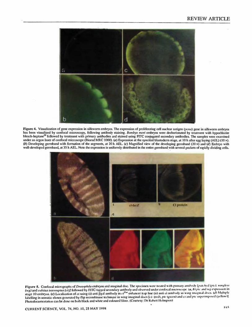
LSCM provides dramatic improvement in image quality in thick and brightly-labelled fluorescent specimens such as eggs, embryos and whole tissues. For instance, in embryonic gene expression studies on mulberry silkworm, Bombyx mori, epifluorescence microscopy failed to resolve the expression patterns in embryos as they are thickly encased under the vitellophages29
• Light from fluorescent microscope was unable to pass through the thick embryos, resulting in blurred images, but this problem was overcome by LSCM. The optical sectioning of the embryos permitted visualization of the domains of gene expression in germband (Figure 4). Further, LSCM has been extensively applied in developmental genetic studies in Drosophila. A representative example of this application presented here (Figure 5), shows the pattern of gene expression, patched (pte) and wg (Figures 5 a, b) respectively, during embryonic development. Optical sectioning improves the resolution bringing out the cellular details even in such specimen as the imaginal discs (Figure 5 c). LSCM not only permits imaging of single label (Figures 5 a, b, c) and multiple labels (Figure 5 d), but also the superimposition of these images helps in better interpretation and analysis.
White et al. 14 have compared images of the same region from a range of specimens using conventional epifluorescence microscope and LSCM. In most cases confocal microscopy provided 3-D structures with significant reduction in the out-of-focus glare. Samples in general, are overstained for LSCM compared to staining for conventional epifluorescence microscopy because
844
the total fluorescence within the entire specimen is not sampled in the former. Further, various antifade agents are used to combat photobleaching of f!uorophore by the laser beam3
0-32
•
Applications of LSCM
The confocal mkroscope provides novel and better understanding of cellular structures and processes. These include: (i) cellular localization of organelles, cytoskeletal elements and macromolecules such as proteins, RNA and DNA, (ii) tracing specific cells through a tissue, (iii) producing optical sections for ster~o image production and three-dimension reconstruction, (iv) imaging in four dimensions, and (v) ion imaging and fluorescence recovery after photobleaching33
• The confocal microscope can also be used in the reflectance mode, which allows the reduction in out-of-focus blur from nonfluorescent labels such as the diaminobenzidine reaction products formed in cytochemical detection or the silver grains present in autoradiograms during in situ hybridization34
.
Various applications of LSCM are summarized in Table I.
Confocal fluorescence microscopy
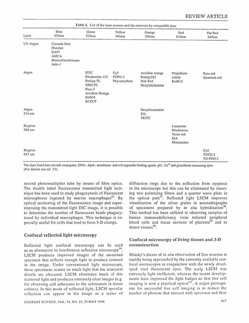
The confocal principle is especially valuable in fluorescence microscopy since it almost completely eliminates the stray light coming from the nonfocal pl~ne. Thus, fluorescence images with optimum clarity and resolution of specific details are produced. The use of fluorescent dyes and labels has revolutionized LSCM and a vast collection of such dyes is currently available5•2~·35 ·36
(Table 2). Optical sectioning power of LSCM has been exploited in many studies to produce images of fixed specimens labelled with single fluorochrome (e.g., studies on neurons37
, assembly and movement of plant viruses38 and cell lineage and differentiation of corneal celts39
) .
Confocal microscopy allows the observation of two or more structures simultaneously in the same cell or tissue using multiple labelling (Figure 5 d). One of the ways is to use the 514 nm excitation line of Argon laser to excite both fluorescein and rhodamine. The light emitted from the two flurochromes on excitation is split into two by 1ilters which is then directed to separate photomultipliers. Alternatively, a Krypton-Argon laser, which has a better separation of fluorescein and rhodamine signals, or two individual lasers can be utilized to produce the same effect. A great adv!lntage of simultaneously collecting images in the same framestore is that they can be merged to map the distribution of the two labels in a tissue. For instance, one of the images can be coloured green and the second image can be coloured red and the regions of overlap will then appear yellow (Figure 5 d). The double-labelled specimens collected
CURRENT SCIENCE. VOL. 74. NO. 10,25 MAY 1998
REVIEW ARTICLE
Figure 4. Visualization of gene expression in silkworm embryos. The expression of prol iferating a:U nuclenr antigen (pc:nu) gene in silkworm embryos has been visualized by confocal microscopy, following antibody struning. Bombyx 11Wri embryos were dechorioroted by treatment with hypochlorite bleach-heptane29 followed by treatment with primary antibodies and struned using me conjugated secondary antibodies. The samples were examined under an argon laser of confocal microscope (Biorad MRC 1000). (a) Expression at the syncitial blastoderm stage, at 10 h after egg laying (AEL) (10 x). (b) Developing germband with formation of the segments, at 20 h AEL (c) Magnified view of the developing germband (20 x) and (d) Embryo with well-developed germband. at 35 h AEL. Note the expression is uniformly distributed in the entire germ band. with several pockets of rapidly dividing cells.
Figurt s. Confocal micrographs of Dmsot•lulu emhryos untl unaginal dt~C. The S!'<-.:iult'n ~"''" uo:att'tl ~ ith rlllu.try Ullllt•<>·l~ u~"' Ju·J (/'1<'1. "'"'XI<~$ (M'J:} and cubitus illluruptus (d}/ followt'd by F1TC-t<lfgctl seculklary autihndy uutlull•rrvetl un•lt'r n•nf • ..-alttm·..,,..,,,.., 111.1>1 rt.· ""'' b·.~ "'1''-'»lllfl m
1t3ge 10 emhryos. (c) Localit.atinn of ,., u£ing (i) umi jjgal nntibu.ly in ,-r"" enhanrcr trap line (ii) anti d !ulltl••"'>' 111 "'~~~!: 1111.1~111.11 ,h,.:~. (J) MulttJ•k Jahelling in liOtnatic cluncs genl'fal.:d by flip rccombina:.c techni4uc in wing imaginal di.rs (t'i- (ro:Jl.t•t•· (fl\'t:n) Uthl • 1 ;ut.l r•t<' supo:ntiii''""J l)dlll\\ 1(.
PhuiQdocumentation can be done on buth black and white and colourco.l f1l111s . (Coun~·s)•: J'>r Kol'<'n llullll}!rt·n>
CURRENT SCIENCE, VOL. 74. NO. 10. 2S MAY I 'J91!
REVIEW ARTICLE
Technique
Confocal rcflccceJ light microscopy
Confo.-al fluNescence microscopy
Laser scissors and tweezers
Atomic force microscopy
Interactive laser cytometer
Table 1. Applications of the lllser scanning confocal microscope
Applicalion
Imaging unstained specimen
FISH in thick samples and sections Single !:~bel Multiple label Cytogenetics and chromosomal analysis 3-0 reconstruction of live tissue Time lapse Photoactivation of caged compounds FRAP Cell-cell communic~tion
Chromosome surgery/micro-dissection Mitosis and motllily of cell Cell membrane mechanics and cell fusion Reproductive biology: Sperm and oocyte manipulation Preembryo manipulation, In viv() manipulation of internal cell organelles Macromolecular imaging
Membrane potential in single cells Anisotropy in cell membranes Diffusion of membrane components and cytoplasmic structures Ion concentratiom and imaging in cells Ratiometric ion measurements in cells Statistical analysis of immunofluorescence at the level of single cells Cell sorting Multi well screening for fluorescence quantitation in cell cultures Analysis of anchored cells for enzymatic induction in situ
this way are prone to bleed through from one channel to the other and therefore require careful specimen preparation. However, this can be rectified in a variety of ways by digitally subtracting the bleed through of one image in the other, or by using newer dyes whose excitation and emission spectra are better suited to the Iaser32
• This method has been successfully applied for the localization of human growth hormone to a subset of cytoplasmic vesicles in PC12 cells40 and the determirnation of gene expression during wing development of Drosophila41
•
647 nm line of the Krypton-Argon laser are currently available32
·44
. Imaging at these longer wavelengths. provides improved viability of live samples and deeper penetration into the sample5
•
In situ hybridization technique has been exploited in various model systems for the detection of nucleic acids within the cells and tissues. LSCM has been successfully employed in conjunction with in situ hybridization to analyse the spatio-temporal profile of gene expression35.45-49, genetic di versity47
, cytogenetic and chromosome analysis5o.s1
•
Another improvement for double-labelling is to use two different excitation wavelengths which are sufficiently separated. This is possible either by using a single laser and changing filter blocks, and digitally realigning the images42 or by using two Krypton-Argon lasers which give good separation of fluorescein and rhodamine43
• Moreover, the Krypton-Argon laser has a third major line at 647 nm (red) and, therefore, different tluorochromes can be imaged simultaneously with a single laser. In fact, new dyes that are excited around
846
A nonconfocal transmitted light imaging can .also be generated with LSCM52
. This is extremely useful for image display purposes where a fluorescence image can be merged into a transmitted light image. In many cases, the fluorescence image alone is difficult to interpret without reference to the transmitted light image. The transmitted light image produced by the LSCM can be bright field, phase contrast, DIC or darkfield. The transmitted light detector collects light that passes through the specimen and then pipes it up on to the
CURRENT SCIENCE, VOL. 74. NO. 10, 25 MAY 1998
REVIEW ARTICLE
Table 2. List of the laser sources and the emission by compatible dyes
L:lser
UV-Argon
Argon
Blue 450nm
Cascade blue Hoechst DAPI AMCA Monochlorobimane Indo- I
Green 530nm
Yellow 560nm
Cy3
Orange 590nm
Red 610nm
Far Red 640nm
FITC Rhodamine 123 Bodipy FL NBD-PC Fluo-3
POP0-3 Phycoerythrin
Acridine orange Bodipy581 Nile Red Hexylrhodamine
Propidiumiodide Red613
Fura red Quantum red
Argon 514 nm
Krypton 568 nm
Krypton 647 nm
Acridine Orange DiOC6 BCECF
Hexylrhodnmine OiL TRITC
Lissamine Rhodamine Texas red DiA Mitotracker
CyS TOT0-3 TO-PR0-3
The dyes listed here include conjugntes, DNA-, lipid-, membrane- and cell organelle binding ngents, pH , ca•2 nnd glutathione measuring dyes. (For detnils see ref. 32).
second photomultiplier tube by means of fibre optics. The double label fluorescence transmitted light technique has been used to study phagocytosis of fluorescent microspheres ingested by murine macrophages53
• By optical sectioning of the fluorescence image and superimposing the transmitted light DIC image, it is possible to determine the number of fluorescent beads phagocytosed by individual macrophages. This technique is especially useful for cells that tend to form 3-D clumps.
Confocal refl ected light microscopy
Reflected light confocal microscopy can be used as an alternative to interference reflection microscopy~4 • LSCM produces improved images of the unstained spec imen that reflects enough light to prodm:c contrast in the image. Under conventional light micrusc0pc, these specimens scatter so much light that the structur:tl details arc ohscured. LSCM eliminates much of this scnttercd light and produces extremely clear images (e.g. for observing cell adhesions to the substratum in tissue culture). In thi ~ mode of rcllccted light, LSCM spcculJr reflection can nppcar in the irnogc as a series of
CURHENT SCIENCE:, VOl~. 74, NO. 10,25 MAY 199>!
diffraction rings due to the reflection from eyepiece in the microscope but this can be eliminated by inserting two polarizing filters and a quarter wave plate in the optical path11
• Reflected light LSCM improves visualization of the silver grains in autoradiographs of specimens prepared by in situ hybridization36
•
This method has been utilized in observing samples of human immunodeficiency virus infected peripheral blood cells and tissue sections of placentass and to detect virusess6•
Confocal microscopy of li\'ing tissues and 3-D reconstruction
Minsky's dream of in situ observation of live neurons is rapidly heing :tpproochcd by the currently avaibbk confocal microlocopcs in conjunction with the newly ~okvelopcd vit:l l lluoresccnt dycs. The early LSC~t was cxtrt:mcly light indTieicnt, whaeas thc recent dcvc:lopmc:nts have improved the light buJgc-t so that live l"l'll
imaging is nnw a pr:tctkal option~·5 • A major prcrequi· site for sucn:ssful live cd l im:tging is to r~:Jul"C the nurnhcr (lf photons that intcna~.· t with specimen and then
REVIEW ARTICLE
to use all the photons leaving the specimen to produce an imace. This is because living cells. especially when
~ 57 Th fluoresccntly labelled, arc prone to pbotodamage . e impro,·ements include scanning mirrors with better light efficiency {99~). and enhanced digitized images with a fast photon-counting mode.
Different approaches for observing living cells and tissues using the LSCM have been developed. One of them is to include static imaging of unfixed material either with reflected light or using epifluorescence. This technique has been applied for tracing the pathway of labelled peptides through the cornea40
, visualization of the endoplasmic reticulum in the plants using vital dye DiOC6~8, and the movement of antiproliferative heparin derivatives into rat smooth muscle cells59
• Another approach is the use of reporter genes. The introduction of the gree n fluorescent protein (GFP) as a reporter coupled with LSCM has revolutionized the scenario of livecell-imaging in the modern biological research. GFP has generated enormous interest among researchers studying gene expression in transgenic plant and animal model systems.
There is a tremendous advantage in 3-D image construction from optical sections of LSCM compared to the physically sectioned specimens. The 3-D data sets can be transferred directly into a 3-D reconstruction programme that runs on a graphic workstation. After a relatively trivial file reorganization, they are processed into a 3-D image which can be rotated or dissected on the screen of the graphics computer in a short time1
6.47.60. There are two basic methods currently appli
cable to the display of confocal data sets- volume reading 13 and geometric surface rendering61
• The 3-D reconstruction permits the imaging of vitally stained tissues without damaging the specimen by physically cutting sections.
Time lapse has been used for imaging changes in structure of single optical sections or z series with subsequent graphic reconstruction of each time point, sometimes referred to as 4-D imaging. Programmes are now available which automatically collect optical sections over time and store them on a large hard disk or optical disk recorder. These programmes also allow the entire series or individually selected optical sections to be played back over time. This is useful in following a particular strucwre that moves in the z plane over time. An example of time lapse using the LSCM is the recording of Golgi dynamics in cultured rat hippocampal astrocytes which are labelled with a vital dye which showed both tubulovesicular processes, and small submicron particles emerging from the trans Golgi and migrating along the microtubules61
• Further, laser photobleaching experiments showed that tubulovesicular processes can provide direct pathways for the d_iffusion of membrane lipids between joined trans Golgi e lements63.
M48
Confocal ion imaging
Confocal microscopy is advantageous for imaging ions such as calcium because the narrow depth of field allows better visualization of intracellular details by eliminating out-of-focus signals. Besides, the measurement errors due to path length variation are minimjzed since only a small and constant volume of the cell is sampled through the focal plane. Fast events are imaged using a smaller region, or a point in the specimen. Various fluorescent dyes, which change their fluorescence intensity relative to the concentration of free ions especially calcium, are now available64
• The dyes available earlier (e.g. FURA-2), were excited at relatively short wavelengths but most of the earlier versions of LSCMs were not equipped with UV source. However, excitation of the shorter wavelength dyes was achieved using two-
1 . fl . 61 I photon aser scanmng uorescence mtcroscopy · a -though the laser tends to be prohibitively expensive for routine work64
·6s.
Two-photon excited fluorescence is another major advancement in microscope-based laser manipulation6
•7
• In the conventional fluorescence microscopy, the absorption of a photon excites each fluorescing molecule to a higher energy state, from which the emission of one photon occurs when it returns to ground state. In the two-photon mode there is simultaneous absorption of two laser photons at the desired wavelength from the intended fluorophore. The only point . in the cell/organelle at which the photon intensity is high enough to result in two-photon absorption is ~he intense foca\ point of the laser beam. Since the molecule absorbs two photons virtually simultaneously, it behaves as if a single photon at half the wavelength of the impinging photons is absorbed, leading to fluorescence emission at a wavelength shorter than excitation wavelength. The two-photon fluorescence was initially developed as an analytical fluorescence technique but it can be used to induce photochemical events at the cellular and subcellular levels. Multiphoton-induced focal plane specific photochemistry could become a powerful tool in future to induce or to suppress site-specific photochemical processes in cells.
Various ion-sensitive dyes which are excited at longer wavelengths and better matched to the argon laser are now available. They include FLU0-3, RHOD-2, calcium green, calcium orange, calcium crimson, FURA-Red for calcium, SNAFL. SNARF, and BCECF for pH measurements66
'67
Other applications
LSCM also permits photoactivation of caged com· pounds68
, which provides a rapid method for releasing :1
specific compound as a discrete spot within a single cell. A short burst of UV breaks the chemical bond of the
CURRENT SCIENCE. VOL. 74, NO. 10, 25 MAY 199E
caged probe, releasing thereby the biologically active substance. Because UV is required for the photolysis, cells are often colabelled with a fluorescent probe, which can be monitored subsequent to the uncaging. Many of the current caged probes such as Nitr5, Diazo-2, IP3 and EGT A induce calcium responses which can be monitored by colabelling with Fluo-3, calcium green and fura red.
Fluorescence redistribution after photobleaching (FRAP) is another important application of LSCM for monitoring the recovery of fluorescence following the photochemical destruction of fluorophores within a small localized area69
• FRAP enables the monitoring of lateral diffusion of fluorescently-labelled molecule in or on a single cell, and is frequently used to quantitate the rate and extent of diffusion of fluorescently-labelled lipids or proteins across the cell- or nuclear-membranes.
LSCM is also used in measuring the efficiency of cell-cell intercommunication70
• This is based on the principle that intercellular gap junctions allow lowmolecular weight molecules to diffuse between two live cells which are in direct contact with each other. There will be recovery of fluorescence within a cell following photochemical destruction of the fluorochrome. Photobleached cells, which are connected to nonphotobleached cells by functional gap junctions, will exhibit fluorescence recovery.
LSCM has also been exploited in various cell biological approaches such as the study of membrane potential71, immunofl uorescence12 at single cell level, anisotropy of cell membranes73
, diffusion of membrane d I . 74 d . . components an cytop asmtc structures an rn sttu
analysis of enzymatic induction in anchored cells75•
Limita tions
A limitation of the present-day confocal microscope is the speed of data acquisition (time for scanning the laser across the preparation and for writing the data to the disk) and therefore, unsuitable for the study of phenomena changing in a rapid time scale. Cell development in cultures can be followed with the 3-D image acquisition in 0.5 to I min and in two dimension at considerably faster rates. Although a laser scanner can form an im::.gc in I to 4 sec, nearly all biological samples require multiple scans before the signa l to noise ratio becomes good enough to produce high quality images. Thus the real time for image acquisi tion in LSCM may be I min or longer. The speed of laser scanning will probably increase to acquire as m::.ny as 30 images per sec. The choice will be the white li gh t-ha~cd systems l' ecausc they offer a wide range of excitation wavch:ngths anJ necessary !>peed of data acqui~>ition.
Another ba~ic problem of LSCM is that the UV epilluon:s(;cncc objectives Me <ksigncc..lto tnaximi1.e UV transnai,~ion anJ are made achromatic for visible wave-
CUHI< ENT SCil; !'JC!:, VOL. 74. NO. I 0, 25 M A Y IIJ'JI:!
REVIEW ARTICLE
Detection focus Excitation focus Detection focus
Figure 6. The limitations faced by LSCM. Line drawing demonslrat· ing the phenomenon of (a) Lnternl- and (b) Axial-chromatic aberration.
lengths. When a laser beam is scanned through an objective, this inherent limitation causes lateral chromatic aberration, a situation in which objective focuses the UV laser illumination off to the side with respect to the visible fl uorescence deletion spot (Figure 6 a). As the laser beam is scanned off-axis, both signal intensity and resolution decrease76 effectively, limiting the useful fie ld of view.
LSCM can also suffer from axial chromatic aberration, a vertical displacement of the UV laser illumination spot in relation to the point of visible fluorescence detection76
• Since all the objectives used in LSCM focus the UV excitation light at a different depth than the visible detection light, the signal originating from the point of excitation will not be in proper focus for detection. The situation results in a marked loss of sensitivity, becoming worse as thinner and thinner optical sections are selected for imaging (Figure 6 b).
Application in biomedical field and future developments
A versatile microscope workstation known as confocal ablation trapping system (CATSZ), composed of two trapping laser beams anJ one abl:\tion heam, has been developed around a confoca l micros~l'Pe. The ~urrent generation of instruments arc uscJ in novel ways with potcnti:.ll for dcvclll[HllCnl into dinil·al instruments including confocal opthalmos~.:opc anJ cunfocal scrl·ening S)'~tem for in situ hyhriJinllions involved in br)'l' l)'p· ing. The conf,Kal im:lt'cS couiJ be hdpt'ul in 11\llr..: :•.:curate diagnosis. Optica l Sl'l'til>ning propl·rty t'f n>nf,,l·:•l mkrm.cope is coruing up :Is a rl·pt.,,·cnal·nt II> the t:r) \l·
or ultr;llhin-scction.; in p:atlaoh><'Y blwr .ttllt i1.'S. Thl! t'P· timal the o f thl· 3-1> l'•lllf,H.:al d.tt.t is bdi .:w.l It> h•rm tla.; basis for strm·tunal an.llr"i" uf th.: hi1llllgica l 1•bj1!1.'t" in th..: future. Till· J' l op.:-ny 111' cqu.tl tm.1gi11g ~.·undtti ll iiS
REVIEW ARTICLE
IN all data points in on-axis confocal systems may prnvc tn t-c very imponant for that. diagnostic research, '' hu:h at pre);e nt extensi vcly depends on sectioning of the matcrr.l l .: l)upled with histochemical examination, will rl!ly l'n LSCM. Another possible appl ication of LSCM tn future can be in optical biopsy (the use of 1:\ ~er-tndw.:d tluore:;.:ence and other spectroscopic methods to identify biochemical constituents in tissues) and in moni tori ng pho tosens itizers immediately before or during photodynamic cancer therapy procedures.
Advances may inc lude more sophisticated computational and imaging software that will aid in manipulating the enormous data to construct volumes rendered three dimensionally in rea l time for living specimens. The areas of application of LSCM are expanding with the introduction o f new probes for biomedical research . Further developments in the design of sensitive dyes and spec ific probes for use in confocal microscope will permit cell biologists to e)(.plore subtle relationships between cellular structures and function quantitatively in a dynamic volume . Less expensive and more compact laser equipment will possibly become available in the near future .
Nondamaging, high resolution techniques for imaging molecular structures in aqueous solutions continue to be developed and improved_ Scanning probe microscopy (e .g. atomic force microscopy) is emerging as an important technique for macromolecular imaging and manipulations to enable imaging structures and to examine their mechanical properties 17•
Mention should be made about laser tweezers and laser scissors, a laser trap device that enables the application of known forces to micrometer to submicrometer particles even within the cells . These two noninvasive techniques can be combined to provide cell biologists with the capabilities to hold (tweezers) and to cut (scissors) individual cell and organelles78• Their earliest combined use was to induce cell fusion by first holding and positioning two cells with laser tweezers, and then cutting the adjoining cell membranes with laser scissors. The other critical applications are in the area of biophysical and molecular mechanics including motor functions and polymer unfolding. Laser scissors and laser tweezers are currently available to do microsurgical ablations and chromosome surgery or dissections78
,
oocyte and sperm motil ity studies and preembryo manipulations19. They can also be used to spatially organize components in vitro to reconstitute cellular functions which require correct juxtaposition of the components_ Greatest changes and optimization in the techniques are e)(pected in the ne)(t ten years, which might allow real time analysis even in complex samples.
I. Inoue. S .. in Tht Handbook of Biological Confocal Microscopy (ed. Pawley, J. 8.), IMR Press, Madison, 1986, pp. 92-97_
2. Shotton. D. M. , 1. Ct/1 Sci., 1989, 94, 175-206.
8SO
3. Wilson. T.. in Confocal Microscopy, Academic: Preu, Su Diego. 1990.
4 Paddock. S. W., Lusu Scanning Confocal Microscopy. 1994, pp. 772- 779.
5. Paddock . S. W .. Proc. Soc. Exp. Bioi. Mtd .• 1996, 213, 24-31. 6. Denk. W., S trickler. J. H. o.nd Webb, W. W., Scitnct. 1990,
248. 73-76. 7 . Denk, W., Stricker. J. H. 3/ld Webb, W. W .• in Tht HIUldbooA: of
Biological Cnnfocal Microscopy (ed. Pawley. J. 8 .), Plenum Press, NewYork, 1995, pp. 444-4S8.
8. Poole. D., J. Cell Sci., 1992, 103, 1101-1110. 9. Schallen, G. and Pawley. J. B., Scitnct. 1988,239, 164-165.
10. Br;~kenhoff. G. J., V;~n der Voort, H. T. M .. Van Spronsen, E. A .. Linnemans, W. A. M. ;~nd Nanninga, N .. in Mttltods in Cell Biology (ed. Pawley, J. B.). Plenum Press, New Yorlt, 1990, vol. 30. pp. 25-35.
II. Cheng, P. C. and Summers, R. G., in The H"ndbook. of Biologi""1 Confocal Microscopy (ed. Pawley. J. B.), Plenum Press, New York, 1990, pp. 175-195.
12. Squarzoni, S ., Cinti , C ., Santi, S .. V:~lmori. A. and Maraldl, N. M ., Chromosomu, 1994, 103, 381-392.
13 . Turner, J. N .. 1. £ . M. Tech . . 1990, 18, 1-90. 14. White. J. G .. Amos. W. B. and Fordham. M., 1. Ctll Bioi., 1987.
10! , 41 - 48. I S. Shirley, J. W .. Centonzi. V. E., Stricker. S. A., DeVries, P. J.,
Pnddock. S .W. and Schallen, G., in Mtthods in Ctll Biology (ed. M:llsumoto, 8 .), Academic Press, New York. 1993, vol. 38, pp. 1-38.
16. Junera, H. R .. Masson, C .. Geraud, G. and Hema.ndez-Verdun, D., 1. Cell Sci .. 1995, 108. 3427-3441.
17. Minsky. M .. US Patent #3013467. Microscopy Apparatus. 1957
18. Minsky, M .. Scanning. 1988, 10, 128-138. 19. Wijnaendts van Resand, R. W .• Mnrsman. H. J. B., Kaplan, R ..
Davoust, J .. Steizer, E. and Strickler. R. J., 1. Microsr:. (Oxford), 1985, 138, 29- 34.
20. Yoong, J. Z. and Roberts. F., Nature, 1957, 167, 231. 21. Wilke. V., Scanning , 1984,7, 88-96. 22. Petran. M .• Hardavosky, M .• Egger. D. and Galamtos, R. J., Opt.
Soc. Am., 1968.58, 661-664. 23. Paddock, S . W., 1. Ctll Sci., 1989. 93, 143-146. 24. Boyde, A .. Jones. S . J., Taylor, M. L .. Wolfe, A. and Watson, T.
F., J. Mlcrosc. (Oxford), 1990, 157, 39-49. 25. Wright, S. J .. Walker, J. S., Shatten, H., Simerly, C., McCarthy,
J. J. and Shatten. G .. 1. Cell Sci .• 1989.94.617-624. 26. Terasaki. C., 1. Cell Sci .. 1995, 108, 2293-2300. 27. Holy, J., Simmerly, C., Paddock, S. W. nnd Schatten, G., J.
Electron Microsc. Ttch .• 1991, 17,384-400. 28. Keller. H. E .• in Tht Ha'ldbook of Biological Confocal Micros
copy (ed. Pawley, J. 8 .), Plenum Press. New York, 1990, pp. 77- 86.
29. Singh. A. and Gopinathan, K. P .. Curr. Sci .• 1997,72, 214-219. 30. Giloh, H. and Sedat, J. W., Scitnce, 1982, 217, 1252-1255. 31. Johnson. G. D .• Davidson. R. S .• McNamee, K. C., Russel, G .,
Goodwin. D. and Holborow, E. J., J. lmmu'lol. Mtrlwds, 1982, 55.231- 242.
32. Haughlond. R .. Handbook of Fluort.fcertt Prabu and Ru~arch Chemicals, Eugene or Molecular Probes, 1966.
33. Storrie. 8 ., Pepperltok. R., Stelzer, E. H. and Kreis, T. E .• J. Cell Sci., 1994, 107, 1307-13!9.
34. Robinson, J. M . ond Batten, B. E .. 1." Histochem.. CytoclleM., 1989, 37, 1761 - 176S.
3S. Pnddock, S. W., Mahoney, S ., Minshall, M .• Smith. L., Duvie, M. ond Lewis. D .. BloT~chniqrus. 1990. 11, 330-336.
36. Oknbe. T .. Teshimo, R., Furuno, T ., Tungoe, C., Sawada, J_ and Nakanishi. M., Biocltem. Biophys. RAts. Com~~UU~., 1996, 113, 245-249.
CURRENT SCIENCE, VOL. 74, NO. 10, 2S MAY 1998
37. Fine, A., Amos. W. B., Durbin. R. M. and McNaughton, A., TINS, 1988, 11, 346-351.
38. Cruz, S. S .• Chnpman. S., Roberts, A. G., Roberts, I. M., Prior, D. A. nnd Opnrka. K. J., Pmc. Natl. Acad. Sci. USA. 1996, 93. 6286-6290.
39. Beebe. D. C. and Mnsters, B. R., Invest. Opthatmot. Vis. Sci., 1996.37,1815-1825.
40. Schweitzer, E. S. and Paddock, S. W., J. Celt Sci., 1990, 96, 375- 381.
41. Skenth, J. B. and Carroll, S. B., Genes Dev., 1991, S, 984-995. 42. Fehon, R. G., Kooh, P. J .• Rebny. I., Regan, C. L., Xu, T.,
Muskavitch, M. A. T. nnd Artavanis-Tsakonas, S.,. Celt, 1990, 61, 523- 534.
43. Amdt-Jovin, D. J., Robert-Nicoud, M. and Jovin, T. M., J. Micrnsc. (Oxford), 1990, 157,61-72.
• 44. Schindele. D., Renzoni . G. E., Fearon, K. L. , Vandivor, M. W., Ekdahl, R. J. and Pepich, B. V., Cyrometry [Suppl], 1990, 4, 4.
45. Lichter, P .• Tang. C. C., Call, K., Hermanson, G., Evans, G., Housman. D. nnd Wnrd, D. C., Proc. Nat/. Acad. Sci. USA, 1990,85,9664-9668.
46, Bradt, J .• Hausmann, M., Ehemann, V. , Komitkowski, D. and Cremer, C .• J. Microsc. (Oxford), 1992. 168.47-57.
47. Amman, R., Snaidr, J .• Wagner, M .• Ludwig, W. and Schleifer, K. H .• J. Bacterial., 1996, 178, 3496-3500.
48. Minc-Golomb, D., Yadid, G., Tsarfaty, 1., Resau, J. H. and Schwartz, J. P .• J. Neuroclrem. , 1996, 66, 1504-1509.
49. Henderson, S .• Spector. D., Wang, S. S. and Harley, C., J. Celt Bioi., 1996, 134, 1-12.
SO. Linarez-Cruz, G., Millot, G., DeCremoux, P. . Vassy, J., Olofsson, B., Regaut, J. P. and Calvo, F., J. Histochem., 1995, 27, 15- 23.
51. Tanaka, K., Arif, M., Eguchi, M., Kumaravel, T. S., Ueda, R .• Ohno, R., lwnto, K .• Kyo. T ., Dohy, H. and Kamada, N., Leukemia 1997, 11,436-440.
52. Deitch, J . S .• Smith, K. L., Swann, J. W. and Turner, J. N., J. Electron Microsc. Tech ., 1991, 18,82- 90.
53. Hook, G. R. and Odeyale, C. 0 ., J. Leukocyte Bioi., 1989, 45, 277-282.
54. Mns ters, B. R. and Paddock, S. W., J. Microsc.(Oxfura), 1990, 158, 267-274.
55. Lewis, D. E., Minshnll, M .• Wray, M. P. H., Paddock, S. W .• Smith, L. and Crane, M. M., J. Infect. Dis., 1990, 162, 1373-1378.
56. Lizard et at., Histochemistry, 1994, 101. 303-3 I 0. 57. Harris, K. M. and Stevens. J. K .• J. Neurosci., 1989, 9, 2982-
2997. ' 58. Rojanasakul, Y. Y .• Paddock, S. W. and Robinson. J., Int. J.
Pharm .• 1990,61, 163-172. 59. Barzu. T ., Pascal, M. , Maman, M .• Roque, C., Lafont, F. and
Rousselct, A .• J. Cell Physiol., 1996, 167, 8-21.
CURRENT SCIENCE, VOL 74, NO. 10, 2~ MAY 19?!!
REVIEW ARTICLE
60. P1oton, D .• Gilbert, N .• Menages, M., Kaplan, H. and Adnet, J. J., J. Histochem. Cytochem., 1994,42, 137-148.
61. VanZandt, W. and Argiro, V., Unix Rev .. 1989, 7, 52- 57. 62. Savidge, T. C. and Jepson. M. A .• J. Celt Bioi., 1990, 111, 462a. 63. Cooper, M. S .• Cornell-Bell, A. H., Chernjavsky. A., Dani. J. W.
and Smith, S. J., Cell, 1990, 61, 135- 145. 64. Stricker. J., Dev. Bioi. 1996, 176,243- 263. 65. Mani, J., Biophotonics International, 1996,2,4- 7. 66. Dani, J . W., Chernajavsky, A. and Smith. S. J., J. Cell Bioi.,
1990,111. 389n. 67. Lemnsters, J. J., Chacon, E .• Ohata, H .• Harpe, I. S .• Meminen,
A. L., Tesfai, S. A. and Herman, B., Meth. Enz.ymol., 1995, 260. 428-444.
68. Adams, S. R. and Tsien. R. T., Annu. Rev. Physiot., 1993, 55, 755- 784 .
69. Chan. P. Y., Lawrence, M .• Dustin, M. L., Ferguson, L. M .• Golan, D. E. and Springer, T. E., J. Celt Bioi., 1991, 115, 245-255.
70. Albright, C. D., Grimley, P. M., Jones, R. T. and Resau, J. H .• J. Celt Bioi., 1988, 107,5547.
7 1. Bronner, C. and Landsey. Y. Biochem. Biophys. Acta, 1991, 1070, 321-33 1.
72. Dix. J. A. and Verkman. A. S., Biophys. J., 1990, 57, 23 1-240. 73. Liu, S. J., Sanders, M. E. and Hu, V. W., J. lmmunol., 1992,
142. 2370-2376. 74. Moutsatsos, I. K., Wade, M. H., Schindler, M. and Wang. J. L .•
Proc. Nat/. Acad. Sci. USA, 1987, 84, 6452-6456. 75. Yeh, G.C .• Lopaczynska. J .• Poore, C. M. and Phang, J. M .•
Cancer Res., 1992, 52, 6692-6695. 76. Wells. K., et at .• in The Ha11dbook of Confocal Microscopy (ed.
Pawley, J. B.), Plenum Press. New York, 1990. 77. Stout, A. and Webb, W. W .• in Methods in Celt Biology: Loser
Scissors and Tweezers (ed. Sheetz, M. P.), Academic Press, 1998, vol. 55, pp. 99-116.
78. Berns, M . W., Tadir, Y., Liang, H. and Trombcrg, B .• in Methods in Celt Biology: Loser Scissors and Tweezers (ed. Sheetz, M. P.), Academic Press, 1998, vol. 55, pp. 71-94.
79. Feigner, H., Groleg. F., Muller, 0. and Schliwa, M., in Methods in Cell Biology: Loser Scissors and Twuzus (ed. Sheetz, M.P.), Acndcmic Press. 1998, vol. 55, pp. 195-202.
ACKNOWLEDGEMENTS. We thnnk Dr Mndhuri Kango-Singh for help in the preparation of the mnnuscript, Dr Robert Holmgren for providing the confocal microgmphs of Drosopflila and the Gujarat Cancer Research Institute, Ahmedabad for providing confocnl mi\:roscopic facility. The work from our lab is supported by grants from the Depnrtment of Biotechnology. Govt. of India and the Indo-EEC Cooperation (project CII•-CT94-0092).
Received 27 Jnnuary 1998; revised accepted 6 April 1998