Conical axicons used as optical polar everters Louis Lavoie Franklin McLean Memorial Research Institute, Univer- sity of Chicago, Chicago, Illinois 60037. Received 28 August 1974. In this letter we offer some design equations for conical axicons used as polar everting prisms. McLeod, 1 Peters and Ledger, 2 Bryngdahl, 3 and Brunsden 4 among others have developed or applied axicons in one way or another. We will deal with just three of the several possibilities and combinations described by Brunsden et al. 4 : one that causes polar eversion and 180° rotation of the field and two that cause polar eversion without field rotation. Brunsden et al. propose several applications for these prisms, 4 including the construction of low-pass, high-pass, and band-pass filters for the optical Fourier plane or, more generally, gaining access to the center of a light beam with- out interfering with its outer parts. Another application cited is the efficient use of a laser's energy for cutting large diameter holes by transforming its solid beam to a thin an- nular beam. It should be emphasized, however, that some applications, as well as our treatment here, are for mono- chromatic, parallel light only. In the rod prism [Fig. 1(a)], the internal ray crosses the axis of rotation, causing a field rotation of 180°. Eversion without rotation may be achieved by preventing the ray from crossing the axis of rotation in the following ways: an axial hole may be bored and polished so that the ray at the resulting interface is totally reflected internally [the tube prism, Fig. 1(b)]; or the entrance and exit surfaces can be made concave so that the internal ray is refracted toward the outer surface where it undergoes total internal reflec- tion [the cup prism, Fig. 1(c)]. In the latter two cases it may be helpful to consider the prisms as similar to Dove prisms of rotation about either the longer or shorter paral- lel trapezoidal surfaces. 1482 APPLIED OPTICS / Vol. 14, No. 7 / July 1975
Transcript
Conical axicons used as optical polar everters Louis Lavoie
Franklin McLean Memorial Research Institute, University of Chicago, Chicago, Illinois 60037. Received 28 August 1974. In this letter we offer some design equations for conical
axicons used as polar everting prisms. McLeod,1 Peters and Ledger,2 Bryngdahl,3 and Brunsden4 among others have developed or applied axicons in one way or another. We will deal with just three of the several possibilities and combinations described by Brunsden et al.4: one that causes polar eversion and 180° rotation of the field and two that cause polar eversion without field rotation.
Brunsden et al. propose several applications for these prisms,4 including the construction of low-pass, high-pass, and band-pass filters for the optical Fourier plane or, more generally, gaining access to the center of a light beam without interfering with its outer parts. Another application cited is the efficient use of a laser's energy for cutting large diameter holes by transforming its solid beam to a thin annular beam. It should be emphasized, however, that some applications, as well as our treatment here, are for monochromatic, parallel light only.
In the rod prism [Fig. 1(a)], the internal ray crosses the axis of rotation, causing a field rotation of 180°. Eversion without rotation may be achieved by preventing the ray from crossing the axis of rotation in the following ways: an axial hole may be bored and polished so that the ray at the resulting interface is totally reflected internally [the tube prism, Fig. 1(b)]; or the entrance and exit surfaces can be made concave so that the internal ray is refracted toward the outer surface where it undergoes total internal reflection [the cup prism, Fig. 1(c)]. In the latter two cases it may be helpful to consider the prisms as similar to Dove prisms of rotation about either the longer or shorter parallel trapezoidal surfaces.
1482 APPLIED OPTICS / Vol. 14, No. 7 / July 1975
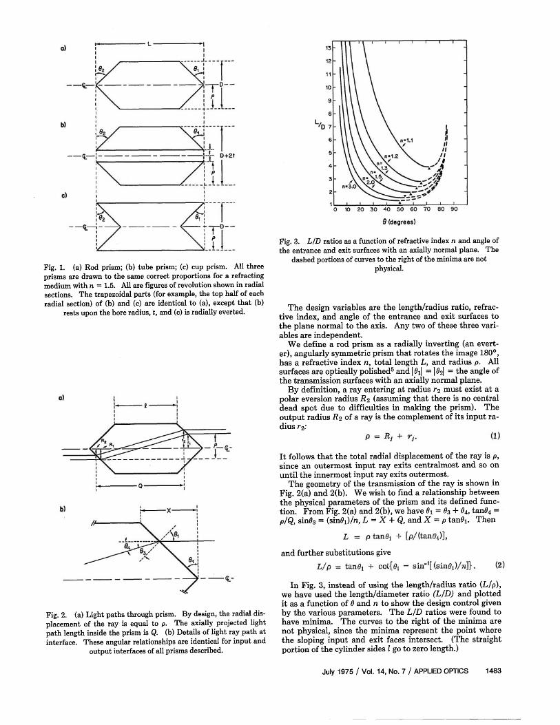
Fig. 1. (a) Rod prism; (b) tube prism; (c) cup prism. All three prisms are drawn to the same correct proportions for a refracting medium with n = 1.5. All are figures of revolution shown in radial sections. The trapezoidal parts (for example, the top half of each radial section) of (b) and (c) are identical to (a), except that (b)
rests upon the bore radius, t, and (c) is radially everted.
Fig. 3. L/D ratios as a function of refractive index n and angle of the entrance and exit surfaces with an axially normal plane. The
dashed portions of curves to the right of the minima are not physical.
The design variables are the length/radius ratio, refractive index, and angle of the entrance and exit surfaces to the plane normal to the axis. Any two of these three variables are independent.
We define a rod prism as a radially inverting (an evert-er), angularly symmetric prism that rotates the image 180°, has a refractive index n, total length L, and radius p. All surfaces are optically polished5 and |θ1| = |θ2| = the angle of the transmission surfaces with an axially normal plane.
By definition, a ray entering at radius r2 must exist at a polar eversion radius R2 (assuming that there is no central dead spot due to difficulties in making the prism). The output radius R2 of a ray is the complement of its input radius r2.
It follows that the total radial displacement of the ray is ρ, since an outermost input ray exits centralmost and so on until the innermost input ray exits outermost.
The geometry of the transmission of the ray is shown in Fig. 2(a) and 2(b). We wish to find a relationship between the physical parameters of the prism and its defined function. From Fig. 2(a) and 2(b), we have θ1 = θ3 + θ4, tanθ4 = ρ/Q, sinθ3 = (sinθ1)/n, L = X + Q, and X = ρ tanρθ1. Then
and further substitutions give
Fig. 2. (a) Light paths through prism. By design, the radial displacement of the ray is equal to p. The axially projected light path length inside the prism is Q. (b) Details of light ray path at interface. These angular relationships are identical for input and
output interfaces of all prisms described.
In Fig. 3, instead of using the length/radius ratio {L/ρ), we have used the length/diameter ratio (L/D) and plotted it as a function of θ and n to show the design control given by the various parameters. The L/D ratios were found to have minima. The curves to the right of the minima are not physical, since the minima represent the point where the sloping input and exit faces intersect. (The straight portion of the cylinder sides l go to zero length.)
July 1975 / Vol. 14, No. 7 / APPLIED OPTICS 1483
From inspection of Figs. 1(a) and 1(b), one finds that the length-radius ratios for the tube and rod prisms are identical, except that the tube prism has a radius increase equal to the bore radius t. Accordingly,
For the cup prism case, inspection of Figs. 1(a) and 1(c) shows that
and that no rotation occurs. Since these prisms are polar everting, there is an inter
esting emittance transformation of the incident radiation. Flux compression or expansion of the light occurs as a function of incident radius because the radial inversion (net eversion) implies area compression or expansion.
If a rod prism views a uniform field of parallel light and if its axis is parallel to the light rays, we may define (neglecting reflection and absorption) the transmission modulation coefficient 77 as the ratio of the output emittance w0 to the input emittance wi (Ref. 6) through the projected output and corresponding input areas, respectively. The projections, A0 and Ai, are of the output and input conical surfaces on a plane normal to the optic axis. If P is the transmitted radiant power, we have
The correspondence of the projected output and input areas is determined by Eq. (1) and (5):
Accordingly,
The various terms are shown in Fig. 2(a). The limits of integration are determined by the radial correspondence. Integrating Eq. (6) and substituting Eq. (1), we get
the limit of which as R1 approaches R2 is
or, in terms of the input,
The input emittance at a given r, multiplied by 77, gives the output emittance at the corresponding R.
In the case of uniform field illumination, we can see that the output emittance is greatest at the center, falling off inversely with R. If a bright axially centered spot is viewed, the output will be a ring of light, and conversely, a peripheral, axially centered ring will be transformed to a central bright spot.
The coefficient 77 is the same for the tube and cup prisms since the equivalent radial inversions occur (without rotation).
I thank Barry Brunsden for several interesting discussions as well as for bringing this problem to my attention.
The Franklin McLean Memorial Research Institute is operated by the University of Chicago for the United States Atomic Energy Commission (formerly the Argonne Cancer Research Hospital).
1484 APPLIED OPTICS / Vol. 14, No. 7 / July 1975
References 1. J. H. McLeod, J. Opt. Soc. Am. 44, 592 (1954); 50, 166 (1960). 2. W. N. Peters and A. M. Ledger, Appl. Opt. 9, 1435 (1970). 3. 0. Bryngdahl, J. Opt. Soc. Am. 60, 915 (1970). 4. B. Brunsden, R. Beck, and D. Charleston, "Optical Eversion:
Methods and Applications," Internal Report, McLean Institute, U. of Chicago (1974).
5. For the rod and tube prisms only the ends and the bore need be polished.
6. We take input emittance to mean the power per unit area radiated from the input surface into the prism.