118
Issued 2-2013 Version 2.06 DIGITAL PROJECT DEVELOPMENT MANUAL Version 2.06 CONNECTICUT DEPARTMENT OF TRANSPORTATION
| Date post: | 29-Aug-2018 |
| Category: |
Documents |
| Upload: | nguyentruc |
| View: | 213 times |
| Download: | 0 times |

Issued 2-2013 Version 2.06
DIGITAL PROJECT DEVELOPMENT
MANUAL
Version 2.06
CONNECTICUT DEPARTMENT OF
TRANSPORTATION

Connecticut Department of Transportation Digital Project Development Manual
Issued 2-2013 2 Version 2.06
INTRODUCTION
This document is for Consultant and State Employees responsible for the production or review of
digital contract plans, specifications, supplemental contract documents, and contractor submittals.
This document covers the development, review and commenting, and submission of digitally
signed contract plans in PDF format including revisions, the delivery of specifications in
Microsoft Word format, the delivery of supplemental contract documentation in PDF format, and
the delievery of contractor submittals in PDF format. This manual also includes sections on the
usability of these PDF documents.
Questions or inquiries regarding the subject matter can be forwarded to the following contacts:
William Pratt P.E.
Transportation Principal Engineer
AEC Applications
860.594.3320
Bruce Bourgoin P.E.
Transportation Supervising Engineer
AEC Applications
860.594.2760
Mathew Calkins P.E.
Transportation Engineer
AEC Applications
860.594.2988
Revision History
Version 1.01 Revisions – Issued 5/2011
Version 1.02 Revisions – Issued 6/2011
Version 1.03 Revisions – Issued 7/2011
Version 1.04 Revisions – Issued 8/2011
Version 1.05 Revisions – Issued 9/2011
Version 1.06 Revisions – Issued 12/2011
Version 2.01Revisions – Issued 4/2012
Version 2.02 Revisions – Issued 9/2012
Version 2.03 Revisions – Issued 9/2012
Version 2.04 Revisions – Issued 11/2012 – Clarified Section 1.4 Step 2
Version 2.05 Revisions - Issued 1/2013 – Section 4 – The sheets affected by Addendums and
Construction Orders must be X’d out after the Addendum or Construction Order is approved.
Version 2.06 Revisions - Issued 2/2013

Connecticut Department of Transportation Digital Project Development Manual
Issued 2-2013 3 Version 2.06
Table of Contents DEFINITIONS ............................................................................................................................................................. 5
DIGITAL CONTRACT PLANS, SPECIFICATIONS, AND SUPPLEMENTAL CONTRACT SECTION 1
DOCUMENTS ............................................................................................................................................................. 6 1.1 Final Design Document Deliverable ............................................................................... 6 1.2 Requesting a Digital Project............................................................................................ 6 1.3 Prerequisites and Policies ................................................................................................ 6 1.4 Format .............................................................................................................................. 7 1.5 File Naming .....................................................................................................................10
1.5.1 Contract Plans (discipline subsets) ............................................................................................................ 10 1.5.2 Specifications ............................................................................................................................................ 10
1.6 Contract Plan Drawing and Sheet Numbering.............................................................10 1.6.1 Drawing Number ....................................................................................................................................... 10 1.6.2 Final Plan Sheet Numbers ......................................................................................................................... 11 1.6.3 Addendum and Design Initiated Change Order Sheet Numbers ................................................................ 19 1.6.4 Adobe – Addendum and Design Initiated Change Order Sheet Numbers.................................................. 19 1.6.5 Bluebeam – Addendum and Design Initiated Change Order Sheet Numbers ............................................ 21
1.7 CTDOT For Information Only Sheets ..........................................................................23 1.8 CTDOT Standard Sheets ...............................................................................................23 1.9 Contract Plan Sheet Publishing .....................................................................................23 1.10 Example: Typ. Single Volume Digital Contract ...........................................................24 1.11 Example: Multiple Volume Digital Contract................................................................25 DIGITAL SIGNATURES FOR CONTRACT PLANS ...................................................................... 27 SECTION 2
2.1 Graphic Image of Signature ...........................................................................................27 2.2 Creating Graphic Image of Signature: .........................................................................28
2.2.1 CTDOT Staff:............................................................................................................................................ 28 2.2.2 For Consultant Staff: ................................................................................................................................. 29
2.3 Setting Digital Signature Appearance Preferences: .....................................................30 2.3.1 Adobe Signature Appearance .................................................................................................................... 30 2.3.2 Bluebeam Digital Appearance ................................................................................................................... 34
2.4 Watermarking Plans with Graphic Image of Signature ..............................................36 2.4.1 Adobe – Watermarking Plans with Graphic Image of Signature ............................................................... 36 2.4.2 Bluebeam - Watermarking Plans with Graphic Image of Signature (CTDOT and Consultant Designed) . 38
2.5 Digital Signature Fields ..................................................................................................41 2.5.1 Adobe - Creating Digital Signature Form Fields ....................................................................................... 42 2.5.2 Bluebeam - Creating Digital Signature Form Fields .................................................................................. 44
2.6 Applying Digital Signatures ...........................................................................................45 2.6.1 Applying Digital Signatures to 01_General Subset (FDP and Addendum Subsets) .................................. 45 2.6.2 Applying a Digital Signatures to 02_Revisions Subset .............................................................................. 47 2.6.3 All Other Discipline Subsets - Single Signature ........................................................................................ 48 2.6.4 Standard Drawing Subsets – Single Signature ........................................................................................... 48 2.6.5 All Other Discipline Subsets – Multi-Signatures ....................................................................................... 48 2.6.6 Working Drawings .................................................................................................................................... 49 2.6.7 Applying Digital Signature Workflows ..................................................................................................... 49
SUBMITTING DOCUMENTS TO CTDOT PROJECTWISE ......................................................... 55 SECTION 3
3.1 Final Design Plans, Specifications, and Supplemental Document Checklist .............56 3.2 Project Data Transmission .............................................................................................56
3.2.1 ProjectWise ............................................................................................................................................... 56 3.2.2 Projectwise Folders for Contract Documents ............................................................................................ 57 3.2.3 Uploading Documents - ProjectWise (Thin Client) ................................................................................... 58 3.2.4 Uploading Documents – Projectwise (Thick Client) ................................................................................. 61 3.2.5 Combining and Uploading Contract Specifications and CSI Special Provisions ....................................... 64 3.2.6 Uploading Supplemental Contract Documents .......................................................................................... 65 3.2.7 CTDOT Contracts Finalizing of Contract Specifications .......................................................................... 66 3.2.8 Notification of Submittals ......................................................................................................................... 66 3.2.9 Contract Plans Workflow (FDP - Advertise) ............................................................................................. 66 3.2.10 ProjectWise Project folder Security ........................................................................................................... 67 3.2.11 100_Contract_Plans (PDF) Folder (Dynamic Security) ............................................................................ 67 3.2.12 Changing the State of a Document ............................................................................................................ 68
CONTRACT PLAN AND SPECIFICATION REVISIONS (ADDENDA AND DESIGN SECTION 4
INITIATED CHANGE ORDER) ........................................................................................................................................ 70 4.1 Addenda ...........................................................................................................................70
4.1.1 Revised Plans - Addenda ........................................................................................................................... 70 4.1.2 New Sheets - Addenda .............................................................................................................................. 71 4.1.3 Adding New Subset – Addenda ................................................................................................................. 72 4.1.4 Voiding Sheets .......................................................................................................................................... 72 4.1.5 Addenda Plans Workflow.......................................................................................................................... 73 4.1.6 Addenda Specifications ............................................................................................................................. 74 4.1.7 Addenda Report ........................................................................................................................................ 74
4.2 Design Initiated Change Order (DCO) .........................................................................74

Connecticut Department of Transportation Digital Project Development Manual
Issued 2-2013 4 Version 2.06
4.2.1 Revised Sheets – DCO .............................................................................................................................. 75 4.2.2 New Sheets - DCO .................................................................................................................................... 76 4.2.3 New Subset – DCO ................................................................................................................................... 77 4.2.4 Voided Sheets............................................................................................................................................ 77 4.2.5 DCO Specifications ................................................................................................................................... 77
4.3 02_Revisions Subset ........................................................................................................78 4.3.1 02_Revisions Subset Workflow - Addenda ............................................................................................... 80 4.3.2 02_Revisions Subset Workflow - DCO ..................................................................................................... 80 4.3.3 Adding a New Revisions Sheet to the 02_Revisions Subset ...................................................................... 81 4.3.4 Filling Out Revision Index Sheet .............................................................................................................. 84
4.4 Placing Stamps on Affected Sheets – Revised, or Deleted Sheets ...............................84 AS-BUILT COMMENTS - FINAL PLANS ........................................................................................ 86 SECTION 5
5.1 As-Built Revisions (Digital Comments) Workflow ......................................................86 5.1.1 Post Construction As-Built ........................................................................................................................ 87 5.1.2 Active As-Built ......................................................................................................................................... 87
5.2 As-Built Markup of Contract Plans ..............................................................................87 5.3 Applying As-Built Comments to Contract Plans .........................................................88
5.3.1 Before Using Bluebeam for As-Builts ....................................................................................................... 88 5.3.2 Opening the Contract Plans from Projectwise ........................................................................................... 88 5.3.3 Applying Digital As-Built Stamps ............................................................................................................. 90 5.3.4 Applying Digital As-Built Notes ............................................................................................................... 94
5.4 Notifications .....................................................................................................................97 5.4.1 Completion of the As-Builts ...................................................................................................................... 97 5.4.2 Notifying Department Personnel ............................................................................................................... 97
CONTRACTOR SUBMITTALS ......................................................................................................... 98 SECTION 6
6.1 Working Drawings for Permanent Structures .............................................................98 6.2 Shop Drawings ................................................................................................................98 DIGITAL REVIEW AND COMMENTING ...................................................................................... 99 SECTION 7
7.1 Digital Review .................................................................................................................99 7.2 Commenting Tools ..........................................................................................................99
7.2.1 Bluebeam .................................................................................................................................................. 99 7.2.2 Adobe Acrobat ........................................................................................................................................ 103
7.3 Digital Stamps ...............................................................................................................104 7.3.1 Bluebeam Stamps .................................................................................................................................... 104 7.3.2 Adobe Stamps ......................................................................................................................................... 105
APPENDIX A 107 Initial Log into Bluebeam .......................................................................................................107 Downloading the CTDOT Bluebeam Profile .........................................................................112
APPENDIX B 114 Usability of PDF Documents ...................................................................................................114 Structure of Digital Plans ........................................................................................................114 Functionality of PDF Digital Plans.........................................................................................115
Digital Plan Levels .................................................................................................................................................... 115 Searching Digital Plans ............................................................................................................................................. 116 Measuring on the Digital Plans ................................................................................................................................. 117
Digital Specification Package ..................................................................................................118
Connecticut Department of Transportation Digital Project Development Manual
Issued 2-2013 5 Version 2.06
DEFINITIONS ACD – The attribute applied to a revision requested by the Processing unit to an ADP discipline
subset.
ACD2 – The attribute applied to a revision requested by the Processing unit to an ACD discipline
subset.
ADP – The attribute applied to an Addendum discipline subset.
DCD – The attribute applied to a revision requested by the Processing unit to an FDP discipline
subset.
DCD2 – The attribute applied to a revision requested by the Processing unit to a DCD discipline
subset.
Discipline Subset – A multi-page PDF document that includes all the contract plan sheets for a
discipline. Example would be all the structures sheets would be packaged in (1) multi-page PDF
document.
DCO – The attribute applied to a design initiated change order discipline subset.
DPD Manual – Digital Project Development Manual.
Engineer of Record – The engineer’s digital signature that is applied to the discipline subsets.
For CTDOT staff this would be the Principal Engineer.
FDP –The attribute applied to a final design plans discipline subset.
FIO – The attribute applied to a “for information only” discipline subset.
FPL – The attribute applied to an advertised FDP discipline subset
Project Manager – Lead designer on the project. For CTDOT staff this would be the TE 3 or
Supervisor of the lead discipline or consultant liaison TE3 or Supervisor.
Projectwise - CTDOT is currently using Bentley’s ProjectWise as a data management software
for digital projects. Projectwise allows the CTDOT, and authorized business partners to access its
data anywhere internet access is available. Projectwise shall be used by all consultant engineers
delivering digital contract documents.
STD – The attribute applied to the “CTDOT Standard Drawings” discipline subsets.
WDP – The attribute applied to working drawing submittals. This includes the plans,
calculations, or any supplemental documents in the submittal.
WDP2 – The attribute applied to a revised WDP submittal.

Connecticut Department of Transportation Digital Project Development Manual
Issued 2-2013 6 Version 2.06
Digital Contract Plans, Section 1
Specifications, and Supplemental
Contract Documents
1.1 Final Design Document Deliverable The following contract documents shall be submitted into Projectwise when delivering a digital
project, see Section 3 of this document for submittal procedures for the above documents: For
CTDOT designed projects each discipline is responsible for uploading their documents into
Projectwise.
Contract Plans
Contract Specifications
Supplemental Contract Documents - Include but not limited to the following:
o PW Submittal Checklist
o Proposal Estimate, with signed checklist
o Federal Estimate
o Calendar Day Estimate
o Final Design Report
o Categorical Exclusion
o Design Approval Letter
o Environmental Permits
o DBE/SBE Approval with percentage
o Commitment list
o Agreements
o Proprietary Item Approval
o Standalone Transportation Management Plan Document, taken from the final
design report
1.2 Requesting a Digital Project The following fill able PDF form must be completed and returned to AEC applications by State
Design or CTDOT Consultant Liaison personnel to request a digital project: ProjectWise Project
Request Form
1.3 Prerequisites and Policies 1. All contract plans prepared by a CT licensed Engineer or CT licensed Architect shall be
digitally signed in accordance with this manual. All contract plans, specifications, and
supplemental contracts documents will only be accepted by the CTDOT if they meet all
the requirements of this manual. Approval for additional development and testing of
digital documents and procedures shall come from the CTDOT Office of Quality
Assurance.
2. Digital contract plans, in the following stages: Final Design Plans (FDP), Design
Completion Data (DCD), Addenda, Addenda Completion Data (ACD), Design Initiated
Change Order (DCO), and Working Drawing (WDP) shall be digitally signed in
conformance with this manual.
a. Digital signatures must meet the requirements of Adobe’s Certified Document
Services (CDS).
b. CDS, and CDS vendor information is provided at the following
website: Uhttp://www.adobe.com/security/partners_cds.html UH
c. Trial CDS Signatures will not be accepted by the Department, a signature must
be purchased from one of the CDS Vendors.

Connecticut Department of Transportation Digital Project Development Manual
Issued 2-2013 7 Version 2.06
3. After contract plans have been advertised, the digital signature is not allowed to be
removed.
4. Standard Computer Aided Design (CAD) Applications shall conform to those listed
here HUhttp://www.ct.gov/dot/digitaldesignUH. 5. Use of digital signatures not conforming to the requirements of this manual must be
approved by both the Office of Quality Assurance, and the Office of Legal Services. 6. This manual is designed to be used with the latest CTDOT Digital Design Environment.
7. Digital Contract Specifications shall be prepared in accordance with the Departments
policies and procedures for Contract Development. 8. Supplemental contracts documents shall be submitted digitally in PDF format. See
Section 3.2.8 for supplemental contract document list and submission procedures.
9. The Consulting Engineer acknowledges and agrees that Contract Plans submitted using
the [Digital Submission Procedure set forth in this Manual] has the same force and effect
for the purposes of the Consulting Engineer’s agreement with the State as a signature and
seal of a Connecticut Licensed Professional Engineer or Architect as set forth in § 20-
300-10 of the Regulations of Connecticut State Agencies or § 20-293 of the Connecticut
General Statutes, as applicable. Nothing in this DPD Manual serves as an authorization
for, or endorsement of, the use of this [Digital Submission Procedure] generally by the
Consulting Engineer, its subcontractor(s), or any Connecticut Licensed Professional
Engineer or Architect with respect to other work it performs for the State or work it
performs for other clients.
10. Version 9.0 of Adobe Acrobat or Version 10.2 of Bluebeam were used in the production
of all figures and procedures in this manual.
11. When on call consultants are used for CTDOT projects, the title sheet shall be digitally
signed by CTDOT following the procedure in Section 2.6.1 of this manual.
1.4 Format 1. Digital contract plans (preliminary, semifinal, FDP, etc.), working drawing plans and
shop drawing plans shall be in PDF format; PDF Plans must be sized either 36” x 24” for
projects created before 6/2007 and sized 34” x 22” for projects created after 6/ 2007; PDF
plans shall be measurable to scale in the PDF; PDF plans shall be able to be printed to
paper and scaled appropriately; text must be searchable; and all levels must have the
ability to be displayed on or off, unless approved otherwise. All information on the
digital contract PDF plans shall have been created from MicroStation or an approved
alternate. The only information that shall be added to the plans using a PDF editing
software are as follows:
a. Sheet numbers (see Section 1.6.2)
b. Page labels (see Section 1.7)
c. Watermark (see Section 2.4)
d. Any digital signature fields (see Section 2.5)
e. Digital Signature (see Section 2.6)
2. Contract plans shall be grouped, by discipline into individual multiple page PDF files
called discipline subsets. Discipline subsets are not to be combined in a PDF
Package/Portfolio. Examples of discipline subsets are: 01_General, 02_Revisions,
03_Highway, 04_Bridge, etc. See Section 1.11 & 1.12 for more examples of discipline
subsets.
3. Plans For Information Only (FIO) shall be submitted digitally, in individual subsets
based on the entity providing the information, Amtrak, CL & P, AT&T, Designer etc.
These subsets do not require a digital signature, but each sheet in the subset shall be
labeled; “For Information Only”. The subset numbers shall be selected by the lead
designer so that the FIO subsets are last. Each sheet shall be numbered correctly, see
Section 1.6.2. Upload and attribute in accordance with Section 3.2.
4. Utility drawings shall be submitted in accordance with the following:
a. Utility plans For Information Only (FIO) shall be submitted in a utility subset
based on the utility company, AT&T subset, CL&P subset, etc. These subsets do
Connecticut Department of Transportation Digital Project Development Manual
Issued 2-2013 8 Version 2.06
not require a digital signature, but each sheet shall be labeled; “For Information
Only”. FIO utility subsets shall be numbered so that they are the last subsets.
Example Labels; 10_CL&P_FIO, 11_AT&T_FIO
b. Utility company designed plans that include work being done by the States
Contractor shall be submitted in a utility subset based on the utility company,
AT&T subset, CL&P subset, etc. These subsets do not require a digital
signature. Example Labels; 10_CL&P, 11_AT&T
c. Utility plans that are designed by Utility or State Consultants firms that include
work being done by the States Contractor shall be submitted in a utility subset
based on the utility company, AT&T subset, CL&P subset, etc., and shall be
digitally signed in accordance with this manual. Example Labels; 10_CL&P,
11_AT&T
5. See Section 3.2 for uploading and attributing Utility Plans. See Section 1.11 & 1.12 for
more examples of discipline subsets.
6. CTDOT Standard sheets shall also be delivered digitally. For each project always
download the standards from the CTDOT website to insure the most recent standards are
included in the project. The workflow Assembling_CTDOT_Standard_Sheets.pdf
explains how to obtain, create standard sheet subsets, and insert them into a digital
project. For submission of CTDOT Standard Sheets, see Section 3.2.
7. The first and second subsets in the project must always be the 01_General and
02_Revisions respectively. The Project Manager is responsible for determining the order
of all other discipline subsets, Sections 1.11 and 1.12 show examples.
8. Discipline subsets shall contain a maximum of 150 sheets.
9. Discipline subsets shall be published directly from a CAD application. Scanned images
or raster image formats will not be accepted.
10. Footers, displaying the sheet number, shall be placed on each page of each PDF subset.
See Section 1.6.2, “Sheet Numbering”
11. Each subset shall contain bookmarks; one for each page. Figure 1 displays an example of
bookmarks. See Publishing_MicroStation_Content_to _PDF_Format.pdf for more
instructions.
a. Figure 1 also displays examples of subgroup folders. While publishing,
subgroups may be created to contain similar sheets. See
Publishing_MicroStation_Content_to _PDF_Format.pdf for more instructions.
12. Levels with the appropriate CTDOT names shall have the ability to be displayed on or off
within the PDF document.
13. The first page of the subset 01_General shall be the CTDOT digital project title sheet
which includes an index of the subsets contained within the project, sheet count totals for
all subsets, a list of drawings for the 01_General Subset, and an area(s) reserved for
applying the digital signature(s).
Link to digital title sheet:
Digital Title Sheet
CTDOT engineers can find the digital title sheet in the seed files on our W: drive.
14. The 01-General subset shall include all detailed estimate sheets.
15. The 02_Revisions subset must be included in each digital project and there shall only be
(1) revisions subset.
16. Subset 02_Revisions shall contain only revision sheet(s), titled “Index of Revisions”, See
Section 4.3. These revision sheets are used for tracking all sheet changes due to addenda
and design initiated change order (DCO) with respect to the entire project. These sheets
are originally blank and unsigned, and shall be managed and updated as needed by the
Project Manager. The CTDOT Revision Contract Sheets can be obtained here:
CTDOT Designed Projects - 02-Revisions Subset
Consultant Designed Projects - 02-Revisions_CE_Subset
17. The first page of each subset shall be a subset cover sheet. This cover sheet shall contain
both; an index of drawings contained within the subset that includes both drawing
numbers and drawing titles and the form field place holder(s) which receives the digital
signatures. The following cell has a table for the index of drawings and the digital

Connecticut Department of Transportation Digital Project Development Manual
Issued 2-2013 9 Version 2.06
signature cell place holder BDR_Discipline_Cover Sheet cell. See figure 1 for an
example.
18. Digital Contract Specifications shall be submitted in MS Word format and in accordance
with the Departments policies and procedures for Contract Development. CSI special
provisions shall be submitted in pdf format.
a. For projects where a consultant is the Project Manager on the project, the
Specification and CSI special provisions submittals shall be submitted in (1)
zipped folder, see section 3.2.6.
b. For projects where a CTDOT design unit is the Project Manager on the project,
the Specification and CSI special provisions shall be submitted in individual
zipped folders per discipline, see section 3.2.6.
c. Design Initiated Change Orders shall be place in (1) pdf document, with “C#”
and the date in the header. An example would be “Rev. C1 - mm/dd/yy”.
19. Supplemental documents shall be 8.5” x 11” pdf documents, except the proposal estimate
which shall be in “.est” format. Documents that require signatures may be scanned with
a minimum resolution of 200 dpi, and size = 8.5”x11”. These documents do not need to
be digitally signed.
20. As-built information shall be digitally applied to the contract subsets by District
Personnel after the job is complete using Adobe Acrobat Professional or Bluebeam. See
section 4.5.
21. Working Drawing calculations shall be in (1) pdf document with a page size of 8.5” x
11” and be digitally signed in accordance with Section 2.6. Any supplemental documents
that are included in the Working Drawing submittal shall be 8.5” x 11” pdf documents.
Documents that require signatures may be scanned with a minimum resolution of 200
dpi, and size = 8.5”x11”. These documents need to digitally signed in accordance with
Section 2.6.
Using a discipline subset format streamlines both the development of contract plans and the
administration of the plans during preliminary design, FDP, DCD, Addenda, DCO and As-Built
submissions. Moreover, it also leverages the ability to digitally sign the individual discipline
based contract plan subsets per designer.
Figure 1 Discipline Subset Bookmarks, Index of Drawings, & Signature fields
See Section 2.5 for digital signature form field place holder cells.
Connecticut Department of Transportation Digital Project Development Manual
Issued 2-2013 10 Version 2.06
1.5 File Naming
1.5.1 Contract Plans (discipline subsets) The file name shall match the discipline subset name. For example, the 02-Revisions subset shall
have the file name 02-Revisions.pdf. However, this name will change during the uploading and
attributing of the file into Projectwise. See section 3.2 Project DataTransmission.
1.5.2 Specifications FDP and Addendum
These specifications shall be individual word documents placed in a zipped folder. CTDOT
processing shall combine all specifications into (1) PDF document and upload this into
Projectwise. See section 3.2.5.
Design Initiated Change Orders
These specification(s) shall be packaged in (1) pdf document and uploaded into projectwise. See
section 3.2.5.
1.6 Contract Plan Drawing and Sheet Numbering
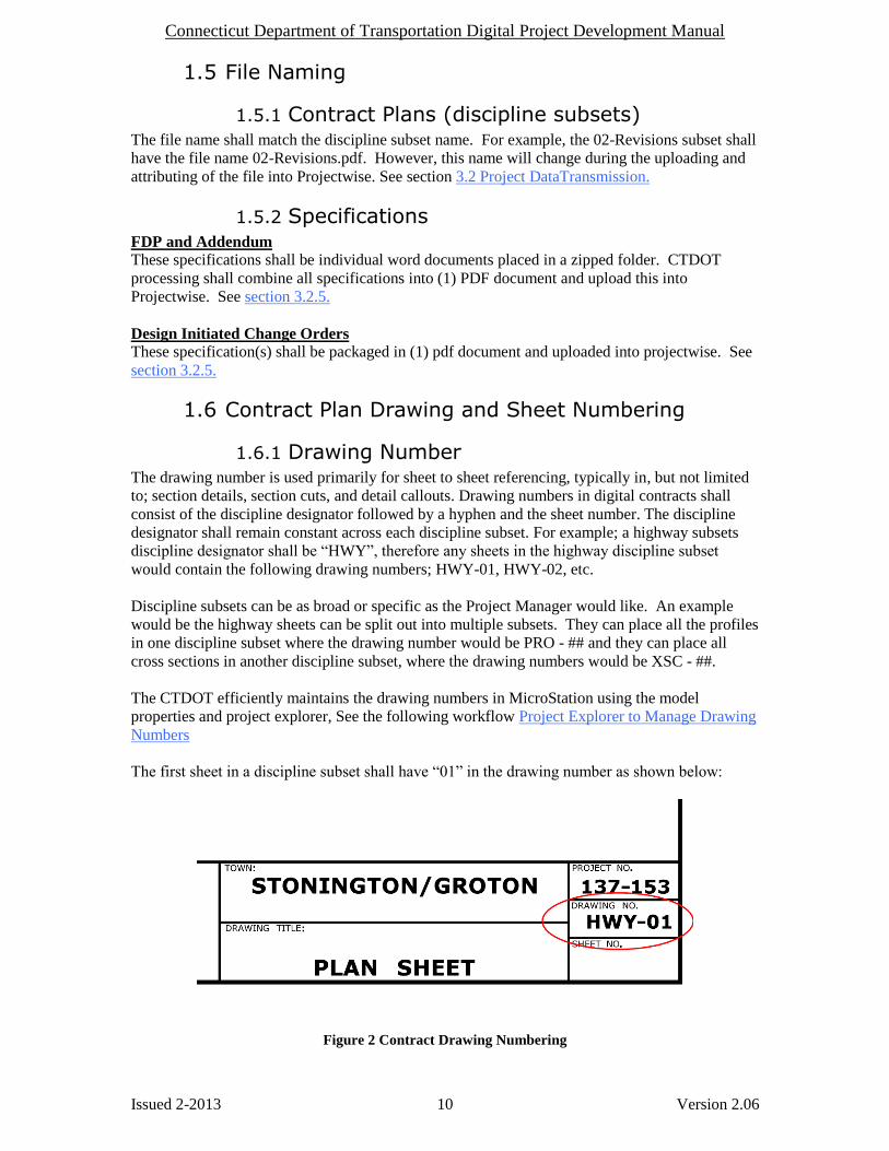
1.6.1 Drawing Number The drawing number is used primarily for sheet to sheet referencing, typically in, but not limited
to; section details, section cuts, and detail callouts. Drawing numbers in digital contracts shall
consist of the discipline designator followed by a hyphen and the sheet number. The discipline
designator shall remain constant across each discipline subset. For example; a highway subsets
discipline designator shall be “HWY”, therefore any sheets in the highway discipline subset
would contain the following drawing numbers; HWY-01, HWY-02, etc.
Discipline subsets can be as broad or specific as the Project Manager would like. An example
would be the highway sheets can be split out into multiple subsets. They can place all the profiles
in one discipline subset where the drawing number would be PRO - ## and they can place all
cross sections in another discipline subset, where the drawing numbers would be XSC - ##.
The CTDOT efficiently maintains the drawing numbers in MicroStation using the model
properties and project explorer, See the following workflow Project Explorer to Manage Drawing
Numbers
The first sheet in a discipline subset shall have “01” in the drawing number as shown below:
Figure 2 Contract Drawing Numbering

Connecticut Department of Transportation Digital Project Development Manual
Issued 2-2013 11 Version 2.06
1.6.2 Final Plan Sheet Numbers Sheet numbers are applied to the discipline subset after the contract plans are published to PDF.
Sheet numbers shall be managed and placed on the discipline subsets, using the header and footer
tool within Adobe Acrobat or Bluebeam. Sheet numbers shall be applied to all submissions of
contract plans.
The first sheet in every subset shall start out at 01. For example the first sheet in the 03-Bridge
subset shall be 03.01.
Figure 3 - Drawing and Sheet Numbering
The sheet number place holder shall be determined by the total estimated sheet count. For less
than 100 sheets two place holders is adequate. For greater than or equal to 100 sheets three place
holders are necessary. For subsets less than 10 sheets, two placeholders shall be used i.e. 01.01
thru 01.04 for a four sheet subset.
The sheet number must be placed correctly because it is used to correctly assemble the contract
plans into a properly ordered consolidated set.
Single Volume Projects:
The sheet number, for single volume projects shall be a concatenation of the discipline subset
number, a decimal point, and the sheet number. For example; the sheet numbers for subset “4”
would be as follows; less than 100 sheets 04.01, 04.02, 04.03, etc or Greater than 100 sheets
04.001, 04.002, 04.003 etc.
The Project Manager should determine the total number of subsets and give each discipline their
corresponding subset number, see section 1.11.
Multi Volume Projects:
For a multi volume project the sheet number shall be a concatenation of the volume number, a
decimal point, the discipline subset number, a decimal point, and finally the sheet number.
Example: Volume 2, Subset 5; 02.05.01, 02.05.02, 02.05.01.
Volume numbers shall be used on large projects. They are effective because the Project Manager
only has to deliver to the other engineers their perspective volume numbers, allowing them to
manage their subset numbers independently of the other discipline volumes and subset counts, see
section 1.12.
Subset numbers shall start at 01 for all volumes.

Connecticut Department of Transportation Digital Project Development Manual
Issued 2-2013 12 Version 2.06
1.6.2.1 ADOBE - Applying Sheet Numbers
The following workflow gives an example of placing sheet numbers on a single volume project
on the ‘03” subset that contains fewer than 100 sheets. The sheet numbers are added using the
Header and Footer tool in Adobe Acrobat.
1. From Adobe Acrobat select “Document/Header & Footer/Add”
2. Place the sheet numbers on all sheets, as shown below.
Figure 4 Sheet Numbering
Connecticut Department of Transportation Digital Project Development Manual
Issued 2-2013 13 Version 2.06
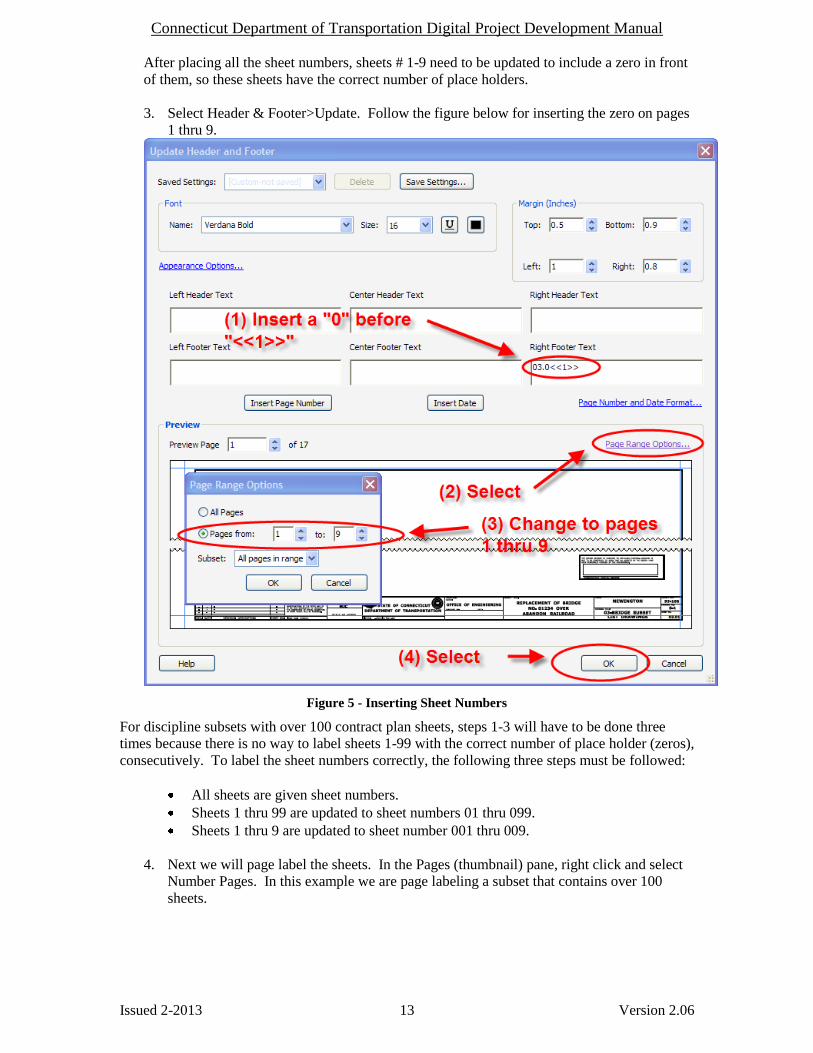
After placing all the sheet numbers, sheets # 1-9 need to be updated to include a zero in front
of them, so these sheets have the correct number of place holders.
3. Select Header & Footer>Update. Follow the figure below for inserting the zero on pages
1 thru 9.
Figure 5 - Inserting Sheet Numbers
For discipline subsets with over 100 contract plan sheets, steps 1-3 will have to be done three
times because there is no way to label sheets 1-99 with the correct number of place holder (zeros),
consecutively. To label the sheet numbers correctly, the following three steps must be followed:
All sheets are given sheet numbers.
Sheets 1 thru 99 are updated to sheet numbers 01 thru 099.
Sheets 1 thru 9 are updated to sheet number 001 thru 009.
4. Next we will page label the sheets. In the Pages (thumbnail) pane, right click and select
Number Pages. In this example we are page labeling a subset that contains over 100
sheets.
Connecticut Department of Transportation Digital Project Development Manual
Issued 2-2013 14 Version 2.06
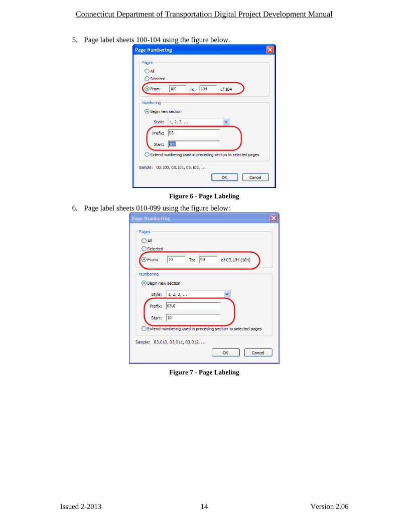
5. Page label sheets 100-104 using the figure below.
Figure 6 - Page Labeling
6. Page label sheets 010-099 using the figure below:
Figure 7 - Page Labeling

Connecticut Department of Transportation Digital Project Development Manual
Issued 2-2013 15 Version 2.06
7. Page label sheets 001-009 using the figure below:
Figure 8 - Page Labeling

Connecticut Department of Transportation Digital Project Development Manual
Issued 2-2013 16 Version 2.06
1.6.2.2 BLUEBEAM - Applying Sheet Numbers
To apply sheet numbers in Bluebeam follow the figures below:
1. First page labels must be applied to the discipline subset. Go to the thumbnail pane as
shown below, right click on a thumbnail and select Number Pages:
Figure 9 - Adding Page Labels
In this example there are less than 10 sheets in the subset so we can apply the page labels to all
the sheets at once. In the case where there are 10 or more sheets in the subset the following will
have to be done twice. This is done so the prefix shown below has the correct number of place
holders. If the subset has 99 sheets or less an example for the 04 prefix shall be “04.0” for sheets
1-9 and “04.” For sheet 10 through 99.
2. Select the correct style, insert correct prefix for the sheets being numbered, and apply to
the correct pages.
Figure 10- Page Labeling
Connecticut Department of Transportation Digital Project Development Manual
Issued 2-2013 17 Version 2.06
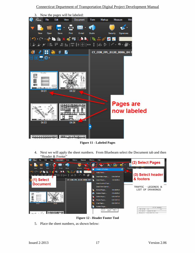
3. Now the pages will be labeled:
Figure 11 - Labeled Pages
4. Next we will apply the sheet numbers. From Bluebeam select the Document tab and then
“Header & Footer”
Figure 12 - Header Footer Tool
5. Place the sheet numbers, as shown below:

Connecticut Department of Transportation Digital Project Development Manual
Issued 2-2013 18 Version 2.06
Figure 13 - Insert Sheet Numbers
Connecticut Department of Transportation Digital Project Development Manual
Issued 2-2013 19 Version 2.06
1.6.3 Addendum and Design Initiated Change Order Sheet Numbers
Sheet numbers for an Addendum need to have “.A#” at the end and Change Orders need to have a
“.C#” at the end (see section 4) and Working drawings need to have a “.WD” at the end (see
section 6).
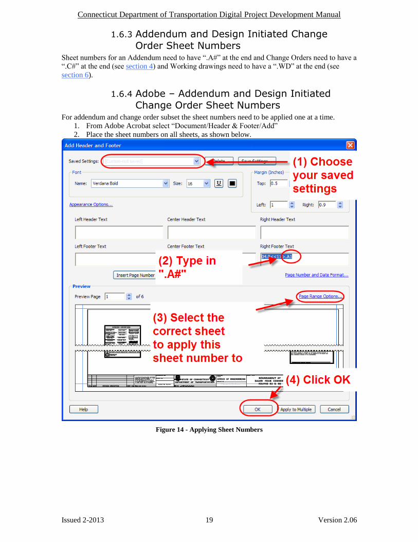
1.6.4 Adobe – Addendum and Design Initiated Change Order Sheet Numbers
For addendum and change order subset the sheet numbers need to be applied one at a time.
1. From Adobe Acrobat select “Document/Header & Footer/Add”
2. Place the sheet numbers on all sheets, as shown below.
Figure 14 - Applying Sheet Numbers
Connecticut Department of Transportation Digital Project Development Manual
Issued 2-2013 20 Version 2.06
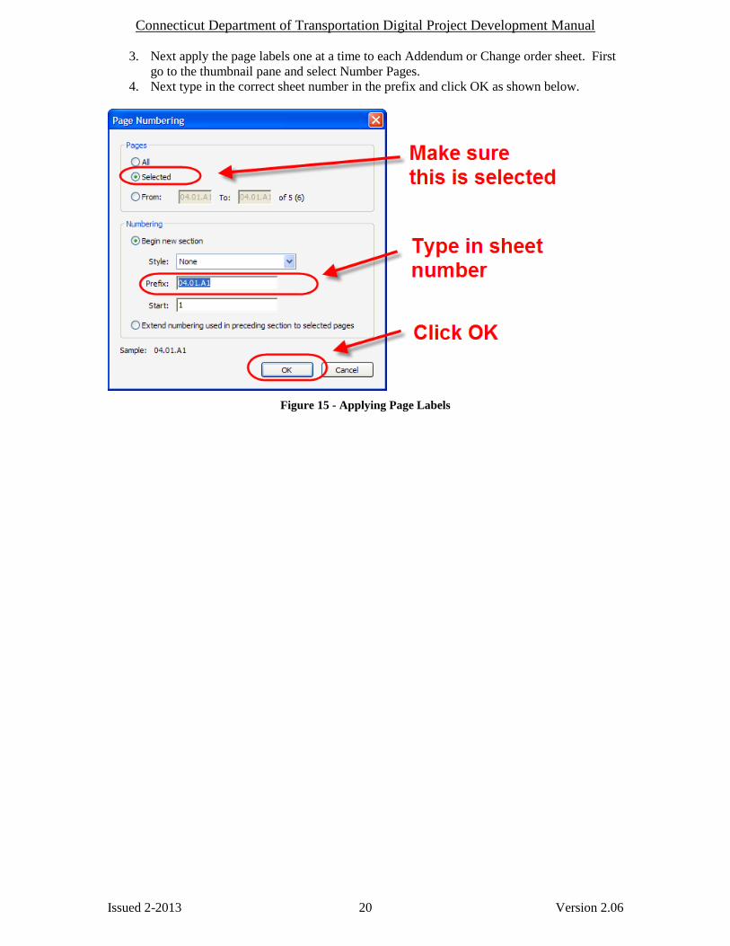
3. Next apply the page labels one at a time to each Addendum or Change order sheet. First
go to the thumbnail pane and select Number Pages.
4. Next type in the correct sheet number in the prefix and click OK as shown below.
Figure 15 - Applying Page Labels

Connecticut Department of Transportation Digital Project Development Manual
Issued 2-2013 21 Version 2.06
1.6.5 Bluebeam – Addendum and Design Initiated Change Order Sheet Numbers
1. First page labels must be applied to each sheet in the addendum or change order. This
can only be done on sheet at a time.
2. Go to the thumbnail pane as shown below, right click on a thumbnail and select Number
Pages:
Figure 16 - Adding Page Labels
3. Select None for a style, type in the sheet number of the addendum or change order sheet
for a prefix. An example of this would be addendum sheet 04.01.A1 shall be entered as a
prefix. Then select which sheet you are labeling. This has to be done for each sheet in
the addendum or change order separately. See below:
Figure 17 - Applying Addendum Page Labels
Connecticut Department of Transportation Digital Project Development Manual
Issued 2-2013 22 Version 2.06
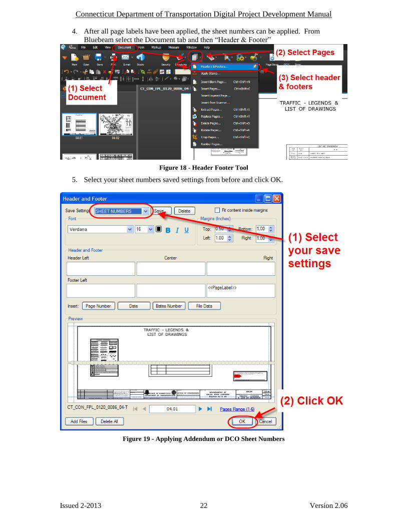
4. After all page labels have been applied, the sheet numbers can be applied. From
Bluebeam select the Document tab and then “Header & Footer”
Figure 18 - Header Footer Tool
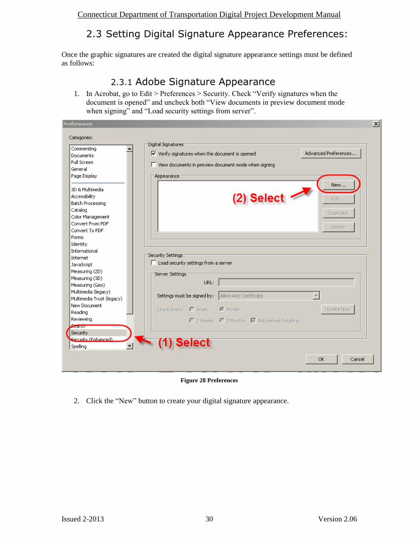
5. Select your sheet numbers saved settings from before and click OK.
Figure 19 - Applying Addendum or DCO Sheet Numbers

Connecticut Department of Transportation Digital Project Development Manual
Issued 2-2013 23 Version 2.06
1.7 CTDOT For Information Only Sheets
Plans provided For Information Only (FIO) shall be submitted digitally, in individual subsets
based on the entity providing the information, Amtrak, CL & P, AT&T, Designer etc. These
subsets do not require a digital signature, but each sheet in the subset shall be labeled; “For
Information Only”. These sheets shall be placed on a border and numbered in accordance with
section 1.6.2.
The subset numbers shall be selected by the Project Manager so that the FIO subsets are last. See
Section 3.2 for uploading and attributing FIO Plans. See Section 1.11 & 1.12 for more examples
of discipline subsets. Information only sheets may be scanned, but must conform to the following
specifications; Minimum Size 22”x34”, Minimum dpi = 300.
1.8 CTDOT Standard Sheets Standard sheets shall also be delivered digitally. The workflow
Assembling_CTDOT_Standard_Sheets.pdf explains how to obtain, create standard sheet subsets,
and insert them into a digital project. For submission of CTDOT Standard Sheets, see section
3.2.
1.9 Contract Plan Sheet Publishing CTDOT currently uses MicroStation V8i Print Plot and Print Organizer to publish contract plans
to a PDF format.
The workflow Publishing_MicroStation_Content_to _PDF_Format.pdf shows the fundamentals
of publishing contract plans to PDF from MicroStation.

Connecticut Department of Transportation Digital Project Development Manual
Issued 2-2013 24 Version 2.06
1.10 Example: Typ. Single Volume Digital Contract Single volume digital contracts are used when each discipline or consulting firm designing the
project is responsible for 3 subsets or less. The following is an example of a single volume
project. Note: The first and second subsets shall always be 01-General and 02-Revisions. The
03 subset does not always need to be 03-Highways, the 04 does not always need to be 04-
Structure, etc. The FIO subsets shall be placed at the end of a project right before the STD
subsets.
Label
(Discipline Subset)
File contents
(but not limited to)
01-General
Title Sheet
Detail Estimate Sheet
Etc
02-Revisions
Index of Revisions Sheets
03-Highways**
Index of Plans
Survey Data
Alignments
ROW
Typ Sections
Misc Details
Intersect Grading
Boring Logs
Highway Plans
Breakout Drainage
Highway Profile
Highway X-
Sections
Landscape Plan
Wetland Mitigation
04-Structure
Index of Drawings
All Structure Sheets
Note: Multiple subsets may required for multiple
Sites
Ex: 04_Structure_Br.No.1266
05-Traffic
Index of Drawings
Signing
Pavement Markings
MPT
Traffic Signal Plans
Etc.
06-Environmental Index of Drawings
All Environmental Compliance Sheets required
07-”Utiltiy” Utility Design plans. For example 07_AT & T, 07_CL & P, 07_MDC, etc.
08-CL&P FIO*** CL & P For Information Only plans
09-AT&T FIO*** AT & T For Information Only plans
CTDOT Highway STD * CTDOT Highway Design Standard Index and Sheets required
CTDOT Traffic STD * CTDOT Traffic Engineering Standard Index and Sheets required
Figure 20 Typical Highway Project Discipline Subset Contents
* For using CTDOT Standard Sheets see X1.5X XCTDOT Standard Sheet Assembly
** If a discipline has to be broken up into more than one subset See Section 1.11 for splitting up
the discipline subsets.
*** For Information only discipline subset shall be submitted as individual pdf files based on the
entity providing the information only.

Connecticut Department of Transportation Digital Project Development Manual
Issued 2-2013 25 Version 2.06
1.11 Example: Multiple Volume Digital Contract Multiple volumes are used if the project has 1 or more of the following characteristics:
1. The majority of the discipline/firm designers are responsible for more than 3 subsets
each. This allows the individual designers to number their subsets independently of the
other disciplines.
2. There are multiple sites on the project. Splitting these sites up into volumes will provide
better organization of the project.
The larger the project is, typically the more subsets will be required and their labels will be more
specific. The Project Manager will need to organize the discipline volumes. The subsets shall
be split up by volume and each volume shall be controlled by its assigned designer. For example,
all the subsets designed by the highway designer shall be in the same volume (02) and each
subset shall have a unique subset number. For example, see subset 02.02_Alignments and
02.03_Plans as shown below.
Label
(Discipline Subset)
File contents
(but not limited to)
Designer/
Firm
01.01-General Title Sheet, Detail Estimate Sheet Etc Lead
01.02-Revisions Index of Revision Sheets Lead
01.03-Wtlnd Re-establish Wetland Reestablishment plans Designer 1
01.04-Stg Acc. Staging and Access Plans Designer 1
02.01-Typ Sections Typical Sections Designer 2
02.02-Alignments Alignment Geometry Designer 2
02.03-Plan Plans Designer 2
02.04-Profiles Profiles Designer 2
02.05-ROW Brk Right of Way Breakout Designer 2
02.06-Drain Drainage Plans Designer 2
03.01-Retaining Wall 1 Retaining wall details Designer 3
03.02-Retaining Wall 2 Retaining wall details Designer 3
03.03-Bridge 00456 Bridge_456 Designer 3
03.04-Bridge 01983 Bridge_1983 Designer 3
03.05-Bridge 01984 Bridge_1984 Designer 3
04.01-Stage 1 Stage Construction Details 1 Designer 4
04.02-Stage 2 Stage Construction Details 2 Designer 4
04.03-Stage 3 Stage Construction Details 3 Designer 4
05.01-SPM Signing and Pavement Marking Site 1 Designer 5
05.02-SPM Signing and Pavement Marking Site 2 Designer 5
05.03-SPM Signing and Pavement Marking Site 3 Designer 5
06.01-IMS IMS Plans and Details Site1,2,3 Designer 6
07.01-Env 1 Environmental Details Site 1 Designer 7
07.02-Env 2 Environmental Details Site 2 Designer 7
07.03-Env 3 Environmental Details Site 3 Designer 7
08.01-”Utiltiy” Utility Design plans. For example 07_AT & T, 07_CL & P, 07_MDC, etc.
Designer 8
09.01-CL&P FIO CL & P For Information Only plans Designer 8
09.02-AT&T FIO AT & T For Information Only plans Designer 8
CTDOT Highway STD * CTDOT Highway Design Standard Index and Sheets required
Designer 1
CTDOT Traffic STD * CTDOT Traffic Engineering Standard Index and Sheets required
Designer 5
Figure 21 – Multiple Design Firms CTDOT Project Subsets

Connecticut Department of Transportation Digital Project Development Manual
Issued 2-2013 26 Version 2.06
Label
(Discipline Subset)
File contents
(but not limited to)
Designer/
Firm
01.01_General Title Sheet, Detail Estimate Sheet Etc Lead
01.02_Revisions Index of Revision Sheets Lead
01.03_Wtlnd_Re-establish Wetland Reestablishment plans Designer 1
01.04_Stg_Acc. Staging and Access Plans Designer 1
02.01_Typ_Sections Typical Sections Designer 2
02.02_Alignments Alignment Geometry Designer 2
02.03_Plan Plans Designer 2
02.04_Profiles Profiles Designer 2
02.05_ROW_Brk Right of Way Breakout Designer 2
02.06_Drain Drainage Plans Designer 2
03.01_Branford_Station Branford Station Designer 2
03.02_Retaining_wall_2 Retaining wall details Designer 2
03.03_Architectural Architectural Details Designer 2
03.03_Mechanical Mechanical Details Designer 2
03.03_Electrical Electrical Details Designer 2
04.01_Guilford Station Guilford Station Designer 2
04.02_Architectural Architectural Details Designer 2
04.03_Mechanical Mechanical Details Designer 2
05.01_”Utiltiy” Utility Design plans. For example 07_AT & T, 07_CL & P, 07_MDC, etc.
Designer3
06.01_CL&P_FIO CL & P For Information Only plans Designer 1
06.02_AT&T_FIO AT & T For Information Only plans Designer 1
CTDOT_Highway_STD * CTDOT Highway Design Standard Index and Sheets required
Designer 1
CTDOT_Traffic_STD * CTDOT Traffic Engineering Standard Index and Sheets required
Designer 2
Figure 22 - Multiple Site CTDOT Facilities Project Subsets

Connecticut Department of Transportation Digital Project Development Manual
Issued 2-2013 27 Version 2.06
Digital Signatures for Contract Section 2
Plans
This manual refers to digital signatures in two ways: certifying signatures, and signing signatures.
The Engineer of Record will always digitally sign using a visible certifying signature. If multiple
signatures are required per document, the sub-engineers shall always digitally sign using a visible
signing signature after the primary engineer has applied his certifying signature. Certifying
signatures allow controlled changes, to the now certified document. These controlled changes
include; allowing PDF digital comments, and the application of additional signatures. Signing
signatures should always be accompanied by a note listing the sheets the signer is responsible for
within a subset.
In order to digitally secure a PDF document the signer(s) applies a digital signature(s) to only the
first sheet of each discipline subset(s), regardless of the number of pages the subset contains. This
single digital signature secures the entire document.
A graphic image of the signer’s signature must be created, and shall be used for the following two
purposes. First, it shall be attached to the digital signature and displayed when the digital
signature is applied. Second, it shall be placed as a watermark on all sheets a particular engineer
of record is responsible for, and is digitally signing. The watermark shall be placed on all sheets
in a working drawing submittal.
A digital ID must be purchased in order to apply a digital signature. Digital ID’s must meet the
specifications of Adobe’s Certified Document Services (CDS). The necessary hardware and
software needed to apply the required digital signatures may be purchased from the vendor list
provided at the following website: HUhttp://www.adobe.com/security/partners_cds.html UH, additional
information on Adobe’s CDS is also available at this website.
2.1 Graphic Image of Signature
The following figure displays an example of both a state designer and a consultant designer’s
digital signatures, and their accompanying graphic image(s) of their signature(s).
The consultant engineer’s graphic image must contain his companies name and address; his
signature, his Professional Engineers stamp, or his Professional Architecture Stamp. The state
employee’s graphic image must contain only his signature. See Below.
Figure 23 - Graphic Image of Signature
Although discipline subsets requires only one digital signature applied to the first page to
complete the certification process and ensure security; the CTDOT also requires that all
subsequent pages be watermarked with a copy of the engineer of records graphic signature before
1st page of Subset

Connecticut Department of Transportation Digital Project Development Manual
Issued 2-2013 28 Version 2.06
they are digitally signed. Watermarks containing these signatures are applied using Adobe
Acrobat or Bluebeam and are always placed in the border as shown. This is to prove validation of
a digital document if printed.
Figure 24 - Watermark
2.2 Creating Graphic Image of Signature:
2.2.1 CTDOT Staff: The graphic signature of CTDOT employees shall consist of only their signature; P.E. stamps are
not required.
The following CTDOT employees need to create graphic images of their signatures: Principal
Engineer (required to digitally sign plans), Manager of State Design, and the Engineering
Administrator. CTDOT graphic signatures shall be created as follows:
1. Signer must sign a blank piece of paper.
2. Scan this signature.
3. Crop the image so that the image is approximately 300 pixels wide by 100 pixels high.
4. Save the images, in PDF if using Adobe or in Tiff if using Bluebeam, to an area on your
PC.
Figure 25 (Example of CTDOT Graphic Image of Signature – Used with Digital Signature and as a Watermark)
Watermark of State Design Graphic Signature
Watermark of Consultant Designers
Graphic Signature

Connecticut Department of Transportation Digital Project Development Manual
Issued 2-2013 29 Version 2.06
2.2.2 For Consultant Staff:
Consultant Engineers shall create two different graphic signature images: one that shall
accompany their digital signatures and a different one that shall be placed as a watermark on all
the sheets the designer is signing for.
This section shows an example of a Professional Engineer preparing their graphic image of their
signature; Architect’s shall follow this section when they are preparing their digital signature.
The graphic signature that shall accompany the digital signature needs only to include the
designer’s signature and P.E. Stamp. , and shall be created as follows:
1. Stamp and Sign a blank piece of paper.
2. Scan this signature.
3. Crop the image to approximately 250 pixels wide by 250 pixels high.
4. Save the image, in PDF if using Adobe / in Tiff if using Bluebeam, to an area on your PC
or server, where you can easily access it for later use in the signature set-up procedure.
Figure 26 ((Example of Consultant Engineer Graphic image of Signature – Applied to 1st page only with digital signature)
In addition to the designer’s signature and P.E. Stamp, the graphic signature that is placed as a
watermark shall also include the designer’s company name and address, and shall be created as
follows:
1. On blank paper – Print company name and address.
2. Place P.E. stamp next to company name and address.
3. Sign P.E. Stamp.
4. Scan the image created in steps 1 thru 3 above.
5. Crop the image to approximately 500 pixels wide by 250 pixels high.
6. Save the image, in PDF if using Adobe / in Tiff if using Bluebeam, to an area on your PC
or server, where you can easily access it for later use in the watermarking procedure.
Figure 27 (Example of Consultant Engineer Graphic image of Signature – applied to all pages as a watermark)
Once the graphic images have been properly created and saved, the digital signature appearance
preferences must be set as follows:
Connecticut Department of Transportation Digital Project Development Manual
Issued 2-2013 30 Version 2.06
2.3 Setting Digital Signature Appearance Preferences:
Once the graphic signatures are created the digital signature appearance settings must be defined
as follows:
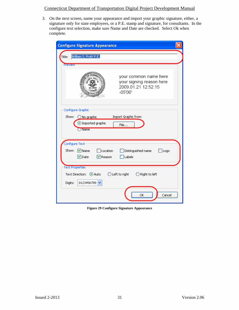
2.3.1 Adobe Signature Appearance 1. In Acrobat, go to Edit > Preferences > Security. Check “Verify signatures when the
document is opened” and uncheck both “View documents in preview document mode
when signing” and “Load security settings from server”.
Figure 28 Preferences
2. Click the “New” button to create your digital signature appearance.
Connecticut Department of Transportation Digital Project Development Manual
Issued 2-2013 31 Version 2.06
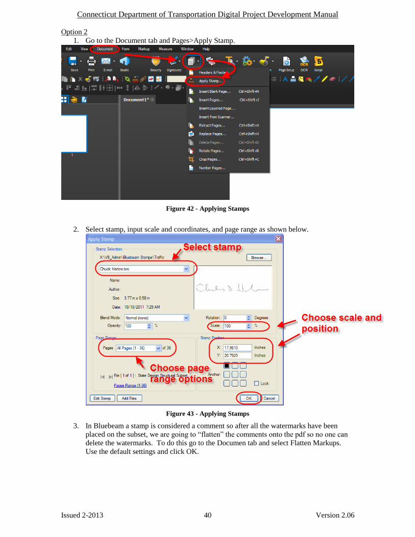
3. On the next screen, name your appearance and import your graphic signature, either, a
signature only for state employees, or a P.E. stamp and signature, for consultants. In the
configure text selection, make sure Name and Date are checked. Select Ok when
complete.
Figure 29 Configure Signature Appearance

Connecticut Department of Transportation Digital Project Development Manual
Issued 2-2013 32 Version 2.06
4. In the Preferences Dialog, see figure 17, go to Advanced Preferences. Select options in
each tab in the following figures:
Figure 30 Advanced Preferences

Connecticut Department of Transportation Digital Project Development Manual
Issued 2-2013 33 Version 2.06
Figure 31 Advanced Preferences
Figure 32 - Windows Integration

Connecticut Department of Transportation Digital Project Development Manual
Issued 2-2013 34 Version 2.06
2.3.2 Bluebeam Digital Appearance 1. Make sure your CDS USB token is inserted into the computer then in Bluebeam go to the
Document tab and select Signatures>Digital ID’s:
Figure 33 - Digital Appearance
2. Next click on your ID and click Manage Appearances:
Figure 34 - Manage Appearances

Connecticut Department of Transportation Digital Project Development Manual
Issued 2-2013 35 Version 2.06
3. Next follow the figure below:
Figure 35 - Setting the Digital Appearance
4. Now the digital appearance will be saved and can be used to digitally sign.

Connecticut Department of Transportation Digital Project Development Manual
Issued 2-2013 36 Version 2.06
2.4 Watermarking Plans with Graphic Image of Signature
The Engineer of Record (Principal Engineers for State Design), for each discipline, shall place a
copy of their graphic signature as a watermark on each page of each discipline subset, or working
drawing submittal that they are responsible for.
2.4.1 Adobe – Watermarking Plans with Graphic Image of Signature
1. From Adobe Acrobat select Document> Watermark>Add.
2. In the Add Watermark dialog box browse to your graphic signature
(X:\V8_Admin\Digital_Signatures_For_Watermarks)
3. Adjust Scale Relative to page as shown below.
4. Adjust position as shown below.
5. Shall be placed on all sheets, except on the title sheet in the 01-General subset. This
sheet does not need a watermark. See figure below (#5) for selecting page range options.
6. Save settings when complete for future use.
2.4.1.1 CTDOT Designed Plans
Figure 36 Add CTDOT Watermark Dialog

Connecticut Department of Transportation Digital Project Development Manual
Issued 2-2013 37 Version 2.06
Figure 37 CTDOT Signature Watermark
2.4.1.2 Consultant Designed Contract Plans
Figure 38 Consultant PE Stamp, Company and Address - Watermark Dialog

Connecticut Department of Transportation Digital Project Development Manual
Issued 2-2013 38 Version 2.06
Figure 39 Consultant Completed Watermark
2.4.2 Bluebeam - Watermarking Plans with Graphic Image of Signature (CTDOT and Consultant Designed)
The engineer of record (Principal Engineers for State Design), for each discipline, shall place a
copy of their graphic signature as a watermark on each page of each discipline subset, or working
drawing submittal that they are responsible for. There are two ways to apply watermarks using
Bluebeam, see below for options 1 and 2.
Watermarking Workflow:
Option 1
1. The watermark in Bluebeam is placed using the stamp function. First go to the Markup
tab and select Stamp and then choose your stamp. If your stamp is not in the list follow
section Section 7.3. If your stamp is in the list go to step 2.
2. Next Place the stamp in the border on the first sheet
Figure 40 - Placing Watermark

Connecticut Department of Transportation Digital Project Development Manual
Issued 2-2013 39 Version 2.06
3. Next right click on the stamp and select “Apply to all pages”
Figure 41 - Placing Watermark on All Pages
If more than one group has to watermark this subset, browse to the pages the other group is
responsible for and delete the watermark. Then they can come in a place their watermark on
these sheets.
4. In Bluebeam a stamp is considered a comment so after all the watermarks have been
placed on the subset, we are going to “flatten” the comments onto the pdf so no one can
delete the watermarks. To do this go to Document>Flatten Markups. Use the default
settings and click OK.
Connecticut Department of Transportation Digital Project Development Manual
Issued 2-2013 40 Version 2.06
Option 2
1. Go to the Document tab and Pages>Apply Stamp.
Figure 42 - Applying Stamps
2. Select stamp, input scale and coordinates, and page range as shown below.
Figure 43 - Applying Stamps
3. In Bluebeam a stamp is considered a comment so after all the watermarks have been
placed on the subset, we are going to “flatten” the comments onto the pdf so no one can
delete the watermarks. To do this go to the Documen tab and select Flatten Markups.
Use the default settings and click OK.

Connecticut Department of Transportation Digital Project Development Manual
Issued 2-2013 41 Version 2.06
2.5 Digital Signature Fields
Digital signature fields are form fields created using Adobe Acrobat or Bluebeam, and are used to
house the digital signatures. Digital Signature form fields shall be superimposed onto form field
place holders. The form field place holders are cells that are placed in the MicroStation file on the
title sheet and the subset cover sheets and on any Addendum or Change Order Subset. The figure
below shows a CTDOT designed project with the form field place holders (circled) on the title
sheet and the discipline subset cover sheet.
Figure 44 - Digital Signature Fields
The figure below shows a consultant designed project’s title sheet and discipline subset cover
sheet with their form field place holders.
Place holders determine the location and size of the digital signature form field.
Form field place holding cell library: CT_Digital_Sigs.zip
The digital signature place holder and form fields shall be created on the first page of each
discipline subset for each required digital signature.
All signature form fields need to be created for both certifying and signing signatures before any
digital signatures is applied to the document.

Connecticut Department of Transportation Digital Project Development Manual
Issued 2-2013 42 Version 2.06
2.5.1 Adobe - Creating Digital Signature Form Fields
The following work flow explains how to add signature form fields to a PDF document.
1. In Acrobat select forms>Add or Edit Fields
2. When this dialog box appears - Select No.
Figure 46 - Auto Detect Fields
3. Select Add New Field>Digital Signature.
Figure 45 Manually Placed Digital Signature Field

Connecticut Department of Transportation Digital Project Development Manual
Issued 2-2013 43 Version 2.06
Figure 47 - Placing Digital Signature Field
Place the digital signature form field in top left corner of place holder and adjust bottom right
corner using handles.
Figure 48 - Placing Digital Signature Field
Figure 49 Signature Field placed on Inside Box – Consultant Signature field
Next, click the Close Form Editing button located in the upper right hand corner of view.
Figure 50 - Close For Editing

Connecticut Department of Transportation Digital Project Development Manual
Issued 2-2013 44 Version 2.06
2.5.2 Bluebeam - Creating Digital Signature Form Fields
The following example shows how to place the (3) digital signature form fields on the 01-General
title sheet of a CTDOT designed project. For a discipline subset or a consultant designed 01-
General title sheet, only one digital signature form field needs to be placed.
1. Go to the Document tab and select Signatures>Add Signature Field.
Figure 51 - Adding Signature Fields
2. Next place three signature fields in the appropriate location and hit save as shown below:
Figure 52 - Placing Signature Fields
Connecticut Department of Transportation Digital Project Development Manual
Issued 2-2013 45 Version 2.06
2.6 Applying Digital Signatures This section describes how to apply digital signatures. Subsets 01-General and 02-Revisions and
the Highway and Traffic Standard drawing subsets have unique requirements as described in the
following sections.
CTDOT projects shall have their subsets digitally signed after they have been uploaded into
projectwise because the Principal Engineer will be looking in projectwise to digitally sign
documents.
Discipline subsets designed by a single engineer shall be digitally signed, by the engineer of
record, using a single visible certifying signature, applied to the signature form field located on
the first page of each subset.
Discipline subsets designed by multiple engineers shall first be digitally signed by the Engineer of
Record who is responsible for the most sheets in the subsets. This engineer will apply a visible
certifying signature in the top most form field. The next Engineer of Record shall apply their
signing signatures in the subsequent form fields. This Engineer shall also include a reason, when
applying their digital signatures, listing the pages they are responsible for.
Digital signatures must be applied to digital form fields, previously created. See Section 2.5
2.6.1 Applying Digital Signatures to 01_General Subset (FDP and Addendum Subsets)
CTDOT DESIGNED PROJECTS:
The following procedure applies to both the 01_General subset at FDP and any 01_General_A#
subset.
The project title sheet of the 01_General subset shall first be digitally signed by the lead
discipline’s Principal Engineer, using a certifying signature. The Principal Engineer should
make sure that all three digital signature form fields (blue boxes in the signature block) areplaced
before signing, as these forms cannot be added after the document is digitally certified. After
processing has approved the 01_general subset for Advertising, the Manager, and the
Transportation Engineering Administrator shall digitally sign the same sheet directly below the
principal’s signature, using a signing signature while the plans are in the Manager and
Engineer Admin. Sign state.
Processing shall notify the lead designer when the 01-General subset is placed in the Manager
and Engineer Admin. Sign state. The lead designer shall then coordinate the digital signing by
the Manager and Engineering Administrator of the 01_General subset. When both signatures are
applied to the plans, the lead designer shall then notify processing that the 01-General subset has
been signed.
See Section 2.6.7 Applying Digital Signature Workflows
Note: When digitally signing the 01_General subset all signers shall leave the reason code blank.
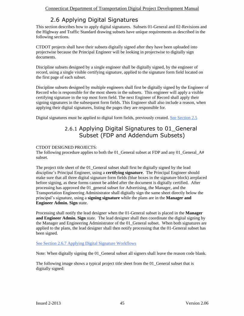
The following image shows a typical project title sheet from the 01_General subset that is
digitally signed:

Connecticut Department of Transportation Digital Project Development Manual
Issued 2-2013 46 Version 2.06
Figure 53 - Title Sheet Digital Signatures
Figure 54 Example: CTDOT 01_General.pdf, Project Title Sheet Digital Signatures
CONSULTANT DESIGNED PROJECTS:
The project title sheet of the 01_General subset shall be digitally signed by the lead consultant,
using a certifying signature.
See Section 2.6.7 Applying Digital Signature Workflows
When more than one consultant works on a CTDOT digital project the project manager (prime
consultant) shall apply a visible certifying signature to the first page of the 01_General subset.
By applying this signature the prime consultant is accepting responsibility for the entire set of
digital contract plans. However the individual subsets shall be signed by the corresponding firms.
Note: When applying certifying or signing signatures leave the reason code blank.

Connecticut Department of Transportation Digital Project Development Manual
Issued 2-2013 47 Version 2.06
2.6.2 Applying a Digital Signatures to 02_Revisions Subset
This section applies to both CTDOT designed projects and Consultant designed projects. The
figures contained in this section show a consultant signature, but the workflows are the same.
This subset does not need to be signed at FDP. This subset must be signed when the sheet is
filled out for an Addendum or design initiated change order, whichever comes first.
The first index of revision sheet(s) located in the 02_Revisions subset shall be digitally
signed by the lead designer, using a certifying signature.
1. The lead designer shall apply a certifying signature as described in section 2.6.7
Applying Digital Signature Workflows with the following EXCEPTION; the option
“No Changes Allowed” must be selected to eliminate unauthorized changes after
certifying the document. See the figure below:
Figure 55 Certifying Dialog Box for 02_Revisions.pdf

Connecticut Department of Transportation Digital Project Development Manual
Issued 2-2013 48 Version 2.06
2.6.3 All Other Discipline Subsets - Single Signature
This section applies to both CTDOT designed projects and Consultant designed projects. The
figures contained in this section show a consultant signature, but the workflow is the same.
Each discipline subset shall be digitally signed with a visible certifying signature, by ONLY the
responsible design engineer. As shown below.
See section 2.6.7 Applying Digital Signature Workflows
Figure 56 CTDOT Certified Plan Subset
2.6.4 Standard Drawing Subsets – Single Signature This section applies to both CTDOT designed projects and Consultant designed projects. The
figures contained in this section show a consultant signature, but the workflow is the same.
Only the standard drawing subset index sheets, Highways and Traffic Standard Drawings, need to
be digitally signed with a visible signing signature, by ONLY the responsible design engineer.
See section 2.6.7 Applying Digital Signature Workflows
2.6.5 All Other Discipline Subsets – Multi-Signatures
This section applies to both CTDOT designed projects and Consultant designed projects. The
figures contained in this section show a consultant signature, but the workflow is the same for
CTDOT designed projects.
Multiple signatures per a single subset are required where two or more disciplines/firms are
responsible for one subset.
The lead designer that is responsible for most of the pages within a discipline subset shall
digitally sign the subset using a certifying signature, and leave the reason code blank. See
Section 2.6.7 Applying Digital Signature Workflows
Once certified by the subset lead, the remaining designers(s) shall digitally sign the same subset
using a signing signature, and complete the reason code with a note stating which pages,
contained in this subset, that they are responsible for. See table 2-1 below:
See Section 2.6.7 Applying Digital Signature Workflows
Connecticut Department of Transportation Digital Project Development Manual
Issued 2-2013 49 Version 2.06
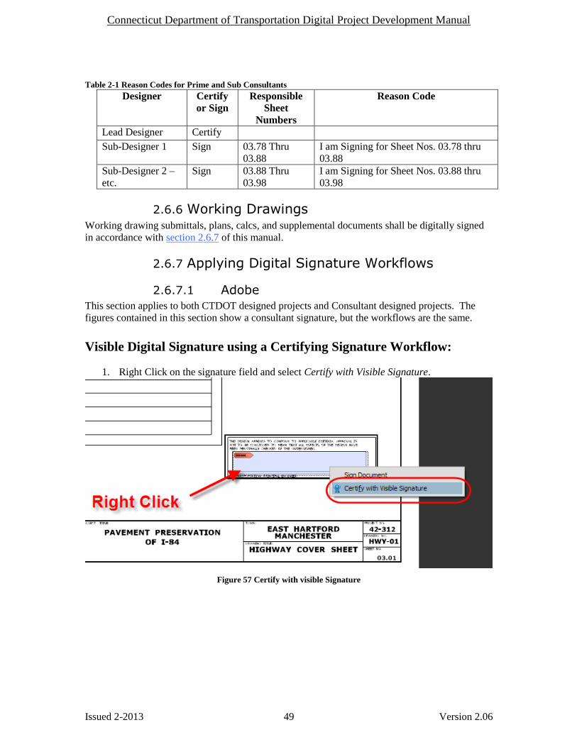
Table 2-1 Reason Codes for Prime and Sub Consultants
Designer Certify
or Sign
Responsible
Sheet
Numbers
Reason Code
Lead Designer Certify
Sub-Designer 1 Sign 03.78 Thru
03.88
I am Signing for Sheet Nos. 03.78 thru
03.88
Sub-Designer 2 –
etc.
Sign 03.88 Thru
03.98
I am Signing for Sheet Nos. 03.88 thru
03.98
2.6.6 Working Drawings Working drawing submittals, plans, calcs, and supplemental documents shall be digitally signed
in accordance with section 2.6.7 of this manual.
2.6.7 Applying Digital Signature Workflows
2.6.7.1 Adobe This section applies to both CTDOT designed projects and Consultant designed projects. The
figures contained in this section show a consultant signature, but the workflows are the same.
Visible Digital Signature using a Certifying Signature Workflow:
1. Right Click on the signature field and select Certify with Visible Signature.
Figure 57 Certify with visible Signature

Connecticut Department of Transportation Digital Project Development Manual
Issued 2-2013 50 Version 2.06
2. Select appearance and permitted actions as shown below:
Figure 58 Consultant Designed Certify with Visible Signature
3. Next it will ask you to save the document. Make sure to overwrite the existing document.
4. Enter password and click OK. The document will now be digitally signed.
Figure 59 Digital Signature Pass-phrase

Connecticut Department of Transportation Digital Project Development Manual
Issued 2-2013 51 Version 2.06
5. The document is certified correctly when there is a blue banner displayed on the top of
the sheet and in the signature properties it must say, “Only commenting, form fill-ins, and
signing and page adding actions are allowed.”
Figure 60 - Certified Correctly

Connecticut Department of Transportation Digital Project Development Manual
Issued 2-2013 52 Version 2.06
Visible Digital Signature using a Signing Signature Workflow: 1. Right Click on the signature field and select Sign Document.
Figure 61 Signing a Document
2. Select appearance and type in a reason following section 2.6.5.
Figure 62 Signing with Reason Code
3. Next it will ask you to save the document. Make sure to overwrite the existing document.
4. Enter password and click OK. The document will now be digitally signed.

Connecticut Department of Transportation Digital Project Development Manual
Issued 2-2013 53 Version 2.06
2.6.7.2 Bluebeam This section applies to both CTDOT designed projects and Consultant designed projects. The
figures contained in this section show a CTDOT signature, but the workflows are the same. The
Consultant designer will only have (1) signature.
Visible Digital Signature using a Certifying Signature Workflow: 1. Left click on the signature field and then update the settings as shown below:
Figure 63 - Certifying Signature Bluebeam
2. Next click “Save To” in Projectwise and select overwrite existing file:
3. Then check the document back into Projectwise.

Connecticut Department of Transportation Digital Project Development Manual
Issued 2-2013 54 Version 2.06
Visible Digital Signature using a Signing Signature Workflow: Once the prime engineer applies his certifying signature the additional signing signatures can be
applied by the sub-consultants as follows:
1. Left click on the signature field and then update the settings as shown below:
Figure 64 - Signing Signaure Bluebeam
2. Next click “Save To” in Projectwise and select overwrite existing file:
3. Then check the document back into projectwise.

Connecticut Department of Transportation Digital Project Development Manual
Issued 2-2013 55 Version 2.06
Submitting Documents to CTDOT Section 3
Projectwise
DIGITAL CONTRACT PLANS:
The CTDOT will consider all digital contract plans submitted for its use “official” contract
documents; the engineer of record shall not alter these documents unless explicitly asked to by
the CTDOT, and shall only alter what was requested. Consultant engineers submitting changes
that were not requested or submitting requested changes outside the processes in this manual may
be held liable for damages.
Check the following for completeness prior to submitting digital contract plans to the CTDOT.
When submitting preliminary plans only step 1 needs to be performed. All steps shall be
completed in accordance with this manual.
1. Project Manager should obtain the number of discipline subsets and notify each
discipline of their subset number for sheet numbering. FIO subsets shall be last.
2. All pages of the discipline subsets contain a footer displaying the sheet number.
3. All pages of the discipline subsets display a graphic signature of the engineer of
record (watermark).
4. The first sheet of each discipline subset shall be digitally signed by the engineer(s) of
record, and shall contain a list of drawings contained in that subset. In addition, the
first page of the 01_General subset must contain a list of subsets contained in the
project.
5. All sheets contained in any FIO subsets must be labeled, “For Information Only”
DIGITAL CONTRACT SPECIFICATIONS:
The Designer shall submit individual word documents for each specification into Projectwise, see
section 3.2.7. Specifications shall be prepared in accordance with the Departments policies and
procedures for Contract Development. CTDOT Processing shall combine all specifications into
(1) PDF document for the contract.
DIGITAL SUPPLEMENTAL CONTRACT DOCUMENTS:
Supplemental contract documents shall include but not limited to the list below:
Proposal Estimate, with signed checklist.
Federal Estimate
Calendar Day Estimate
Final Design Report
Categorical Exclusion
Design Approval Letter
Environmental Permits
DBE/SBE Approval with percentage
Commitment list
Agreements
Proprietary Item Approval
Stand alone Transportation Management Plan Document, taken from the final design
report
These documents shall be submitted to CTDOT in PDF format, except the proposal estimate, this
shall be in an “.est” format. If these documents do not need to be digitally signed, they may be
signed and scanned into PDF, however the minimum page size shall be 8.5” x 11” and the
minimum resolution shall be 200 dpi.
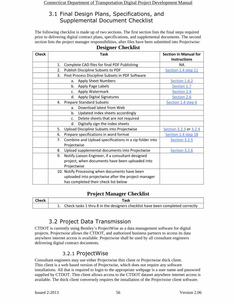
Connecticut Department of Transportation Digital Project Development Manual
Issued 2-2013 56 Version 2.06
3.1 Final Design Plans, Specifications, and Supplemental Document Checklist
The following checklist is made up of two sections. The first section lists the final steps required
prior to delivering digital contract plans, specifications, and supplemental documents. The second
section lists the project manager responsibilities, after files have been submitted into Projectwise:
Designer Checklist
Check Task Section in Manual for Instructions
1. Complete CAD files for final PDF Publishing NA
2. Publish Discipline Subsets to PDF Section 1.4 step 11
3. Post Process Discipline Subsets in PDF Software
a. Apply Sheet Numbers Section 1.6.2
b. Apply Page Labels Section 1.7
c. Apply Watermark Section 2.4
d. Apply Digital Signatures Section 2.6
4. Prepare Standard Subsets Section 1.4 step 6
a. Download latest from Web
b. Updated index sheets accordingly
c. Delete sheets that are not required
d. Digitally sign the index sheets
5. Upload Discipline Subsets into Projectwise Section 3.2.3 or 3.2.4
6. Prepare specifications in word format Section 1.4 step 18
7. Combine and Upload specifications in a zip folder into Projectwise
Section 3.2.5
8. Upload supplemental documents into Projectwise Section 3.2.6
9. Notify Liaison Engineer, if a consultant designed project, when documents have been uploaded into Projectwise
10. Notify Processing when documents have been uploaded into projectwise after the project manager has completed their check list below
Project Manager Checklist
Check Task
1. Check tasks 1 thru 8 in the designers checklist have been completed correctly
3.2 Project Data Transmission CTDOT is currently using Bentley’s ProjectWise as a data management software for digital
projects. Projectwise allows the CTDOT, and authorized business partners to access its data
anywhere internet access is available. Projectwise shall be used by all consultant engineers
delivering digital contract documents.
3.2.1 ProjectWise Consultant engineers may use either Projectwise thin client or Projectwise thick client.
Thin client is a web based version of Projectwise, which does not require any software
installations. All that is required to login to the appropriate webpage is a user name and password
supplied by CTDOT. Thin client allows access to the CTDOT dataset anywhere internet access is
available. The thick client conversely requires the installation of the Projectwise client software.

Connecticut Department of Transportation Digital Project Development Manual
Issued 2-2013 57 Version 2.06
In addition to performing all the functions of thin client; thick client has the addition
functionality:
- Delta file transfer – Improves speed of downloads
- Managed workspaces – Eliminates the need to install the CTDOT DDE
- Attributing multiple documents at once
Users can get Projectwise Thick Client for free if they have an active license of Microstation.
Download Projectwise Client from Bentley using your select ID. Once Projectwise is installed on
your computer use this document to connect to the datasource:
Connecting to Datasource Using Thick Client
The following workflow shows how to log in and change your password: Projectwise Log in
Consultant firms are usually given (2) user names that can be used by the whole firm. More than
one person can use the user name at a time. It is the firm’s responsibility to manage the user
name and password in cases where employees leave and work at another firm. This way the
employee that leaves cannot use their old company’s user name and password.
3.2.2 Projectwise Folders for Contract Documents This section gives directions on which folder contract documents will be submitted in
Projectwise.
100_Contract Plans (PDF) – This folder contains all Contract Plan Discipline Subsets. This
includes all Final plans, Addendum plans, Design Initiated Change Order, As builts, and FIO
Plans.
110_Contract Specifications (PDF) – This folder contains the Final, Addendum, and
Construction Order Requests Contract Specifications packages. The designer will NOT submit
Final or Addendum specifications into this folder; they shall submit Final Specifications and
Addendum contract specifications in word format, into the 240_Contract Development folder.
The designer can only submit change order specifications into this folder.
CTDOT finalizes the FDP and Addendum Specification Packages into one PDF file and places
the final package into this folder.
120_Contractor Submittals (PDF) – This folder contains all working and shop drawings
submittals.
210_Construction – This folder is used by CTDOT construction.
240_Contract Development – Designer shall submit the following supplemental contract
documents into this folder:
All contract specifications and Notice to Contractors (NTC), in word format, both final
and addendum specifications
Proposal Estimate
Federal Estimate
Calendar Day Estimate
Final Design Report
Categorical Exclusion
Design Approval Letter
Environmental Permits
DBE/SBE Approval with percentage
Commitment list

Connecticut Department of Transportation Digital Project Development Manual
Issued 2-2013 58 Version 2.06
Agreements
Proprietary Item Approval
Standalone Transportation Management Plan Document, taken from the final design
report
310_Preliminary_Design_Documents – The designer shall submit all preliminary design
documents into this folder. This includes plans, specifications, reports, estimates, etc.
Contract documents shall be uploaded into the appropriate folder as described above and
attributed in accordance with the following sections.
3.2.3 Uploading Documents - ProjectWise (Thin Client)
The following shows how to upload Contract plans into the 100 Contract Plan folder in
Projectwise, but this procedure can be followed for uploading documents into any folder in
Projectwise.
1. Once logged into Projectwise browse out to project and folder you need to upload into.
Then select the Interface “CTDOT_Attributes” and the make sure the View
“Documents”.
Figure 65 - Selecting the Appropriate Interface and View
Figure 66 - Uploading Document into Projectwise (Thin Client)
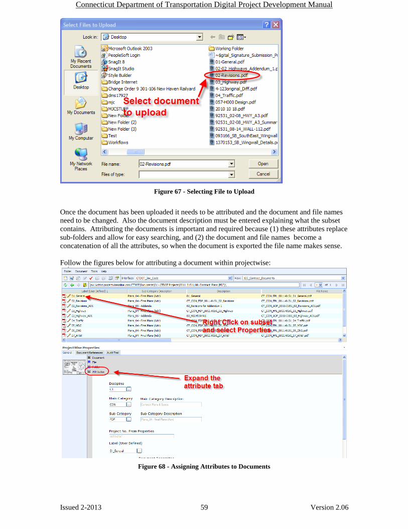
Connecticut Department of Transportation Digital Project Development Manual
Issued 2-2013 59 Version 2.06
Figure 67 - Selecting File to Upload
Once the document has been uploaded it needs to be attributed and the document and file names
need to be changed. Also the document description must be entered explaining what the subset
contains. Attributing the documents is important and required because (1) these attributes replace
sub-folders and allow for easy searching, and (2) the document and file names become a
concatenation of all the attributes, so when the document is exported the file name makes sense.
Follow the figures below for attributing a document within projectwise:
Figure 68 - Assigning Attributes to Documents

Connecticut Department of Transportation Digital Project Development Manual
Issued 2-2013 60 Version 2.06
Figure 69 - Selecting Attributes
Attributes: Discipline: CT
Main Category: CON = Contract Plans & Specs (PDF)
CNS = Contractor Submittal (Working Drawings, Shop Drawings, RFI’s)
Sub Category:
If CON is selected:
FDP = Final Design Plans, DCD = Design Completion Data, DCD2= Design
Completion Data 2, FPL = Final Plans, ADP = Addendum Plans, ACD =
Addendum Completion Data, DCO = Design Initiated Change Order
If CNS is selected:
WDP = Working Drawing for Permanent Structures, WDT = Working Drawings
for Temporary Structures, SHD = Shop Drawing
Label:
Contract Plans
Name of the subset, 01-General for the General subset.
FDP and DCD submittals shall always have the same label.
ADP and ACD submittals shall always have the same label (01-General_A##)
DCO Submittals shall have the label 01-General_C##.
CTDOT standard drawing shall be “CTDOT_HIGHWAY_STD” and
“CTDOT_TRAFFIC_STD”.
For Information Only subsets, FIO must be included in the Label, 11_AT&T_FIO.
Contractor Submittals
Item Number
Description:
Contract Plans
The document description must be entered explaining what the subset contains.
Contractor Submittals
Describe the submittal.

Connecticut Department of Transportation Digital Project Development Manual
Issued 2-2013 61 Version 2.06
After save is selected notice the document and file names match the CTCode and the document
description updates to what was typed in above. You may have to hit refresh to see this change.
Figure 70 - Document Name, Document Description, and File Name
3.2.4 Uploading Documents – Projectwise (Thick Client)
This section gives direction on how to upload and attribute contract documents, for both one
document and multiple documents. All files must be named according to the, naming
conventions in this manual.
3.2.4.1 Uploading and Attributing a Single Document
The following figures give direction on how to upload and attribute files one at a time into
Projectwise:
1. Select the Interface “CTDOT_Attributes” as shown below, if the interface box is not
shown go to View>Toolbars and select interface.
2. Drag and Drop files into the correct folder in the Project.

Connecticut Department of Transportation Digital Project Development Manual
Issued 2-2013 62 Version 2.06
Figure 71 - Uploading Into Projectwise (Thick Client)
3. Select the “Advanced Wizard”
4. Click “Next” until you reach the figure below:
5. Fill in the appropriate attributes as shown below:

Connecticut Department of Transportation Digital Project Development Manual
Issued 2-2013 63 Version 2.06
Figure 72 - Attributing (Thick Client)
Attributes: Discipline: CT
Main Category: CON = Contract Plans & Specs (PDF)
CNS = Contractor Submittal (Working Drawings, Shop Drawings, RFI’s)
Sub Category:
If CON is selected:
FDP = Final Design Plans, DCD = Design Completion Data, DCD2= Design
Completion Data 2, FPL = Final Plans, ADP = Addendum Plans, ACD =
Addendum Completion Data, DCO = Design Initiated Change Order
If CNS is selected:
WDP = Working Drawing for Permanent Structures, WDT = Working Drawings
for Temporary Structures, SHD = Shop Drawing
Label:
Contract Plans
Name of the subset, 01-General for the General subset.
FDP and DCD submittals shall always have the same label.
ADP and ACD submittals shall always have the same label (01-General_A##)
DCO Submittals shall have the label 01-General_C##.
CTDOT standard drawing shall be “CTDOT_HIGHWAY_STD” and
“CTDOT_TRAFFIC_STD”.
For Information Only subsets, FIO must be included in the Label, 11_AT&T_FIO.
Contractor Submittals
Item Number
Description:
Contract Plans
The document description must be entered explaining what the subset contains.
Contractor Submittals
Describe the submittal.

Connecticut Department of Transportation Digital Project Development Manual
Issued 2-2013 64 Version 2.06
6. On the Document Properties page nothing needs to be edited. There is a tool that will
copy the CTCode into the New document name and New document file name fields.
7. On the create document page click next and the document will be uploaded into
Projectwise.
8. Once the document is uploaded the user may need to click F5 (refresh) to see the file
name update.
3.2.5 Combining and Uploading Contract Specifications and CSI Special Provisions
For projects that are led by a consultant designer, FDP and Addendum Contract specifications
and CSI Special Provisions shall be placed in (1) zipped folder. For projects that are led by a
CTDOT design unit, FDP and Addendum Contract specifications and CSI Special Provisions
shall be placed in individual zipped folders per discipline.
Addendum specifications shall be placed in (1) zipped folder. Each page of the specification
section shall be marked in the bottom right corner with “Addendum No. Y”, where “Y” equals
the addendum number.
Design Initiated Change Orders specifications shall be placed in (1) PDF document with a “C#”
and the date in the right side of the header. An example would be, “Rev. C1 - 01/01/10”.
The following shows an example of a consultant designed project, but the process shall also be
followed for a CTDOT designed project.
See the figures below for how to zip a folder:
1. Place all specifications (word documents) in one folder.
2. Right click on the folder and select “Compress to” option shown below:
Figure 73 - Compress Spec. Folder
Specifications shall be submitted in a zipped folder for every submittal into Projectwise.
Submittals include FDP, revised FDP specifications, Addendum specifications, and revised
addendum specifications. Revised FDP and addendum submissions shall only include the revised
specifications.

Connecticut Department of Transportation Digital Project Development Manual
Issued 2-2013 65 Version 2.06
Submitting Contract Specifications
Once logged into Projectwise the final contract specifications shall be submitted as follows:
1. Drag and Drop the zipped specifications folder into the 240_Contract Development
Folder or the pdf of the change order specs into the 110_Contract Specifications folder.
2. Use the advanced wizard and select the attributes as follows:
Discipline = CT
Main Category= CON
Sub-Category =
Label:
Consultant projects
FDP Specs – Should be “FDP Specs” or “Revised FDP Specs”
Addendum Specs – Should be “ASP# Specs” or “Revised ASP# Specs”
Construction Orders – Should be “C# Specs”
CTDOT Designed Projects
FDP Specs – Should be “Discipline_FDP_Specs” (Discipline = HWY, SB, TR,
etc.) Example = “HWY_FDP_Specs.” or for a revised spec package
“Revised_HWY_FDP_Specs.
Addendum Specs – Should be same as FDP specs but change to ASP or ASR.
Example = “HWY_ASP#_Specs” or “Revised_HWY_ASP#_Specs.”
Construction Orders – Should be “C# Specs”
3. Click next until the document is uploaded. The document name and file name will be
automatically updated to match the CTCode when Projectwise is refreshed.
3.2.6 Uploading Supplemental Contract Documents Supplemental Contract Documents shall be submitted into the 240_Contract Development folder
in Projectwise. These documents shall be attributed in accordance with the table below:
Document Discipline
Main
Category
Sub-
Category Label
Proposal Estimate CT DAT EST Proposal
Proposal Esitmate Checklist CT DOC MDO
Proposal Estimate
Checklist
Federal Estimate CT DAT EST Federal
Calendar Day Estimate CT DAT EST Calendar Day
Final Design Report CT DOC RPT Final Design
Categorical Exclusion CT DOC AVL CAT EX
Design Approval Letter CT DOC AVL Design AVL Letter
Environmental Permits CT DOC AVL ENV Permits Name
DBE/SBE Approval with
percentage CT DOC AVL DBE_SBE
Commitment list CT DOC AVL Commitment List
Agreements CT DOC AGR
Make specific to what
type of agreement
Proprietary Item Approval CT DOC AVL Proprietary Item
Standalone Transportation
Management Plan Document,
taken from the final design
report CT DOC MDO Trans. Man. Plan
Table 2 - Supplemental Contract Documents
FSP FDP Specs.
FSR Revised FDP Specs. or Additional FDP Specs
ASP Addendum Specs.
ASR Revised Addendum Specs.
CSP Design Initiated Change Orders

Connecticut Department of Transportation Digital Project Development Manual
Issued 2-2013 66 Version 2.06
If a supplemental document is revised, a new revised document shall be uploaded into
projectwise following the above attribution with the addition of “Revised” being included in the
Label. The only exception shall be the “PW Submittal Checklist” do not include “Revised” in
that submittal.
The document name and file name will automatically update to match the CTCode when
Projectwise is refreshed.
3.2.7 CTDOT Contracts Finalizing of Contract Specifications
CTDOT Contracts shall finalize the specifications working in the 110_Contracts_Specifications
Folder following this workflow CTDOT Contracts Workflow.
3.2.8 Notification of Submittals
When Contract Plans, Specifications, and supplemental contract documents are submitted into
Projectwise the applicable personnel must be notified as follows as applicable:
1. For consultant designed projects, the consultant will notify their Liaison Engineer, who
will then notify, by memorandum, processing that contract plans or specifications have
been submitted for review.
2. For state design projects, the project manager will notify, by memorandum, processing
that contract plans and specifications have been submitted.
3.2.9 Contract Plans Workflow (FDP - Advertise) Table 3-3 below shows how final digital design plans (FDP) flow from delivery through
processing to their final state in advertising.
Processing personnel shall use the following workflow: Projectwise for Processing
Final Design Submission (Subsets)
Step Group Responsibilities of Group
1
Designer -Submits FDP subsets into the 100_Contract Plans folder.
2
Processing (CTDOT) - Change FDP subsets to the Processing State and digitally mark up with comments and save FDP plans. Keep FDP
Plans in the Processing State. If there are no comments proceed to step 7. - Create a comment report of these comments and save on your computers desktop. Then upload and attribute this report correctly into the 240_Contract_Development folder.
3
Designer - Change subsets to reflect comments made by Processing - Submits DCD subsets
4
Processing (CTDOT)
- Change DCD subsets to Processing state - Perform a document compare on the FDP and DCD plans using Bluebeam. - Digitally markup DCD subsets with comments and save. If there are no comments proceed to step 7. - Create a comment report of these comments and save on your computers desktop. Then upload and attribute this report correctly into the 240_Contract_Development folder.
5
Designer - Change subsets to reflect comments made by Processing on DCD Plans - Submits DCD2 subsets

Connecticut Department of Transportation Digital Project Development Manual
Issued 2-2013 67 Version 2.06
6
Processing (CTDOT)
- Changes DCD2 subsets to Processing state - Perform a document compare on the DCD and DCD2 plans using Bluebeam. - Digitally markup DCD2 subsets with comments. If there are no comments proceed to step 7. - Create a comment report of these comments and save on your computers desktop. Then upload and attribute this report correctly into the 240_Contract_Development folder.
7
Processing (CTDOT)
- Change the Sub Category Attribute of the approved subset from FDP or DCD(1,2..etc.) plans to FPL plans. STD and FIO plans shall not be change to FPL. - Copy the CTCode and make the document and file name the CTCode. Make sure the file name has a “.pdf” on the end. -If is a CTDOT Design project, change all discipline subsets to the Manager and Engineering Admin. Sign State. Notify Designer they have to have Manager and Engineering Admin sign the title sheet. When the Designer notifies processing these signatures have been applied to the title sheet, change all discipline subsets to the Advertise state. -If is a Consultant Designed Project, change discipline subsets to Advertise State. -Delete all previous versions of plans, FDP, DCD, DCD2, etc. -Keep Comment reports in the 240_Contract_Development folder for records if necessary -Formally notify Contracts when all subset have been approved for Advertising
Table 3-3 Workflow for CTDOT Processing Unit (Contract Drawings)
3.2.10 ProjectWise Project folder Security
Through the use of Workflows and States, Projectwise can provide dynamic securities to a folder
or document. Dynamic security allows a different level of security to each document at various
phases of its life cycle. This allows a document to reside in one location, in Projectwise, through
out the project life cycle.
3.2.11 100_Contract_Plans (PDF) Folder (Dynamic Security)
During the design submittal process the Projectwise workflow, “Contract Plans Processing”, shall
be applied to this folder. This workflow allows three different states (securities settings) to be
applied to documents within this folder. Each state provides a unique security. The CTDOT
Contracts Processing Unit shall determine which state a document in this folder shall be in.
The “Contract Plans Processing” workflow contains the following security states:
Document Transfer State – allows either the Consultant or State Designer to upload, read and
alter a document.
Processing State – Allows only the processing unit read, write access, allowing them to review
the documents in a secluded area. All other users shall have read access.
Manager and Engineering Admin. Sign – Allows the Manager and Engineering Administrator
to sign the project Title sheet.
Advertise State - Allows all users file read access, allowing any user to open and read the
document.
Once the contract is awarded to the low bidder (Contractor), the Contract Processing Unit shall
move all the documents into the a new workflow called “Contract Plans Construction Workflow”
which hands control of the documents states to the CTDOT Office of Construction (all offices).
The “Contract Plans Construction” workflow contains the following security states:
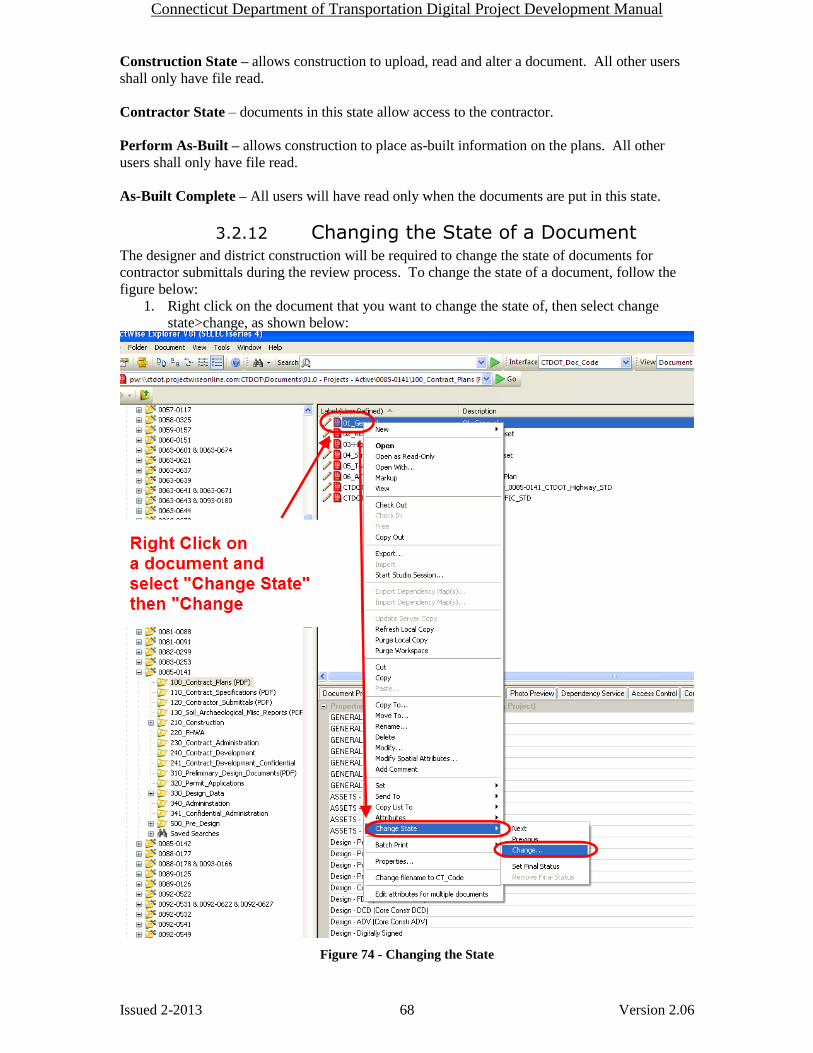
Connecticut Department of Transportation Digital Project Development Manual
Issued 2-2013 68 Version 2.06
Construction State – allows construction to upload, read and alter a document. All other users
shall only have file read.
Contractor State – documents in this state allow access to the contractor.
Perform As-Built – allows construction to place as-built information on the plans. All other
users shall only have file read.
As-Built Complete – All users will have read only when the documents are put in this state.
3.2.12 Changing the State of a Document The designer and district construction will be required to change the state of documents for
contractor submittals during the review process. To change the state of a document, follow the
figure below:
1. Right click on the document that you want to change the state of, then select change
state>change, as shown below:
Figure 74 - Changing the State

Connecticut Department of Transportation Digital Project Development Manual
Issued 2-2013 69 Version 2.06
2. Next drag the file(s) from one state to another as shown below:
Figure 75 - Changing the State
3. Click OK when the comment window opens up and the documents state will change.
Next close the change workflow state window.
4. Notice the “State” column, the state of the documents has been changed.
Figure 76 - State has been Changed

Connecticut Department of Transportation Digital Project Development Manual
Issued 2-2013 70 Version 2.06
Contract Plan and Specification Section 4
Revisions (Addenda and Design Initiated
Change Order)
4.1 Addenda Contract plans that are revised or added due to addenda shall be submitted in digitally signed PDF
discipline subsets containing only the changed sheets. The first sheet of each addendum subsets
shall be digitally signed in a digital signature place holder, that is placed in Microstation as
described in Section 2.0 of this manual, DO NOT ADD an index of drawings sheet. Once
digitally signed the addendum subsets shall be submitted, to the CTDOT, using Projectwise as
described in Section 3.0 of this manual.
Addenda sheets from different subsets cannot be combined and submitted as one subset, they
must be submitted per their respected subsets.
The discipline Addenda subsets shall be attributed as follows, when uploaded into Projectwise
(See Section 3.0): The addenda subset shall have the same label as the original final plan subset
with the addition of (_A##) added to the end, where the ## equals the addenda number. The sub-
category attribute shall be ADP and ACD if the ADP plans are revised. See example below:
PROJECTWISE LABEL
Original Discipline Subset: 04_Traffic
Addenda Discipline Subset: 04_Traffic_A01
2nd Addenda 04_Traffic_A02
6th Addenda 04_Traffic_A06
The contract sheets (previously submitted final plans or earlier addenda plans), being revised by
addenda shall UNOT be modified except; the Engineer of Record shall place an addenda stamp on
the affected sheets. This addenda stamp crosses out the entire sheet with a red X and adds the
following note; "THIS SHEET REPLACED BY ADDENDUM NO."Y"; where "Y" equals the
addendum number. This stamp is placed over digital signatures therefore; removal of the
signatures is not required prior to placing the addenda stamp. For this process see Section 4.4.
WARNING – When placing the stamps, removing the digital signature is not allowed.
The Index of Revisions Sheet(s) located in the 02_Revisions subset(s) shall be managed by the
project manager for all addenda, and submitted as described in Section 4.3.1. A new subset must
be updated for each addendum. For addendums that only affect specifications
A watermark of the signer’s signature; signature only for (CTDOT), or PE Stamp for
(Consultants) shall be placed on all added or revised sheets. See Section 2.2
4.1.1 Revised Plans - Addenda A note shall be placed, directly above the bottom right hand corner of the title block, on the
replacement sheets stating “ADDENDUM NO. “Y”, where “Y” equals the addenda number.
This note is a level in Microstation that needs to be turned on and edited.
Sheet numbers for revised plans shall be as follows:
Original Final Plan Sheet;
Original: 02.25
Addenda 1: 02.25.A1

Connecticut Department of Transportation Digital Project Development Manual
Issued 2-2013 71 Version 2.06
Previous Addenda Sheet;
Original: 02.25.A2
Addenda 4: 02.25.A4
For revised sheets the drawing numbers shall not be modified.
The revision block, located on the revised sheets, shall be completed as follows: A numbered
triangle (revision number) will be placed within the clouded (changed) area and a like numbered
triangle will be placed in the revision block, accompanied by a description of the revision itself.
The revision number is specific to a particular sheet, and increases in consecutive order per
revision and per addenda. If a sheet is changed for the first time under addenda five the revision
number is 1 NOT 5. If it is changed again under addenda 7 the revision number becomes 2.
If a sheet requires further revisions by a subsequent addendum, the addendum shall be prepared,
as detailed above. The previously revised sheet shall now be stamped using Adobe Acrobat after
addendum approval, see Section 4.4.
Note: When preparing an Addendum that will change quantities on a project that
includes a "Detailed Estimate Sheet", never revise the "Detailed Estimate Sheet." A
"Detailed Estimate Sheet" is never included in an addendum. Also, the "Quantities" box
shown on the General Plan sheet for any structure is never to be revised.
4.1.2 New Sheets - Addenda
Changes that require a new sheet(s) to be added to a discipline subset shall be formatted in one of
two ways, as follows:
1. If the new sheet does not have to be placed in a specific location within the discipline
subset, the new sheet shall be placed last, and numbered sequentially from the last sheet
of the discipline subset. The total number of sheets noted on the project plans and
discipline subsets stays the same. A note shall be placed on the new sheet stating, "NEW
SHEET ADDED BY ADDENDUM NO."Y", where "Y" equals the addendum number.
This note shall be located directly above the right hand corner of the title block. This
note is a level in Microstation that needs to be turned on and edited. The revision block
on the added sheet, shall not be filled out.
2. If the designer determines that the new sheet must go in a specific location within the
discipline subset, the new sheet number shall be the number of the previous sheet
followed by (-1.A#), where # is the Addendum Number. For example, if the new sheet
must be placed in a discipline subset right after sheet 02.57, the new sheet shall be
numbered 02.57-1.A1, if an additional sheet needs to be added, in this case it would be
02.57-2.A1. The total number of sheets noted on the project plans stays the same. A
note shall be placed on the new sheet stating, "NEW SHEET ADDED BY ADDENDUM
NO."Y", where "Y" equals the addendum number. This note shall be located directly
above the right hand corner of the title block. This note is a level in Microstation that
needs to be turned on and edited.
When adding a new sheet a new drawing number is also required. As with the sheet
number the drawing number of the new sheet shall be the drawing number of the
previous sheet plus a decimal and the sheet count. For example, if the new drawing must
be placed in the project plans right after drawing number S-5, the drawing number shall
be S-5-1.
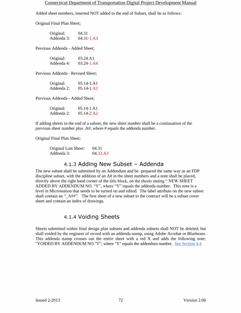
Connecticut Department of Transportation Digital Project Development Manual
Issued 2-2013 72 Version 2.06
Added sheet numbers, inserted NOT added to the end of Subset, shall be as follows:
Original Final Plan Sheet;
Original: 04.31
Addenda 3: 04.31-1.A3
Previous Addenda - Added Sheet;
Original: 03.24.A1
Addenda 4: 03.24-1.A4
Previous Addenda - Revised Sheet;
Original: 05.14-1.A1
Addenda 2: 05.14-1.A2
Previous Addenda - Added Sheet;
Original: 05.14-1.A1
Addenda 2: 05.14-2.A2
If adding sheets to the end of a subset, the new sheet number shall be a continuation of the
previous sheet number plus .A#, where # equals the addenda number.
Original Final Plan Sheet;
Original Last Sheet: 04.31
Addenda 3: 04.32.A3
4.1.3 Adding New Subset – Addenda The new subset shall be submitted by an Addendum and be prepared the same way as an FDP
discipline subset, with the addition of an A# in the sheet numbers and a note shall be placed,
directly above the right hand corner of the title block, on the sheets stating “ NEW SHEET
ADDED BY ADDENDUM NO. “Y”, where “Y” equals the addenda number. This note is a
level in Microstation that needs to be turned on and edited. The label attribute on the new subset
shall contain an “_A##”. The first sheet of a new subset to the contract will be a subset cover
sheet and contain an index of drawings.
4.1.4 Voiding Sheets
Sheets submitted within final design plan subsets and addenda subsets shall UNOT be deleted; but
shall voided by the engineer of record with an addenda stamp, using Adobe Acrobat or Bluebeam.
This addenda stamp crosses out the entire sheet with a red X and adds the following note;
"VOIDED BY ADDENDUM NO.”Y"; where "Y" equals the addendum number. See Section 4.4

Connecticut Department of Transportation Digital Project Development Manual
Issued 2-2013 73 Version 2.06
4.1.5 Addenda Plans Workflow X Table 4-1 Contract Processing Addenda File Workflow for Contract Drawings below shows how
addenda subsets are delivered and processed for advertisement.
Table 4-1 Contract Processing Addenda File Workflow for Contract Drawings
Addendum Plans
Step Group Responsibilities of Group
1
Designer -Submits ADP subsets into the 100_Contract Plans folder.
2
Processing (CTDOT) - Changes document to the Processing State and digitally mark up with comments and save. Keep ADP Plans in the
Processing State. If there are no comments proceed to step 7. - Create a comment report of these comments and save on your computers desktop. Then upload and attribute this report correctly into the 240_Contract_Development folder. Notify the designer when this is finished.
3
Designer - Change subsets to reflect comments made by Processing - Submits ACD Subsets
4
Processing (CTDOT)
- Changes ACD subsets to Processing state - Perform a document compare on the ADP and ACD plans using Bluebeam. - Digitally markup ACD subsets with comments. If there are no comments proceed to step 7. - Create a comment report of these comments and save on your computers desktop. Then upload and attribute this report correctly into the 240_Contract_Development folder. Notify the designer when this is finished.
5
Designer - Change subsets to reflect comments made by Processing on ACD Plans - Submits ACD2 Subsets.
6
Processing (CTDOT)
- Change ACD2 Subsets to Processing state - Perform a document compare on the ACD and ACD2 plans using Bluebeam. - Digitally markup ACD2 subsets with comments. If there are no comments proceed to step 7. - Create a comment report of these comments and save on your computers desktop. Then upload and attribute this report correctly into the 240_Contract_Development folder. Notify the designer when this is finished.
7
Processing (CTDOT)
- Change the Sub Category Attribute of the approved subset from ACD(1,2..etc.) plans to ADP plans - Copy the CTCode and make the document and file name the CTCode. Make sure the file name has a “.pdf” on the end. - Change discipline subsets to the Advertise State. -Delete all previous versions of plans, ADP, ACD, ACD2, etc. -Keep Comment reports in 240_Contract_Development folder for records if necessary - Formally notify Contracts when all subset have been approved for Advertising - Notify the designer that the plans are going to be advertised and they can put the addenda stamps on the affected sheets.

Connecticut Department of Transportation Digital Project Development Manual
Issued 2-2013 74 Version 2.06
4.1.6 Addenda Specifications Contract Specifications that are revised or added due to addenda shall be submitted digitally in
accordance with section 3.2.5.
Addendums that only affect specifications shall be recorded on the 02-Revisions plan subset with
the following options selected:
Rev No. = Addendum number
Sheet No. = NA
Date = Date of Addendum
Check “Rev” for all these cases
Description = “No Change to Plans”
See section 4.3.1 for updating the 02-Revisions set.
4.1.7 Addenda Report Addenda report shall contain all the changes to the plans and specifications and any contractor
questions and answers. This report shall be submitted in Word format into the
240_Contract_Development in Projectwise with the following attributes:
Discipline = CT
Main Category = DOC
Sub Category = RPT
Label = “Addn. No. # Report”, where # is the addendum number. If a report is revised the label
shall include “Rev.” at the end. If the report is revised a second time the label shall include “Rev.
2” at the end, etc.
Description = Give a brief description of the submission.
4.2 Design Initiated Change Order (DCO)
Design Initiated Change Orders (DCO) are change order requests in which the designer alters the
original contract by:
A revision to an existing plan sheet(s) or specification(s)
The addition of a new plan sheet(s) or specification(s)
The deletion of an existing plan sheet(s) or specification(s)
The creation and management of DCO’s shall be as specified in this section.
Contract plans changed or added due to DCO’s shall be submitted in a digitally signed PDF
discipline subsets containing only the added or changed sheets. The first sheet of each DCO
subset shall be digitally signed in a digital signature place holder, that is placed in Microstation as
described in Section 2.0 of this manual, DO NOT ADD a cover sheet. Once digitally signed the
DCO subsets shall be submitted, to the CTDOT, using Projectwise as described in Section 3.0 of
this manual.
DCO sheets from different subsets cannot be combined and submitted as one subset.
The discipline DCO subsets shall be coded as follows, when uploaded into Projectwise (See
Section 3.0): The DCO subset shall have the same name as the original final plan subset with the
addition of (_C###) added to the end, where the ### equals the DCO number. The sub-category
attribute shall be DCO (Design Initiated Change Order) See Examples below:
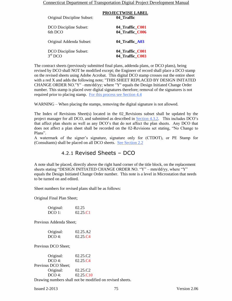
Connecticut Department of Transportation Digital Project Development Manual
Issued 2-2013 75 Version 2.06
PROJECTWISE LABEL Original Discipline Subset: 04_Traffic
DCO Discipline Subset: 04_Traffic_C001
6th DCO 04_Traffic_C006
Original Addenda Subset: 04_Traffic_A03
DCO Discipline Subset: 04_Traffic_C001
3rd
DCO 04_Traffic_C003
The contract sheets (previously submitted final plans, addenda plans, or DCO plans), being
revised by DCO shall UNOT be modified except; the Engineer of record shall place a DCO stamp
on the revised sheets using Adobe Acrobat. This digital DCO stamp crosses out the entire sheet
with a red X and adds the following note; "THIS SHEET REPLACED BY DESIGN INITATED
CHANGE ORDER NO."Y" –mm/dd/yy; where "Y" equals the Design Initiated Change Order
number. This stamp is placed over digital signatures therefore; removal of the signatures is not
required prior to placing stamp. For this process see Section 4.4
WARNING – When placing the stamps, removing the digital signature is not allowed.
The Index of Revisions Sheet(s) located in the 02_Revisions subset shall be updated by the
project manager for all DCO, and submitted as described in Section 4.3.2. This includes DCO’s
that affect plan sheets as well as any DCO’s that do not affect the plan sheets. Any DCO that
does not affect a plan sheet shall be recorded on the 02-Revisions set stating, “No Change to
Plans”.
A watermark of the signer’s signature, signature only for (CTDOT), or PE Stamp for
(Consultants) shall be placed on all DCO sheets. See Section 2.2
4.2.1 Revised Sheets – DCO
A note shall be placed, directly above the right hand corner of the title block, on the replacement
sheets stating “DESIGN INITIATED CHANGE ORDER NO. “Y” – mm/dd/yy, where “Y”
equals the Design Initiated Change Order number. This note is a level in Microstation that needs
to be turned on and edited.
Sheet numbers for revised plans shall be as follows:
Original Final Plan Sheet;
Original: 02.25
DCO 1: 02.25.C1
Previous Addenda Sheet;
Original: 02.25.A2
DCO 4: 02.25.C4
Previous DCO Sheet;
Original: 02.25.C2
DCO 4: 02.25.C4
Previous DCO Sheet;
Original: 02.25.C2
DCO 4: 02.25.C10
Drawing numbers shall not be modified on revised sheets.

Connecticut Department of Transportation Digital Project Development Manual
Issued 2-2013 76 Version 2.06
Approval blocks on all new sheets shall be watermarked with a signature (CTDOT) or PE Stamp
(Consultant) and the first sheet of the subset shall be digitally signed in accordance with Section 2
of this document.
4.2.2 New Sheets - DCO Changes that require new sheet(s) to be added to a discipline subset shall be formatted in one of
two ways, as follows:
1. If the new sheet does not have to be placed in a specific location within a discipline
subset, the new sheet shall be numbered sequentially from the last sheet of the discipline
subset. The total number of sheets noted on the project plans and discipline subsets stays
the same. A note shall be placed on the new sheet stating, “NEW SHEET ADDED BY
DESIGN INITIATED CHANGE ORDER NO. Y – mm/dd/yy” where “mm/dd/yy”
equals the month, day and year the change order request was submitted. This note shall
be located directly above the title block. This note is a level in Microstation that needs to
be turned on and edited.
2. If the designer determines that the new sheet belongs in a specific location within a
discipline subset, the new sheet number shall be the number of the sheet it most closely
relates to followed by (-1.C#). For example, if the new drawing should reside in the
03_Highway discipline subset right after sheet 03.57, the new sheet shall be numbered
03.57-1.C#.
3. The total number of sheets noted on the project plans stays the same. A note shall be
placed on the new sheet stating, “NEW SHEET ADDED BY DESIGN INITIATED
CHANGE ORDER NO. Y – mm/dd/yy” where “mm/dd/yy” equals the month, day and
year the change order request was submitted. This note shall be located directly above
the bottom right hand corner of the title block. This note is a level in Microstation that
needs to be turned on and edited.
When adding a new sheet a new drawing number is also required. The drawing number
of the new sheet shall be the drawing number of the sheet it most closely relates to
followed by (-#). For example, if the new drawing must be placed in the project plans
right after drawing number HWY-10, the drawing number shall be HWY-10-1.
Added sheet numbers, to a specific location, shall be as follows:
Original Final Plan Sheet;
Original: 04.31
DCO 3: 04.31-1.C3
Previous Addenda – Added Sheet;
Original: 03.24.A1
DCO 4: 03.24-1.C4
Previous DCO – Revised Sheet;
Original: 02.45.C1
DCO 2: 02.45.C2

Connecticut Department of Transportation Digital Project Development Manual
Issued 2-2013 77 Version 2.06
Previous Addenda - Added Sheet;
Original: 05.14-1A1
DCO 2: 05.14-2.C2
Previous DCO – Added Sheet;
Original: 02.45-1.C1
DCO 2: 02.45-2.C2
If adding sheets to the end of a subset, the new sheet number shall be a continuation of the
previous sheet number plus C#., where # equals the Design Initiated Change Order Request
number.
Original Final Sheet
Original Last Sheet: 04.35
DCO 4: 04.36.C4
4.2.3 New Subset – DCO The new subset shall be submitted by DCO and be prepared the same way as an FDP discipline
subset, with the addition of an C# in the sheet numbers and a note shall be placed, directly above
the right hand corner of the title block, on the replacement sheets stating “NEW SHEET ADDED
BY DESIGN INITIATED CHANGE ORDER NO. “Y” – mm/dd/yy, where “Y” equals the
Design Initiated Change Order number. This note is a level in Microstation that needs to be
turned on and edited. The label attribute shall contain “_C##”. The first sheet of a new subset to
the contract will be a subset cover sheet and contain an index of drawings.
4.2.4 Voided Sheets Sheets submitted within final design plan subsets, addenda subsets, or design initiated change
order subsets shall UNOT be deleted; but shall be voided by the engineer of record, with a DCO
stamp using Adobe Acrobat or Bluebeam. This DCO stamp crosses out the entire sheet with a red
X and adds the following note; "VOIDED BY DESIGN INTIATED CHANGE ORDER NO. Y –
mm/dd/yy; where "Y" equals the Design Initiated Change Order number. See Section 4.4
4.2.5 DCO Specifications Design Initiated Change Orders specifications shall be placed in (1) PDF document with a “C#”
and the date in the right side of the header. An example would be, “Rev. C1 - 01/01/10”.
DCOs that only affect specifications shall be recorded on the 02-Revisions plan subset with the
following options selected:
Rev No. = DCO number
Sheet No. = NA
Date = Date of DCO
Check Rev for all these cases
Description = “No Change to Plans”
See section 4.3.2 for updating the 02-Revisions set.
Specifications shall be created in accordance with the Departments policies and procedures for
Contract Development. The Engineer shall also combine all specifications into (1) PDF
document and upload that into the 110_Contract Specifications (PDF) folder in Projectwise
following section 3.2.5.

Connecticut Department of Transportation Digital Project Development Manual
Issued 2-2013 78 Version 2.06
4.3 02_Revisions Subset The project manager is responsible for managing this subset. Each project has a 02_Revisions
subset and this subset only contains the, “Index of Revisions Sheet(s)”. These revision sheets are
used for tracking all sheet changes due to addenda (ADP) and Design Initiated Change Order
(DCO) with respect to the entire project. The 02_Revisions subset starts out as an un-signed
blank place holder in the project. The figure below is an example of a blank 02_Revisions subset:
Figure 77 - Blank 02-Revisions Subset
ADDENDA:
When the project requires an Addendum, the Project Manager must record these changes on a
NEW 02_Revisions_A## subset, where A## equals the Addendum ##. New 02-Revisions
subsets shall contain all previous Addendum information. For example, Addendum 4 shall
include all changes made from Addendums 1, 2, 3 and 4.
DESIGN INITIATED CHANGE ORDER:
When a project requires a Design Initiated Change Order (DCO), the following process shall be
followed:
For the first DCO, the Project Manager shall prepare a NEW 02_Revisions_DCO subset. For
each subsequent DCO, the Project Manager shall AMMEND the previous 02_Revisions_DCO
subset. 02_Revisions_DCO subsets shall always contain all previous Addendum information and
the new DCO information. For example, when DCO #1 is prepared, the 02_Revision_DCO
subset shall include all Addendum information as well as the changes made for DCO #1.
The following figures are an example of the “Index of Revisions Sheet(s)” completed up to
Addendum #3:

Connecticut Department of Transportation Digital Project Development Manual
Issued 2-2013 79 Version 2.06
Figure 78 - Index of Revisions Sheet
Detail A from figure 1 shows the information typed in for a change to the contract plans. The
project designer inputs the Addendum or DCO number, the sheet number, the date, a description
of the change, the person who made the change, and checks the appropriate box for: new sheet
added, revised sheet or deleted sheet.
Figure 79 - Detail A
Detail B from figure 1 shows the title block information.
Figure 80 - Detail B

Connecticut Department of Transportation Digital Project Development Manual
Issued 2-2013 80 Version 2.06
4.3.1 02_Revisions Subset Workflow - Addenda Each time an addendum is issued, the “Index of Revisions sheet” must be updated by the Project
Manager as follows:
1. The user will export/download the latest 02_Revisions subset out of Projectwise to their
local computer.
2. With your digital signature USB key inserted within the USB, right click on the Signature
Box and select Clear Signature as shown below, this is the first Addendum this step can
be skipped since the subset will not have a signature on it:
Figure 81 Clearing the Digital Signature
3. Enter the information into form fields as described in section 4.3.4.
4. Add note “ADDENDUM NO. Y” in the bottom right hand corner of the sheet above the
title block, where Y = the Addendum number.
5. Add new revision sheet each time previous sheet becomes full. Add note “NEW SHEET
ADDED BY ADDENDUM NO. “Y”, where “Y” equals the addenda number. Follow
section 4.3.3 of this document.
6. When finished sign using a certifying signature as shown in Section 2.6.2
7. Upload the document into Projectwise.
8. Attribute the subset: Main Category = CON, Sub-Category = ADP, Label =
02_Revisions_A##
9. Make the document description 02_Revisions_A#.
4.3.2 02_Revisions Subset Workflow - DCO Preparing the 02_Revision subset for the first DCO the Project Manager shall follow the
workflow for preparing the addendum 02_Revision subset, see section 4.3.1 amended as follows:
Step 4 becomes: Add note “DESIGN INITIATED CHANGE ORDER NO. Y –
mm/dd/yy” in the bottom right hand corner.
Step 8 becomes: attribute the subset: Main Category = CON, Sub-Category = DCO,
Label = 02_Revisions_DCO.
Step 10 becomes: Make the document description 02_Revisions_DCO.
The following workflow shall be used by the Project Manager for recording subsequent change
DCOs to the 02_Revisions_DCO subset. In this workflow the user edits the subset in
Projectwise, they do not have to export the document out and submit a new subset:

Connecticut Department of Transportation Digital Project Development Manual
Issued 2-2013 81 Version 2.06
1. Check out the 02_Revisions_DCO subset from Projectwise.
2. Follow steps 2 through 7 from section 4.3.1 amended as follows:
a. In step 4 edit note “DESIGN INITIATED CHANGE ORDER NO. Y -
mm/dd/yy”
b. In step 5 add note “NEW SHEET ADDED BY DESIGN INITIATED CHANGE
ORDER NO. Y – mm/dd/yy”
c. In step 7 “Check In” the document into Projectwise
4.3.3 Adding a New Revisions Sheet to the 02_Revisions Subset
4.3.3.1 Adobe Adding New Revisions Sheet This section shall be used when a new sheet is to be added to the 02_Revisions Subset
(Addendum and DCO)
See Section 1.4 step 16 for link to “Index of Revisions Sheet”
1. In the open Index of Revisions sheet select, File>Print.
2. Choose the Adobe PDF printer and select OK as shown below:
Figure 82 - Selecting the PDF Printer
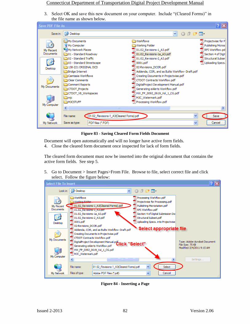
Connecticut Department of Transportation Digital Project Development Manual
Issued 2-2013 82 Version 2.06
3. Select OK and save this new document on your computer. Include “(Cleared Forms)” in
the file name as shown below.
Figure 83 - Saving Cleared Form Fields Document
Document will open automatically and will no longer have active form fields.
4. Close the cleared form document once inspected for lack of form fields.
The cleared form document must now be inserted into the original document that contains the
active form fields. See step 5.
5. Go to Document > Insert Pages>From File. Browse to file, select correct file and click
select. Follow the figure below:
Figure 84 - Inserting a Page
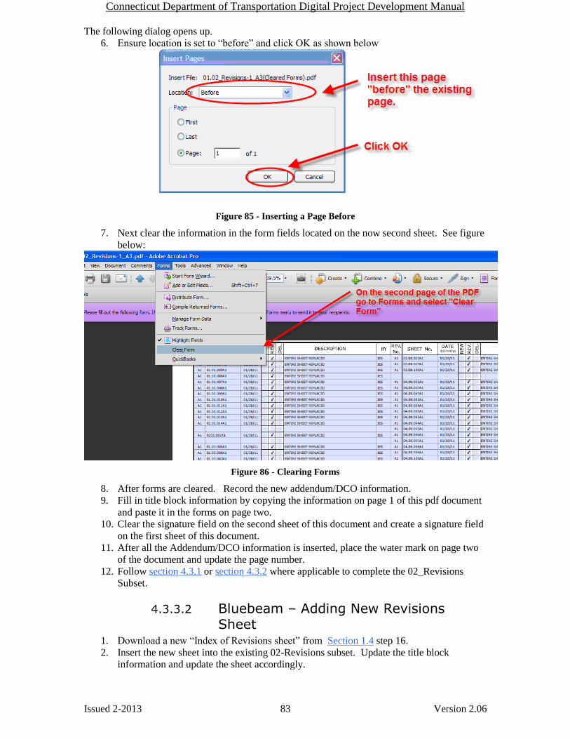
Connecticut Department of Transportation Digital Project Development Manual
Issued 2-2013 83 Version 2.06
The following dialog opens up.
6. Ensure location is set to “before” and click OK as shown below
Figure 85 - Inserting a Page Before
7. Next clear the information in the form fields located on the now second sheet. See figure
below:
Figure 86 - Clearing Forms
8. After forms are cleared. Record the new addendum/DCO information.
9. Fill in title block information by copying the information on page 1 of this pdf document
and paste it in the forms on page two.
10. Clear the signature field on the second sheet of this document and create a signature field
on the first sheet of this document.
11. After all the Addendum/DCO information is inserted, place the water mark on page two
of the document and update the page number.
12. Follow section 4.3.1 or section 4.3.2 where applicable to complete the 02_Revisions
Subset.
4.3.3.2 Bluebeam – Adding New Revisions Sheet
1. Download a new “Index of Revisions sheet” from Section 1.4 step 16.
2. Insert the new sheet into the existing 02-Revisions subset. Update the title block
information and update the sheet accordingly.

Connecticut Department of Transportation Digital Project Development Manual
Issued 2-2013 84 Version 2.06
4.3.4 Filling Out Revision Index Sheet To fill out a form field simply click on the box and begin typing. The first column is the
Addendum or Design Initiated Change Order. The second column is the revised or new sheet
number. The third column is the date, followed by a brief description that is similar to the
description on the actual sheet being revised. Finally click in the appropriate check box per row to
describe the action taken, new sheet, revised sheet, or sheet deleted. Note: The Engineer is not
required to input changes numerically by Sheet No. If another changed sheet is added to an
Addendum in the eleventh hour, it can be placed at the bottom of the list on the “Index of
Revisions Subset”.
Figure 87 Modifying the “Index of Revisions Subset”
4.4 Placing Stamps on Affected Sheets – Revised, or Deleted Sheets
A digital stamp that crosses out the entire sheet shall be place on digital contract sheets that are
affected by Addenda or Design Initiated Change Order. The stamp shall be placed using Adobe
Acrobat Custom Stamps tools or Bluebeam Stamp tools. In addition to crossing out the sheet this
stamp includes an area for the note. The note shall describe the action responsible for the revision.
See section 7.3 for PDF stamps.
WARNING – When placing the stamps, removing the digital signature is not allowed.
XTable 4-1 below lists the notes that shall be used for addenda, construction order requests, and as
built notes. These notes should be used in conjunction with the cross-out stamp.
Table 4-1 Modifications to Existing Sheets by Addendum, Construction Orders and As-Builts
Addendum Notes Description of Use
THIS SHEET REPLACED BY ADDENDUM NO. Y The revised sheet is considered to replace, in
total, the original sheet.
VOIDED BY ADDENDUM NO. Y Sheet is voided by Addendum.
Design Initiated Change Order Notes Description of Use
THIS SHEET REPLACED BY DESIGN INITIATED
CHANGE ORDER NO. Y – mm/dd/yy
Used for revisions to existing sheets. Changes
must be noted only on the revised sheet.
VOIDED BY DESIGN INITIATED CHANGE ORDER NO. Y – mm/dd/yy
Use this for voiding of existing sheets.

Connecticut Department of Transportation Digital Project Development Manual
Issued 2-2013 85 Version 2.06
Figure 88 Typical Sheet Replaced by Addendum 1
Figure 89 Typical Sheet Replaced by DCO
Connecticut Department of Transportation Digital Project Development Manual
Issued 2-2013 86 Version 2.06
As-Built Comments - Final Plans Section 5
As stated in the CTDOT’s Construction Manual chapter 1-313 “Final Revisions of Plans and
Cross Sections”, it is the responsibility of either the Contracting Engineers (Consultant
Inspectors) or State Forces (Office of Construction) to perform final as-built revisions of Contract
Plans. As-Built revisions shall be recorded in accordance with Chapter 1-313 of the Construction
Manual, amended as follows:
Final as-built revisions will be applied to the digitally signed PDF plans as a digital
comment, using Adobe or Bluebeam’s commenting tools. Digital comments are placed
over the top of the digital signature and its security, therefore, the original content of the
PDF plans can never be altered. Because as-built comments are digital and placed over
the top of the plans they are easily recognizable, searchable, and may be turned off if
necessary.
As-built comments shall be applied to the original, addenda, or construction order plans,
whichever sheet is the latest. The original, addenda and construction orders PDF plans
are located in ProjectWise within the active project’s 100_Contract Plans folder.
CAD drawings may be updated, at the discretion of each design office, to reflect any
addenda, change orders, and as-built revisions for use in the future; however the original
digitally signed as-built PDF plans shall not be replaced and shall be the PDF set for
permanent records.
5.1 As-Built Revisions (Digital Comments) Workflow
Two methods for applying as-built revisions to the digital PDF plans are provided in the
following sections; 5.1.1 and 5.1.2.
The first method is Section 5.1.1Post Construction. District staff shall record as-built
revisions on their record set (paper copies) during construction. Once construction is
completed these revisions shall then be applied as comments to the digital PDF per the
following workflow.
The second method, using Section 5.1.2Active As-Built, district staff shall record as-built
revisions on their record set (paper copies), and shall apply them as comments to the final
set of digital PDF plans on an intermittent bases during construction. By using this
method as-built information becomes available to all parties that have access to
ProjectWise during the construction process, improving communication and
transparency.
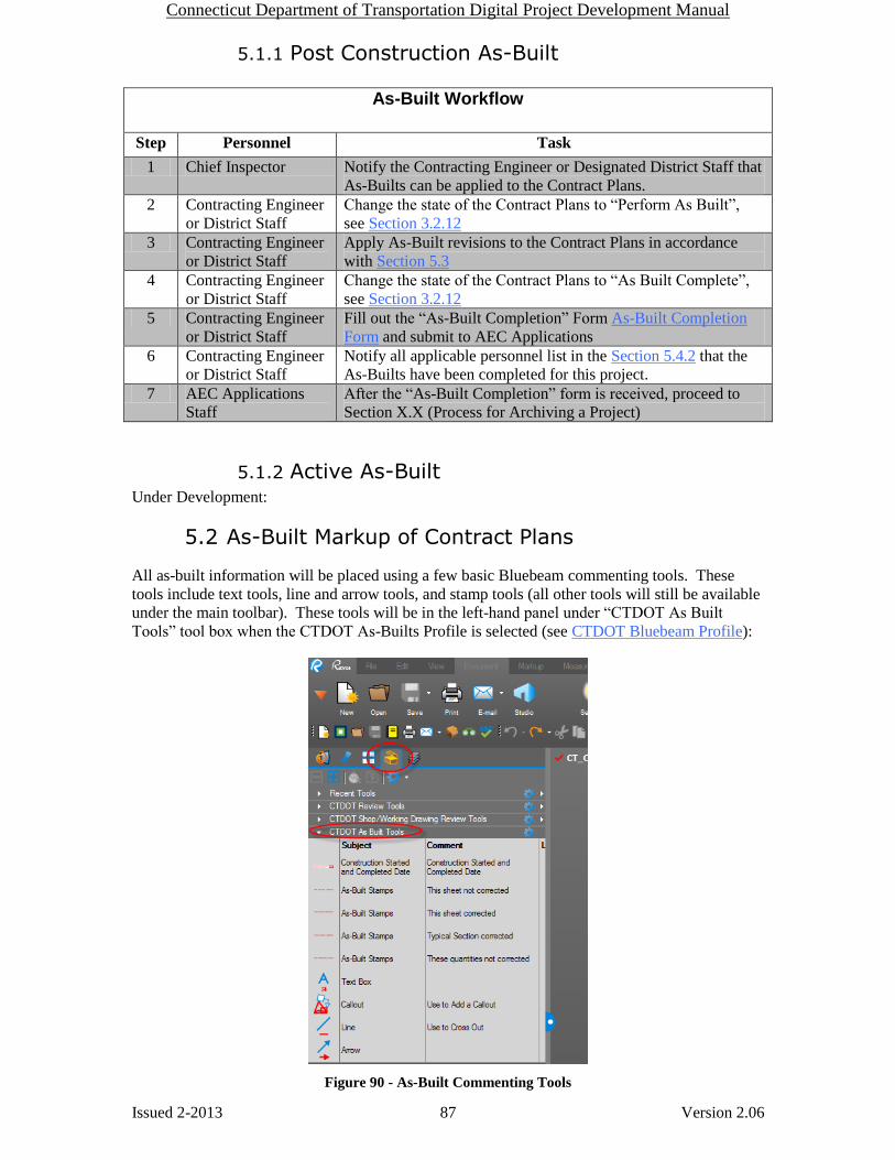
Connecticut Department of Transportation Digital Project Development Manual
Issued 2-2013 87 Version 2.06
5.1.1 Post Construction As-Built
As-Built Workflow
Step Personnel Task
1 Chief Inspector Notify the Contracting Engineer or Designated District Staff that
As-Builts can be applied to the Contract Plans.
2 Contracting Engineer
or District Staff
Change the state of the Contract Plans to “Perform As Built”,
see Section 3.2.12
3 Contracting Engineer
or District Staff
Apply As-Built revisions to the Contract Plans in accordance
with Section 5.3
4 Contracting Engineer
or District Staff
Change the state of the Contract Plans to “As Built Complete”,
see Section 3.2.12
5 Contracting Engineer
or District Staff
Fill out the “As-Built Completion” Form As-Built Completion
Form and submit to AEC Applications
6 Contracting Engineer
or District Staff
Notify all applicable personnel list in the Section 5.4.2 that the
As-Builts have been completed for this project.
7 AEC Applications
Staff
After the “As-Built Completion” form is received, proceed to
Section X.X (Process for Archiving a Project)
5.1.2 Active As-Built Under Development:
5.2 As-Built Markup of Contract Plans
All as-built information will be placed using a few basic Bluebeam commenting tools. These
tools include text tools, line and arrow tools, and stamp tools (all other tools will still be available
under the main toolbar). These tools will be in the left-hand panel under “CTDOT As Built
Tools” tool box when the CTDOT As-Builts Profile is selected (see CTDOT Bluebeam Profile):
Figure 90 - As-Built Commenting Tools

Connecticut Department of Transportation Digital Project Development Manual
Issued 2-2013 88 Version 2.06
5.3 Applying As-Built Comments to Contract Plans
5.3.1 Before Using Bluebeam for As-Builts All CTDOT users are required to complete the steps in Appendix A prior to applying as-built revisions. By completing these steps as-built revisions will be standardized across the all CTDOT users. These steps only need to be completed the first time using Bluebeam or when the user logs into a new computer.
Perform the initial login steps for Bluebeam. Initial Log Into Bluebeam
Download the CTDOT Bluebeam profile. Download CTDOT Bluebeam Profile
The user must have a ProjectWise login/password. Contact Julie Annino if you do
not have a Projectwise Username and Password.
5.3.2 Opening the Contract Plans from Projectwise The contract plans are located in the 100_Contract_Plans folder of the project in Projectwise, as
shown below:
Figure 91 - Location of the Contract Plans in Projectwise
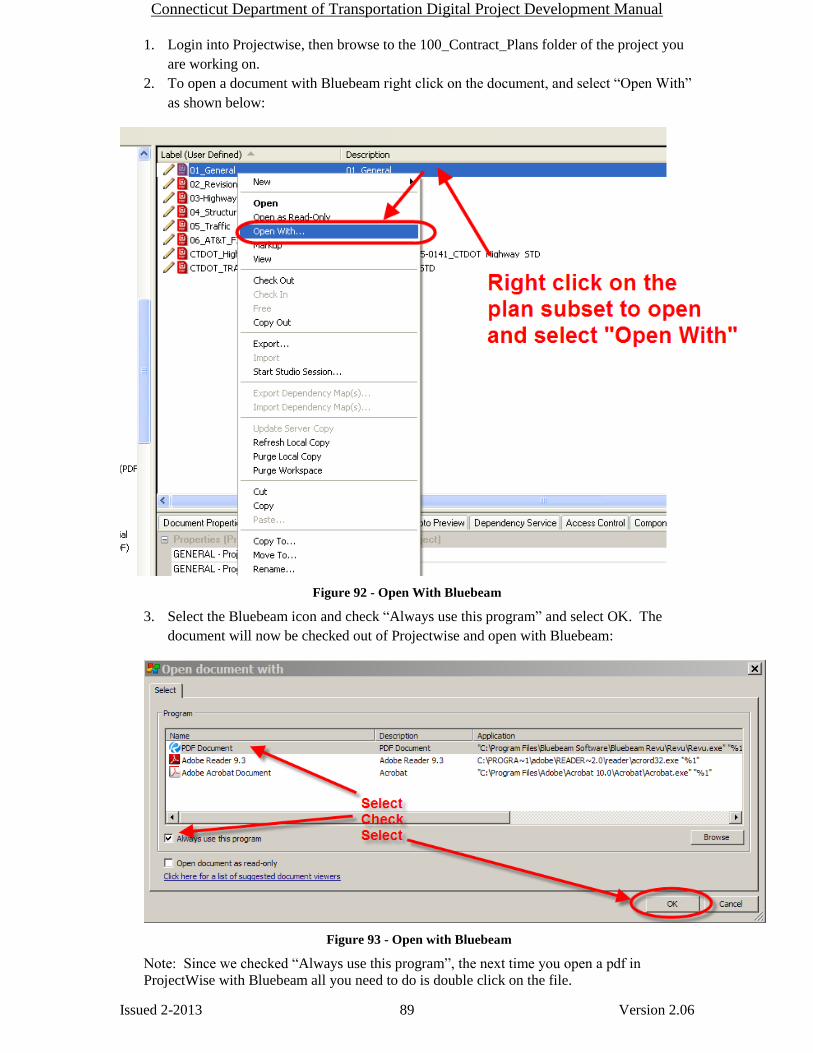
Connecticut Department of Transportation Digital Project Development Manual
Issued 2-2013 89 Version 2.06
1. Login into Projectwise, then browse to the 100_Contract_Plans folder of the project you
are working on.
2. To open a document with Bluebeam right click on the document, and select “Open With”
as shown below:
Figure 92 - Open With Bluebeam
3. Select the Bluebeam icon and check “Always use this program” and select OK. The
document will now be checked out of Projectwise and open with Bluebeam:
Figure 93 - Open with Bluebeam
Note: Since we checked “Always use this program”, the next time you open a pdf in
ProjectWise with Bluebeam all you need to do is double click on the file.

Connecticut Department of Transportation Digital Project Development Manual
Issued 2-2013 90 Version 2.06
4. After the As-Builts are applied to the contract plans click save in Bluebeam and then
select “Check In” when a projectwise dialog box pops up. If the document is not checked
back into Projectwise the As-Builts will not be uploaded to Projectwise.
5.3.3 Applying Digital As-Built Stamps
5.3.3.1 Construction Started & Completed Dates The construction started and complete date stamps must be applied to the PDF title sheet, located
in the 01_General subset, as stated below:
1. Select the ”ConstructionStartedandCompletedDates”: stamp from the “CTDOT As
Built Tools” tool box and place it at a conspicuous location on the title sheet:
Figure 94 - Construction Started and Completed Date Stamp
2. Enter Start and Completed dates in a mm/dd/yyyy format with a space between them and
select OK:
Figure 95 - Entering the Dates for the Stamp
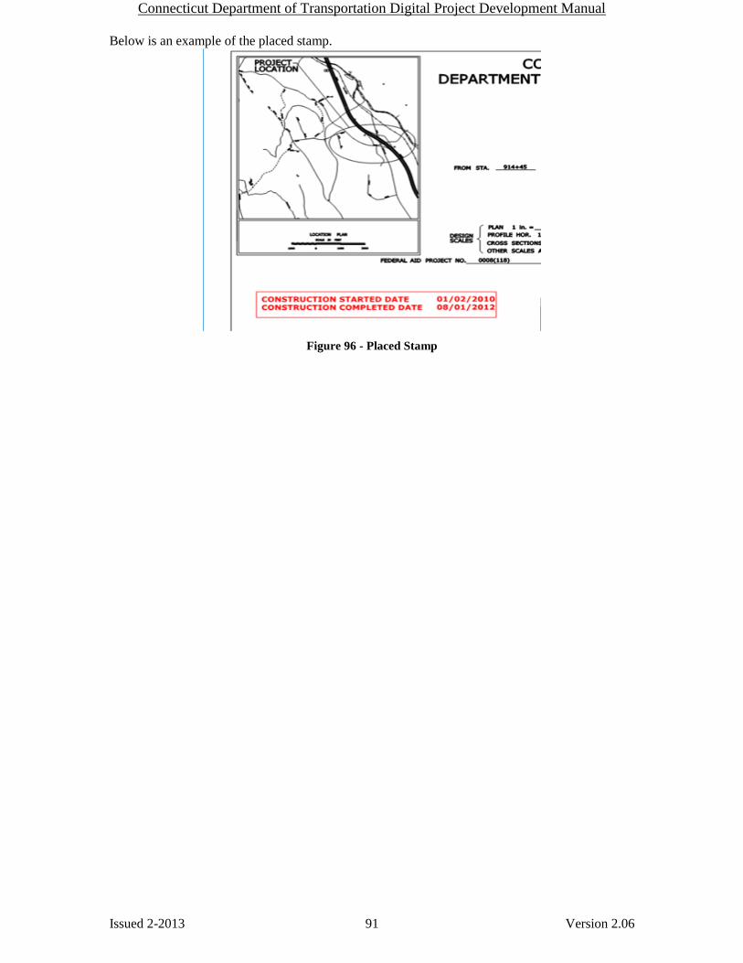
Connecticut Department of Transportation Digital Project Development Manual
Issued 2-2013 91 Version 2.06
Below is an example of the placed stamp.
Figure 96 - Placed Stamp
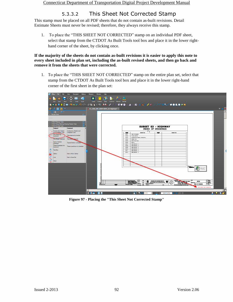
Connecticut Department of Transportation Digital Project Development Manual
Issued 2-2013 92 Version 2.06
5.3.3.2 This Sheet Not Corrected Stamp This stamp must be placed on all PDF sheets that do not contain as-built revisions. Detail
Estimate Sheets must never be revised; therefore, they always receive this stamp.
1. To place the “THIS SHEET NOT CORRECTED” stamp on an individual PDF sheet,
select that stamp from the CTDOT As Built Tools tool box and place it in the lower right-
hand corner of the sheet, by clicking once.
If the majority of the sheets do not contain as-built revisions it is easier to apply this note to
every sheet included in plan set, including the as-built revised sheets, and then go back and
remove it from the sheets that were corrected.
1. To place the “THIS SHEET NOT CORRECTED” stamp on the entire plan set, select that
stamp from the CTDOT As Built Tools tool box and place it in the lower right-hand
corner of the first sheet in the plan set:
Figure 97 - Placing the "This Sheet Not Corrected Stamp"

Connecticut Department of Transportation Digital Project Development Manual
Issued 2-2013 93 Version 2.06
2. Right click on the stamp that was placed and select “Apply to All Pages”:
Figure 98 - Placing the Stamp on All Pages
This will place the “THIS SHEET NOT CORRECTED” stamp on every plan sheet
within the pdf set.
NOTE: You must go back and replace this note on the sheets that contain as-built revisions
with the appropriate stamp.

Connecticut Department of Transportation Digital Project Development Manual
Issued 2-2013 94 Version 2.06
5.3.3.3 This Sheet Corrected
This stamp must be applied to all PDF sheets that contain as-built revisions.
1. To place the “THIS SHEET CORRECTED” stamp on an individual PDF sheet, select
that stamp from the CTDOT As-Built Tools tool box and place it in the lower right-hand
corner of the sheet, by clicking once.
If the majority of the sheets contain as-built revisions it is easier to apply this note to every
sheet included in plan set, including sheets that do not contain as-built revisions, and then
go back and replace it, with the appropriate stamp, on the sheets that were not corrected.
1. To place the “THIS SHEET CORRECTED” stamp on the entire plan set, select that
stamp from the CTDOT As Built Tools tool box and place it in the lower right-hand
corner of the first sheet in the plan set:
2. NOTE: You must go back and replace this note on the sheets that do not contain as-
built revisions with the “THIS SHEET NOT CORRECTED” stamp.
5.3.4 Applying Digital As-Built Notes To place an as-built revision, simply select any of the provided tools located within the as-built
tool box shown below and apply it to the document that is being as-built.
Figure 99 - As-Built Tools

Connecticut Department of Transportation Digital Project Development Manual
Issued 2-2013 95 Version 2.06
In the following example, the Line tool was used to cross out the existing text and the Text Box
tool was used to add text:
Figure 100 - As-Built Note Example
Additional tools are available by selecting Markup:
Figure 101 - Other Markup Tools
These tools include:
A B C D E F G H I J K L M N O P Q R
List of Commenting Tools:
A. Text – commonly used tool for as-builts
B. Typewriter – Do Not Use for As-Builts – cannot edit text
C. Note - Do Not Use for As-Builts – will not print
D. Flag
E. Pen
F. Highlight
G. Eraser - Do Not Use for As-Builts – cannot edit graphics
H. Line– commonly used tool for as-builts
I. Arrow– commonly used tool for as-builts
J. Arc
K. Polyline
L. Callout– commonly used tool for as-builts
M. Dimension
N. Box
O. Circle

Connecticut Department of Transportation Digital Project Development Manual
Issued 2-2013 96 Version 2.06
P. Polygon
Q. Cloud – Do Not Use for As-Builts - this may be confused with change orders
or addendums
R. Picture – Pictures can be inserted into a document or attached. It is
reccommended that pictures be attached as not to obstruct any part of the pdf.
Do not add a note to a comment by double clicking on the comment. For example, if a line
was placed the user could double click on the line and add notes to it:
Figure 102 - Incorect Way to Add Text
If notes are added this way they do not print.
5.3.4.1 Digital As-Built Stamps and Notes Using ADOBE
The following stamp files need to be downloaded to the user’s computer and placed in this folder:
C:\Documents and Settings\User\Application Data\Adobe\Acrobat\8.0\Stamps\. This could be
either C:\ or D:\ Drive depending on your computer. With the “User” folder being the current
user’s login Username. If Acrobat version 9 is being used, replace 8.0 with 9.0 in the previous
sentence, if version 10 is used replace with 10.
Stamp Files
As-Built stamps.pdf
Construction started and completed dates.pdf
These stamps are to be placed following Section 5.3 above.
As-Built notes shall be placed on the plans in accordance with Section 5.3 using the Adobe
commenting tools in the following format:
1. Text Font shall be Cambria 16, and the color Red.
2. All line work shall be line width 2 and the color Red.

Connecticut Department of Transportation Digital Project Development Manual
Issued 2-2013 97 Version 2.06
5.4 Notifications
5.4.1 Completion of the As-Builts After the as-built information has been completed, the person responsible for the as-builts
revisions must notify AEC Applications by filling out the following form:
As-Built Completion Form
5.4.2 Notifying Department Personnel After the as-built information has been completed and the above form has been sent to AEC
Applications, the person responsible for the as-built revisions shall notify the appropriate
Department personnel (via e-mail):
Lead Designer
Chief Inspector
Central Surveys
ROW
Central Construction
Bridge Maintenance (if a structure is on the project)

Connecticut Department of Transportation Digital Project Development Manual
Issued 2-2013 98 Version 2.06
Contractor Submittals Section 6
6.1 Working Drawings for Permanent Structures This section is in development.
6.2 Shop Drawings
This section is in development:
The following link is the Contractor Submittal workflow:

Connecticut Department of Transportation Digital Project Development Manual
Issued 2-2013 99 Version 2.06
Digital Review and Commenting Section 7
This section is in development.
This section details the procedure for digital review and commenting on pdf documents, this
includes preliminary design, working drawing, shop drawing reviews, and other contractor
submittals. Also included in this section are the stamps that are applied to working drawing and
shop drawing.
7.1 Digital Review This section is in development.
7.2 Commenting Tools
7.2.1 Bluebeam The following figures show the commenting tools in Bluebeam.

Connecticut Department of Transportation Digital Project Development Manual
Issued 2-2013 100 Version 2.06
A B C D E F G H I J K L M N O P Q R
List and Settings for Commenting Tools
A. Text - All text shall be the color “Red” and the text for a general note shall be verdana
size 12. The text for the X’d out Addendum and Change Order sheets, shall be verdana
bold size 20.
B. Typewriter – The text color shall be “Red” and Verdana size 12
C. Note – Use Default Settings
D. Flag – Use Default Settings
E. Pen – Use Default Settings
F. Highlight – Use Default Settings
G. Eraser – Use Default Settings

Connecticut Department of Transportation Digital Project Development Manual
Issued 2-2013 101 Version 2.06
H. Line – Color = Red and line width = 3.00
I. Arrow – Color = Red and line width = 3.00
J. Arc – Color = Red and line width = 3.00
K. Polyline – Color = Red and line width = 3.00
L. Callout – Adjust the properties as shown below:

Connecticut Department of Transportation Digital Project Development Manual
Issued 2-2013 102 Version 2.06
M. Dimension – Adjust as shown below and click “Set as Default”
N. Box - Color = Red and line width = 3.00
O. Circle - Color = Red and line width = 3.00
P. Polygon - Color = Red and line width = 3.00
Q. Cloud - Color = Red and line width = 3.00
R. Picture – Use default settings.
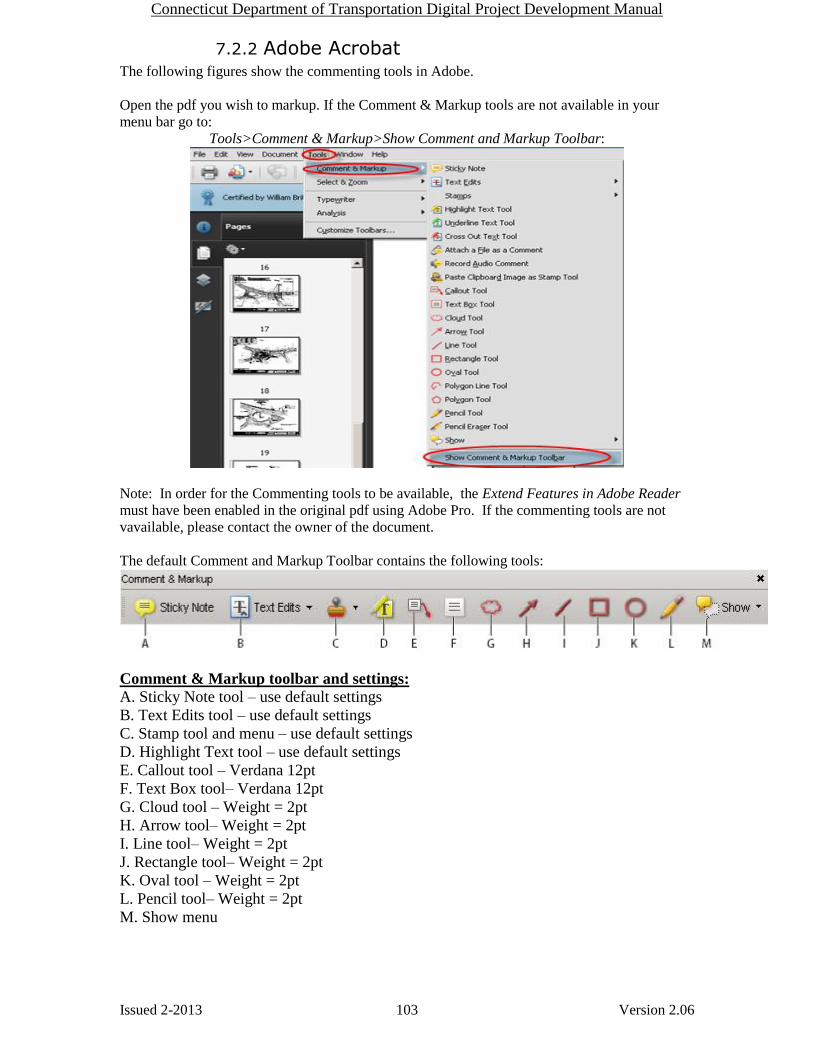
Connecticut Department of Transportation Digital Project Development Manual
Issued 2-2013 103 Version 2.06
7.2.2 Adobe Acrobat The following figures show the commenting tools in Adobe.
Open the pdf you wish to markup. If the Comment & Markup tools are not available in your
menu bar go to:
Tools>Comment & Markup>Show Comment and Markup Toolbar:
Note: In order for the Commenting tools to be available, the Extend Features in Adobe Reader
must have been enabled in the original pdf using Adobe Pro. If the commenting tools are not
vavailable, please contact the owner of the document.
The default Comment and Markup Toolbar contains the following tools:
Comment & Markup toolbar and settings:
A. Sticky Note tool – use default settings
B. Text Edits tool – use default settings
C. Stamp tool and menu – use default settings
D. Highlight Text tool – use default settings
E. Callout tool – Verdana 12pt
F. Text Box tool– Verdana 12pt
G. Cloud tool – Weight = 2pt
H. Arrow tool– Weight = 2pt
I. Line tool– Weight = 2pt
J. Rectangle tool– Weight = 2pt
K. Oval tool – Weight = 2pt
L. Pencil tool– Weight = 2pt
M. Show menu
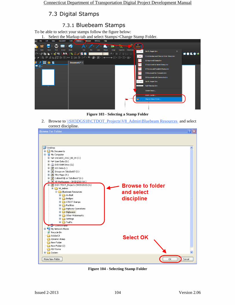
Connecticut Department of Transportation Digital Project Development Manual
Issued 2-2013 104 Version 2.06
7.3 Digital Stamps
7.3.1 Bluebeam Stamps To be able to select your stamps follow the figure below:
1. Select the Markup tab and select Stamps>Change Stamp Folder.
Figure 103 - Selecting a Stamp Folder
2. Browse to \\SH3DGS18\CTDOT_Projects\V8_Admin\Bluebeam Resources and select
correct discipline.
Figure 104 - Selecting Stamp Folder

Connecticut Department of Transportation Digital Project Development Manual
Issued 2-2013 105 Version 2.06
7.3.1.1 Placing Addendum and Change Order Stamps
When an addendum or design intitated change order are submitted, the sheets affected must get
crossed out with the apporiate note placed on them. Follow this workflow:
1. Place the Addendum and Changer Order Stamp.
2. Then using the “Text” comment tool shown in section 7.2.1 to place the notes required in
section 4.4.
3. Then select flatten markups by selecting Document>Flatten Markups. Keep the default
settings and select flatten.
7.3.2 Adobe Stamps The following stamp files need to be downloaded to the user’s computer and placed in this folder:
C:\Documents and Settings\User\Application Data\Adobe\Acrobat\8.0\Stamps\. CTDOT users
shall download this file to the same location as above but instead of the C:\ it will be in D:\. With
the “User” folder being the current user’s login Username. If Acrobat version 9 is being used,
replace 8.0 with 9.0 in the previous sentence.
Stamp Files
CTDOT_Plan_Stamp.pdf this is for the crossing out sheets due to Addendum and Change Orders.
Contractor Submittal Stamps
Shop Drawing Stamps
Working Drawing Stamps
Facilities Stamps
These stamps will need to be updated with the consultant’s information.
As-Built Stamps
As-Built stamps.pdf
Construction started and completed dates.pdf

Connecticut Department of Transportation Digital Project Development Manual
Issued 2-2013 106 Version 2.06
The figure below is an example of placing the crossed out sheet stamp:
Place stamp in correct location, then fill in the dialog box with the correct text as required. If a
mistake has been made, right click, delete and place again. After stamp is located correctly, right-
click stamp, and select properties. From Stamp Properties dialog, select “Locked”.
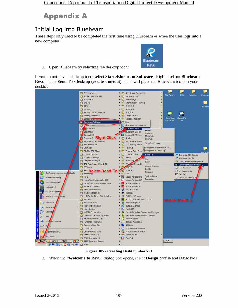
Connecticut Department of Transportation Digital Project Development Manual
Issued 2-2013 107 Version 2.06
Appendix A
Initial Log into Bluebeam These steps only need to be completed the first time using Bluebeam or when the user logs into a
new computer.
1. Open Bluebeam by selecting the desktop icon:
If you do not have a desktop icon, select Start>Bluebeam Software. Right click on Bluebeam
Revu, select Send To>Desktop (create shortcut). This will place the Bluebeam icon on your
desktop:
Figure 105 - Creating Desktop Shortcut
2. When the “Welcome to Revu” dialog box opens, select Design profile and Dark look:

Connecticut Department of Transportation Digital Project Development Manual
Issued 2-2013 108 Version 2.06
Figure 106 - Welcome to Revu
3. A dialog box may appear asking if you would like to add a ProjectWise Client Interface.
Select Yes:
Figure 107 - Bluebeam/Projectwise Link
4. Enter ProjectWise Login Name and Password. Check “Checkout on Open” and
“Checkout on Open from Hyperlinks”. Select OK:

Connecticut Department of Transportation Digital Project Development Manual
Issued 2-2013 109 Version 2.06
Figure 108 - Projectwise Login
5. Click on the settings icon in the top right hand corner and click Preferences as shown
below. If you cannot find the settings icon in the top right, go to the Edit menu and select
Preferences.
Figure 109 - Bluebeam Preferences
6. Click on File Access and make sure the box is checked as shown below: If ProjectWise is
not listed click on Add
Figure 110 - Projectwise Integration

Connecticut Department of Transportation Digital Project Development Manual
Issued 2-2013 110 Version 2.06
After you click Log in the status should read Logged In as shown below:
Figure 111 - Projectwise Integration
7. In the General section in the User area type in your name (First Initial and Last Name),
title, and your office name. An example for me would be M. Calkins TE 2 AEC
Applications. An example for a district construction user would be J. Smith TE 3 D2
Construction.
Figure 112 - General Preferences

Connecticut Department of Transportation Digital Project Development Manual
Issued 2-2013 111 Version 2.06
8. Update the markups options to match the following:
Figure 113 - Markup Preferences
9. Update the markups tab options to match the following:
Figure 114 - Markup Preferences
10. Click on the Web Tab section and make sure the box for Open PDF hyperlinks in Web
Tabs is unchecked. This will open any hyperlink that is in a PDF document using
Internet Explorer instead of Bluebeam. This is the last preference you will need to update
so you can click Ok at the bottom right now.

Connecticut Department of Transportation Digital Project Development Manual
Issued 2-2013 112 Version 2.06
Figure 115 - Webtab Preferences
Downloading the CTDOT Bluebeam Profile 1. Download this file and save it to your desktop: CTDOT Bluebeam Profile
2. Double click on the profile in the zipped folder on your desktop.
Figure 116 - Importing the Bluebeam Tools
3. In Bluebeam, on the left-hand panel, select the tool box icon and expand the CTDOT As
Built Tools:

Connecticut Department of Transportation Digital Project Development Manual
Issued 2-2013 113 Version 2.06
Figure 117 - As-Built Tools
All of the stamps and tools required for completing as-builts are now ready for use.
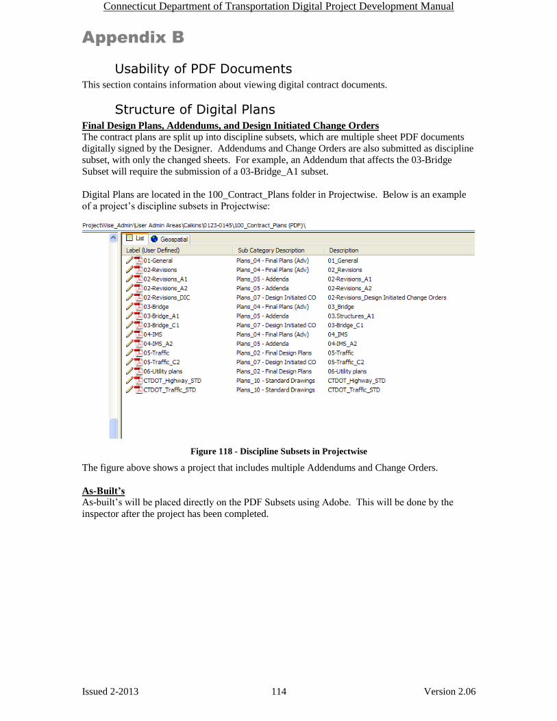
Connecticut Department of Transportation Digital Project Development Manual
Issued 2-2013 114 Version 2.06
Appendix B
Usability of PDF Documents This section contains information about viewing digital contract documents.
Structure of Digital Plans Final Design Plans, Addendums, and Design Initiated Change Orders
The contract plans are split up into discipline subsets, which are multiple sheet PDF documents
digitally signed by the Designer. Addendums and Change Orders are also submitted as discipline
subset, with only the changed sheets. For example, an Addendum that affects the 03-Bridge
Subset will require the submission of a 03-Bridge_A1 subset.
Digital Plans are located in the 100_Contract_Plans folder in Projectwise. Below is an example
of a project’s discipline subsets in Projectwise:
Figure 118 - Discipline Subsets in Projectwise
The figure above shows a project that includes multiple Addendums and Change Orders.
As-Built’s
As-built’s will be placed directly on the PDF Subsets using Adobe. This will be done by the
inspector after the project has been completed.
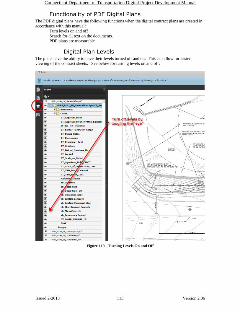
Connecticut Department of Transportation Digital Project Development Manual
Issued 2-2013 115 Version 2.06
Functionality of PDF Digital Plans The PDF digital plans have the following functions when the digital contract plans are created in
accordance with this manual:
Turn levels on and off
Search for all text on the documents.
PDF plans are measurable
Digital Plan Levels The plans have the ability to have their levels turned off and on. This can allow for easier
viewing of the contract sheets. See below for turning levels on and off:
Figure 119 - Turning Levels On and Off

Connecticut Department of Transportation Digital Project Development Manual
Issued 2-2013 116 Version 2.06
Searching Digital Plans The plans can be searched for any text located on them. This can be useful if searching for a
certain pay item.
See below for searching the PDF Plans for text.
Figure 120 - Searching for Text in PDF Plans
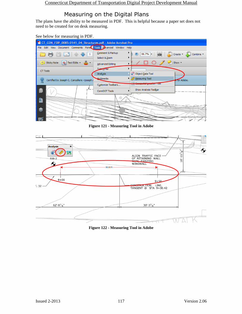
Connecticut Department of Transportation Digital Project Development Manual
Issued 2-2013 117 Version 2.06
Measuring on the Digital Plans The plans have the ability to be measured in PDF. This is helpful because a paper set does not
need to be created for on desk measuring.
See below for measuring in PDF.
Figure 121 - Measuring Tool in Adobe
Figure 122 - Measuring Tool in Adobe

Connecticut Department of Transportation Digital Project Development Manual
Issued 2-2013 118 Version 2.06
Digital Specification Package The FDP specification package will be one PDF document and located in the
110_Contract_Specifications folder. This package includes all specifications, Notice to
Contractors, Wage information, etc.
The Addendum specifications prepared in the same way as the FDP specification package and
will also be located in the 110_Contract Specifications folder.
The Design Initiated Change Order specifications will be contained in one PDF document located
in the 110_Contract Specifications folder when they are released to the Contractor.
Some useful features on the digital specification package are:
Search for any text in the document, see section 5.2.2.
Bookmarks for each section in the specification package
Figure 123 - Bookmarks in the Spec. Package


